1
1. ELECTRICAL CONNECTIONS (HFI MOTOR STARTER)
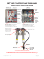
a. Wire yellow homerun control cables to car wash control panel.
(See diagram below for wiring schematic)
• Manifold position below designates which port is associated to what color wire.
• Example: if you want Presoak 1 to be on manifold port 2, connect the green wire to your
controller relay for Presoak 1.
******************(HFI supplied motor starter)******************
Make sure all BLUE wires are separately capped with wire nuts so that they do not touch any other
electrical conductive objects (One Wire Per Nut!).
(Left to right on water manifold, top to bottom
Ground: Green/yellow
on air valves refer to diagram on page 2)
5
5
2
1
Neutral / Common: Red
3
Control Voltage Constant Hot / + Brown
1
Do Not Use - Blue (Cap With Wire Nut)
2
3
1
4
5
2
3
1
5
4
3
4
Hydra-Cannon Port 1: White
Hydra-Cannon Port 2: Green
Hydra-Cannon Port 3: Yellow
5
2
3
1
4
2
3
1
5
3
4
6
4
Hydra-Cannon Port 5: Pink
5
4
2
Hydra-Cannon Port 4: Grey
2
1
To Motor Starter Box
b. Remove the cap from port 6 then, connect the grey M12 cables hanging out of the motor starter box
to the NEUTRAL/COMMON port 6 of the yellow M12 junction boxes.
i. If you have more panels than gray wires from the motor starter box, connect the lose gray
wires sent in the shipment into the same jumpers as the pre-wired gray cables. (This step
must be completed for unit to function.)
c. Connect Powerfast Cordset on motor(s) to motor starter box.
d. In the lower left of the enclosure, wire each leg of the incoming power to the
terminals labeled
2T1, 4T2, and 6T3.
•
Make sure to follow all applicable electrical codes.
2. ELECTRICAL CONNECTIONS (ONLY FOR SYSTEMS RUNNING
WITH NON HFI MOTOR STARTER)
a. Connect yellow homerun control cables to car wash control panel.
(See diagram to the right for wiring schematic)
• Manifold position below designates which port is associated to what color wire.
• Example: if you want Presoak 1 to be on manifold port 2, connect the green wire to your
controller relay for Presoak 1.
(Left to right on water manifold, top to bottom on air valves refer to diagram on page 2)
Do Not Use - Brown (Cap With Wire Nut)
Do Not Use - Red (Cap With Wire Nut)
2
1
5
5
Neutral / Common: Blue
3
i. See diagram
on pump for
wiring schematic
or pump manual.
Ground: Green/yellow
1
b. Wire each leg of
power from your
starter to each
pump.
2
3
1
4
5
2
3
1
4
5
3
4
Hydra-Cannon Port 1: White
Hydra-Cannon Port 2: Green
5
2
3
1
5
2
3
4
cap
1
5
3
4
6
4
4
Hydra-Cannon Port 4: Grey
2
1
2
Hydra-Cannon Port 3: Yellow
Hydra-Cannon Port 5: Pink
© Hydra-Flex, Inc. 2015
Page | 7