1
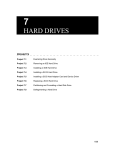
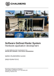
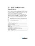
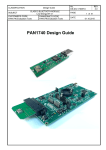
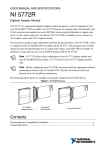
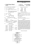
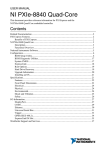
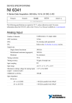
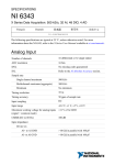
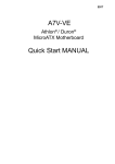
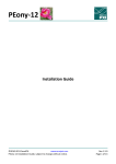
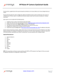
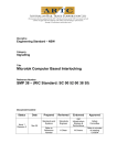
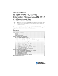
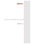
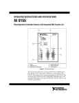
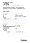
GETTING STARTED GUIDE
NI-7935R
Controller for FlexRIO™
This document describes how to begin using the NI-7935R.
Figure 1. NI-7935R
Related Information
For information about the device specifications, refer to the NI-7935R Specifications at
ni.com/manuals.
Contents
FlexRIO Documentation........................................................................................................... 2
Safety Guidelines...................................................................................................................... 4
Electromagnetic Compatibility Guidelines............................................................................... 4
Verifying the System Requirements..........................................................................................4
What You Need to Get Started..................................................................................................5
Unpacking the Kit..................................................................................................................... 5
Preparing the Environment....................................................................................................... 6
Wiring Power to the NI-7935R................................................................................................. 6
Powering on the NI-7935R....................................................................................................... 7
STATUS LED....................................................................................................................7
Connecting the NI-7935R to the Host Computer......................................................................8
Installing the FlexRIO Adapter Module................................................................................... 8
Configuring the System in Measurement & Automation Explorer (MAX)............................. 9
Setting a System Password............................................................................................. 10
Installing Software on the NI-7935R...................................................................................... 10
Adding the NI-7935R to a LabVIEW Project.........................................................................11
Adding a FlexRIO Adapter Module to the Target...........................................................11
Programming Options............................................................................................................. 11
Programming with LabVIEW......................................................................................... 12
Text-based Programming................................................................................................ 12
Removing the Adapter Module...............................................................................................12
Troubleshooting the NI-7935R............................................................................................... 12
Why Can't the NI-7935R Communicate with the Network?.......................................... 12
Why Doesn't the Device Appear in MAX?.....................................................................13
Appendix: Front Panel............................................................................................................ 13
NI-7935R Front Panel..................................................................................................... 13
Worldwide Support and Services............................................................................................ 16
Where to Go Next................................................................................................................... 16
FlexRIO Documentation
Table 1. FlexRIO Documentation Locations and Descriptions
Document
Location
Description
Getting started guide Available from the Start menu
for your controller for and at ni.com/manuals.
FlexRIO
Contains installation instructions
for your FlexRIO system.
Specifications
document for your
controller for
FlexRIO
Available from the Start menu
and at ni.com/manuals.
Contains specifications for your
controller for FlexRIO.
Getting started guide
for your adapter
module
Available from the Start menu
and at ni.com/manuals.
Contains signal information,
examples, and CLIP details for
your adapter module.
Specifications
document for your
adapter module
Available from the Start menu
and at ni.com/manuals.
Contains specifications for your
adapter module.
LabVIEW FPGA
Module Help
Embedded in LabVIEW Help
and at ni.com/manuals.
Contains information about the
basic functionality of the
LabVIEW FPGA Module.
2
|
ni.com |
NI-7935R Getting Started Guide
Table 1. FlexRIO Documentation Locations and Descriptions (Continued)
Document
Location
Description
Real-Time Module
Help
Embedded in LabVIEW Help
and at ni.com/manuals.
Contains information about realtime programming concepts, stepby-step instructions for using
LabVIEW with the Real-Time
Module, reference information
about Real-Time Module VIs and
functions, and information about
LabVIEW features on real-time
operating systems.
FlexRIO Help
Available from the Start menu
and at ni.com/manuals.
Contains information about the
FPGA module front panel
connectors and I/O, controller for
FlexRIO front panel connectors
and I/O, programming
instructions, and adapter module
component-level IP (CLIP).
FlexRIO Adapter
Available from the Start menu at
Module Development Start»All Programs»National
Kit User Manual
Instruments»NI FlexRIO»NI
FlexRIO Adapter Module
Development Kit»
Documentation.
Contains information about how
to create custom adapter modules
for use with FlexRIO FPGA
modules.
LabVIEW Examples
Available in NI Example Finder. Contains examples of how to run
In LabVIEW, click Help»Find FPGA VIs and Host VIs on your
Examples»Hardware Input
device.
and Output»FlexRIO.
IPNet
Located at ni.com/ipnet.
Contains LabVIEW FPGA
functions and intellectual property
to share.
FlexRIO product
page
Located at ni.com/flexrio.
Contains product information and
data sheets for FlexRIO devices.
Related Information
Programming with LabVIEW on page 12
NI-7935R Getting Started Guide |
© National Instruments
|
3
Safety Guidelines
Caution You can impair the protection provided by the NI-7935R if you use it in a
manner not described in this document.
Electromagnetic Compatibility Guidelines
This product was tested and complies with the regulatory requirements and limits for
electromagnetic compatibility (EMC) stated in the product specifications. These requirements
and limits provide reasonable protection against harmful interference when the product is
operated in the intended operational electromagnetic environment.
This product is intended for use in industrial locations. However, harmful interference may
occur in some installations, when the product is connected to a peripheral device or test object,
or if the product is used in residential or commercial areas. To minimize interference with
radio and television reception and prevent unacceptable performance degradation, install and
use this product in strict accordance with the instructions in the product documentation.
Furthermore, any changes or modifications to the product not expressly approved by National
Instruments could void your authority to operate it under your local regulatory rules.
Caution To ensure the specified EMC performance, operate this product only with
shielded cables and accessories. The DC power input cables and optical SFP+ cables
may be unshielded.
Caution To ensure the specified EMC performance, you must use an isolated cable
with the SFP+ ports.
Caution To ensure the specified EMC performance, the length of any cable
connected to the TRIG ports and REF CLK ports must be no longer than 3 m (10 ft).
The length of copper cables connected to the SFP+ ports must be no longer than 3 m
(10 ft). The length of cables connected to the USB device ports or host ports must be
no longer than 30 m (100 ft). The lengths of Ethernet cables and optical SFP+ cables
are not limited.
Caution The USB device port is intended only for use in device configuration,
application deployment, debug, and maintenance.
Verifying the System Requirements
To use the NI-7935R, your system must meet certain requirements. For more information
about minimum system requirements, recommended system, and supported application
development environments (ADEs), refer to the readme, which is available on the software
media or online at ni.com/updates.
4
|
ni.com |
NI-7935R Getting Started Guide
What You Need to Get Started
•
The NI-7935R shipping kit, which includes the following components:
–
The NI-7935R device
–
FlexRIO Support DVD
Note FlexRIO Support 15.1 is the earliest supported driver for the
NI-7935R.
–
–
NI-7935R Getting Started Guide (this document)
Power screw terminal connector plug
–
A to Mini-B device port USB cable
A host computer running Windows, with NI software installed in the following order:
•
–
–
–
–
Note Visit ni.com/info and enter the Info Code rdsoftwareversion to
determine which software versions you need to use the NI-7935R and
supported FlexRIO adapter modules.
LabVIEW
LabVIEW Real-Time
LabVIEW FPGA
FlexRIO Support1
•
A DC power supply as described in the NI-7935R Specifications
•
•
•
•
•
A FlexRIO adapter module or custom adapter module (optional)
A number 2 Phillips screwdriver
A number 1 Phillips screwdriver
A small flat-blade screwdriver
Straight through shielded Ethernet cable (if connecting to a network) or crossover
shielded Ethernet cable (if connecting directly to a PC)
Unpacking the Kit
Caution To prevent electrostatic discharge (ESD) from damaging the device,
ground yourself using a grounding strap or by holding a grounded object, such as
your computer chassis.
Touch the antistatic package to a metal part of the computer chassis.
1.
2.
Remove the device from the package and inspect the device for loose components or any
other sign of damage.
Caution Never touch the exposed pins of connectors.
1
LabVIEW 2015, FlexRIO Support 2015, LabVIEW Real-Time 2015, and LabVIEW FPGA 2015
are the earliest versions of software that support the NI-7935R.
NI-7935R Getting Started Guide |
© National Instruments
|
5
Note Do not install a device if it appears damaged in any way.
3.
Unpack any other items and documentation from the kit.
Store the device in the antistatic package when the device is not in use.
Preparing the Environment
Ensure that the environment you are using the NI-7935R in meets the following specifications.
Operating temperature (IEC 60068-2-1,
IEC 60068-2-2)
0 °C to 55 °C
Operating humidity (IEC 60068-2-56)
10% to 90% RH, noncondensing
Pollution Degree
2
Maximum altitude
2,000 m at 25 °C ambient temperature
Indoor use only.
Note Refer to the NI-7935R Specifications at ni.com/manuals for complete
specifications.
Caution Clean the hardware with a soft, nonmetallic brush. Make sure that the
hardware is completely dry and free from contaminants before returning it to
service.
Wiring Power to the NI-7935R
The NI-7935R requires a 9 V to 30 V external power supply that meets the specifications in
the NI-7935R Specifications. The NI-7935R filters and regulates the supplied power and
provides power for the I/O modules.
Note You can latch the power plug to the NI-7935R using two screws tightened to
0.20 to 0.25 N · m (1.8 to 2.2 lb · in.) of torque.
The maximum wire gage accepted by the power connector plug is 16 AWG. You must use a
stripped wire length of 10 mm (.394 in).
When the POWER LED on the front panel is lit green, the device is powered.
The NI-7935R has reverse-voltage protection.
Complete the following steps to connect a power supply to the NI-7935R.
1. Ensure the power source is turned off.
2.
6
Connect a positive wire to the positive terminal of the power connector plug, and connect
a negative wire to the negative terminal of the power connector plug.
|
ni.com
|
NI-7935R Getting Started Guide
1
2
3
1. Positive terminal
2. Negative terminal
3. No connect
3.
Install the power connector on the front panel of the NI-7935R.
4.
Turn on the external power source(s).
Powering on the NI-7935R
When you apply power for the first time to the NI-7935R, the controller boots into safe mode.
The POWER LED illuminates, the STATUS LED illuminates briefly, and then the STATUS
LED blinks twice every few seconds.
After you install software on the controller, subsequent reboots will boot the controller into the
NI Linux Real-Time operating system.
You can optionally configure the NI-7935R to launch an embedded stand-alone LabVIEW
Real-Time application each time you boot the controller.
STATUS LED
The STATUS LED is off during normal operation. The NI-7935R indicates specific error
conditions by flashing the STATUS LED a certain number of times every few seconds, as
shown in the following table.
LED State
2 flashes every few
seconds
Indication
There is no software installed, which is the out-of-box state, or the
controller has detected an error in its software.
An error can occur when an attempt to upgrade the software is
interrupted. Refer to the MAX Help for information about reinstalling
software on the controller.
3 flashes every few
seconds
The controller is in safe mode. Refer to the MAX Help for
information about safe mode.
NI-7935R Getting Started Guide |
© National Instruments
|
7
LED State
Indication
4 flashes every few
seconds
The software has crashed twice without rebooting or cycling power
between crashes. This usually occurs when the controller runs out of
memory. Review your Real-Time VI and check the memory usage.
Modify the VI as necessary to solve the memory usage issue.
Continuously
flashing
The controller has not booted into NI Linux Real-Time. The
controller either booted into an unsupported operating system, was
interrupted during the boot process, or detected an unrecoverable
software error.
Solid
The controller is booting up.
Continuously
flashing
This indicates a hardware error. An internal power supply has failed.
Check front-panel I/O and adapter module connections for shorts.
Remove any shorts and power cycle the controller. If the problem
persists, contact National Instruments.
Off
Normal operation.
Connecting the NI-7935R to the Host Computer
Complete the following steps to connect the NI-7935R to the host computer using the USB
device port.
1. Power on the host computer.
2.
Connect the NI-7935R to the host computer using the USB A-to-B cable.
Note Alternatively, you can use the RJ-45 Ethernet port to connect the
NI-7935R to the host computer.
The device driver software automatically detects the NI-7935R. If the device driver
software does not detect the NI-7935R, verify that you installed the appropriate NI
software in the correct order on the host computer.
Tip You can also use the Ethernet port to connect directly to the host computer or
network. Refer to the user manual on ni.com/manuals for more information about
Ethernet connections.
Related Information
Troubleshooting the NI-7935R on page 12
Installing the FlexRIO Adapter Module
Skip this section if you are not using a FlexRIO adapter module.
8
|
ni.com |
NI-7935R Getting Started Guide
1.
Gently insert the guide pins and the high-density card edge of the FlexRIO adapter
module into the corresponding connectors of the NI-7935R.
The connection may be tight, but do not force the adapter module into place.
2.
Tighten the captive screws on the FlexRIO adapter module to secure it to the NI-7935R.
The following figure shows the NI-7935R with the FlexRIO adapter module connected.
Figure 2. NI-7935R with FlexRIO Adapter Module
Refer to the getting started guide for your adapter module for more information about your
adapter module, including programming information.
Configuring the System in Measurement &
Automation Explorer (MAX)
After connecting the NI-7935R to the host computer, complete the following steps to
configure the system for the first time in MAX.
1. Launch MAX on the host computer.
2.
Expand Remote Systems in the MAX configuration tree and select the system. MAX
lists the system as the model name followed by the serial number, such as
NI-7935R-030521C9.
Related Information
Why Doesn't the Device Appear in MAX? on page 13
NI-7935R Getting Started Guide |
© National Instruments
|
9
Setting a System Password
Complete the following steps to set a system password.
Note Setting a system password is optional.
Note The default username for the NI-7935R is admin. There is no default
password for the NI-7935R, so you must leave the password field blank when
logging in until you set a system password.
Right-click your system and select Web Configuration.
1.
The NI Web-based Configuration and Monitoring utility opens in your default browser
and is where you set the password. If you have not installed Microsoft Silverlight,
NI Web-based Configuration & Monitoring prompts you to do so.
2.
Enter a unique name for your system in the Hostname field.
3.
Click the Security Configuration icon.
4.
Click Login.
5.
In the Login dialog box, enter the username admin and leave the password field blank.
6.
Click OK.
7.
Click Change Password.
8.
Enter and re-enter a new password.
9.
Click OK.
10. Click Save.
11. Click OK to confirm you are changing the password.
Caution NI cannot recover lost system passwords. If you forget the password,
you must contact NI and reformat the controller.
Installing Software on the NI-7935R
1.
Open Measurement & Automation Explorer (MAX).
2.
Expand the system under Remote Systems by clicking the arrow beside it.
3.
Select Software.
4.
Click Add/Remove Software at the top of the Software tab to launch the LabVIEW
Real-Time Software Wizard.
Note A login window appears if you set a system password.
5.
Select a recommended software set to install.
6.
Click Next.
10
|
ni.com |
NI-7935R Getting Started Guide
7.
The recommended software set is preselected from the list of software add-ons. Check
any additional software add-ons you want. The System State Publisher, for example,
makes monitoring system performance simple.
Note You can use the LabVIEW Real-Time Software Wizard to install more
software add-ons later. The FlexRIO 15.0 Recommended Software Set is
enough to get started.
8.
Click Next.
9.
Review the summary of software to install. Click Next to begin the update.
10. Wait for the installation to finish, and then click Finish.
Adding the NI-7935R to a LabVIEW Project
1.
Launch LabVIEW. The LabVIEW Getting Started window appears.
2.
Click Create Project or open an existing project.
3.
Right-click the project root in the Project Explorer window and select New»Targets
and Devices from the shortcut menu to display the Add Targets and Devices dialog box.
a) If the hardware is connected to the host, select Existing target or device. Select the
NI-7935R under Real-Time FlexRIO and click OK.
b) If the hardware is not connected to the host, select New target or device. Select the
NI-7935R under Real-Time FlexRIO and click OK.
4.
Right-click the target and select New»FPGA Target.
The FPGA target appears in the project under the Real-Time target.
Adding a FlexRIO Adapter Module to the Target
Skip this section if you are not using an adapter module.
1. Expand the FPGA target by clicking the + button, then right-click IO Module and select
Properties.
2.
Select the General category and check the Enable IO Module box.
3.
Select your I/O module from the IO Modules list, and select the CLIP you want to use
from the Component Level IP box.
4.
Click OK.
Programming Options
Refer to the following table for information about how to program the NI-7935R.
Component
Programming Option(s)
Real-Time controller LabVIEW Real-Time or C/C++ Development Tools for NI Linux
Real-Time, Eclipse Edition.
FPGA
LabVIEW FPGA
NI-7935R Getting Started Guide
|
© National Instruments
|
11
Programming with LabVIEW
The Controller for FlexRIO examples provide a starting point for programming with
LabVIEW. To access these examples, open LabVIEW and select Help»Find Examples»
Hardware Input and Output»Controller for FlexRIO.
For more detailed instructions about programming the NI-7935R with LabVIEW, refer to the
NI-7931R/7932R/7935R User Manual.
Related Information
FlexRIO Documentation on page 2
Text-based Programming
You can target the NI-7935R Linux Real-Time operating system from text-based development
environments such as C and C++.
Related Information
For more information about text-based programming, refer to the Getting Started with C/C++
Development Tools for NI Linux Real-Time, Eclipse Edition tutorial.
Removing the Adapter Module
Complete the following steps to remove an adapter module from the NI-7935R.
1. Disconnect all cables to the adapter module.
2. Power off the NI-7935R.2
3. Unscrew the adapter module.
4. Remove the adapter module.
Troubleshooting the NI-7935R
Related Information
Connecting the NI-7935R to the Host Computer on page 8
Why Can't the NI-7935R Communicate with the
Network?
1.
Connect cables from your device to the host computer.
a) If you are using the USB port, use a USB cable to connect the NI-7935R USB
device port to a host computer.
The USB driver creates a virtual network interface and assigns an IP address to the
NI-7935R in the format of 172.22.11.x.
2
12
|
If you cannot power down the NI-7935R, use the System Configuration application programming
interface (API) to disable power to the adapter module.
ni.com |
NI-7935R Getting Started Guide
b)
If you are using the ethernet port, use an ethernet to connect the ethernet port to the
host computer.
2.
In MAX, expand your system under Remote Systems.
3.
Select the Network Settings tab to configure the IP and other network settings.
4.
(Optional) Use the RJ-45 Ethernet port 1 to reconnect the NI-7935R to the host computer.
The NI-7935R attempts to initiate a DHCP network connection at powerup.
If the NI-7935R cannot contain an IP address, it connects to the network with a link-local
IP address with the form 169.254.x.x. The host computer communicates with the
NI-7935R over a standard Ethernet connection.
Why Doesn't the Device Appear in MAX?
If you cannot find the NI-7935R in MAX, complete the following steps.
•
Ensure you have the correct version of FlexRIO Support installed on the host computer.
•
Check the USB cable connections at the NI-7935R and host computer. Check the
Ethernet cable connections at the host computer and router.
•
If you have network firewalls or other security software enabled, try temporarily turning
them off. You may also need to add an exception for MAX. In Windows 7, select Start»
Control Panel»System and Security»Windows Firewall»Allow a program through
Windows Firewall. Click Allow another program, select Measurement &
Automation, click Add, then click OK.
•
•
•
•
Ensure that UDP port 44525 is open to communication on the host computer. If you are
using an intelligent switch on the network, ensure that it is not disabling UDP port 44525.
Hold down the RESET button for 5 seconds to reboot the target into safe mode. This
prevents a real-time app from running. Sometimes a malfunctioning real-time app
prevents network communication.
Check the Device Manager to ensure the National Instruments USBLAN adapter is
recognized. In Windows 7, select Start»Control Panel»Device Manager»Network
adapters»National Instruments»USBLAN adapter. If the USBLAN adapter is not
recognized, you must reinstall FlexRIO Support.
Ensure that the Ethernet cable is connected correctly.
Related Information
Configuring the System in Measurement & Automation Explorer (MAX) on page 9
Appendix: Front Panel
NI-7935R Front Panel
The following figure shows the NI-7935R front panel connectors, buttons, and LEDs.
NI-7935R Getting Started Guide
|
© National Instruments
|
13
Figure 3. NI-7935R
1
2
7
10
9
11
1.
2.
3.
4.
5.
6.
3
TRIG
REF CLK
Storage (µSD card)
USB device port
USB host
1 Gigabit Ethernet
4
5
6
8
7. LED indicators
8. Reset
9. DC power source
10. FlexRIO adapter module connector
11. Port 0/Port 1 (SFP+ connectors)
Related Information
For more information about the NI-7935R front panel connectors, buttons, and LEDs, refer to
the FlexRIO Help.
LED Indicators
The following figure shows the NI-7935R LEDs in more detail.
Figure 4. NI-7935R LEDs
Power
LED
FPGA User
LED
14
|
ni.com |
NI-7935R Getting Started Guide
Status
LED
RT User
LED
NI-7935R Module Signals
The following figure shows the available signals on the NI-7935R.
GND
GPIO_CC_38_n
GPIO_CC_38
GND
GPIO_39_n
GPIO_39
GND
GPIO_40_n
GPIO_40
GND
GPIO_41_n
GPIO_41
GND
GPIO_42_n
GPIO_42
GND
GPIO_43_n
GPIO_43
GND
GPIO_44_n
GPIO_44
GND
GPIO_45_n
GPIO_45
GND
GPIO_46_n
GPIO_46
GND
GPIO_47_n
GPIO_47
GND
GPIO_48_n
GPIO_48
GND
GPIO_49_n
GPIO_49
GND
GPIO_CC_50_n
GPIO_CC_50
GND
GPIO_51_n
GPIO_51
GND
GPIO_52_n
GPIO_52
GND
GPIO_53_n
GPIO_53
GND
GPIO_54_n
GPIO_54
GND
GPIO_55_n
GPIO_55
GND
GPIO_56_n
GPIO_56
GND
GPIO_57_n
GPIO_57
GND
G21
S40
S39
G20
S38
S37
G19
S36
S35
G18
S34
S33
G17
S32
S31
G16
S30
S29
G15
S28
S27
G14
S26
S25
G13
S24
S23
G12
S22
S21
G11
S20
S19
G10
S18
S17
G9
S16
S15
G8
S14
S13
G7
S12
S11
G6
S10
S9
G5
S8
S7
G4
S6
S5
G3
S4
S3
G2
S2
S1
G1
NI-7935R Getting Started Guide
|
PCB
Primary Side
G21
S114
S113
G20
S112
S111
G19
S110
S109
G18
S108
S107
G17
S106
S105
G16
S104
S103
G15
S102
S101
G14
S100
S99
G13
S98
S97
G12
S96
S95
G11
S94
S93
G10
S92
S91
G9
S90
S89
G8
S88
S87
G7
S86
S85
G6
S84
S83
G5
S82
S81
G4
S80
S79
G3
S78
S77
G2
S76
S75
G1
GND
GPIO_CC_14_n
GPIO_CC_14
GND
GPIO_15_n
GPIO_15
GND
GPIO_16_n
GPIO_16
GND
GPIO_17_n
GPIO_17
GND
GPIO_18_n
GPIO_18
GND
GPIO_19_n
GPIO_19
GND
GPIO_20_n
GPIO_20
GND
GPIO_21_n
GPIO_21
GND
GPIO_22_n
GPIO_22
GND
GPIO_23_n
GPIO_23
GND
GPIO_58_n
GPIO_58
GND
GPIO_59_n
GPIO_59
GND
GPIO_CC_60_n
GPIO_CC_60
GND
GPIO_61_n
GPIO_61
GND
GPIO_62_n
GPIO_62
GND
GPIO_63_n
GPIO_63
GND
GPIO_64_n
GPIO_64
GND
GPIO_65_n
GPIO_65
GND
GPIO_66_n
GPIO_66
GND
GPIO_67_n
GPIO_67
GND
© National Instruments
Bank 1
+3.3V
SCL
TB_Present
+12V
Vcco
RSVD
GND
IOModSyncClk_n
IOModSyncClk
GND
GPIO_0_n
GPIO_0
GND
GPIO_1_n
GPIO_1
GND
GPIO_CC_2_n
GPIO_CC_2
GND
GPIO_3_n
GPIO_3
GND
GPIO_4_n
GPIO_4
GND
GPIO_5_n
GPIO_5
GND
GPIO_6_n
GPIO_6
GND
GPIO_7_n
GPIO_7
GND
GPIO_8_n
GPIO_8
GND
GPIO_9_n
GPIO_9
GND
GPIO_10_n
GPIO_10
GND
GPIO_11_n
GPIO_11
GND
GPIO_12_n
GPIO_12
GND
GPIO_13_n
GPIO_13
GND
Bank 0
P1
S148
S147
P2
S146
S145
G37
S144
S143
G36
S142
S141
G35
S140
S139
G34
S138
S137
G33
S136
S135
G32
S134
S133
G31
S132
S131
G30
S130
S129
G29
S128
S127
G28
S126
S125
G27
S124
S123
G26
S122
S121
G25
S120
S119
G24
S118
S117
G23
S116
S115
G22
Bank 2
P1
S74
S73
P2
S72
S71
G37
TDC_Assert_CLK_n S70
TDC_Assert_CLK
S69
GND
G36
GPIO_24_n
S68
GPIO_24
S67
GND
G35
GPIO_25_n
S66
GPIO_25
S65
GND
G34
GPIO_CC_26_n S64
GPIO_CC_26
S63
GND
G33
GPIO_27_n
S62
GPIO_27
S61
GND
G32
GPIO_28_n
S60
GPIO_28
S59
GND
G31
GPIO_29_n
S58
GPIO_29
S57
GND
G30
GPIO_30_n
S56
GPIO_30
S55
GND
G29
GPIO_31_n
S54
GPIO_31
S53
GND
G28
GPIO_32_n
S52
GPIO_32
S51
GND
G27
GPIO_33_n
S50
GPIO_33
S49
GND
G26
GPIO_34_n
S48
GPIO_34
S47
GND
G25
GPIO_35_n
S46
GPIO_35
S45
GND
G24
GPIO_36_n
S44
GPIO_36
S43
GND
G23
GPIO_37_n
S42
GPIO_37
S41
GND
G22
Bank 1
Bank 0
+3.3V
SDA
TB_Power_Good
+12V
Vcco
Veeprom
GND
PCB
Secondary Side
PCB
Primary Side
Bank 2
PCB
Secondary Side
|
15
Worldwide Support and Services
The National Instruments website is your complete resource for technical support. At ni.com/
support, you have access to everything from troubleshooting and application development
self-help resources to email and phone assistance from NI Application Engineers.
Visit ni.com/services for NI Factory Installation Services, repairs, extended warranty, and
other services.
Visit ni.com/register to register your National Instruments product. Product registration
facilitates technical support and ensures that you receive important information updates from
NI.
A Declaration of Conformity (DoC) is our claim of compliance with the Council of the
European Communities using the manufacturer’s declaration of conformity. This system
affords the user protection for electromagnetic compatibility (EMC) and product safety. You
can obtain the DoC for your product by visiting ni.com/certification. If your product supports
calibration, you can obtain the calibration certificate for your product at ni.com/calibration.
National Instruments corporate headquarters is located at 11500 North Mopac Expressway,
Austin, Texas, 78759-3504. National Instruments also has offices located around the world.
For telephone support in the United States, create your service request at ni.com/support or
dial 1 866 ASK MYNI (275 6964). For telephone support outside the United States, visit the
Worldwide Offices section of ni.com/niglobal to access the branch office websites, which
provide up-to-date contact information, support phone numbers, email addresses, and current
events.
Where to Go Next
Refer to the following figure for information about other product tasks and associated
resources for those tasks.
16
|
ni.com
|
NI-7935R Getting Started Guide
EXPLORE
LEARN
CREATE
the application development
environment (ADE)
appropriate for your application.
about the capabilities of
your hardware with device
specifications.
custom applications within an
application programming
interface (API).
Getting Started with
LabVIEW
NI -7935R
Specifications
LabVIEW FPGA
Module Help
FlexRIO Help
FlexRIO Support
FlexRIO Examples
NI-7931/7932/7935
User Manual
LabVIEW Real-Time
Module Help
FlexRIO Help
DISCOVER
more about your products through ni.com.
Support
ni.com/support
FlexRIO
ni.com/flexrio
Located online at ni.com/manuals
Services
ni.com/services
Updates
ni.com/updates
Located using the NI Example Finder
NI-7935R Getting Started Guide
|
© National Instruments
|
17
Refer to the NI Trademarks and Logo Guidelines at ni.com/trademarks for information on NI trademarks. Other product and
company names mentioned herein are trademarks or trade names of their respective companies. For patents covering NI
products/technology, refer to the appropriate location: Help»Patents in your software, the patents.txt file on your media, or the
National Instruments Patent Notice at ni.com/patents. You can find information about end-user license agreements (EULAs)
and third-party legal notices in the readme file for your NI product. Refer to the Export Compliance Information at ni.com/
legal/export-compliance for the NI global trade compliance policy and how to obtain relevant HTS codes, ECCNs, and other
import/export data. NI MAKES NO EXPRESS OR IMPLIED WARRANTIES AS TO THE ACCURACY OF THE INFORMATION
CONTAINED HEREIN AND SHALL NOT BE LIABLE FOR ANY ERRORS. U.S. Government Customers: The data contained in
this manual was developed at private expense and is subject to the applicable limited rights and restricted data rights as set forth
in FAR 52.227-14, DFAR 252.227-7014, and DFAR 252.227-7015.
© 2015 National Instruments. All rights reserved.
374951B-01
Sep15