1
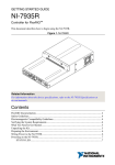
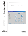
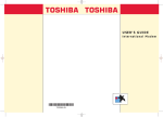
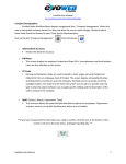
7 HARD DRIVES PROJECTS Project 7.1 Examining Drive Geometry Project 7.2 Removing an IDE Hard Drive Project 7.3 Installing an IDE Hard Drive Project 7.4 Installing a SATA Hard Drive Project 7.5 Installing a SCSI Host Adapter Card and Device Driver Project 7.6 Replacing a SCSI Hard Drive Project 7.7 Partitioning and Formatting a Hard Disk Drive Project 7.8 Defragmenting a Hard Drive 111 112 PC Hardware Essentials Project Manual Project 7.1 Examining Drive Geometry Overview To understand how disks store data, you need to understand disk geometry, which refers to the electronic organization of the disk drive. The components of disk geometry include the physical number of read/write heads (usually one for each side of the platter), and the number of cylinders, tracks, and sectors of the disk. You can use this information to determine the storage capacity of a hard drive. In this project, you will examine the drive geometry (cylinders, heads, and sectors) of a hard drive. Older drives list the cylinders, heads, and sectors (or the sectors per track—SPT). (Note that because the number of tracks per surface is the same as the number of cylinders on the drive, manufacturers only report the number of cylinders, not tracks.) Outcomes After completing this project, you will know how to: identify the drive geometry of a hard drive use drive geometry information to calculate the available data storage space on the drive What you’ll need To complete this project, you will need: an older IDE hard drive that lists the cylinders, heads, and sectors, and which has already been removed from the computer a calculator Completion time 30 minutes Precautions On newer drives (generally those that can store over 8.4 GB), the drive will list the mode, such as LBA (Logical Block Addressing) and the number of hard drive sectors. For such hard drives, you cannot use the below steps to calculate storage capacity. 1. Examine the hard drive to locate a section labeled Parameters (Figure 7-1). Hard Drives s113 Figure 7-1: Locating the Parameters section on a hard drive 2. Enter the information you find: Cylinders: _________________________________________________________________ Heads: ____________________________________________________________________ Sectors: ___________________________________________________________________ 3. Calculate drive geometry using the formula: Cylinders x Heads x Sectors x 512 = Drive Capacity. __________________________________________________________________________ 4. Convert the result above into MB by dividing by 1,000,000 or into GB by dividing by 1,000,000,000. __________________________________________________________________________ 5. What is the storage capacity of the drive? __________________________________________________________________________ 114 PC Hardware Essentials Project Manual 6. What is the storage capacity of a drive with the following drive geometry: 15690 cylinders, 16 heads and 63 sectors per track. ___________________________________________________________________________ Project 7.2 Removing an IDE Hard Drive Overview IDE (Integrated Device Electronics) is an interface for connecting storage devices such as hard drives, tape drives and optical (CD/DVD) drives. IDE is a specification that was originally written in 1988. When it was accepted as an ANSI standard, it was renamed Advanced Technology Attachment (ATA). The first ATA standards used a parallel bus, and are referred to as parallel ATA or PATA. The most recent ATA standards are based on a serial bus and referred to as serial ATA (SATA). IDE has been the most popular interface for hard disk drives in mainstream systems for many years, which means that you will very likely be called upon to remove and install them. In this project, you will identify and remove an IDE hard drive. Outcomes After completing this project, you will know how to: identify an IDE hard drive remove an IDE hard drive What you’ll need To complete this project, you will need: working Windows computer with an IDE hard drive installed a technician’s toolkit with antistatic wrist strap and antistatic mat Completion time 60 minutes Precautions Be sure to take all necessary ESD precautions. Also make sure that any data on the hard drive that you will be removing has been backed up. 1. If necessary, turn on the computer, and access the CMOS setup routine (also referred to as the BIOS setup program or BIOS screen). The CMOS setup routine is available for only a short time during the book sequence. Most computer manufacturers tell you how to enter the CMOS startup screen as the computer is booting, typically by pressing a specific key or + . The initial screen typically displays a menu of combination, such as configuration categories, each of which lead to one or more additional menu screens and key. options (Figure 7-2). Select the Drive Configuration option and press the Record the information that appears. Hard Drives s115 ___________________________________________________________________________ ___________________________________________________________________________ __________________________________________________________________________ Figure 7-2: Accessing the CMOS setup routine 2. When you have finished recording the information, press the key and allow the computer to finish booting. 3. Shut down the computer and disconnect the power cable, along with any external peripheral cables. 4. Carefully remove the computer case. Note: As soon as the cover is removed, put on your antistatic wrist strap to protect the computer from ESD. 5. Prepare a sketch that shows where each expansion card goes in the motherboard expansion slots and where any cables or wires are connected to the expansion card. On this sketch, note the pin 1 edge (the edge that has a stripe) on the cables and the colors of individual wires attached to the expansion card. ___________________________________________________________________________ 116 PC Hardware Essentials Project Manual 6. If any of the expansion cards are obstructing your access to the hard drive, you will need to remove them. Disconnect the wires and cables that are connected to the expansion card, remove the mounting screw, grasp the expansion card with both hands, and pull upward while gently rocking the board from front to back (Figure 7-3). Note: As soon as the expansion card is out, place it on an antistatic mat to protect against ESD. Figure 7-3: Removing the expansion card 7. The power cable plug on the hard drive is keyed so it fits only one way, but the ribbon (data) cable can be accidentally reversed if it is not keyed. To keep this from happening, note the pin 1 position of the hard drive so you can later match it with the striped edge on the data cable when the drive is reinstalled. After you’ve done this, disconnect the data cable (ribbon cable) and power cable from the hard drive. 8. Physically remove the hard drive from the computer. Unbolt the hard drive from the drive bay and then remove the drive from the computer. 9. In another sketch, draw the hard-drive jumper block and show the current jumper settings. ___________________________________________________________________________ Note: The jumper settings should be master or single if this is the bootable drive. If the jumper settings do not match the installation, the drive will not function. Hard drive jumpers found in various locations on hard drives set the installation options. If any hard drive jumper is moved, the hard-drive configuration is changed. Sometimes it is very difficult to find documentation for jumper settings. Hard drives may be configured as master, single, slave, or cable select. The hard-drive configuration must match the drive’s usage. The cable select status permits the computer to automatically select the master or slave status, but it requires a special hard-drive cable that is identified by a notch or hole in the cable. Hard Drives s117 Project 7.3 Installing an IDE Hard Drive Overview Before installing a new IDE hard drive, you will need to plan how it will be configured. IDE drives are connected to the motherboard using an IDE ribbon cable. Motherboards typically have two connectors for IDE ribbon cables, called the primary IDE channel and the secondary IDE channel. The IDE ribbon cables themselves have a connector for attaching to the motherboard and one or two connectors for the IDE drives. If two drives are connected with the same ribbon cable, one drive must be designated as Master and one as Slave. This configuration is done typically through jumpers or switches on the drive itself. Other drive configuration options include Single, which specifies that there is only one drive on the ribbon cable, and Cable Select. You can use a Cable Select configuration when you are using a Cable Select ribbon, which automatically designates one position on the cable as master and the other as slave. In general, for best performance, it is best to have drives on their own separate ribbon cable. If you need to install a second drive on a ribbon cable, choose the newest, fastest, or most used to act as Master. In this project, you will determine the hard-drive setup information for the drive to be installed, set the hard-drive jumpers, install the hard drive, and then configure the CMOS if the drive is not automatically detected. You can install the same hard drive as you removed in the previous project or a different one. Outcomes After completing this project, you will know how to: install an IDE hard drive What you’ll need To complete this project, you will need: the computer from which you removed the hard drive in Project 7.2 a bootable floppy start-up disk an IDE hard drive compatible with the BIOS of the computer and the operating system that can be installed a ribbon cable for an IDE drive a Molex power connector that matches the plug on the drive a technician’s tool kit with antistatic wrist strap and mat the manual that came with the drive (optional but recommended) Completion time 60 minutes Precautions Be sure to take all necessary ESD precautions. 1. Research the settings for the new hard drive and record the jumper and CMOS setup information in the space provided: Jumper settings: _________________________________________ 118 PC Hardware Essentials Project Manual Cylinders: __________________________________________________________________ Heads: ____________________________________________________________________ Sectors: ____________________________________________________________________ Note: Newer hard drives have diagrams of their jumper blocks on their labels. 2. If necessary, shut down the computer. Remove the power cable from the computer and carefully open the computer case. Locate an available drive bay, and identify where the cables will connect. 3. Set the jumpers on the new hard drive so they have the same function (master, slave, or cable select) as the drive you removed from the computer. The jumper blocks may be very different. Record how you set the jumpers. ____________________________________________ 4. Insert the new hard drive into the drive bay, securing it with mounting rails or screws. 5. Attach the ribbon cable (Figure 7-4) to the hard disk drive and motherboard or the hard disk controller, with the striped edge of the ribbon cable on pin 1 of the plugs. On early hard drives and on most new hard drives, the drive that is attached to the end of the ribbon cable is the C: drive. For some systems, the drive position on the ribbon cable does not matter. Figure 7-4: Ribbon cable 6. Connect a power cable from the power supply to the drive. 7. Reassemble the computer (replace the expansion cards if you removed any and the cover). 8. Start the CMOS setup sequence and make sure the settings match those of the new drive. Usually the hard drive is automatically detected; however, if the computer BIOS does not automatically detect the drive, you must set the heads, cylinders, and sectors manually. Sometimes a hard drive is detected with the wrong settings. The wrong settings may cause the hard drive to be installed with the wrong size specified. 9. Exit the CMOS setup. The computer will reboot. 10. Boot to a startup disk in the A: drive and then type A:\>C: to attempt to access the hard drive you just installed. 11. If you see the message INVALID DRIVE SPECIFICATION, the drive needs to be formatted. Type A:\>FORMAT C: to format the new drive. 12. When the format is complete, type A:\>C: to access the hard drive. Hard Drives s119 13. If the C: prompt is displayed, the installation is a success. Project 7.4 Installing a SATA Hard Drive Overview SATA drives are a faster alternative to IDE drives. They support greater storage capacities and higher data transfer speed. SATA drives use a narrower, and longer data cable that allows for better airflow and more flexibility in mounting a hard disk inside the PC case. The SATA power cable has a new type of 15-pin power connector. The SATA data cable connects to a new 7-pin IDE header directly integrated on the motherboard or on a PCI SATA expansion card. SATA drives also operate at lower voltages than IDE drives, reducing power consumption. Another important feature is that SATA drives are hot-swappable under Windows 2000, Windows XP, Windows Vista, and Windows Server 2003. One hard drive can be removed and another plugged in without rebooting the computer. The hot-swap feature and the higher data transfer speeds suggest that SATA drives may become a competitive alternative to SCSI hard disks. Many PC motherboards in current use do not have onboard support for SATA drives. SATA support can be added to these systems through PCI SATA expansion cards from third-party vendors. Typically, these expansion cards can support two or more SATA drives. Outcomes After completing this project, you will know how to: install a SATA hard drive in a computer What you’ll need To complete this project, you will need: a Windows computer with a free drive bay and a motherboard that includes onboard SATA support (if it does not, you must first install a PCI SATA expansion card) an appropriate SATA hard drive a technician’s toolkit with antistatic wrist strap Completion time 60 minutes Precautions Be sure to take all necessary ESD precautions. You will need to ensure that drive you are installing is compatible with the motherboard. 1. Back up the data on existing hard disks in your PC. 2. Review the documentation included with your motherboard or third-party SATA expansion card. If necessary, install a PCI SATA expansion card if the motherboard does not include onboard SATA support. 3. Find an empty drive bay for the SATA drive; or rearrange the positions of existing storage devices, removing the old hard drive, if necessary. 4. Insert the SATA drive in the drive bay and secure it in place. 120 PC Hardware Essentials Project Manual 5. Attach the 4-pin side of a Molex-to-SATA power cable to a Molex cable from your power supply and attach the 15-pin side to the SATA power connector on the SATA drive (Figure 7-5). (A PC that includes direct SATA support may include a power supply with a native 15pin power cable.) Figure 7-5: SATA power cable 6. Connect the 7-pin data cable to the SATA connector on the drive and to the SATA-1 header on the motherboard or PCI expansion card. Figure 7-6: SATA data cable 7. Reconnect any drives, expansion cards, and internal cables that were disconnected duringthe drive installation. Reconnect the external video cable and power cable so that you can power on the computer and confirm that the system BIOS detects the drive properly. If the PC doesn’t boot, the drive is either misconfigured or not detected at all. Remove and reattach cables as necessary. Hard Drives s121 Project 7.5 Installing a SCSI Host Adapter Card and Device Driver Overview SCSI (Small Computer Systems Interface) is an interface standard that supports a variety of internal and external peripheral devices, including hard drives. SCSI technology is typically found in server computers, but is also available for PCs Before you can install a SCSI hard drive into a computer system, the computer must be able to support it. Some computers have SCSI support built into their motherboards, or come with a SCSI adapter in a slot as standard equipment. If the computer does not have one of these two things, you must install a SCSI host adapter. A SCSI host adapter is used to manage all of the devices on the SCSI bus, as well as to send and retrieve data from the devices. There are a variety of host adapter cards available, including those compatible with 8-bit ISA, 16-bit ISA, and PCI buses. The host adapter chosen must be compatible with the motherboard’s expansion buses. In this project you will learn how to install a SCSI host adapter card and confirm that its associated device driver has been installed. Outcomes After completing this project, you will know how to: install a SCSI host adapter card confirm that the SCSI host adapter device driver has been installed What you’ll need To complete this project, you will need: a working computer that does not have a SCSI host adapter embedded on the motherboard an ISA, PCI, or PCI-X SCSI host adapter card/board (depending on the system’s bus), and appropriate cables an available PCI or ISA slot a technician’s toolkit with antistatic wrist strap documentation for the host adapter (recommended) Completion time 60 minutes Precautions None Part A: Install a SCSI host adapter 1. If necessary, shut down the computer and unplug it. Disconnect any external peripherals attached to the PC. 2. Carefully remove the computer case. Note: As soon as the cover is removed,use the antistatic wrist strap to protect the computer from ESD. 3. Locate an open expansion slot compatible with your host adapter. 4. If you are installing an older ISA host adapter card, you may need to configure jumpers or DIPswitches on the card before installing it. Check the manufacturer’s documentation for any 122 PC Hardware Essentials Project Manual required settings. Most modern host adapters (Figure 7-7) are Plug and Play, however, so this is likely to be unnecessary. Figure 7-7: A typical host adapter card 5. Remove the slot cover from the back of the computer, and carefully insert the card into the available slot. 6. Secure the card in the slot with the case screw. 7. Reconnect the power cable and any other peripheral cables you disconnected. 8. Turn on the computer. As the computer starts, look at the monitor. Most SCSI host adapters display a start-up message with a prompt (a set of keystrokes) that allows you to enter the SCSI setup system. Note what you see. ___________________________________________________________________________ ___________________________________________________________________________ __________________________________________________________________________ Hard Drives s123 9. If there is an option to enter the SCSI setup system, type the prompt. In the SCSI setup, review and record the options offered. Refer to the host adapter card’s manual for any details about the SCSI setup options. ___________________________________________________________________________ ___________________________________________________________________________ Part B: Confirm installation of the SCSI host adapter device driver 1. Most host adapter cards today are Plug and Play. When you restart the computer, Windows should detect the presence of the adapter card and prompt you through the process of installing the host adapter’s drive. Do so. 2. Once the driver is installed, use Device Manager to confirm that this software was properly installed. To open Device Manager in Windows XP, right-click My Computer in the Start menu, and select Properties on the shortcut menu to open the Systems Properties button to open the dialog box. Click the Hardware tab, and then click the Device Manager. You should see an entry for your host adapter under SCSI and RAID Controllers. Project 7.6 Replacing a SCSI Hard Drive Overview Unlike IDE devices, which usually have one jumper to select between master, slave, or cable select status, SCSI devices have three jumpers to set their ID number. These jumpers provide eight binary combinations from 000 to 111. The host adapter (SCSI controller) is usually device 7, whereas a bootable hard drive is usually device 0. Up to eight SCSI devices can be connected to the same SCSI-1 or SCSI narrow cable; the first and last devices on the cable are terminated with a resistor bank. The terminating resistor bank can be physically inserted or removed, it can be electrically inserted or removed by a single jumper, or it can be set with software. SCSI devices can be connected as internal devices, external devices, or a combination of internal and external devices. Internal SCSI devices usually use a 50-pin ribbon cable; there are several types of external SCSI cables. Consult the installation manual for cabling instructions. In this project, you will record the current hard-drive setup information, remove the hard drive, determine the hard-drive setup information for the drive to be installed, set the hard-drive jumpers, install the hard drive, and check the SCSI configuration to see if the hard drive is configured. You can install the same hard drive or a different one. Any hard drive you install must be compatible with the BIOS of your computer, the SCSI controller, and the operating system you are using. 124 PC Hardware Essentials Project Manual Outcomes After completing this project, you will know how to: remove a SCSI hard drive install a SCSI hard drive What you’ll need To complete this project, you will need: a computer with a SCSI hard drive and host adapter installed a bootable floppy start-up disk a new internal SCSI hard drive to install (alternatively, you can reinstall the SCSI hard drive that you removed in Part A of the project) a power connector inside the computer that matches the plug on the new drive (usually a Molex) an internal terminator, if the host adapter doesn’t already have one built in an interface cable (usually a ribbon cable) with the appropriate connectors for connecting the new drive to the host adapter a technician’s toolkit with antistatic wrist strap and antistatic mat Completion time 60 minutes Precautions Be sure to take all necessary ESD precautions. Also make sure that any data on the hard drive that you will be removing has been backed up. Part A: Remove the current SCSI hard drive 1. If necessary, turn on the computer, and access the CMOS setup routine (also referred to as the BIOS setup program or BIOS screen). The CMOS setup routine is available for only a short time during the book sequence. Most computer manufacturers tell you how to enter the CMOS startup screen as the computer is booting, typically by pressing a specific key or + . The initial screen typically displays a menu of combination, such as configuration categories, each of which lead to one or more additional menu screens and key. Record the options. Select the Drive Configuration option and press the information that appears. ___________________________________________________________________________ ___________________________________________________________________________ ___________________________________________________________________________ 2. When you have finished recording the information, press the key and allow the computer to finish booting. 3. Shut down the computer and unplug it. Disconnect any external peripheral cables. 4. Carefully remove the computer case cover. Note: After you remove the cover, use the antistatic wrist strap to protect the computer from ESD. Hard Drives s125 5. Prepare a sketch that shows where each expansion card goes in the motherboard expansion slots and where any cables or wires are connected to the expansion card. On this sketch, note the pin 1 edge (the edge that has a stripe) on the cables and the colors of individual wires attached to the expansion card. __________________________________________________________________________ 6. If any of the expansion cards are obstructing your access to the hard drive, you will need to remove them. Disconnect the wires and cables that are connected to the expansion card, remove the mounting screw, grasp the expansion card with both hands, and pull upward while gently rocking the board from front to back. Note: As soon as the expansion card is out, place it on an antistatic mat to protect against ESD. 7. The power cable plug on the hard drive is keyed so it fits only one way, but the ribbon (data) cable can be accidentally reversed if it is not keyed. To keep this from happening, note the pin 1 position of the hard drive so you can later match it with the striped edge on the data cable when the drive is reinstalled. After you’ve done this, disconnect the data cable (ribbon cable) and power cable from the hard drive. 8. Physically remove the hard drive from the computer. Unbolt the hard drive from the drive bay and then remove the drive from the computer. 9. In another sketch, draw the hard-drive jumper block and show the current jumper settings and terminating resistor. The jumper settings should be a binary number from 000 to 111. The boot hard drive is usually set to binary 0, which is indicated by no SCSI ID jumpers being set. The first and last devices on the cable are terminated with a resistor bank. ___________________________________________________________________________ 126 PC Hardware Essentials Project Manual Part B: Install a SCSI drive 1. Verify the hard-drive CMOS settings. The CMOS should be set to SCSI or NO DRIVE. Record the information. ___________________________________________________________________________ Note: Newer hard drives have diagrams of their jumper blocks on their labels. 2. Set the jumpers on the new hard drive to have the same SCSI ID number as the drive you removed from the computer. Set the terminating resistor if it was set on the hard drive you removed. Record how you set the jumpers: ________________________________________________ 3. Place the new hard drive in the drive bay and secure it with screws or mounting rails or screws. 4. Attach the SCSI ribbon cable to the hard disk drive and the SCSI host adapter, with the striped edge of the ribbon cable on pin 1 of the plugs (Figure 7-8). Figure 7-8: Striped edge of ribbon cable 5. Attach a power cable to from the power supply the drive. 6. Reassemble the computer (replace the expansion cards if you removed any and the cover). 7. Boot the computer and press + . You should see the message Press Ctrl+A for SCSI Select. The SCSI hard drive should appear in the SCSI scan. 8. Boot to a startup disk in drive A: and then attempt to access the hard drive you just installed by typing A:\>C: 9. If you see the message INVALID DRIVE SPECIFICATION, the drive needs to be formatted. Type A:\>FORMAT C: to format the new drive. Hard Drives s127 10. When the format is complete, type A:\>C: to access the hard drive. 11. If the computer shows a C: prompt, the installation was a success. Project 7.7 Partitioning and Formatting a Hard Disk Drive Overview For a hard disk to be able to hold files and programs, it has to be partitioned and formatted. Partitioning is the process of creating logical divisions on a hard drive. A hard drive can have one or more partitions, represented by different drive letters. Formatting is the process of preparing a hard disk for use by an operating system. Formatting establishes a file system, creates and configures a file allocation table (FAT), and creates a root directory. Different operating systems support different types of file systems, such as FAT16, FAT32, and NTFS. In this project, you will learn how to partition unallocated space on a hard disk and format it. Outcomes After completing this project, you will know how to: partition a hard disk format a hard disk What you’ll need To complete this project, you will need: administrative rights on a Windows XP, Windows 2000 or Windows Server 2003 computer that has an additional unpartitioned hard drive installed. You can also use a computer whose hard disk is set up to use basic storage and has unallocated space available Completion time 30 minutes Precautions Do not tamper with the logical drive (usually the C: drive) that contains the Windows system files. 1. If necessary, turn on the computer and log on as an Administrator. 2. Open the Start menu, select Control Panel, and then select Administrative Tools to open the Computer Management window. 3. Double-click Storage in the left pane of the window if necessary, and then click Disk Management to display the disk configuration information in the Details pane. 4. Record the information about the hard disks and other storage devices that you see. ___________________________________________________________________________ ___________________________________________________________________________ ___________________________________________________________________________ 128 PC Hardware Essentials Project Manual 5. Right-click an area of unpartitioned space, and choose New Partition on the shortcut menu. Figure 7-9: Disk Management 6. The Welcome screen of the New Partition Wizard appears, with information on creating button to continue. a partition. Click the 7. The Select Partition Type screen appears. You have the option of selecting either a primary partition or an extended partition. The Primary Partition option button should be selected by default. 8. Record the information available on this screen about how many primary partitions can be created on a basic disk. ___________________________________________________________________________ ___________________________________________________________________________ button. 9. Accept the default selection (Primary Partition) by clicking the 10. The Specify Partition screen appears. Here, you must select the size for the partition. (Note: Choose a partition size that is no greater than one-half of the size of the unallocated space.) Enter a value for the size of the partition in the Amount of disk space to be used spin box. Record the maximum disk space, the minimum disk space, and the size that you selected. ___________________________________________________________________________ ___________________________________________________________________________ ___________________________________________________________________________ Hard Drives s129 11. Click the button to open the Assign Drive Letter or Path screen. Here, you can assign a drive letter or path for the partition. (Note: You can always change the drive letter and path at a later date.) Typically, the computer’s initial hard drive will be assigned the letter C, with D: assigned to a CD-ROM or DVD-ROM drive. Here, accept the default assignment. button to open the Format Partition screen. Here, a file system for the 12. Click the drive must be selected. NTFS is the file system selected by default. What are the other file systems available? ___________________________________________________________________________ ___________________________________________________________________________ ___________________________________________________________________________ 13. Choose NTFS as the file system, and enter a label (name) for the partition in the Volume label text box. Record the label that you selected. ___________________________________________________________________________ 14. Make sure the Perform a Quick Format checkbox is selected. button. 15. Click the 16. The Completing the New Partition Wizard screen appears. Review the information presented, and then click the Finish button to complete the process. 17. Return to the Computer Management window to see the newly created primary partition. 18. Close the Computer Management window, and all other open windows. 19. What are some other methods available to partition and format a hard disk drive? ___________________________________________________________________________ ___________________________________________________________________________ ___________________________________________________________________________ ___________________________________________________________________________ 130 PC Hardware Essentials Project Manual Project 7.8 Defragmenting a Hard Drive Overview When you create a file, it normally occupies contiguous hard-drive space (the clusters used to store the file are adjacent to each other). Over time, as the file size increases, there may not be enough contiguous space for the file. So, the file gets broken up. This process is called fragmentation. When enough files become fragmented, the hard drive wastes time going to different clusters to retrieve them. If fragmentation becomes bad enough, a condition called disk thrashing occurs: Operations slow noticeably, and the hard-drive light flickers to indicate constant activity. Microsoft provides a utility called Disk Defragmenter to help the hard drive reorganize itself. Defragmentation is a process of rewriting files and organizing them so that access to the files is improved. This process can take several hours if you do not have adequate free space for the system to rewrite files or if there is a lot of fragmentation on the hard drive. In this project you will learn how to use the Disk Defragmenter to analyze the level of fragmentation of a hard drive, and defragment it if necessary. Outcomes After completing this project, you will know how to: analyze a hard disk to determine its level of fragmentation defragment a hard drive What you’ll need To complete this project, you will need: administrative rights on a Windows XP, Windows 2000 or Windows Server 2003 computer Completion time 30 minutes or more depending on the amount of fragmentation Precautions Run Disk Defragmenter only when you are not using the computer for anything else. The defragmentation process can slow the time it takes to access other disk-based resources, and any files that are open or in use cannot be defragmented. 1. 2. 3. 4. Turn on the computer, and log on as an administrator. Open the Start menu and select My Computer. Right-click the C: drive and click Properties to open the Properties dialog box Click the Tools tab. Hard Drives s131 5. Click the button to open the Disk Defragmenter window (Figure 7-10). Figure 7-10: Disk Defragmenter window 6. Click the button. 7. The computer will now analyze the fragmentation of the hard disk drive. A message box will appear when the analysis is complete, with a recommendation as to whether the volume should be defragmented (Figure 7-11). Figure 7-11: Analysis completed 132 PC Hardware Essentials Project Manual 8. Click the button. An Analysis Report dialog box opens (Figure 7-12). Figure 7-12: Analysis Report dialog box 9. Record the following volume information: Volume size: _______________________________________________________________ Cluster size:_________________________________________________________________ Used space:_________________________________________________________________ Free space:_________________________________________________________________ Percent free space: ___________________________________________________________ Hard Drives s133 10. Record the following information about the most fragmented file: Fragments: _________________________________________________________________ File size: ___________________________________________________________________ File name:__________________________________________________________________ button to start the defragmenting 11. If defragmenting is recommended, click the process. You can follow the process in the Disk Defragmenter window. button to close the 12. When the process is complete, a message box will appear. Click the message box. 13. Close the Disk Defragmenter and any other open windows. 134 PC Hardware Essentials Project Manual