1
EzBridge 802.11B
User Manual
100mW & 200mW
No part of this documentation may be reproduced in any form or by any means or used to make any derivative work
(such as translation, transformation, or adaptation) without written permission from the copyright owner.
All the other trademarks and registered trademarks are the property of their respective owners.
Statement of Conditions
We may make improvements or changes in the product described in this documentation at any time. The information
regarding to the product in this manual are subject to change without notice.
We assumes no responsibility for errors contained herein or for direct, indirect, special, incidental, or consequential
damages with the furnishing, performance, or use of this manual or equipment supplied with it, even if the suppliers
have been advised of the possibility of such damages.
Electronic Emission Notices
This device complies with Part 15 of the FCC Rules. Operation is subject to the following two conditions:
(1)This device may not cause harmful interference.
(2)This device must accept any interference received, including interference that may cause undesired operation.
FCC Information
The Federal Communication Commission Radio Frequency Interference Statement includes the following paragraph:
The equipment has been tested and found to comply with the limits for a Class B Digital Device, pursuant to part 15 of
the FCC Rules. These limits are designed to provide reasonable protection against harmful interference in a residential
installation. This equipment usage generates radio frequency energy and, if not installed and used in accordance with
the instructions, may cause harmful interference to radio communication. However, there is no grantee that
interference will not occur in a particular installation. If this equipment does cause harmful interference to radio or
television reception, which can be determined by turning the equipment off and on, the user is encouraged to try to
correct the interference by one or more of the following measures:
•
•
•
•
Reorient or relocate the receiving antenna.
Increase the separation between the equipment and receiver.
Connect the equipment into an outlet on a circuit different from that to which the receiver is connected.
Consult the dealer or an experienced radio/TV technician for help.
The equipment is for home or office use.
Important Note
FCC RF Radiation Exposure Statement: This equipment complies with FCC RF radiation exposure limits set forth for
an uncontrolled environment. This equipment should be installed and operated with a minimum distance of 20cm
between the antenna and your body and must not be co-located or operating in conjunction with any other antenna or
transmitter.
Caution: Changes or modifications not expressly approved by the party responsible for compliance could void the
user's authority to operate the equipment.
Table of Contents
Introduction ……………………………………………...…..………………4
1.1
Features …………………………………….......…………….………4
1.2
Specifications ……………………………...…………………………4
1.3
Product Kit ……………………………...…………………….………6
1.4
System Requirements…………………...…………………………..6
1.5
Assembly Diagram …………………………………………………..7
EzBridge 802.11B Basics …………...…….……………….….………..…8
2.1
Ports ……………………………………………………….……..……8
2.2
LEDs ……………………………………………………….…..……...8
2.3
Installation …………………………………………………...………..9
Preparation for Installation ……………………………………….……...….9
Hardware Installation ………………………………………………...……...9
Configuring Windows for IP Networking …………………..………….10
2.4
If you are using Windows 98/Me …………………….….…………10
2.5
If you are using Windows 2000 ………………………………...….11
2.6
If you are using Windows XP ……………………...…………...….13
Web Configuration Interface …………………………………….……....16
3.1
Client Bridge Mode …………………………………………...…….16
Info Page …………….……………………………………….………17
Configruation Page ….……………………………………………...18
Stations Page …………………………………………….………….21
Admin Page ……………………………………………….…………22
3.2
AP Mode …………………………………………………….……….25
Info Page …………………………………………………………….26
Assoc Page ………………………………………………………….26
Configuration Page …………………………………………………27
MAC Filter Page ………………………………………………….…29
Advanced Page …………………………………………………..…30
Encryption Page …………………………………………………….31
Admin Page …………………………………………………….……33
Appendix A – Warranty Policy ……………………………………….…..36
Appendix B – RMA Policy …………………………………………….…..37
Appendix C – Regulatory Information ………………………………….38
Appendix D – Contact Information ………………………………….…..40
Appendix E – Important Outdoor Installation Guide …………………41
Appendix F – Model Info and Compatible Cards ……………………..42
Appendix F – Troubleshooting …………………………………………..43
Appendix G – Glossary ……………………………………………………44
Introduction
The 802.11b WLAN Access Point card aims to assist you in easily building a communicable connection between your
wired LAN and one or more Wireless Local Area Networks. It’s easy to install and operate. To let you enjoy the most
advantages of this product, please read this manual carefully.
1.1
•
•
•
•
•
•
•
•
•
•
1.2
Features
802.11b Wi-Fi compliant
Quick and easy to install
Works with any device that has an Ethernet port
LED indicators show unit operating status
FCC Certified for use with YDI amplifiers and outdoor antennas with the Diamond WLAN Card
Web-based configuration screen of Access Point enables fast and easy setup
Supports RTS threshold control for better throughput
Wireless data encryption with 64 and 128 bits encryption for security
EzManager
One-year warranty
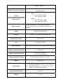
Specifications
Data Rates Supported
1, 2, 5.5, and 11 Mbps
Network Standard
IEEE 802.11b
Uplink
10BaseT Ethernet
Frequency Band
2.4 to 2.497 GHz (subject to local regulations)
Network Architecture Types
Infrastructure
Wireless Medium
Direct Sequence Spread Spectrum (DSSS)
Media Access Protocol
Carrier sense multiple access with collision avoidance
(CSMA/CA)
Modulation
Operating Channels
Receive Sensitivity
•
•
•
DBPSK @1 Mbps
DQPSK @ 2 Mbps
CCK @ 5.5 and 11 Mbps
•
•
•
•
11 channels (US, Canada))
13 channels (ETSI)
4 channels (France)
14 channels (Japan)
•
•
1 Mbps: –94 dBm
2 Mbps: –91 dBm
•
•
Available Transmit Power Settings
100 mW / 200 mW
Indoor:
• 50 m (164 ft) @ 11 Mbps
• 110 m (360 ft) @ 1 Mbps
Range
(typical @ 99-mW transmit power
setting, including 1.95 dBi diversity
dipole antenna)
EMC Certification
5.5 Mbps: –87 dBm
11 Mbps: –84 dBm
Outdoor:
• 240 m (787 ft) @ 11 Mbps
• 600 m (1968 ft) @ 1 Mbps
FCC 47CFR15 subpart C (15.247) and Class B device
ETSI 300-328/301-489-17 (General EMC requirement for RF
equipment)
Antenna
Two soldered dipole antennas
Security
IEEE 802.11 WEP (Wired Equivalent Privacy)
Encryption Key Length
64-bit, 128-bit
Filter
MAC Address Filtering
Status Indicators
LED Light provide status of: Power, Wireless LAN, and Ethernet.
Automatic Configuration Support
DHCP client
Remote Configuration Support
HTTP for configuration
TFTP for firmware upgrade
Dimensions WxHxD (mm/inch)
161mm x 30mm x 119mm (6.3 ‘’x1.2 ‘’x4.7’’)
Weight
195g (6.87oz)
Environmental
•
•
•
Operating temperature: 0 oC to 40 oC (32 oC to 104 oC)
Storage temperature: -20 oF to 70 oF (-4 oF to 158 oF)
Humidity: 10 to 90% (non-condensing)
Input Power Requirements
DC 5V 2A
Warranty
One year
1.3
•
•
•
•
•
•
Product Kit
The Access Point Kit contains the following items:
One 802.11b WLAN Access Point
One Power Adapter
One Quick Installation Guide
One User Manual
One Ethernet Straight LAN cable
Note: If any item listed above is damaged or missing, please contact your dealer immediately.
System Requirements
To accomplish a successful operation of your 802.11b WLAN Access Point, we suggest the following items are
required:
•
•
•
•
•
1.4
•
•
•
•
•
One or more PCs (desktop or notebook) with Ethernet interface.
TCP/IP protocol must be installed on all PCs.
Network cables. Use standard 10/100BaseT network (UTP) cables with RJ45 connectors.
To use the Wireless Access Point, all wireless devices must be compliant with the IEEE 802.11b specifications.
Microsoft Internet Explorer 5.0 or later or Netscape Navigator 4.7 or later.
System Requirements
One or more PCs (desktop or notebook) with Ethernet interface.
TCP/IP protocol must be installed on all PCs. (Refer to User Manual for additional information)
Network cables. Use standard 10/100BaseT network (UTP) cables with RJ45 connectors.
All wireless devices must be compliant with the IEEE 802.11B specifications.
Microsoft Internet Explorer 5.0 or later or Netscape Navigator 4.7 or later.
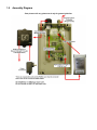
1.5
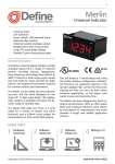
Assembly Diagram
*Part pictures will vary, please use it only for general guide line.
EzBridge 802.11B Basics
This section is consisted of three parts. You will learn the guise of the hardware, including the ports and LEDs, and the
installation of Access Point.
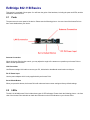
2.1
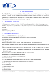
Ports
The ports are on the rear panel of the device. Please see the following picture – the rear view of the Access Point to
learn more details about your device.
Antenna Connection
When the Access Point begins to work, you may adjust the angle of the antenna or reposition your Access Point to
obtain a better performance.
LAN Connection
Use Ethernet straight LAN cable to connect your PC, hub/switch or broadband router/modem to this port.
DC 5V Power Input
Use the power adapter which is only supplied with your Access Point.
Set to Default Button
When you press this button, the Access Point will reboot and reset current settings to factory default settings.
2.2
LEDs
The 802.11b WLAN Access Point includes three types of LED indicators. Please check the following picture – the front
view of the Access Point and table to obtain the information on the LED indicators on your Access Point.
LED
Power
Status
On
Off
Blinking
Function
Power on.
No power.
Blinking: Wireless LAN is transmitting.
WLAN
On
On: Wireless LAN connection is active.
Ethernet
2.3
Off
Blinking
On
Off
Off: Wireless LAN connection is not active.
Blinking: Wired LAN is transmitting.
On: Wired LAN is active.
Off: Wired LAN is not active.
Installation
Preparation for Installation
Before you actually install your 802.11b WLAN Access Point, please ensure that all the items listed in “1.4 System
Requirements” are prepared, and then choose the place with the consideration of power outlet and network connection
to install the Access Point.
To avoid causing any damage to the Access Point hardware device, please do not power up the device before you
start to connect it to the port on your PC.
Also notice that a full installation of your Access Point includes not only the hardware installation but also the network
configuration on your PC. Check the following section -“Hardware Installation” and the next chapter - “Configuring
Windows for IP Networking” to obtain complete details.
Hardware Installation
Follow the procedures below to fully install your Access Point hardware device:
1. Select a suitable place on the network to install the Access Point. Ensure the Access Point and the DSL/cable
modem are powered off. For best wireless reception and performance, the Access Point should be positioned
in a central location with minimum obstructions between the Access Point and the PCs.
2. Connect one end of Ethernet cable to Access Point and the other to switch or hub, and then the Access Point
will be connected to the 10/100 Network.
3. Connect the power adapter to the power socket on your Access Point.
4. Last but not the least, check the LEDs on the Access Point to confirm if the status is okay.
5. Now the hardware installation is complete, and you may proceed to the next chapter –“Configuring Windows
for IP Networking” for instruction on setting up network configurations.
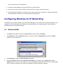
Configuring Windows for IP Networking
To establish a communication between your PCs and the EzBridge, you will need to set up a static IP address for your
computer first. This section helps you configure the network settings for your operating system. Please follow the
procedures below to complete the settings:
2.4
Windows 98/Me
1.
Click Start on the taskbar and choose Control Panel from the submenu of Settings.
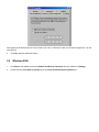
2.
Select Network to open the Network dialog box, and then under the Configuration tab, select the TCP/IP
protocol for your network card.
3.
Click Properties to open the TCP/IP Properties dialog box.
4.
Click the IP Address tab and choose Specify an IP address. For example, type in 192.168.1.X in the IP
Address (where X is any free IP number from 1-254, excluding 99) area and 255.255.255.0 in the Subnet Mask
area. To ensure the system is now using the IP address you specify, restart the computer.
Note: Again the IP address must be in the format of 192.168.1.x. Where the value of X should be ranged from 1 to 254
excluding 99.
5.
2.5
Click OK, and then restart the system.
Windows 2000
1.
Click Start on the taskbar and choose Network and Dial-up Connection from the submenu of Settings.
2.
Double-click the Local Area Connection open the Local Area Connection Properties box.
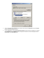
3.
Select the Internet Protocol (TCP/IP) for your network card, and then click Properties to open the Internet
Protocol (TCP/IP) Properties dialog box.
4.
Under the General tab, choose Use the following IP address, and then specify an IP address. For example,
type in 192.168.1.X in the IP Address (where X is any free IP number from 1-254, excluding 99) area and
255.255.255.0 in the Subnet Mask area.
Note: Again the IP address must be in the format of 192.168.1.x. Where the value of X should be ranged from 1 to 254
excluding 99.
5.
2.6
Click OK.
Windows XP
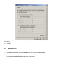
1.
Click Start on the taskbar and choose Network from the submenu of Control Panel.
2.
Right-click the Local Area Connection icon and then choose Properties from the menu. You should see the
Local Area Connection Properties dialog box shown below.
3.
Select the Internet Protocol (TCP/IP) for your network card, and then click Properties.
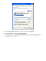
4.
In the opened dialog box, choose Use the following IP address
5.
Under the General tab, choose Use the following IP address, and then specify an IP address. For example,
type in 192.168.1.X in the IP Address (where X is any free IP number from 1-254, excluding 99) area and
255.255.255.0 in the Subnet Mask area.
Note: Again the IP address must be in the format of 192.168.1.x. Where the value of X should be ranged from 1 to 254,
excluding 99.
Click OK.
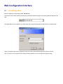
Web Configuration Interface
3.1
Client Bridge Mode
Default IP Address in Client Bridge Mode: 192.168.1.99
To access the web control interface please open up a browser window and type in the factory default IP address in the
URL.
Then press Enter on your keyboard, you will see the login prompt window appear similar like the one shown below.
There is no default User name or Password. Leave User Name and Password field blank and then click OK.
Note: You may set a new password by clicking the Admin tab after you enter the Web Configuration page
Info
Firmware Revision
Current firmware revision loaded on the EzBridge.
Connected to SSID
SSID in which the EzBridge is associated to.
Using Channel
If the EzBridge is associated with an AP or Bridge it will display the channel used.
MAC address of Access Point
The associated AP’s MAC address.
Current transmission rate (Mbits/s)
Displays the current maximum transmission rate established by the wireless link.
Current communications quality (%)
The communications quality is calculated in a ratio percentage based on the signal strength and noise.
MAC address of the wireless card
The MAC address of the wireless card plugged inside the EzBridge.
Current IP address
IP address assign on the unit.
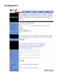
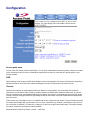
Configuration
Operation Mode
Ad-hoc: An 802.11 networking framework in which devices or stations communicate directly with each other, without
the use of an access point (AP). Use this mode if there is no wireless infrastructure or where services are not required.
Infrastructure: An 802.11 networking framework in which devices communicate with each other by first going through
an Access Point (AP). This mode is the default factory setting.
SSID
Network Name is also known as SSID, which stands for Service Set Identifier. Any client in Infrastructure mode has to
indicate the SSID of an Access Point to start accessing the service from behind such as internet access.
Channel
Channels are important to understand because they affect the overall capacity of your Wireless LAN. A channel
represents a narrow band of radio frequency. A radio frequency modulates within a band of frequencies; as a result,
there is a limited amount of bandwidth within any given range to carry data. It is important that the frequencies do not
overlap or else the throughput would be significantly lowered as the network sorts and reassembles the data packets
sent over the air.
These are the only 3 channels out of the 11 available that do not overlap with one another. To avoid interference within
the network with multiple APs, set each AP to use one of the 3 channels (e.g. Channel 1) and then the other AP to be
one of the other 2 channels (i.e. Channel 6 or Channel 11) within the range of the wireless radio. This simple method
will reduce interference and improve network reliability.
802.11b/g Wireless Channel Frequency Range: 2.4 GHz – 2.497 GHz
802.11b/g Non-overlapping Channel Frequency Ranges
•
•
•
Channel 1 = 2.401 GHz – 2.423 GHz
Channel 6 = 2.426 GHz – 2.448 GHz
Channel 11 = 2.451 GHz – 2.473 GHz
Americas: Wireless Channels 1 – 11
Asia: Wireless Channels 1 – 14
Europe: Wireless Channels 1 – 13
Transmission Rate
This option indicates the transmission rate of the bridge. Specify the rate according to the speed of your wireless
network from the list. Most of the time the default setting Best (automatic) should be selected for best performance.
You may want to adjust the setting manually If your link quality and signal strength is usually low or high to get the best
performance.
WEP enabled
Short for Wired Equivalent Privacy, a security protocol for wireless local area networks (WLANs) defined in the 802.11b
standard. WEP is designed to provide the same level of security as that of a wired LAN. This option will enable the
WEP security authenticator.
WEP Key Length
64 bit (10 Hex Digit)
WEP Key type
Example
64-bit WEP with 10 hexadecimal digits
('0-9', 'A-F')
Key1= 123456789A
Key2= 23456789AB
Key3= 3456789ABC
Key4= 456789ABCD
128 bit (26 Hex Digit)
WEP Key type
Example
128-bit WEP with 26 hexadecimal digits
('0-9', 'A-F')
Key1= 112233445566778899AABBCDEF
Key2= 2233445566778899AABBCCDDEE
Key3= 3344556677889900AABBCCDDFF
Key4= 44556677889900AABBCCDDEEFF
WEP Key 1 – 4
Follow the example above to setup either character or hexadecimal key according to the key length.
WEP key to use
Select one pre-defined WEP key to use for authentication.
Deny unencrypted data
When the WEP authentication is enabled any unencrypted data will be blocked from getting pass this unit from the
receiving side.
Shared key Authentication
Shared key authentication supports authentication of stations as either a member of those who know a shared secret
key or a member of those who do not. Shared key authentication is not secure and is not recommended for use. It
verifies that an authentication-initiating station has knowledge of a shared secret. This is similar to pre-shared key
authentication for Internet Protocol security (IPSec). The 802.11 standard currently assumes that the shared secret is
delivered to the participating wireless clients by means of a more secure channel that is independent of IEEE 802.11.
In practice, a user manually types this secret for the wireless AP and the wireless client.
Shared key authentication uses the following process:
1. The authentication-initiating wireless client sends a frame consisting of an identity assertion and a request for
authentication.
2. The authenticating wireless node responds to the authentication-initiating wireless node with challenge text.
3. The authentication-initiating wireless node replies to the authenticating wireless node with the challenge text
that is encrypted using WEP and an encryption key that is derived from the shared key authentication secret.
4. The authentication result is positive if the authenticating wireless node determines that the decrypted
challenge text matches the challenge text originally sent in the second frame. The authenticating wireless node
sends the authentication result.
Because the shared key authentication secret must be manually distributed and typed, this method of authentication
does not scale appropriately in large infrastructure network mode, such as corporate campuses.
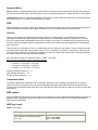
Stations
Bridge Table
The bridge table is a list of all devices connected to the EzBridge through the Ethernet side. Information such as IP and
MAC address are displayed for each device. The table can hold as many bridged devices as the memory on the
EzBridge is allowed.
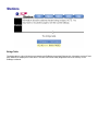
Administration
User name
This is the name of the user account that will be used to configure the EzBridge. (Default User name: blank)
Administrator password
The password used by the user account. (Default password: blank)
SNMP enabled
Option to enable or disable SNMP support.
The components of SNMP network management fall into three categories:
1. Managed devices (such as a switch)
2. SNMP agents and MIBs, including Remote Monitoring (RMON) MIBs, which run on managed devices
3. SNMP management applications, such as CiscoWorks2000, which communicate with agents to get statistics
and alerts from the managed devices
Note: An SNMP management application, together with the computer it runs on, is called a network management
system (NMS).
Read only community
The SNMP Read-only Community string is like a user id or password that allows access to a router's or other device's
statistics. InterMapper sends the community string along with all SNMP requests. If the community string is correct, the
device responds with the requested information. If the community string is incorrect, the device simply discards the
request and does not respond.
Factory default setting for the read-only community string is set to "public". It is standard practice to change all the
community strings so that outsiders cannot see information about the internal network. (In addition, the administrator
may also employ firewalls to block any SNMP traffic to ports 161 and 162 on the internal network.)
Change this value to have InterMapper use the new string when querying SNMP devices.
Read/Write community
Gives read and write access to all objects in the MIB, but does not allow access to the community strings
IP Information
IP Address Mode
•
Static
o Manually setup an IP for this device.
•
DHCP
o Set up the bridge as a DHCP client which will pick up an IP from a DHCP server.
IP address
The default Client Bridge Mode IP address: 192.168.1.99
Subnet mask
The factory subnet default value is 255.255.255.0
Gateway
The factory gateway default address is 192.168.1.1
Device name
This is the name that the bridge will use to identify itself to external configuration and IP address programs. This is not
the same as the SSID. It is okay to leave this blank if you are not using these programs.
Allow upgrade uploads
This option determines if the EzBridge can be re-flashed with a firmware into the on board memory.
Cloning bridge
If enabled the MAC Address from the first Ethernet client that transmits data through the EzBridge will be used. This
will mean that the client MAC address will become the alias address to the Bridge.
Commands
This section has functions that will allow the EzBridge to Reboot and Reset the system configuration to factory default.
Reboot bridge
This function will restart the EzBridge.
Reset to factory defaults
This function will reset all software setting back to factory default values.
3.2
Access Point Mode
Default IP Address in Access Point Mode: 192.168.1.90
To access the web control interface please open up a browser window and type in the factory default IP address in the
URL.
Then press Enter on your keyboard, you will see the login prompt window appear similar like the one shown below.
There is no default User name or Password. Leave User Name and Password field blank and then click OK.
Note: You may set a new password by clicking the Admin tab after you enter the Web Configuration page
Info
Firmware Revision
Current firmware revision loaded on the EzBridge.
MAC address of Access Point
The MAC address of the wireless card plugged inside the EzBridge.
Current IP address
IP address assign on the unit.
Associations
This section will show a list of all the wireless clients currently associating with the EzBridge AP. Each associated
clients’s MAC address and idel time in minutes will also be listed.
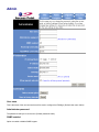
Configuration
Access point name
You can name this access point for identification. You can leave it blank without entering anything. However, the name
for the access point will be useful for identification especially when there are more than one access points in your
wireless network.
SSID
Network Name is also known as SSID, which stands for Service Set Identifier. Any client in Infrastructure mode has to
indicate the SSID of an Access Point to start accessing the service from behind such as internet access.
Channel
Channels are important to understand because they affect the overall capacity of your Wireless LAN. A channel
represents a narrow band of radio frequency. A radio frequency modulates within a band of frequencies; as a result,
there is a limited amount of bandwidth within any given range to carry data. It is important that the frequencies do not
overlap or else the throughput would be significantly lowered as the network sorts and reassembles the data packets
sent over the air.
These are the only 3 channels out of the 11 available that do not overlap with one another. To avoid interference within
the network with multiple APs, set each AP to use one of the 3 channels (e.g. Channel 1) and then the other AP to be
one of the other 2 channels (i.e. Channel 6 or Channel 11) within the range of the wireless radio. This simple method
will reduce interference and improve network reliability.
Wireless Channel Frequency Range: 2.4 GHz – 2.497 GHz
Channel 1 = 2401 Hz – 2423 Hz
Channel 6 = 2426 Hz – 2448 Hz
Channel 11 = 2451 Hz – 2473 Hz
Americas: Wireless Channels 1-11
Asia: Wireless Channels 1 – 14
Europe: Wireless Channels 1-13
Basic rates (Mbit/s)
This option controls the speed limit for management packets such as association, authentication etc.
Supported rates (Mbit/s)
This option controls the speed limit for all data packets.
Transmission rate (Mbits/s)
This option indicates the transmission rate of the AP. Specify the rate according to the speed of your wireless network
from the list. Most of the time the default setting Best (automatic) should be selected for best performance. You may
want to adjust the setting manually If your link quality and signal strength is usually low or high to get the best
performance.
Preamble type
Define the Preamble type as Long, Short or Both. The Short preamble option presents a better throughput
performance; however, this depends upon the supportiveness of your wireless LAN card. It is recommended to use the
Short preamble type if similar equipment and firmware are used. For universal compatibility, use the Long preamble
type.
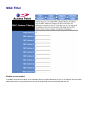
MAC Filter
Enable access control
If enabled, this feature will allow you to associate devices by MAC addresses from up to 16 different units. Any MAC
addresses that are not programmed into the list will be blocked out from associating with the unit.
Advanced
Maximum associated stations
This the maximum number of wireless clients that can be associated at any one time.
Fragmentation threshold
Fragmentation Threshold is the maximum length of the frame, beyond which payload must be broken up (fragmented)
into two or more frames. Collisions occur more often for long frames because sending them occupies the channel for a
longer period of time, increasing the chance that another station will transmit and cause collision. Reducing
Fragmentation Threshold results in shorter frames that "busy" the channel for shorter periods, reducing packet error
rate and resulting retransmissions. However, shorter frames also increase overhead, degrading maximum possible
throughput, so adjusting this parameter means striking a good balance between error rate and throughput.
RTS threshold
RTS Threshold is the frame size above which an RTS/CTS handshake will be performed before attempting to transmit.
RTS/CTS asks for permission to transmit to reduce collisions, but adds considerable overhead. Disabling RTS/CTS
can reduce overhead and latency in WLANs where all stations are close together, but can increase collisions and
degrade performance in WLANs where stations are far apart and unable to sense each other to avoid collisions (aka
Hidden Nodes). If you are experiencing excessive collisions, you can try turning RTS/CTS on or (if already on) reduce
RTS/CTS Threshold on the affected stations.
Beacon period
In wireless networking, a beacon is a packet sent by a connected device to inform other devices of its presence and
readiness.
When a wirelessly networked device sends a beacon, it includes with it a beacon interval, which specifies the period of
time before it will send the beacon again. The interval tells receiving devices on the network how long they can wait in
low-power mode before waking up to handle the beacon. Network managers can adjust the beacon interval, usually
measured in milliseconds (ms) or its equivalent, kilo microseconds (Kmsec).
DTIM interval
Delivery Traffic Indication Message. A DTIM is a signal sent as part of a beacon by an access point to a client device in
sleep mode, alerting the device to a packet awaiting delivery. A DTIM interval, also known as a Data Beacon Rate, is
the frequency at which an access point's beacon will include a DTIM. This frequency is usually measured in
milliseconds (ms) or its equivalent, kilo microseconds (Kmsec).
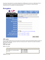
Encryption
WEP enabled
Short for Wired Equivalent Privacy, a security protocol for wireless local area networks (WLANs) defined in the 802.11b
standard. WEP is designed to provide the same level of security as that of a wired LAN. This option will enable the
WEP security authenticator.
WEP Key Length
64 bit (10 Hex Digit)
WEP Key type
Example
64-bit WEP with 10 hexadecimal digits
('0-9', 'A-F')
Key1= 123456789A
Key2= 23456789AB
Key3= 3456789ABC
Key4= 456789ABCD
128 bit (26 Hex Digit)
WEP Key type
Example
128-bit WEP with 26 hexadecimal digits
('0-9', 'A-F')
Key1= 112233445566778899AABBCDEF
Key2= 2233445566778899AABBCCDDEE
Key3= 3344556677889900AABBCCDDFF
Key4= 44556677889900AABBCCDDEEFF
WEP Key 1 – 4
Follow the example above to setup either character or hexadecimal key according to the key length.
WEP key to use
Select one pre-defined WEP key to use for authentication.
Deny unencrypted data
When the WEP authentication is enabled any unencrypted data will be blocked from getting pass this unit from the
receiving side.
Shared key Authentication
Shared key authentication supports authentication of stations as either a member of those who know a shared secret
key or a member of those who do not. Shared key authentication is not secure and is not recommended for use. It
verifies that an authentication-initiating station has knowledge of a shared secret. This is similar to pre-shared key
authentication for Internet Protocol security (IPSec). The 802.11 standard currently assumes that the shared secret is
delivered to the participating wireless clients by means of a more secure channel that is independent of IEEE 802.11.
In practice, a user manually types this secret for the wireless AP and the wireless client.
Shared key authentication uses the following process:
5. The authentication-initiating wireless client sends a frame consisting of an identity assertion and a request for
authentication.
6. The authenticating wireless node responds to the authentication-initiating wireless node with challenge text.
7. The authentication-initiating wireless node replies to the authenticating wireless node with the challenge text
that is encrypted using WEP and an encryption key that is derived from the shared key authentication secret.
8. The authentication result is positive if the authenticating wireless node determines that the decrypted
challenge text matches the challenge text originally sent in the second frame. The authenticating wireless node
sends the authentication result.
Because the shared key authentication secret must be manually distributed and typed, this method of authentication
does not scale appropriately in large infrastructure network mode, such as corporate campuses.
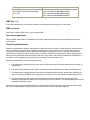
Admin
User name
This is the name of the user account that will be used to configure the EzBridge. (Default User name: blank)
Administrator password
The password used by the user account. (Default password: blank)
SNMP enabled
Option to enable or disable SNMP support.
The components of SNMP network management fall into three categories:
1. Managed devices (such as a switch)
2. SNMP agents and MIBs, including Remote Monitoring (RMON) MIBs, which run on managed devices
3. SNMP management applications, such as CiscoWorks2000, which communicate with agents to get statistics
and alerts from the managed devices.
Note: An SNMP management application, together with the computer it runs on, is called a network management
system (NMS).
Read only community
The SNMP Read-only Community string is like a user id or password that allows access to a router's or other device's
statistics. InterMapper sends the community string along with all SNMP requests. If the community string is correct, the
device responds with the requested information. If the community string is incorrect, the device simply discards the
request and does not respond.
Factory default setting for the read-only community string is set to "public". It is standard practice to change all the
community strings so that outsiders cannot see information about the internal network. (In addition, the administrator
may also employ firewalls to block any SNMP traffic to ports 161 and 162 on the internal network.)
Change this value to have InterMapper use the new string when querying SNMP devices.
Read/Write community
Gives read and write access to all objects in the MIB, but does not allow access to the community strings
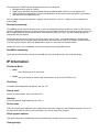
IP Information
IP Address Mode
•
Static
o Manually setup an IP for this device.
•
DHCP
o Set up the bridge as a DHCP client which will pick up an IP from a DHCP server.
IP address
The default Client Bridge Mode IP address: 192.168.1.99
Subnet mask
The factory subnet default value is 255.255.255.0
Gateway
The factory gateway default address is 192.168.1.1
Device name
This is the name that the bridge will use to identify itself to external configuration and IP address programs. This is not
the same as the SSID. It is okay to leave this blank if you are not using these programs.
Allow upgrade uploads
This option determines if the EzBridge can be re-flashed with a firmware into the on board memory.
Cloning bridge
If enabled the MAC Address from the first Ethernet client that transmits data through the EzBridge will be used. This
will mean that the client MAC address will become the alias address to the Bridge.
Commands
This section has functions that will allow the EzBridge to Reboot and Reset the system configuration to factory default.
Reboot bridge
This function will restart the EzBridge.
Reset to factory defaults
This function will reset all software setting back to factory default values.
Appendix A: Warranty Policy
Limited Warranty
All Teletronics’ products warranted to the original purchaser to be free from defects in materials and workmanship
under normal installation, use, and service for a period of one (1) year from the date of purchase.
Under this warranty, Teletronics International, Inc. shall repair or replace (at its option), during the warranty period, any
part that proves to be defective in material of workmanship under normal installation, use and service, provided the
product is returned to Teletronics International, Inc., or to one of its distributors with transportation charges prepaid.
Returned products must include a copy of the purchase receipt. In the absence of a purchase receipt, the warranty
period shall be one (1) year from the date of manufacture.
This warranty shall be voided if the product is damaged as a result of defacement, misuse, abuse, neglect, accident,
destruction or alteration of the serial number, improper electrical voltages or currents, repair, alteration or maintenance
by any person or party other than a Teletronics International, Inc. employee or authorized service facility, or any use in
violation of instructions furnished by Teletronics International, Inc.
This warranty is also rendered invalid if this product is removed from the country in which it was purchased, if it is used
in a country in which it is not registered for use, or if it is used in a country for which it was not designed. Due to
variations in communications laws, this product may be illegal for use in some countries. Teletronics International, Inc.
assumes no responsibility for damages or penalties incurred resulting from the use of this product in a manner or
location other than that for which it is intended.
IN NO EVENT SHALL TELETRONICS INTERNATIONAL, INC. BE LIABLE FOR ANY SPECIAL, INCIDENTAL OR
CONSEQUENTIAL DAMAGES FOR BREACH OF THIS OR ANY OTHER WARRANTY, EXPRESSED OR IMPLIED,
WHATSOEVER.
Some states do not allow the exclusion or limitation of special, incidental or consequential damages, so the above
exclusion or limitation may not apply to you.
This warranty gives you specific legal rights, and you may also have other rights that vary from state to state.
Appendix B: RMA Policy
Product Return Policy
It is important to us that all Teletronics’ products are bought with full confidence. If you are not 100% satisfied with any
product purchased from Teletronics you may receive a prompt replacement or refund, subject to the terms and
conditions outlined below.
IMPORTANT: Before returning any item for credit or under warranty repair, you must obtain a Return Merchandise
Authorization (RMA) number by filling out the RMA form. Products will not be accepted without an RMA number. All
products being shipped to Teletronics for repair / refund / exchange must be freight prepaid (customer pays for
shipping). For all under warranty repair/replacement, Teletronics standard warranty applies.
30-Day full refund or credit policy:
1. Product was purchased from Teletronics no more than 30 day prior to the return request.
2. All shipping charges associated with returned items are non-refundable.
3. Products are returned in their original condition along with any associated packaging, accessories, mounting
hardware and manuals. Any discrepancy could result in a delay or partial forfeiture of your credit.
Unfortunately Teletronics cannot issue credits for:
1. Products not purchased from Teletronics directly. If you purchased from a reseller or distributor you must contact
them directly for return instructions.
2. Damaged items as a result of misuse, neglect, or improper environmental conditions.
3. Products purchased direct from Teletronics more than 30 days prior to a product return request.
To return any product under 1 year warranty for repair/replacement, follow the RMA procedure.
Appendix C: Regulatory Information
Statement of Conditions
We may make improvements or changes in the product described in this documentation at any time. The information
regarding to the product in this manual are subject to change without notice.
We assume no responsibility for errors contained herein or for direct, indirect, special, incidental, or consequential
damages with the furnishing, performance, or use of this manual or equipment supplied with it, even if the suppliers
have been advised of the possibility of such damages.
Electronic Emission Notices
This device complies with Part 15 of the FCC Rules. Operation is subject to the following two conditions:
(1) This device may not cause harmful interference.
(2) This device must accept any interference received, including interference that may cause undesired operation.
FCC Information
The Federal Communication Commission Radio Frequency Interference Statement includes the following paragraph:
The equipment has been tested and found to comply with the limits for a Class B Digital Device, pursuant to part 15 of
the FCC Rules. These limits are designed to provide reasonable protection against harmful interference in a residential
installation. This equipment generates, uses and can radiate radio frequency energy and, if not installed and used in
accordance with the instruction, may cause harmful interference to radio communication. However, there is no
guarantee that interference will not occur in a particular installation. If this equipment does cause harmful interference
to radio or television reception, which can be determined by turning the equipment off and on, the user is encouraged
to try to overcome the interference by one or more of the following measures:
-
Reorient or relocate the receiving antenna.
Increase the separation between the equipment and receiver.
Connect the equipment into an outlet on a circuit different from that to which the receiver is connected.
Consult the dealer or an experienced radio/TV technician for help.
The equipment is for home or office use.
Important Note
FCC RF Radiation Exposure Statement: This equipment complies with FCC RF radiation exposure limits set forth for
an uncontrolled environment. This equipment should be installed and operated with a minimum distance of 20cm
between the antenna and your body and must not be co-located or operating in conjunction with any other antenna or
transmitter.
Caution: Changes or modifications not expressly approved by the party responsible for compliance could void the
user's authority to operate the equipment.
R&TTE Compliance Statement
This equipment complies with all the requirements of the Directive 1999/5/EC of the European Parliament and the
Council of 9 March 1999 on radio equipment and telecommunication terminal equipment (R&TTE)and the mutual
recognition of their conformity. The R&TTE Directive repeals and replaces in the directive 98/13/EEC. As of April 8,
2000.
European Union CE Marking and Compliance Notices
Products intended for sale within the European Union are marked, which indicates compliance with the applicable
directives identified below. This equipment also carries the Class 2 identifier.
With the Conformité Européene (CE) and European standards and amendments, we declare that the equipment
described in this document is in conformance with the essential requirements of the European Council Directives,
standards, and other normative documents listed below:
73/23/EEC Safety of the User (article 3.1.a)
89/336/EEC Electromagnetic Compatibility (article 3.1.b)
1999/5/EC (R&TTE) Radio and Telecommunications Terminal Equipment Directive.
EN 60950 2000 Safety of Information Technology Equipment, Including Electrical Business Equipment.
EN 300 328 V1.4.1(2003) Electromagnetic compatibility and Radio spectrum Matters (ERM); Wideband Transmission
systems;Data transmission equipment operating in the 2,4 GHz ISM band and using spread spectrum modulation
techniques;Harmonized EN covering essential requirements under article 3.2 of the R&TTE Directive.
EN 301 489-1, V1.4.1(2002); EN 301 489-17, V1.2.1(2002) – Electromagnetic compatibility and radio spectrum
matters (ERM); electromagnetic compatibility (EMC) standard for radio equipment and services: Part 1: Common
technical requirements; Part 17: Part 17: Specific conditions for 2,4 GHz wideband transmission systems and5 GHz
high performance RLAN equipment
Warning: According to ERC/REC 70-30 appendix 3 National Restrictions, annex 3 Band A “RLANs and HIPERLANs.”
See list of 802.11b/g restrictions for specific countries under the heading “European Economic Area Restrictions” as
below.
English
This product follows the provisions of the European Directive 1999/5/EC.
Danish
Dette produkt er i overensstemmelse med det europæiske direktiv 1999/5/EF
Dutch
Dit product is in navolging van de bepalingen van Europees Directief 1999/5/EC.
Finnish
Tämä tuote noudattaa EU-direktiivin 1999/5/EY määräyksiä.
French
Ce produit est conforme aux exigences de la Directive Européenne 1999/5/CE.
Appendix D: Contact Information
Need to contact Teletronics?
Visit us online for information on the latest products and updates to your existing products at:
http://www.teletronics.com
Can't find information about a product you want to buy on the web? Do you want to know more about networking with
Teletronics products?
Give us a call at: 301-309-8500 Or fax your request in to: 301-309-8551
Don't wish to call? You can e-mail us at: [email protected]
If any Teletronics product proves defective during its warranty period, you can email the Teletronics Return
Merchandise Authorization department to obtain a Return Authorization Number at: [email protected]
(Details on Warranty and RMA issues can be found in Appendix A and B)
Appendix E: Important Outdoor Install Guide
This EZBridge unit requires additional grounding and protection prior to installation to ensure trouble free operation
and warranty compliance. Please follow the process below to ensure you are protected against flash memory
corruption, premature hardware failure, and/or earth-ground potential issues.
Cause and Effect
It has been recently discovered that by simply grounding the NEMA4 enclosure containing the EZBridge PCB,
operation with unstable power and un-filtered AC lines can be made more reliable and not cause damage to the circuit.
(Most customers have circuits shared with electric motors, solenoids, fluorescent lighting, and/or dimmers,
transformers, etc. These devices compromise the neutral when there is no earth-ground available.) Many field-tested
units have been damaged by inadequate grounding at the installation site as well as voltage spikes on the neutral side
of the AC line, resulting in corrupted flash memory and ultimately an un-recoverable error condition. To prevent this
from impacting your EZBridge and to maintain your Teletronics’ warranty, you must follow the simple process set forth
below prior to initial power-up.
Tools and Materials Required:
1. #2 Philips Screwdriver
2. Teletronics’ supplied grounding wire, screw, washer, and lockwasher.
*Customer can use their own cable if desired; however the potential must not be more than 2-Ohms of resistance from
enclosure to ground-point.
Procedure:
1.
2.
3.
4.
5.
6.
7.
8.
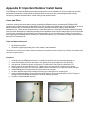
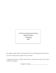
Carefully place the EZBridge face down on a solid work surface, with mounting holes pointing up.
Insert self-threading screw into the detent 1.65” (42mm) from top of bridge and 1.00” (25.5mm)
from the side. (Please use picture as reference.) The diameter of the screw hole should be 0.15”
and the depth of the hole should be 0.35”. Tighten screw to a snug but do not tight fit, then remove.
Clean debris from screw-hole, place lock washer first then electrical ring on top thread, screw until tight.
Install EZBridge per mounting instructions and continue to next step.
Connect opposite end of the grounding wire with ring to earth-ground or mounting pole.
If using the optional Teletronics surge protected PoE Inserter, connect grounding lug from PoE Inserter to
earth-ground and EZBridge ground wire to the same earth-ground point.
9. Continue normal installation process.
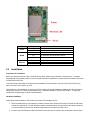
Appendix F: EzBridge Model Information and Compatible
Teletronics Wireless Cards
EzBridge has two PCB versions
PCB labeled with 29AB025XXX – Older EzBridge PCBs
•
Uses Firmware 1.7.0 and below (Do not load firmware revision above 1.7.0) Power input is 7.5 DCV
through the PoE connection.
PCB labeled with 29AB234XXX – Newer EzBridge PCBs
•
Uses Firmware 2.0.0 and above (Do not load firmware revision below 2.0.0). Power input is 9 DCV
through the PoE connection.
Note: Power input will vary depending on the length of the PoE run and the quality of the Ethernet cable (24 AWG) and
connectors.
Compatible Teletronics Wireless Cards
Teletronics 30mW PCMCIA card Model XI-300*, XI-325*, XI-330
Teletronics 100mW PCMCIA card Model XI-325H
Teletronics 200mW PCMCIA card Model XI-325HP
(Compatiable only with PCB 29AB234XXX, requires 9 VDC)
Teletronics 100mW PCMCIA card Standard Card
* Discontinued
Appendix G: Troubleshooting
Please check the following If you no longer can access the EzBridge through the web interface:
1. Clear out the arp (type arp -d under the command prompt) and internet cache.
2. Try to access the unit with a different browser such as the firefox.
3. Try manually setting your ethernet adapter to 10Mbits half duplex speed.
4. Try it from another computer with a different brand of network card. If the EzBridge is hooked up to a Hub/Switch try
and change to another brand of Hub/Switch as there are sometimes compatibility issues between the EzBridge
Ethernet port and some brand of NICs and Hubs/Switches. (Please report all incompatibility issues to
[email protected]).
5. Make sure your IP address is setup correctly on the same network as that of the EzBridge.
6. Re-seat the PCMCIA card
7. Do a hard reset on the unit by pressing down the reset bottom. Continue to hold the reset bottom down while
powering down the unit. Continue to hold the reset bottom down while turning the power back on. Hold down the reset
bottom for another 10 seconds at this point, then release. This would ensure a proper hard reset on the EzBridge.
8. Make sure that you're using the proper cabling to connect to the EzBridge. You'll need to use a cross over cable
between the Net side of the PoE and the computer. ODU side should be used to plug into the EzBridge with a straight
through cable.
9. Please try the above solutions and let us know if this unit is still giving you a problem.
10. Open up the NEMA4 box, bypass the waterproof Ethernet adapter and connect a computer directly into the PCB
with a crossover cable. If this revives the unit it means that either the water proof Ethernet adapter is bad or the
Ethernet cable between the adapter and the PCB is bad.
11. Double check all cabling to make sure that nothing is loose or any cables are in non-working condition with a cable
tester.
12. If the unit is revived and there is a weak or no signal strength you may have a bad RF pigtail or Radio card.
13. Make sure that the pigtail is attached to the right port of the radio card. Please consult to the user manual for
farther detail.
14. Try another PoE
Make sure that you are using the proper power adapter and double check the adapter with an ohmmeter to see if the
unit is providing the proper voltage output. Consult the user manual to find out the proper voltage input is needed.
(Warning: Some EzBridges comes with a power input plug on the PCBs. Please do not plug the power adapter directly
onto the PCB of the EzBridges, as all power input plugs build into the PCBs are rated at 5V)
Appendix H: Glossary
802.1x - The standard for wireless LAN authentication used between an AP and a client. 802.1x with EAP will initiate
key handling.
Ad-Hoc Network - The wireless network based on a peer-to-peer communications session. Also referred to as AdHoc.
Access Point - Access points are stations in a wireless LAN that are connected to an Ethernet hub or server. Users
can roam within the range of access points and their wireless device connections are passed from one access point to
the next.
Authentication - Authentication refers to the verification of a transmitted message's integrity.
Beacon - In wireless networking, a beacon is a packet sent by a connected device to inform other devices of its
presence and readiness.
Beacon interval - When a wirelessly networked device sends a beacon, it includes with it a beacon interval, which
specifies the period of time before it will send the beacon again. The interval tells receiving devices on the network
how long they can wait in low-power mode before waking up to handle the beacon. Network managers can adjust the
beacon interval, usually measured in milliseconds (ms) or its equivalent, kilo microseconds (Kmsec).
BSS - Basic Service Set. When a WLAN is operating in infrastructure mode, each access point and its connected
devices are called the Basic Service Set.
BSSID - The unique identifier for an access point in a BSS network. See SSID for more details.
DHCP - DHCP (Dynamic Host Configuration Protocol) software automatically assigns IP addresses to client stations
logging onto a TCP/IP network, which eliminates the need to manually assign permanent IP addresses.
DSSS (Direct Sequence Spread Spectrum) - Method of spreading a wireless signal into wide frequency bandwidth.
Dynamic IP Address - An IP address that is automatically assigned to a client station in a TCP/IP network, typically by
a DHCP server.
DNS (Domain Name System): System used to map readable machine names into IP addresses
DTIM - DTIM (Delivery Traffic Indication Message) provides client stations with information on the next opportunity to
monitor for broadcast or multicast messages.
DTIM interval - A DTIM interval, also known as a Data Beacon Rate, is the frequency at which an access point's
beacon will include a DTIM. This frequency is usually measured in milliseconds (ms) or its equivalent, kilo
microseconds (Kmsec).
ESS - Extended Service Set. ESS is the collective term for two or more BSSs that use the same switch in a LAN.
ESSID - Extended Service Set Identifier. An ESSID is the unique identifier for an ESS. See SSID for more details.
Filter - Filters are schemes, which only allow specified data to be transmitted. For example, the router can filter
specific IP addresses so that users cannot connect to those addresses.
Firmware: Programming inserted into programmable read-only memory, thus becoming a permanent part of a
computing device.
Fragmentation - Refers to the breaking up of data packets during transmission.
Gateway – Is the place where two or more networks connect
IBSS - Independent Basic Service Set. See ad-hoc network
Infrastructure Mode - When a wireless network functions in infrastructure mode, every user communicates with the
network and other users through an access point; this is the typical way corporate WLANs work. An alternative is adhoc mode, but users would have to switch to infrastructure mode to access a network's printers and servers.
ISP - An ISP is an organization providing Internet access service via modems, ISDN (Integrated Services Digital
Network), and private lines.
LAN(Local Area Network): A group of computers and peripheral devices connected to share resources.
MAC (Medium Access Control) Address: A unique number that distinguishes network cards.
MTU - MTU (Maximum Transmission/Transfer Unit) is the largest packet size that can be sent over a network.
Messages larger than the MTU are divided into smaller packets.
NAT - NAT (Network Address Translation - also known as IP masquerading) enables an organization to present itself to
the Internet with one address. NAT converts the address of each LAN node into one IP address for the Internet (and
vice versa). NAT also provides a certain amount of security by acting as a firewall by keeping individual IP addresses
hidden from the WAN.
Preamble - Preamble refers to the length of a CRC (Cyclic Redundancy Check) block that monitors’ communications
between roaming wireless enabled devices and access points.
Protocol - A standard way of exchanging information between computers.
RADIUS (Remote Authentication Dial In User Service): A server that issues authentication key to clients.
RAM (Random Access Memory): Non-permanent memory.
RIP - RIP (Routing Information Protocol) is a routing protocol that is integrated in the TCP/IP protocol. RIP finds a route
that is based on the smallest number of hops between the source of a packet and its destination.
Router - A router is a device that forwards data packets along networks. The device is connected to at least two
networks, commonly two LANs or WANs or a LAN and an ISP. Routers are located at gateways, the places where two
or more networks connect and use headers and forwarding tables to determine the best path for forwarding the
packets. And they use protocols such as ICMP to communicate with each other and configure the best route between
any two hosts. Very little filtering of data is done through routers.
Roaming - The ability to use a wireless device while moving from one access point to another without losing the
connection.
RTS - RTS (Request To Send) is a signal sent from the transmitting station to the receiving station requesting
permission to transmit data.
Server - Servers are typically powerful and fast machines that store programs and data. The programs and data are
shared by client machines (workstations) on the network.
Static IP Address - A permanent IP address is assigned to a node in a TCP/IP network. Also known as global IP.
Subnet Mask - Subnet Masks (SUBNET work masks) are used by IP protocol to direct messages into a specified
network segment (i.e., subnet). A subnet mask is stored in the client machine, server or router and is compared with an
incoming IP ad-dress to determine whether to accept or reject the packet.
SSID - SSID (Service Set Identifier) is a security measure used in WLANs. The SSID is a unique identifier attached to
packets sent over WLANs. This identifier emulates a password when a wireless device attempts communication on the
WLAN. Because an SSID distinguishes WLANS from each other, access points and wireless devices trying to connect
to a WLAN must use the same SSID.
TCP/IP - TCP/IP (Transmission Control Protocol/Internet Protocol) is the main Internet communications protocol. The
TCP part ensures that data is completely sent and received at the other end. Another part of the TCP/IP protocol set is
UDP, which is used to send data when accuracy and guaranteed packet delivery are not as important (for example, in
real-time video and audio transmission).
TFTP (Trivial File Transfer Protocol) - Simple form of FTP (File Transfer Protocol), which Uses UDP (User Datagram
Protocol), rather than TCP/IP for data transport and provides no security features.
TKIP (Temporal Key Integrity Protocol): An encryption method replacing WEP.TKIP uses random IV and frequent key
exchanges.
UDP (User Datagram Protocol) - A communication method (protocol) that offers a limited amount of service when
messages are exchanged between computers in a network. UDP is used as an alternative
to TCP/IP.
Uplink: Link to the next level up in a communication hierarchy.
UTP (Unshielded Twisted Pair) cable - Two or more unshielded wires twisted together to form a cable.
Virtual Servers - Virtual servers are client servers (such as Web servers) that share resources with other virtual
servers (i.e., it is not a dedicated server).
WEP (Wired Equivalent Privacy) - An encryption method based on 64 or 128bit algorithm.
WLAN - WLANs (Wireless LANs) are local area networks that use wireless communications for transmitting data.
Transmissions are usually in the 2.4 GHz band. WLAN devices do not need to be lined up for communications like
infrared devices. WLAN devices use access points, which are connected to the wired LAN and provide connectivity to
the LAN. The radio frequency of WLAN devices is strong enough to be transmitted through non-metal walls and
objects, and can cover an area up to a thousand feet. Laptops and notebooks use wireless LAN PCMCIA cards while
PCs use plug-in cards to access the WLAN.