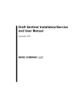
1
1
Merlin
Universal Indicator
›
›
›
›
›
›
›
›
Universal input
22V excitation
Smart, simple, USB powered setup
Optional relay outputs
Optional isolated analogue output
Designed for harsh environments
Large 0.8" super-bright display
Flexible 32 point linearization table
General Description
The Merlin universal digital indicator accepts
analogue inputs from a range of industrial
sensors, including: process, temperature,
flow, frequency, and voltage from 200mV to
300V. It features a wide range power supply
that suits both AC mains and 24V DC applications, and supplies the excitation required
for common sensors and transmitters.
The Merlin can be scaled into any engineering unit, and the result displayed on the
large 0.8” 4 digit super-bright LED display.
Auto ranging is available to increase the dynamic range of viewable data.
The Merlin R2A adds two Form A 3 Amp
relays for a variety of control and alarm
functions, and a 4-20mA active output for
retransmission to PLCs and SCADA systems.
The unit boasts a 1 minute setup time using
the Define Toolbox configuration software.
All functions are explained expertly in the
dynamic sidebar help - perfect for the novice
starting out who can use it to learn about
industrial applications, or the expert who
wants to save commissioning time.
The Merlin has been designed for harsh industrial environments. With an IP65 sealed
bezel and extensive testing of noise effects
to and beyond CE requirements, the meter
provides a tough and reliable application
solution.
Quick start
Hardware
Install (p6)
Software
Install (p7)
Copyright © 2015 Define Instruments
Software
Setup (p9)
Wiring (p12)
MER-MAN-15V04 (1005)
2
CONTENTS
Contents ................................................. 2
5.4 - Power Supply .......................... 13
Order Codes ............................................ 2
5.5 - Sensor Input ............................ 14
Safety Notices ......................................... 3
5.6 - Analogue Output .................... 14
Symbol Definitions ................................. 3
5.7 - Relay Outputs .......................... 14
1 - Specifications .................................... 3
5.8 - User Input ............................... 14
1.1 - General Meter Specifications .... 3
6 - Input Types ..................................... 15
1.2 - Display ....................................... 5
6.1 - Thermocouple Input ............... 15
1.3 - Case Dimensions ....................... 5
6.2 - RTD Input ................................ 16
2 - Hardware Installation ...................... 6
6.3 - NTC Input ................................ 17
2.1 - Installation Instructions ............ 6
6.4 - Current Input .......................... 18
2.2 - Installation Environment .......... 6
6.5 - Voltage Input .......................... 19
3 - Software Installation ....................... 7
6.6 - Digital Pulse ............................. 21
4 - Software Configuration ................... 9
Using ToolBox
6.7 - Potentiometer Input ............... 22
4.1 - Bridge Key ................................. 9
7 - Maintenance & Service .................. 24
4.2 - Using ToolBox ......................... 10
7.1 - Calibration ............................... 24
4.3 - ToolBox Interface Overview ..... 11
7.2 - Troubleshooting ...................... 24
5 - Wiring ............................................. 12
7.3 - Service ..................................... 25
5.1 - Wiring Overview ..................... 12
A - Appendix A - EMC Test Results ...... 25
5.2 - EMC Installation Guidelines .... 12
B - Appendix B - Warranty & ............... 27
User's Responsibility
5.3 - Back Panel ............................... 13
6.8 - AC Current Sensor ................... 23
ORDER CODES
MER
Merlin
– UV – R2A
Universal
Voltage
Output
(Optional)
Merlin
MER
Universal Indicator
Universal Voltage
UV
24–250V AC / 19.5–250V DC
Output
R2A
2 x relay outputs, 1 x analogue output (4–20mA)
MER-MAN-15V04 (1005)
Copyright © 2015 Define Instruments
3
SAFETY NOTICES
For your safety and the prevention of damage to the Merlin unit and other equipment connected to it, please read complete instructions prior to installation and
operation of the Merlin, and carefully observe all safety regulations and instructions. Consult this manual carefully in all cases where hazard symbols are marked
on your Merlin unit.
Use of this instrument in a manner not specified by the manufacturer may compromise the protection provided by the instrument. This instrument should not be used
to directly drive valves, motors, or other actuators, unless equipped with appropriate safeguards.
It is the responsibility of the user to indentify potential hazards that may arise in
the event of a fault to unit, and implement safeguards for the prevention of harm
to persons or equipment. The safety of any system incorporating this unit is the
responsibility of the assembler of the system.
Symbol definitions
CAUTION
Risk of electric shock
Please refer to user manual.
Both direct and alternating current.
CAUTION
Equipment protected throughout by
DOUBLE INSULATION or REINFORCED
INSULATION.
Risk of danger
Please refer to user manual.
1
SPECIFICATIONS
1.1 - General meter specifications
Power
Analogue input
Power supply 24–250V AC / 19.5–250V DC,
47–63Hz, 6VA max
Input Universal (see Section 6 for full input
specifications and wiring)
Isolation 2,300Vrms for 1min to all inputs
and outputs
Excitation power
Excitation 22V ±10% (25mA max)
Copyright © 2015 Define Instruments
MER-MAN-15V04 (1005)
4
Relay output
OPTIONAL
Type 2x Form A relays
Isolation to sensor and user input commons 2,300Vrms for 1min
Working voltage 240Vrms
Contact rating
One Relay energized: 3amps @ 120/240V AC
or 28V DC (resistive load)
3amps max total current with both relays
energized
Life expectancy 100K cycles min at full load
rating
Environmental conditions
Operating humidity 5–85%RH max
(non-condensing)
Operating temperature -10 to 50°C
Storage temperature -20 to 60°C
Altitude Up to 2,000m
Certifications & compliances
EN 61326-1 Immunity to Industrial Locations
Emission CISPR 11 Class A (EN 61326)
One user input is available on R2A model
only. It can be programmed as a manual
relay reset switch or a latching switch
Safety requirements for electrical equipment for measurement control, and laboratory use:
EN 61010-1 General Requirements
EN 61010-2-030 Particular Requirements
for Testing and Measuring Circuits
Max continuous input 20V DC
UL Listed File Number E473114
Isolation to sensor input common
Not isolated
IP65 Enclosure rating (face only)
User input
OPTIONAL
Construction
Analogue output
OPTIONAL
Type 1x 4–20mA or 20–4mA DC
Isolation to sensor and user input commons 1,400Vrms for 1min
Working voltage 125V
Max output drive 20mA (600Ω max load at
12V DC)
Accuracy/repeatability 0.05% of FSO
Resolution 1μA
Temperature drift 30ppm/°C typical
Panel mount enclosure Rated for IP65
indoor use. Installation Category II, Pollution
Degree 2. Flame resistant. Panel gasket and
mounting clips included.
Dimensions
48 x 95 x 62 mm (1.89 x 3.74 x 2.44")
Cutout area 45 x 92mm ±.5 (1.77 x 3.62" ±.02)
Space behind panel 80mm (3.15") minimum
space required behind panel (includes space
for connectors/wiring)
Weight 195g (6.87oz)
Powered Self-powered (active)
MER-MAN-15V04 (1005)
Copyright © 2015 Define Instruments
5
1.2 - Display
Digits 4 digit red LED, 0.8" (20mm),
7-segment characters
Display range -1999 to 9999
Annunciators 2x setpoint indicator
LEDs (R2A model only)
IP65 sealed front bezel
1.3 - Case dimensions
91mm (3.58")
62mm (2.44")
22mm
(0.87")
4mm (0.16")
48
mm
44
mm
Connectors
& wiring
(1.89") (1.73")
95mm (3.74")
107mm (4.21")
Copyright © 2015 Define Instruments
80mm (3.15") minimum
depth required behind panel
MER-MAN-15V04 (1005)
6
2
HARDWARE INSTALLATION
2.1 - Installation instructions
The Merlin is designed to be mounted into
an enclosed panel, and meets IP65 requirements when properly installed.
A
Prepare the Panel Cutout to 92x45mm
±.5 (3.62x1.77" ±.02) as shown below.
B
Remove the Mounting Clips from the
Merlin unit.
C
Slide the Panel Gasket over the rear of
the unit to the back of the Bezel.
Panel
D
From the front of the panel, insert the
Merlin into the Panel Cutout. Holding
the unit in place, engage the Mounting
Clips so that the tabs snap into place
over the notches on the case.
E
To achieve a proper seal, tighten the
Screws evenly until the unit sits firmly
against the panel (torque to approximately 70N-cm [6.2 in-lbs]). Do not overtighten the screws.
Bezel
Panel
Gasket
Mounting
Clips
Panel Cutout
92mm ±.5
(3.62″ ±.02)
45mm ±.5
(1.77″ ±.02)
Screws
2.2 - Installation environment
The Merlin should be installed in a location
that does not exceed the maximum operating temperature, and at a safe distance from
other devices that generate excessive heat.
The installation environment should provide
good air circulation to the unit.
MER-MAN-15V04 (1005)
The bezel, plastic casing and product label
may be cleaned, if required, using a soft,
damp cloth and neutral soap product.
Continuous exposure to direct sunlight
should be avoided, as this may accelerate
the aging process of the bezel.
Copyright © 2015 Define Instruments
7
3
SOFTWARE INSTALLATION
ToolBox offers a smart, no-fuss setup experience for your Merlin universal indicator. It features
USB powered programming (no power supply required!) and has been designed to simplify
and speed up configuration.
You must install ToolBox before connecting the Merlin to your computer. If you have already
connected the meter using the Bridge Key, please disconnect it before continuing.
A
Download the latest version of ToolBox from
www.defineinstruments.com/toolbox
For ease of access, we recommend saving the install file on your desktop. If you
can't find the install file, check whether your browser has saved it in your 'Downloads' folder.
B
Extract the install file from the zip folder. Right-click on the zip folder and choose 'Extract
All', (or extract the file using another extraction utility of your choice).
Fig 1
C
Double-click on the extracted .msi install
file. This will launch the ToolBox installer.
Depending on your security settings, a
'Security Warning' dialogue may appear.
If you see the security message, click
'Run'.
Fig 2
Copyright © 2015 Define Instruments
MER-MAN-15V04 (1005)
8
D
The ToolBox setup wizard will
launch (Fig 3).
Click 'Next' to get started.
E
The wizard will also ask for
confirmation that you wish to
begin the installation.
Click 'Next' to continue.
F
Next the wizard will prompt
you to select an installation
folder (Fig 4). You may accept
the default installation folder,
or select an alternative location by clicking 'Browse'.
Fig 3
Click 'Next' to continue.
G
The install wizard will now install ToolBox, and a progress
bar will appear. Please wait.
This process usually takes 2-3
minutes.
If you are using
Windows with 'User
Account Control'
enabled, you may
be asked for permission to continue the
installation (Fig 5).
Click 'Yes'.
(Note that this
dialogue may cause
a slight delay to
the installation
process.)
H
Fig 4
Fig 5
When ToolBox has finished installing, 'Installation Complete'
will appear (Fig 6). Click 'Close'.
The installer will place an icon
on your desktop for easy access to ToolBox.
The downloaded .zip and .msi
installer files are no longer
needed, and may be deleted.
Fig 6
MER-MAN-15V04 (1005)
Copyright © 2015 Define Instruments
9
4
SOFTWARE CONFIGURATION USING TOOLBOX
4.1 - Bridge Key
Install the ToolBox software (see Section 3) before connecting the Merlin to your PC.
Then connect the Merlin to your computer's USB port using the Bridge Key (supplied separately), as shown below. The interface cable connects to the USB programming jack on the
unit's back panel (see 5.3D). A USB extension cable is supplied for your use if required - this is
often used for convenience in accessing USB ports located at the back of the computer.
Merlin
Universal
Indicator
Interface
Cable
USB Bridge Key
USB Extension Cable
(If Necessary)
PC Connection
INSTALL SOFTWARE FIRST!
CAUTION
Risk of damage to equipment or PC
Ensure that all connections between the Bridge Key and your Merlin are secure. Connecting your indicator with cables that are not firmly 'pushed in' will result in connection faults,
and in extreme cases could cause damage to your computer.
Do not uplug the Bridge Key or any connecting cables while ToolBox is busy applying
changes to the Merlin. This may cause loss of settings, or unexpected unit behaviour.
CAUTION
Not UL approved
The Bridge Key is sold separately to the Merlin and has not been certified for UL.
Copyright © 2015 Define Instruments
MER-MAN-15V04 (1005)
10
4.2 - Using ToolBox
The ToolBox software enables full configuration of your Merlin universal indicator. To set up
your indicator, only the Bridge Key is required - you do not need to supply power.
ToolBox features a comprehensive help panel that will guide you through the setup of your
Merlin universal indicator. Helpful hints and explanations will appear when you adjust a
setting using the ToolBox controls.
There are three main navigation pages/tabs:
›
›
›
Input/Output: Input mode/range, Scaling/offset, Display, Retransmission scaling
Setpoints: Alarm control/mode, Setpoint activation points, advanced modes
Advanced: Load/save configuration, Create configuration certificate
A
Double-click the ToolBox icon on your desktop to launch the ToolBox program.
B
With the Merlin connected to your computer's USB port (see 4.1), click the green
'Connect' button. This will scan your computer's Com ports and automatically connect to
your device.
Connection problems?
ToolBox will auto-detect and connect to the Merlin when you click the 'Connect' button. If you
have problems establishing a connection, please check the following:
›
›
›
Ensure that all connections between the device and your computer are secure. The main
interface cable must be fully inserted into both the USB programmer and the Merlin's
programming port. Press firmly.
Try disconnecting and reconnecting the Merlin USB, or using a different USB port on
your computer.
Disconnect any additional compatible devices. The software auto-detect feature does
not work if multiple Merlins are connected simultaneously.
MER-MAN-15V04 (1005)
Copyright © 2015 Define Instruments
11
4.3 - ToolBox interface overview
Main Navigation Tabs
Input/Output, Setpoints, and Advanced configuration pages. (ToolBox will detect your
meter outputs and will only display relevant tabs.)
Control Area
Main control area for configuring your meter.
Any changes made in this area will bring up
the Apply Bar (see below)
Connection Panel
Disconnect button
Connection status
Live display
Apply Bar
Help Panel
Appears if you have made any changes in the
Control Area. ToolBox will not allow you to browse
to a new tab in the Main Navigation with unapplied changes to your configuration.
Diagrams, explanations, and
helpful tips will automatically
appear in this panel as you
configure your meter.
Copyright © 2015 Define Instruments
MER-MAN-15V04 (1005)
12
5
WIRING
5.1 - Wiring overview
Electrical connections are made via plug in
terminal blocks at the rear of the meter. All
conductors must conform to the meter's
voltage and current ratings, and be suitably
rated for the expected temperature range to
be incurred.
When wiring the meter, check all connections by comparing the terminal numbers
shown on the meter label against the appropriate wiring diagrams in this manual (5.3–
5.8 and Section 6), or in the Define ToolBox
software. Strip the wire, leaving around
0.25" (6mm) of bare lead exposed. If you are
using stranded wire, this should be tinned
with solder. Insert the lead into the correct
plug in the correct position, and tighten
until the wire is secure. Verify tightness by
pulling on the wire.
Follow all local codes and regulations when
wiring and installing the meter. Each terminal is rated to accept one wire from #14
AWG (2.5mm) to #20 AWG. However it is
also possible to accept two #18 AWG wires,
or up to four #20 AWG wires.
CAUTION
All field wiring must rated at a
minimum of 70°C (158°F).
5.2 - EMC installation guidelines
The Merlin has been designed to cope
with large EMC disturbances. This has been
achieved by continual testing and improvement of filtering and layout techniques over
many years.
of near field radiated noise. The metal
enclosure acting as a faraday cage will
shunt this radiation to ground and away
from the Merlin. Further improvements
can be made with this type of noise by
increasing the physical distance from
the power devices. For example, increasing the control box distance from 6” to
12” from the noise source will reduce
the noise seen by the control box by a
factor of 4. Probably the cheapest and
best results in this situation could be
obtained by adding RC snubbers to the
contactors or power switches.
The Merlin not only meets CE noise requirements, but surpasses them in many tests.
(For full details and test results, please see
Appendix A.)
However in some applications with less
than optimum installations and large power
switching, the EMC performance of the
Merlin can be further improved, by:
A
Installing the Merlin in an earthed metal
enclosure. This is particularly useful if
the control box is mounted close to
large power switching devices like contactors. Every switching cycle there is a
possibility of generating a large amount
MER-MAN-15V04 (1005)
B
Using shielded cable on sensitive input
and control signal lines. Good results can
be obtained by grounding the shields to
the metal enclosure close to the entry
point. All cables act as aerials and pick
up unwanted R.F. radiated signals and
Copyright © 2015 Define Instruments
13
noise; the earthed shield acts as a faraday cage around the cables, shunting
the unwanted energy to ground. Shields
can also help with capacitively coupled
noise typically found in circumstances
when signal cable is laid on top of noisy
switching power cables. Of course in
this case you are better off to keep separate signal and power lines.
C
meter. This is particularly useful if there
are long cable runs, or the unit is close
to radiating sources such as two way
radios.
D
Laying cable on earthed cable trays
can also help reduce noise seen by the
The relay outputs of the Merlin have
built in MOVs to help reduce EMI when
switching inductive loads. EMI can further be reduced at the load by adding
snubbers for AC signals or a flyback diode for DC coils.
5.3 - Back panel
The back panel of the Merlin may have up to 5
screw terminals (A–F) and 1 USB programming jack
(D). Ports C–F are installed on the R2A model only.
A
Sensor input
(Pins 1–6, Section 6)
B
Power supply
(Pins 7–8, See 5.4)
C
Analogue output
(Pins 9–10, See 5.6)
D
USB programming jack
(See Section 4)
E
User input
(Pins 11–12, See 5.8)
F
Relay outputs
(Pins 13–16, See 5.7)
5.4 - Power supply
See 5.3B, pins 7–8
The Merlin features a wide range Power Supply that suits both AC
mains and 24V DC applications. The Merlin uses a full bridge rectifier, so
it is not sensitive to polarity for DC power inputs.
POWER
CAUTION
Risk of electric shock.
AC power supplied to the meter must be protected by a UL approved 10A circuit breaker. DC power supplied to the meter must
be protected by a UL approved 1A, 250V fuse.
Copyright © 2015 Define Instruments
24–250V
AC
19.5–250V
DC
MER-MAN-15V04 (1005)
14
5.5 - Sensor input
See 5.3A, pins 1–6
The Sensor Input terminal can be wired to suit numerous input types. See Section 6 for input
wiring, or refer to the ToolBox help panel as you are configuring the unit.
5.6 - Analogue output (If installed)
See 5.3C, pins 9–10
If your model includes Analogue Output, wire it as shown (right).
ANALOG
OUTPUT
4–20mA
The analogue output can be scaled to suit your application using the
ToolBox software.
5.7 - Relay outputs (If installed)
SETPOINTS
See 5.3F, pins 13–16
If your model includes Relay Outputs, wire them as shown (right). The
setpoints can be configured using ToolBox for a variety of alarm or control functions.
5.8 - User input (If installed)
SP 1 SP 2
USER
INPUT
See 5.3E, pins 11–12
UDŽ 1
Com
If your model includes Relay Outputs, then a User Input is also provided. This can be connected to a switch as shown, to perform manual
relay reset and latching functions. These options are fully configurable
using the ToolBox software.
CAUTION
The User Input common is NOT isolated from the Sensor Input.
In order to preserve the safety of the meter application, the User
Input common must be suitably isolated from hazardous live earth
referenced voltages; or the User Input common must be at protective earth ground potential.
If not, hazardous live voltage may be present on the User Input
and the User Input common terminals. Appropriate considerations
must then be given to the potential of the User Input common
with respect to earth common.
MER-MAN-15V04 (1005)
Copyright © 2015 Define Instruments
15
6
INPUT TYPES
CAUTION
Risk of electric shock. Dangerous and lethal voltages may be present on the terminals of
the meter. Please take appropriate precautions to ensure safety.
CAUTION
Risk of danger. The sensor input can potentially float to dangerous and unexpected voltages depending on what external circuit it is connected to. Appropriate considerations
must be given to the potential of the sensor input with respect to earth common.
6.1 - Thermocouple input
Thermocouple types
B, E, J, K, N, R, S, T
Input impedance 1MΩ min
TC lead resistance 100Ω max
Cold junction comp. -10 to 70°C
Accuracy E, J, K, N, T: < ±1°C.
B, R, S: < ±2°C.
Temperature (thermocouple)
Temperature drift
E, J, K, N, T: < ±0.05°C/C.
B, R, S: < ±0.2°C/C.
Sensor break output drive
Function high upscale/low downscale
CJC error < ±1°C
Response time 400msec
Supported thermocouple types/ranges
The thermocouple is one of the most
common temperature sensors used in
industry. It relies on the Seebeck coefficient between dissimilar metals.
K
-200°C (-328°F)
1372°C (2502°F)
B
400°C (752°F)
1800°C (3272°F)
E
-200°C (-328°F)
800°C (1472°F)
The thermocouple type is selected with
reference to the application temperature range and environment. The most
common thermocouple types for general
purpose applications are J and K type.
J
-200°C (-328°F)
1000°C (1832°F)
R
-50°C (-58°F)
1760°C (3200°F)
S
-50°C (-58°F)
1760°C (3200°F)
T
-200°C (-328°F)
400°C (752°F)
N
-200°C (-328°F)
1300°C (2372°F)
TC
Copyright © 2015 Define Instruments
MER-MAN-15V04 (1005)
16
6.2 - RTD input
RTD input Pt100 or Pt1000 DIN 3-wire
type (2-wire can be used with offset trim)
Pt100 lead wire resistance 50Ω/wire max.
0.02% FSO offset error per Ω of lead resistance mismatch
Pt1000 lead wire resistance 20Ω/wire
max. 0.002% FSO offset error per Ω of lead
resistance mismatch
Sensor current 0.3mA nominal
Sensor break output drive
Function high upscale/low downscale
Accuracy Better than 0.2°C
Temperature drift <0.007°C/C
Response time 400msec
Temperature (RTD)
The RTD (standing for Resistance
Temperature Device) is highly stable and
accurate, and is fast becoming the most
popular temperature sensor in industry.
Often referred to as Pt100 and Pt1000,
the Pt represents platinum (the dominant
metal in its construction), and 100/ 1000 is
the resistance in ohms at 0°C.
RTD 3 Wire PT100/1000
Link
Supported RTD types/ranges
Pt100
-200°C (-328°F)
320°C (608°F)
Pt1000
-200°C (-328°F)
320°C (608°F)
MER-MAN-15V04 (1005)
RTD 2 Wire PT100/1000
Copyright © 2015 Define Instruments
17
6.3 - NTC input
NTC -50 to 125°C (various thermistors)
Accuracy Better than 0.4°C
Sensor types 10K Beta 3984/3435
Temperature drift <50ppm/°C
Response time 100msec
Temperature (NTC)
NTC (Negative Temperature Coefficient),
is a particular type of thermistor.
NTC's are popular in the HVAC industry
due to their low cost, but have a limited
temperature range which makes them less
popular in general industry.
The biggest issue with their general
acceptance is that there is no standard
that covers inter operability between different thermistor manufacturers.
Copyright © 2015 Define Instruments
N.T.C 10,000Ω
Supported NTC types/ranges
10K Beta 3984
-55°C (-67°F)
125°C (257°F)
10K Beta 3435
-50°C (-58°F)
110°C (230°F)
MER-MAN-15V04 (1005)
18
6.4 - Current input
Range 0/4–20.000mA
Max over-range 50mA DC continuous
Excitation +22V DC, 25mA max
Linearity and repeatability
<±0.02% FSO typical
USB prog zero 0–±99% of span
Field prog span 1μA–24mA DC
Input resistance 10Ω
Temperature drift <50ppm/°C
Response time 100msec
0/4–20mA DC
0/4–20mA DC, 3 or 4 wire transmitter
0/4–20mA DC is the most commonly used
analogue signal in industry, and is universally accepted. As a current loop, it is unaffected by voltage drops in cables, and can
be transmitted over long distances without signal degradation.
The meter can provide up to 25mA to
power an external 3 or 4 wire transmitter,
and at the same time measure the signal.
Current 0/4−20mA
3 Wire Transmitter 0/4−20mA
+ Signal 0/4-20mA
Supply +22V DC 25mA max
4–20mA DC, loop powered
transmitter
The meter can provide power to a loop
powered transmitter, and at the same
time measure the signal. This configuration is ideal for when there is a long distance between the sensor and the meter.
4 Wire
Transmitter
0/4−20mA
+ Signal 0/4-20mA
Supply +22V DC 25mA max
2 Wire 4−20mA
Loop Powered
Transmitter
MER-MAN-15V04 (1005)
Copyright © 2015 Define Instruments
19
6.5 - Voltage input
Ranges ±200mV, –200mV to 1V, 0–10V,
±10V, –10 to 30V, 0–300V
USB prog zero 0–±99% of span
USB prog span 95% of FSO
Input resistance 1MΩ min
Linearity and repeatability
<±0.02% FSO typical
(0–10V= <±0.05%; 0–300V= <±0.1%)
Temperature drift <50ppm/°C
Response time 100msec
±200mV DC
0–10V DC
For low signal applications the meter supports a ±200mV DC range. Typical applications include measuring large DC currents
using external current shunts.
0–10V DC is a common process signal generated by transmitters, meters and PLCs.
±200mV DC
It would normally be scaled into engineering units by the meter.
0−10V DC
-200mV to 1V DC
±10V DC
A -200mV to 1V range is provided for
interfacing to sensors and other electronic apparatus that provide this output.
±10V DC is a common process signal generated by transmitters, meters and PLCs. It
would normally be scaled into engineering
units by the meter.
−200mV to 1V DC
±10V DC
Copyright © 2015 Define Instruments
MER-MAN-15V04 (1005)
20
-10 to 30V DC
0–300V DC
This is a general purpose voltage measuring range, typically used to measure battery voltages, power supply outputs etc.
This higher voltage general purpose range
is typically used to measure battery voltages, power supply outputs, etc.
−10 to 30V DC
0−300V DC
CAUTION
Risk of electric shock
Exercise extreme caution when
handling high voltage inputs.
CAUTION
Rated voltage between pins 5 &
6 and earth is 300V DC max.
MER-MAN-15V04 (1005)
Copyright © 2015 Define Instruments
21
6.6 - Digital pulse
Frequency range 0–2000.0Hz
Sensors Open collector (NPN, PNP)
Excitation +22V DC, 25mA max
Response time 100msec
General frequency mode
Software modes General frequency, Flow
rate (pulse), or RPM (pulse)
Linearity and repeatability 0.05%
Temperature drift <50ppm/°C
NPN open collector output
General Frequency mode allows an NPN or
PNP input (up to 2KHz) to be measured
and scaled to any engineering unit.
The meter can also provide up to 25mA to
power an external device.
N.P.N Open
Collector Output
Flow rate mode
Flow Rate mode enables an input from an
NPN or PNP paddle type flow meter to be
converted to a flow rate. The input signal
(up to 2KHz) is converted into a flow rate
by programming the unit with the sensor
manufacturer's K-factor value.
The meter can also provide up to 25mA
to power a 3 wire NPN paddle type flow
sensor.
+22V DC, 25mA max
N.P.N Open Collector Output
With Excitation
RPM mode
ToolBox RPM mode enables an input from
an NPN or PNP proximity sensor to be converted to an RPM (Revs Per Minute) value.
The input signal (up to 2KHz) is converted
into RPM by programming the unit with
the pulses per revolution value.
The meter can also provide up to 25mA to
power a 3 wire NPN proximity sensor.
Copyright © 2015 Define Instruments
PNP open collector output
P.N.P Open
Collector Output
MER-MAN-15V04 (1005)
22
6.7 - Potentiometer input
Potentiometer input 3-wire
Field prog span 0.1–100%
Excitation voltage Variable
Linearity and repeatability
<±0.05% FSO typical
Potentiometer resistance <1kΩ low pot;
1–4kΩ med pot; 4–20kΩ high pot
Field prog zero 0–90% of span
Response time 100msec
Temperature drift <50ppm/°C
3 wire potentiometer
A 3 wire potentiometer is typically used
to measure position. The low, medium
or high potentiometer range can be programmed to your unit using the ToolBox
software.
These ranges must be calibrated using the
two point calibration method.
Potentiometer
Low (<1kΩ)
MER-MAN-15V04 (1005)
Potentiometer
Med (1−4kΩ)
Potentiometer
High (4−20kΩ)
Copyright © 2015 Define Instruments
23
6.8 - AC current sensor
Sensor type Current transformer (Define
Instruments ACCS-420/010)
Amperage range Header selectable
100/150/200A; Overload 175/300/400A
respectively (continuous)
Output (Representing 0–100% of full scale
input range)
ACCS-420 = 4–20mA DC loop powered
ACCS-010 = 0–10V DC
Power supply
ACCS-420 = Loop powered, 15–36V DC
ACCS-010 = Self powered
Accuracy 1% of full scale
Response time 250ms (10–90%)
Isolation voltage 2,000V
Frequency 50–60Hz
AC current sensors
Jump Range
The meter accepts input from a Define
Instruments AC current sensor. Set the
jumper on the top of the current sensor
to the desired current range, as shown
(right).
0–100A
AC Current Sensor
4−20mA
Powered by the
Merlin
Copyright © 2015 Define Instruments
0–150A
0–200A
AC Current
Sensor
0−10V
Signal powered
MER-MAN-15V04 (1005)
24
7
MAINTENANCE & SERVICE
7.1 - Calibration
The meter has been fully calibrated at the factory, and can be recalibrated in software using
Define ToolBox (see Section 4). Scaling to convert the input signal to a desired display value is
also done using ToolBox.
If the meter appears to be indicating incorrectly or inaccurately, refer to troubleshooting
before attempting to calibrate the meter. When recalibration is required (generally every 2
years), it should only be performed by qualified technicians using appropriate equipment.
Calibration does not change any user programmed parameters. However, it may affect the
accuracy of the input signal values previously stored.
7.2 - Troubleshooting
Problem
Resolution
No display
Check power connections.
c.err
Internal Comms Error
Try re-starting unit. If the problem is intermittent, this error could be caused by
an EMC issue. Please refer to 5.2 for potential remedies.
Er.CL
Analogue Output Calibration Error
Factory calibration of analogue output is corrupt or missing. Return unit to factory for re-calibration.
ER.Fl
Display Flash Error
Settings such as decimal point, scaling, and brightness will be lost. Reconnect to
Define ToolBox (see Section 4) and set up the meter again.
er.01 to10
Analogue Input Error
Error type indicated by a numerical error code (01-10). Please return to factory
for repair.
Sens
Sensor Error
Sensor is missing or faulty. Check your sensor wiring.
over
A/D Overflow
Check your sensor wiring. If the sensor wiring is correct, check the signal level.
undr
A/D Underflow
Check your sensor wiring. If the sensor wiring is correct, check the signal level.
For further assistance, please contact technical support using the contact details listed at the
end of this document.
MER-MAN-15V04 (1005)
Copyright © 2015 Define Instruments
25
7.3 - Service
Please return this product to the manufacturer if servicing is required.
THE MERLIN HAS NO USER SERVICEABLE PARTS.
For further assistance, please contact technical support using the contact details listed at the
end of this document.
A
APPENDIX A - EMC TEST RESULTS
The Merlin has been designed to cope with large EMC disturbances. This has been achieved by
constantly testing and improving filtering and layout techniques over many years. The Merlin
offers superior R.F. filtering on all inputs, outputs and power supplies, when compared to
most competing products.
The Merlin not only meets CE noise requirements, but surpasses them in many tests. Furthermore, all testing was performed in plastic enclosures without shielded cabling.
Immunity - Enclosure Ports
Phenomenon
Basic Standard Test Value
Performance Criteria
EM Field
IEC 61000-4-3
10Vm (80Mhz to 1GHz)
Meets Criterion A
3V/m (1.4GHz to 2.7Ghz)
Electrostatic
Discharge (ESD)
IEC 61000-4-2
4KV/8KV contact/air
Meets Criterion A (Note 1)
Meets NAMUR NE 21 recommendation
Immunity - Signal Ports
Phenomenon
Basic Standard Test Value
Performance Criteria
Conducted RF
IEC 61000-4-6
3V(150Khz to 80Mhz)
Meets Criterion A
Burst
IEC 61000-4-4
1KV (5/50ns,5Khz)
1KV(5/50ns,100Khz)
Meets Criterion A (Note 1)
Meets NAMUR NE 21 recommendation
Surge
IEC 61000-4-5
1KV L-E
Meets Criterion A (Note 1)
Immunity - AC power
Phenomenon
Basic Standard Test Value
Performance Criteria
Conducted RF
IEC 61000-4-6
3V (150Khz to 80Mhz)
Meets Criterion A
Burst
IEC 61000-4-4
2KV (5/50ns, 5Khz) L-N
1KV (5/50ns, 5Khz) L-L
Meets Criterion A (Note 1)
Meets Criterion A (Note 1)
Surge
IEC 61000-4-5
2KV L-E
1KV L-L
Meets Criterion A (Note 1)
Meets Criterion A (Note 1)
Copyright © 2015 Define Instruments
MER-MAN-15V04 (1005)
26
Voltage Dips
IEC 61000-4-11
0% during 1 cycle
40% during 10/12 cycles
70% during 25/30 cycles
Meets Criterion A (Note 1)
Meets Criterion A (Note 1)
Meets Criterion A (Note 1)
Note 1: Where indicated by Note 1, EN61326-1 calls for a Criterion B pass; unit exceeds this by
meeting Criterion A.
Performance Criteria
Performance Criterion A
During testing, normal performance within the specification limits.
Performance Criterion B
During testing, temporary degradation, or loss of performance or function which is
self-recovering.
Note: Stated performance by the manufacturer will have an additional error of less than 0.2%
of full scale range due to EMC influence.
MER-MAN-15V04 (1005)
Copyright © 2015 Define Instruments
27
B
APPENDIX B - WARRANTY & USER'S RESPONSIBILITY
Warranty
Define Instruments warrants that its products are free from defects in material and
workmanship under normal use and service for a period of one year from date of
shipment.
The warranty shall not apply to any equipment which shall have been repaired or
altered, except by Define Instruments, or
which shall have been subjected to misuse,
negligence or accident.
Define Instruments’s obligations under
this warranty are limited to replacement or
repair, at its option, at its factory, of any
of the products which shall, within the applicable period after shipment, be returned
to Define Instruments’s facility, transportation charges pre-paid, and which are, after
examination, disclosed to the satisfaction of
Define Instruments to be thus defective.
In no case shall Define Instruments’s liability exceed the original purchase price. The
aforementioned provisions do not extend
the original warranty period of any product
which has been either repaired or replaced
by Define Instruments.
User’s Responsibility
We are pleased to offer suggestions on the
use of our various products, by way of printed matter, on our website, or through direct
contact with our sales/application engineering staff.
However, since we have no control over the
use of our products once they are shipped,
NO WARRANTY, WHETHER OF MERCHANTABILITY, FITNESS FOR PURPOSE OR OTHERWISE is made beyond repair, replacement, or
refund of purchase price at the sole discretion of Define Instruments.
In no event shall Define Instruments’s liability, in law or otherwise, be in excess of the
purchase price of the product.
Define Instruments cannot assume responsibility for any circuitry described. No circuit
patent or software licenses are implied.
Define Instruments reserves the right to
change circuitry, operating software, specifications, and prices without notice at any
time.
Users shall determine the suitability of the
product for the intended application before
using, and the users assume all risk and liability whatsoever in connection therewith,
regardless of any of our suggestions or statements as to application or construction.
Copyright © 2015 Define Instruments
MER-MAN-15V04 (1005)
Define Instruments
New Zealand (Head Office)
United States (Dallas, TX)
10B Vega Place, Mairangi Bay,
Auckland 0632, New Zealand
Ph: 214.926.4950
PO Box 245 Westpark Village,
Auckland 0661, New Zealand
www.defineinstruments.com
[email protected]
Ph: +64 (9) 835-1550 | Aus: 1800 810-820
Fax: +64 (9) 835-1250
[email protected]
www.defineinstruments.co.nz
South Africa (Johannesburg)
Ph: 087 945 2700
[email protected]
www.defineinstruments.co.za
Merlin 1.01-0126
Revision Code: MER-MAN-15V04
Date Code: 151005