1
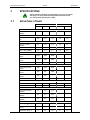
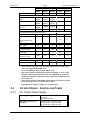
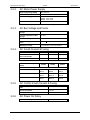
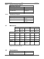
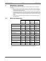
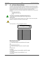
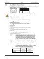
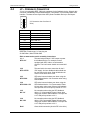
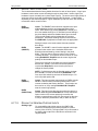
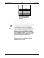
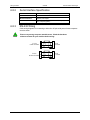
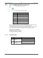
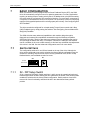
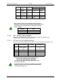
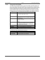
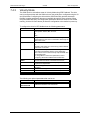
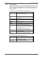
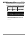
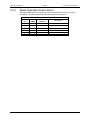
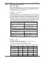
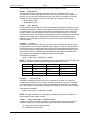
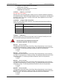
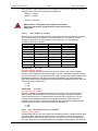
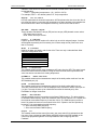
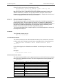
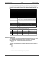
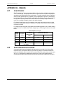
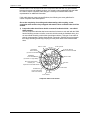
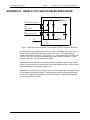
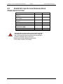
Danaher Motion Kollmorgen
03/2006
Appendix B - Cables
APPENDIX B - CABLES
B.1
LONG CABLES
The DC resistance of long motor power cables steals some of the available voltage when
motor current is high. The principal effect of this is some reduction in peak motor power so
acceleration and deceleration times can be longer. The cable resistance has no significant
effect on lower speed torque or top speed. For most applications, the loss of performance
is small with cables up to the maximum cable length specification. Do not operate an S200
DC Input Drive with long cables at the lower end of the bus voltage range because too
much of the available voltage is stolen by the cable resistance.
For S200 AC Input Drives, the DC resistance of the motor power cable is rarely an issue
because the voltage drop across the resistance is usually a small fraction of the available
nominal bus voltage.
For S200 DC Input Drives with long cables and demanding dynamics, the 14 AWG cable is
preferred over the 18 AWG cable. Cable voltage drop vs. cable length is shown in the table
below.
Cable Voltage Drop vs. Length
2 x Rphase
(ohm)
18 cable
14 cable
3
0.126
2.77
3.7 %
1.5 %
10
0.413
9.09
12.1 %
4.8 %
25
1.03
22.7
30.3 %
12.0 %
N/A
24.0 %
50
B.2
VLOSS in cable as
a percent of 75 V bus
V line-line peak
at 0.866 x 18
ARMS18 AWG
cable
Cable
Length
(meter)
(50 m not recommended with
6/18 ARMS)
CUSTOM COMPOSITE CABLES
A composite cable has both feedback and power wires in one cable. One of the critical
requirements for a composite cable is to provide a high degree of isolation between the
power and feedback wires. For 240 VAC-connected drives, the power wires can have up to
400 Vpeak-peak fast switching PWM waveforms that can couple to the feedback wiring,
causing communication errors between the Drive and the Smart Feedback Device (SFD).
S200 Reference Manual
M-SM-200-01
111