1
www.DanaherMotion.com
PicoDAD-SN Compact Dual-Axis
SynqNet Servo Drive
User Manual
Revision No: 2.0
Date: 30 January 2006
Danaher Motion Kollmorgen
January 30, 2006
Table Of Contents
1.
2.
3.
Revision History ...................................................................................................................7
Conventions...........................................................................................................................9
Product Description .............................................................................................................9
3.1
3.2
3.3
3.4
3.5
3.6
3.7
3.8
3.9
3.9.1
3.9.2
3.10
3.11
3.12
3.13
4.
Naming Conventions ..........................................................................................................13
4.1
5.
AXIS NUMBERING ............................................................................................................... 13
Drive Architecture..............................................................................................................13
5.1
5.2
5.2.1
5.2.2
5.3
5.4
6.
DRIVE PROCESSOR AND SYNQNET FPGA........................................................................... 13
FIRMWARE VERSIONS ......................................................................................................... 13
FPGA Firmware......................................................................................................... 13
DP Firmware.............................................................................................................. 13
SOFTWARE COMPATIBILITY TABLE..................................................................................... 14
DRIVE PROCESSOR MEMORY DESCRIPTIONS ...................................................................... 14
Electrical Specifications.....................................................................................................16
6.1
6.2
6.3
6.4
6.5
7.
GENERAL .............................................................................................................................. 9
SYNQNET®........................................................................................................................... 9
PART NUMBER .................................................................................................................... 10
ELECTRICAL INTERFACE ..................................................................................................... 10
CONTROL SPECIFICATIONS .................................................................................................. 10
MOTOR TYPES..................................................................................................................... 10
MOTOR FEEDBACK.............................................................................................................. 10
SECONDARY ENCODER........................................................................................................ 11
I/O ...................................................................................................................................... 11
Machine I/O................................................................................................................ 11
Controller I/O............................................................................................................. 11
POSITION CAPTURE ............................................................................................................. 12
DIAGNOSTICS ...................................................................................................................... 12
ROTARY SWITCH ................................................................................................................. 12
SERIAL COMMUNICATIONS ................................................................................................. 12
INPUT POWER ...................................................................................................................... 16
PROTECTION AND ENVIRONMENT ....................................................................................... 16
I/O ...................................................................................................................................... 17
ENCODER FEEDBACK .......................................................................................................... 18
RESOLVER ........................................................................................................................... 19
Mounting .............................................................................................................................20
7.1
HARDWARE SPECIFICATIONS .............................................................................................. 20
7.2
OUTLINE DIMENSIONS ........................................................................................................ 20
7.2.1
Front View.................................................................................................................. 21
7.2.2
Side View .................................................................................................................... 21
7.3
MOUNTING ALIGNMENT ..................................................................................................... 22
8.
Wiring..................................................................................................................................23
8.1
WIRING DIAGRAM............................................................................................................... 23
8.2
CONNECTOR PIN-OUTS ....................................................................................................... 24
8.2.1
Logic Power ............................................................................................................... 24
8.2.2
Bus Power .................................................................................................................. 24
8.2.3
Motor Power .............................................................................................................. 25
8.2.4
Feedback .................................................................................................................... 25
8.2.5
Machine I/O................................................................................................................ 26
8.2.6
Controller I/O............................................................................................................. 28
8.2.7
SynqNet....................................................................................................................... 30
8.2.8
RS-232 ........................................................................................................................ 30
8.3
WIRING A MOTOR TO THE DRIVE ........................................................................................ 31
8.3.1
Kollmorgen AKM Motors ........................................................................................... 31
PicoDAD-SN User Manual
Page 2 of 130
Danaher Motion Kollmorgen
January 30, 2006
8.4
CONNECTOR KIT ................................................................................................................. 32
8.5
GROUNDING TREE ............................................................................................................... 33
8.6
ELECTRICAL INTERFACES.................................................................................................... 33
8.6.1
Over-Travel Limits and Home.................................................................................... 33
8.6.2
Remote Enable............................................................................................................ 34
8.6.3
General-Purpose Inputs ............................................................................................. 34
8.6.4
General-Purpose Outputs........................................................................................... 34
8.6.5
High Speed Inputs ...................................................................................................... 35
8.6.6
High Speed Outputs.................................................................................................... 35
8.6.7
Analog Inputs ............................................................................................................. 35
8.6.8
Fault Relay ................................................................................................................. 36
8.6.9
Brake Relay ................................................................................................................ 36
8.6.10
Sine Encoder .............................................................................................................. 36
8.6.11
Halls ........................................................................................................................... 36
8.6.12
Quadrature Encoder................................................................................................... 36
9.
System Operation ...............................................................................................................37
9.1
9.2
9.3
9.4
9.5
9.6
9.6.1
9.6.2
9.6.3
9.6.4
9.6.5
9.7
9.7.1
9.7.2
9.7.3
9.7.4
9.8
9.8.1
9.8.2
9.8.3
9.8.4
9.8.5
9.8.6
9.8.7
9.8.8
9.8.9
9.8.10
9.8.11
9.8.12
9.8.13
9.8.14
9.9
9.9.1
9.9.2
9.9.3
9.9.4
9.10
9.10.1
9.10.2
9.10.3
POWERING UP ..................................................................................................................... 37
SYNQNET UTILITIES............................................................................................................ 37
ROTARY SWITCH CONFIGURATION ..................................................................................... 37
CURRENT SCALING ............................................................................................................. 37
PWM SATURATION ............................................................................................................. 38
DRIVE PARAMETERS ........................................................................................................... 38
Memory Operations on Drive Parameters ................................................................. 39
Accessing Individual Parameters ............................................................................... 39
Accessing an Entire Parameter Set ............................................................................ 40
Drive Parameter Map File ......................................................................................... 40
Drive Configuration File............................................................................................ 43
MOTOR POSITION ................................................................................................................ 43
Position Feedback Parameter .................................................................................... 43
Mechanical Position................................................................................................... 44
Position Resolution..................................................................................................... 44
Timing of the Position Update.................................................................................... 44
DRIVE CONFIGURATION ...................................................................................................... 44
The CONFIG Function............................................................................................... 45
Motor Parameters ...................................................................................................... 45
Feedback Parameters................................................................................................. 47
Current Loop Parameters .......................................................................................... 50
Phase Advance Parameters........................................................................................ 52
Back-EMF Compensation .......................................................................................... 53
Current Limits ............................................................................................................ 54
Application Current Limits......................................................................................... 55
Reading Actual Current.............................................................................................. 56
Current Measurement Filters ..................................................................................... 56
Current Foldback ....................................................................................................... 57
Application Velocity Limit.......................................................................................... 59
Under-Voltage Fault Processing................................................................................ 60
Motor Over-Temperature Fault Processing............................................................... 61
SETTING THE MPHASE PARAMETER .................................................................................. 62
Introduction................................................................................................................ 62
Parameter Definition.................................................................................................. 62
Calculating MPHASE using the ZERO Procedure..................................................... 62
Setting MPHASE with AKM Motors........................................................................... 63
ENCODER INDEX POSITION.................................................................................................. 63
The MENCOFF Parameter ........................................................................................ 64
MENCOFF for Kollmorgen AKM Motors.................................................................. 64
Encoder Index Initialization ....................................................................................... 64
PicoDAD-SN User Manual
Page 3 of 130
Danaher Motion Kollmorgen
9.11
9.11.1
9.11.2
9.11.3
9.12
9.12.1
9.12.2
9.12.3
9.12.4
9.12.5
9.12.6
9.13
9.13.1
9.13.2
9.13.3
9.13.4
9.13.5
9.13.6
9.13.7
9.14
9.14.1
9.14.2
9.14.3
9.15
9.16
9.16.1
9.16.2
9.16.3
9.16.4
9.16.5
9.16.6
9.16.7
9.17
9.17.1
9.17.2
9.17.3
9.18
9.18.1
9.18.2
9.18.3
9.19
9.19.1
9.19.2
9.19.3
9.19.4
9.19.5
9.20
9.21
9.21.1
10.
January 30, 2006
COMMUTATION INITIALIZATION WITH COMMUTATION SIGNALS ........................................ 66
The MFBDIR Parameter ............................................................................................ 66
For Resolver Feedback .............................................................................................. 66
For Encoder Feedback with Commutation Signals.................................................... 66
COMMUTATION INITIALIZATION WITHOUT COMMUTATION SIGNALS (PHASE FINDING) ..... 69
Overview..................................................................................................................... 69
Autonomous Drive Actions ......................................................................................... 69
Parameters Used During Phase Finding ................................................................... 70
Phase Finding and the MENCTYPE Parameter ........................................................ 71
The Process ................................................................................................................ 71
Evaluating the Commutation Initialization Process................................................... 73
CONSIDERATIONS FOR WORKING WITH ENDAT SINE ENCODERS ........................................ 73
Setting the Encoder Type............................................................................................ 73
Equivalent Counts per Revolution.............................................................................. 73
Hardware Absolute Position ...................................................................................... 73
Absolute Position Mode.............................................................................................. 74
Position Feedback Offset............................................................................................ 74
Saving Parameters in the EnDat Encoder.................................................................. 75
Sine/Cosine Calibration ............................................................................................. 75
SINE/COSINE CALIBRATION ................................................................................................ 76
Overview..................................................................................................................... 76
The Process ................................................................................................................ 76
Calibration Data ........................................................................................................ 77
DRIVE ENABLE.................................................................................................................... 79
FAULTS AND WARNINGS ..................................................................................................... 80
Warnings .................................................................................................................... 80
Faults.......................................................................................................................... 81
Reading Warnings Over SynqNet ............................................................................... 83
Reading Faults Over SynqNet .................................................................................... 83
Using the SqDriveMsg Utility .................................................................................... 84
Clearing Faults .......................................................................................................... 84
Fault History .............................................................................................................. 85
DIRECT COMMANDS ............................................................................................................ 85
Table of Direct Command Codes ............................................................................... 85
Direct Command Syntax............................................................................................. 88
Examples of Direct Commands .................................................................................. 88
REAL TIME MONITORING .................................................................................................... 88
Values Available for Real-Time Monitoring............................................................... 89
Setting up Real-Time Monitoring ............................................................................... 89
Viewing Monitored Data on MotionScope ................................................................. 90
ANALOG INPUTS.................................................................................................................. 92
Reading Analog Inputs using Drive Parameters ........................................................ 93
Accessing Analog Inputs Using Direct Commands .................................................... 93
Analog Value Monitoring ........................................................................................... 94
Zeroing the Analog Input Offset ................................................................................. 94
Low-pass Filtering on the Analog Inputs ................................................................... 94
SYNQNET CYCLIC STATUS BITS ......................................................................................... 95
POSITION CAPTURE ............................................................................................................. 96
Controller Time-Based Position Capture................................................................... 96
Firmware Upgrade Procedure ..........................................................................................96
10.1
IDENTIFYING THE FIRMWARE FILES .................................................................................... 97
10.2
PREPARATIONS .................................................................................................................... 97
10.2.1
Retrieve Drive Parameters ......................................................................................... 97
10.2.2
Clear the Drive Parameters ....................................................................................... 98
10.3
UPDATE DRIVE FIRMWARE ................................................................................................. 99
10.3.1
Using MotionConsole................................................................................................. 99
PicoDAD-SN User Manual
Page 4 of 130
Danaher Motion Kollmorgen
January 30, 2006
10.3.2
Using the sqNodeFlash Utility ................................................................................. 101
10.4
RESUMING OPERATION ..................................................................................................... 102
10.4.1
Verify the VERSION ................................................................................................. 102
10.4.2
Restore Drive Parameters ........................................................................................ 102
11.
Trouble Shooting ..............................................................................................................104
11.1
11.1.1
11.1.2
11.2
11.3
11.4
11.4.1
11.4.2
11.4.3
11.5
11.6
12.
13.
Appendix: SynqNet Utilities ............................................................................................113
Appendix: Application Programming Considerations .................................................114
13.1
13.2
13.3
14.
15.
16.
FPGA RUN-TIME IMAGE ................................................................................................... 114
MOTOR POSITION .............................................................................................................. 114
DRIVE PARAMETERS ......................................................................................................... 114
Appendix: Sample Drive Parameter Map File ..............................................................115
Appendix: Sample Drive Configuration File .................................................................118
Appendix: Reference Guide ............................................................................................119
16.1
16.2
16.3
17.
SYNQNET LEDS................................................................................................................ 104
IN Port...................................................................................................................... 105
OUT Port.................................................................................................................. 105
DRIVE STATUS 7-SEGMENT LED ...................................................................................... 105
RETRIEVING FAULT INFORMATION OVER SYNQNET ......................................................... 107
FAULT R-8: A/B OUT-OF RANGE ...................................................................................... 108
Background .............................................................................................................. 108
Viewing the Sine and Cosine Signals ....................................................................... 109
Adjusting the Allowed Range.................................................................................... 109
IDENTIFYING FIRMWARE VERSIONS .................................................................................. 110
DRIVE ERROR RESPONSE .................................................................................................. 111
INSTRUCTIONS .................................................................................................................. 119
PARAMETERS .................................................................................................................... 119
EFFECT OF RSTVAR AND CLREEPROM ........................................................................ 123
Appendix: Upgrading Firmware over the Serial Port ..................................................125
17.1
17.2
17.3
17.3.1
17.3.2
17.4
17.4.1
17.4.2
17.4.3
17.5
17.5.1
17.5.2
17.6
TERMINOLOGY .................................................................................................................. 125
IMPORTANT FILES ............................................................................................................. 125
PREPARATIONS .................................................................................................................. 125
Retrieve Drive Parameters ....................................................................................... 125
Clear the Drive Parameters ..................................................................................... 126
UPDATE DRIVE FIRMWARE ............................................................................................... 127
Communications Settings ......................................................................................... 127
Select Files ............................................................................................................... 128
Start Firmware Update ............................................................................................ 129
RESUMING OPERATION ..................................................................................................... 129
Return Drive to Operational State............................................................................ 129
Restore Drive Parameters ........................................................................................ 129
CONSIDERATIONS FOR HARDWARE EMBER ....................................................................... 129
Table of Figures
Figure 5-1: Drive Memory Architecture........................................................................................................ 15
Figure 9-1: Current Scaling ...................................................................................................................... 38
Figure 9-2: Current Foldback....................................................................................................................... 58
Figure 9-3: Commutation Initialization Velocity Response .......................................................................... 73
Figure 9-4: Warning indication in MotionConsole........................................................................................ 81
Figure 9-5: VM3 Screen Showing Monitored Data...................................................................................... 90
Figure 9-6: Selecting Traces in MotionScope ............................................................................................. 91
PicoDAD-SN User Manual
Page 5 of 130
Danaher Motion Kollmorgen
January 30, 2006
Figure 9-7: Defining New Traces in MotionScope....................................................................................... 92
Figure 10-1: SqNode Summary Window for Firmware Download .............................................................. 99
Figure 17-1: MotionLink Main Screen........................................................................................................ 125
Figure 17-2: MotionLink Drive Backup Screen.......................................................................................... 126
Figure 17-3: Ignite28xx Main Screen......................................................................................................... 127
PicoDAD-SN User Manual
Page 6 of 130
Danaher Motion Kollmorgen
January 30, 2006
1. Revision History
Revision
Number
Date
1.0
1.1
December 22, 2004
1.3
1.4
January 18, 2005
1.5
June 10, 2005
1.6
July 22, 2005
1.7
August 30, 2005
1.8
September 21, 2005
Description
•
•
•
•
•
•
•
•
•
•
•
•
•
•
•
•
•
•
•
•
•
•
•
•
•
•
•
•
•
•
•
•
•
•
•
•
•
•
•
•
•
•
1.9
December 5, 2005
•
•
•
•
•
•
•
•
•
•
•
PicoDAD-SN User Manual
First official version
Added clarification on Rotary Switch
Mounting: book or brick
SN Connector: RJ-45
Added info on velocity limit
Added info on under-voltage and motor over-temp processing
Added clarification regarding position capture
Added sine encoder input frequency limit
Corrections to mating connector part numbers
Corrections to pin-out of Controller I/O
Clarification of Current Scaling
Clarification of Mounting
Added information on Position Capture (both Controller- and DriveBased)
Added information on Commutation Initialization without Halls
Added Warning register information
Added information on the Connector Kit
Added info on PWM saturation
Real-time monitoring: clarification on how to find the monitor data
Added information on current foldback
Added information on drive parameter Map files
Added information on downloading firmware using sqNodeFlash
Added information on 1.5V reference failure
Corrections to syntax for reading analog inputs using Direct Command
0x30
Added information on the VLIM parameter
Added information on EnDat
Added information on sine/cosine calibration
Added information on firmware upgrade using the serial port
Clarification to DIPEAK and DICONT
The PicoDAD will NOT run brush DC motors
Added description of UVTIME for UVMODE=2
Added description for ABSPOSMOD
Added description for PFBOFF
Added clarification on Current Scaling
Added information on configuring the drive (CONFIG)
Added information on using MOTORTYPE=3 with AKM motors
Added descriptions of MPHASE and MENCOFF
Added current measurement filters
Calculating MPHASE with the ZERO function
Phase finding
Added information on the RS-232 port, and on Hardware Ember
Added description of the flashing ‘-‘ & ‘3’ LED indication. Refer to Drive
Status 7-segment LED information.
Removed information on drive-controlled position capture (not
supported)
Added wiring diagram information
Added clarifications to the Phase Finding description
Removed MPHASE calculation for AKM motors. When using AKM,
always set MOTORTYPE=3.
Clarification regarding setting MENCOFF for AKM motors.
Corrected range for MSININT, MKT, MJ, MICONT, MOTORTYPE,
FOLDMODE
Added descriptions for analog input zeroing, offset, and low-pass filtering
Removed irrelevant parameters from the reference
Clarification added for requiring CONFIG when changing parameters
Added descriptions for READY and ACTIVE
Added descriptions for zeroing the analog input offset.
Added descriptions of the analog input low-pass filter
Page 7 of 130
Danaher Motion Kollmorgen
2.0
PicoDAD-SN User Manual
January 30, 2006
• Added descriptions for changing the allowed range of sine/cosine inputs
• Clarifications to Product Description.
• Removed reference to linear motors. The PicoDAD will only work with
rotary brushless motors. Refer to the MOTORTYPE parameter.
• Clarification regarding supported feedback types
Page 8 of 130
Danaher Motion Kollmorgen
January 30, 2006
2. Conventions
Warning identifies hazards that could result in personal injury or death.
Caution identifies hazards that could result in personal injury or equipment
damage.
Note identifies information critical to the user’s understanding or use of the
equipment.
3. Product Description
3.1
General
The PicoDAD-SN is a low-voltage Dual-Axis SynqNet® Drive. Incorporating two independent servo drives,
this product saves space on a machine, and lowers the system cost by utilizing shared components. The
PicoDAD operates on 48VDC for the Bus power, and separate 24VDC for Logic power. Separation of Bus
and Logic power allows bus power control to be incorporated into the machine safety chain, while not
losing application information or real-time monitoring data during E-stop events. Each axis is capable of
individually sourcing 10A RMS continuous current to the motor. One version of the drive offers 10A RMS
peak current per axis, and the other option offers 20A RMS peak current.
The PicoDAD-SN is designed as a torque drive, while servo control is executed by the centralized motion
controller. Compensation of the drive for use with a specific motor is achieved by programming a set of
parameters that reflect the physical characteristics of the electro-mechanical system. Real-time data
monitoring allows for on-line diagnostics and preventative maintenance. Extensive I/O support is provided,
including dedicated Home, Over-travel limits, brake control, and general-purpose opto-isolated and highspeed I/Os. Machine-oriented I/O is separate from Controller-oriented I/O, for ease of cabling.
In addition to status information being accessible via SynqNet®, 7-segment LEDs provide a clear drive
status display, individually for each axis. All drive capabilities are accessible over SynqNet, including
firmware download.
3.2
SynqNet®
SynqNet (http://www.synqnet.org/) is an all-digital motion control interface for connections between
controllers and drives. The physical layer of SynqNet is based on IEEE 802.3 standards for 100Base-TX,
the physical layer of Ethernet. The data link and application layers of SynqNet are specifically designed for
motion control applications. The 100BASE-TX media system is based on specifications published in the
ANSI TP-PMD physical media standard. The 100BASE-TX system operates over two pairs of wires, one
pair for 'receive' data signals and the other pair for 'transmit' data signals.
SynqNet replaces the noise-prone analog drive-motion controller interface (±10V + Encoder) with a realtime digital network that brings additional diagnostic, performance and reliability benefits to a machine.
PicoDAD-SN User Manual
Page 9 of 130
Danaher Motion Kollmorgen
3.3
January 30, 2006
Part Number
PDD 04 xx 165
where
•
3.4
xx refers to the current level that the drive can source.
o
10: 10 Amps RMS continuous and 10 Amps RMS peak
o
20: 10 Amps RMS continuous and 20 Amps RMS peak
Electrical Interface
•
Bus Voltage
48VDC
•
Logic Power
24VDC
•
Motor Power
10A RMS continuous, with either 10A RMS or 20A RMS peak per axis
For more details, please refer to the Electrical Specification.
3.5
Control Specifications
•
Current loop closure rate: 62.5msec (16kHz)
•
PWM Frequency: 16kHz
3.6
Motor Types
The drive will work with rotary brushless motors.
3.7
Motor Feedback
Encoder, Resolver and Sine Encoder feedback options are supported as standard. All options are
supported in a single model number; and the feedback type is set by a drive parameter.
The following table describes which feedback configurations are supported, and in which firmware
versions.
Firmware Version
Feedback Types Supported
0.1.9
Incremental Encoder
•
A/B plus Halls (MENCTYPE=6)
•
A/B/I plus Halls (MENCTYPE=0)
• A/B only (MENCTYPE=4)
Resolver
PicoDAD-SN User Manual
Page 10 of 130
Danaher Motion Kollmorgen
January 30, 2006
Firmware Version
Feedback Types Supported
1.0.0.0
Incremental Encoder
•
A/B/I plus Halls (MENCTYPE=0)
•
A/B only with explicit initialization (MENCTYPE=3). Refer to Phase
Finding.
•
A/B only (MENCTYPE=4)
• A/B plus Halls (MENCTYPE=6)
Sine Encoder
•
A/B only with explicit initialization (MENCTYPE=3). Refer to Phase
Finding.
•
A/B only (MENCTYPE=4)
• EnDat (MENCTYPE=9)
Resolver
For more details, please refer to the sections on Feedback Devices and Configuring Motor Feedback.
3.8
Secondary Encoder
Secondary feedback is supported on both axes, and accommodates a differential A/B quadrature encoder
signal. An Index signal is supported on axis 2 only. The drive provides 5V power individually to each of the
secondary encoders.
The Secondary Feedback inputs are located on the Machine I/O connector.
3.9
I/O
The I/O is divided into two general categories, Machine I/O and Controller I/O. There are two
corresponding I/O connectors on the drive. The I/O electrical interfaces are described in the Electrical
Interfaces section.
3.9.1 Machine I/O
The following I/O points exist for each axis independently:
•
Home
•
Positive and negative over-travel limits
•
Brake control. The brake relays are driven by the “Brake Apply” output of the SynqNet FPGA.
Each relay is rated to 24VDC and can carry up to 1A.
These signals are routed to and controlled by the SynqNet FPGA, and are thus processed at the controller
level only.
3.9.2 Controller I/O
•
8 general purpose opto-isolated inputs
•
4 general purpose opto-isolated outputs
•
Enable. Each axis has its own Remote Enable input. By default, the remote enable input has to be
asserted in order to enable the drive, but this requirement may be ignored by using the
RMTMODE drive parameter.
•
High-speed I/O
o Four RS-422 inputs. These may be used for position capture.
o Six RS-422 outputs
PicoDAD-SN User Manual
Page 11 of 130
Danaher Motion Kollmorgen
•
January 30, 2006
4 general-purpose analog inputs
o +/- 10Vdc
o 12-bit resolution
•
Dry-contact fault relay. There is one fault relay, driven by the “Node Alarm” output of the SynqNet
FPGA.
All General Purpose Digital I/O signals are wired directly to the SynqNet FPGA, and are thus processed at
the controller level only. The analog inputs are processed by the DSP, and available for reading over
either the service channel or via Real-Time Monitoring.
3.10
Position Capture
The following inputs are available for use as triggers for Position Capture:
•
All 8 general purpose opto-isolated inputs.
•
All 4 RS-422 inputs.
•
The Home input on both axes
•
The over-travel limits on both axes.
The user should be aware that opto-isolated inputs have an inherent delay in the order of tens of
microseconds.
3.11
Diagnostics
•
7-Segment LED shows axis status and fault codes. Please refer to Drive Status 7-Segment LED
for more details.
•
SynqNet LEDs provide information on the SynqNet connection. Refer to the section on SynqNet
LEDs for more details.
•
Real-time indication of a warning or a fault is communicated over the cyclic status bits
•
The fault status word contains information on each existing fault, and can be read by the motion
controller.
•
Internal analog input for measurement of Bus voltage and of Drive temperature
•
Real-time data monitoring for the following values:
o
o
o
o
3.12
Bus voltage
Drive temperature
Analog inputs
Phase currents and overall torque
Rotary Switch
The PicoDAD is equipped with a 16-pole rotary switch. The switch is connected to the SynqNet FPGA and
its use is application-specific. The switch is mounted on the top of the drive. For more information, refer to
the section on rotary switch configuration.
3.13
Serial Communications
Serial communications over RS-232 is supported, primarily for debugging purposes. It is possible to set
parameters and to download firmware over this port. However, in the interests of system simplicity, it is
best to use one communications channel, viz. SynqNet, for these operations.
PicoDAD-SN User Manual
Page 12 of 130
Danaher Motion Kollmorgen
January 30, 2006
4. Naming Conventions
4.1
Axis Numbering
The axes on the drive are labeled Axis 1 and Axis 2. This convention is used when describing connector
pin-outs.
From a software point of view, the axes are identified over SynqNet as being Axes 0 and 1 respectively.
5. Drive Architecture
5.1
Drive Processor and SynqNet FPGA
The PicoDAD consists of two primary components, these being a Drive Processor (DP), coupled with a
SynqNet FPGA. The DP performs the current loop and commutation functions, while the FPGA
implements the SynqNet and I/O interface. DP is held in a reset state by the SynqNet FPGA, and is
released from this state only upon execution of a SynqNet RESET.
Note: After power up, and before the SynqNet RESET is executed, only the
decimal point on the drive LED will be lit
5.2
Firmware Versions
Both the DP and the FPGA have a firmware associated with them. These files are independent of each
other, and provide different aspects of the drive’s functionality. By executing the VERSION SynqNet utility,
one can get information on the versions of all these entities. The VERSION utility is typically executed
from within a DOS window, and run from the *\XMP\BIN\WinNT directory.
5.2.1 FPGA Firmware
The FPGA provide the SynqNet and the I/O functionality. It has two FPGA images, one called a BOOT
image and the other called a RUNTIME image. A valid run-time image is needed for the drive to be
operational, and the run-time image version must be compatible with the version of the MPI.
Each MPI installation includes the run-time files for each drive partner. The PicoDAD FPGA is identified by
the prefix C0FE0035_xyzw, while the 4-digit suffix (xyzw) identifies the version of the run-time image.
When starting up MoCon, a message will be displayed if the run-time version of the FPGA is not
compatible with the MPI, and an interface provided for download the correct version (refer to section on
Firmware Upgrade Procedure). The correct version is found in the XMP\BIN sub-directory of the software
installation, in a *.sff file.
Note: The PicoDAD is shipped from the factory with the FPGA run-time image
cleared. This is done because customers may have different versions of the MPI,
and each version may require a different version of the run-time image. Application
programs should check the version at system initialization, and download the
correct run-time image if necessary. In general, this will be done once for each
drive, as the image is stored in non-volatile memory.
5.2.2
DP Firmware
The DP firmware provides the current loop and other drive configuration functionality. It is updated as the
need arises in order to support new features. It is not necessarily related to a specific version of MPI or
FPGA run-time image. The firmware file is identified by a file name having the following general format:
PicoDAD-SN User Manual
Page 13 of 130
Danaher Motion Kollmorgen
January 30, 2006
pDad_xyz.i00
where xyz represents the firmware version. For example, ‘013’ is firmware version 0.1.3.
5.3
Software Compatibility Table
There are at least three elements of software/firmware in the SynqNet system:
•
Motion controller software (called the MPI)
•
FPGA run-time image
•
Drive Processor firmware
The following table shows compatible sets of these software entities.
MPI
FPGA
Drive Processor
03.02.00
C0FE0035_0343.sff
0.1.6
03.02.00
C0FE0035_0343.sff
0.1.9
5.4
Drive Processor Memory Descriptions
The drive contains a number of different memory types:
Flash Memory: used to store the drive firmware
RAM: used to store drive parameters during run-time
DSP EEPROM: non-volatile memory used to store drive parameters even when the power is off
At power up, the drive will attempt to load parameter values from the EEPROM into the RAM. A checksum
of these parameter values is kept, and this is verified when the EEPROM contents are loaded. If the
checksum is invalid, default values for drive parameters are loaded into RAM. These default values are
hard-coded, and are as such part of the firmware file.
When parameter values are set, these values are stored in RAM, and will be lost when power is removed
form the drive. Once a working set of drive parameters has been found, the parameters can be stored in
non-volatile EEPROM memory. This is done using either the serial SAVE command, or the SynqNet 0x1C
Direct Command.
Changes made to parameter values are stored in RAM. It is possible to revert to a saved configuration by
explicitly loading the parameters from the EEPROM. This is done using either the serial LOAD command,
or the SynqNet 0x1E Direct Command.
The default parameter values can be loaded into RAM by executing either the serial RSTVAR command,
or the SynqNet 0x1D Direct Command.
The EEPROM may be cleared using either the serial CLREEPROM command, or the SynqNet 0x1F
Direct Command.
PicoDAD-SN User Manual
Page 14 of 130
Danaher Motion Kollmorgen
January 30, 2006
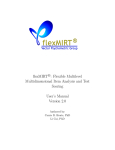
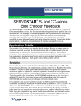
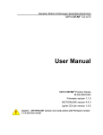
The following diagram illustrates the relationship between the different types of memory.
SAVE
RSTVAR
Flash
Stores Firmware and
default parameter values
RAM
Stores run-time
parameter values
CLREEPROM
EEPROM
Non-volatile memory for
parameter values
LOAD
CLREEPROM loads default values into RAM
and clears non-volatile memory
Figure 5-1: Drive Memory Architecture
PicoDAD-SN User Manual
Page 15 of 130
Danaher Motion Kollmorgen
January 30, 2006
6. Electrical Specifications
6.1
Input Power
10A
Drive Model
Main Input Power
(both axes)
Voltage (DC) Nominal ± 10%
20A
48VDC
KVA
Continuous current (Amps)
Peak Current (Amps) for 500 msec
Peak Current (Amps) for 2 sec
Line fuses
Rated Output Power
(Per Axis)
Logic Power
Continuous Power (VA) at 48VDC Input and
45°C (113°F) Ambient
0.35
Continuous Current (Arms)
10A for each
axis
10A for each
axis
Peak Current (Arms) for 500 mSec
10A for each
axis
20A for each
axis
Peak Current (Arms) for 2 Sec
10A for each
axis
TBD
PWM Frequency (kHz) PWM
16
Motor Current Ripple (kHz)
32
PWM Saturation
92.5% 1
+24 VDC Ext. Logic Voltage (volts)
22 to 27
+24 VDC Ext. Logic Current (amps sink)
+24 VDC Ext. Logic Current (amps max inrush)
6.2
2A for 5msec, and then 1.5A
for 7msec
Protection and Environment
Protective Functions
Under Voltage trip
User programmable from 12 to 36VDC
Over Voltage Trip
60VDC (FW versions up to and including 0.1.9)
70VDC (FW versions above 0.1.9)
Environment
Over Temperature Trip
80° C / 176° F
Operating Temperature
5°C (41°F) to 45°C (113°F)
Storage Temperature
0°C (32°F) to 70°C (158°F)
Ambient Humidity
10% to 90%
1
PWM saturation affects the useable bus voltage. With a 48V input and with PWM saturation set to
92.5%, the effective bus voltage is 44.4V. This affects the maximum achievable speed.
PicoDAD-SN User Manual
Page 16 of 130
Danaher Motion Kollmorgen
6.3
January 30, 2006
I/O
Analog Inputs
Maximum Voltage
±12.5 V differential
Operating Voltage Range
±10 V differential
Input Resolution
12 bit
Sensitivity
6.1mV 2
Input Impedance/CMR
> 10 K ohms/50 dB
Frequency Response
LPF at 3.8Khz
Accuracy
Repeatability
Bus Voltage Measurement
Filtering
LPF at 3Hz
Drive Temperature Measurement
Filtering
LPF at 1.5kHz
General Purpose Digital Inputs
Input circuit characteristic
Opto-coupler
Input voltage
5-24Vdc
Maximum current
10mA per input
Over-Travel and Home
Remote Enable
Delay
Output circuit characteristic
Opto-coupler; open
collector, common
emitter, Sink
configuration
Maximum load capacity
24Vdc / 60mA
Maximum saturated voltage
2V
Input Signal Characteristic
RS422
Maximum frequency
2.5MHz
Output format
RS422
Maximum frequency
2.5MHz
General Purpose Digital Outputs
Fast Inputs
Fast Outputs
2
25V(full span)/4096 (12 bit)
PicoDAD-SN User Manual
Page 17 of 130
Danaher Motion Kollmorgen
6.4
January 30, 2006
Encoder Feedback
Encoder power
supply
Quadrature Encoder
Encoder supply Voltage
5VDC
Encoder supply current
300mA for each encoder interface
Signal Characteristics
A/B
Differential RS422
Index
Differential RS422
Halls
Differential, single-ended or opencollector
Maximum quadrature input frequency
Sine Encoder
3MHz (before quadrature)
Signal Characteristics
A/B
Differential, 1Vp-p @ 2.5V offset
Index
Differential 1Vp-p or RS422
Halls
Differential, single-ended or opencollector
EnDat
RS422 data + clock
Maximum sine encoder input
frequency
-3dB at 265kHz
Interpolation
Set by a drive parameter (MSININT)
Maximum value is x512 before
quadrature.
Equivalent resolution in counts per rev
is
MENCRES * MSININT * 4
Note: The quadrature encoder must have differential RS-422 A, B, Z signals. The
PicoDAD will not work with single-ended TTL feedback signals.
PicoDAD-SN User Manual
Page 18 of 130
Danaher Motion Kollmorgen
6.5
January 30, 2006
Resolver
The PicoDAD can use single-speed (two-pole) resolver feedback to monitor the motor shaft position. A
resolver can be thought of as a transformer whose output is unique for any given shaft position (an
absolute position feedback). The transformer is driven with a sine wave reference signal. Two AC signals
are returned from the resolver into the Sine and Cosine inputs.
Type
Single-pole
Transformation Ratio
0.4 to 0.6 (dependant on the Resolver itself)
Modulation Frequency
8kHz
Input Voltage (From Drive)
Max DC Resistance
Max Drive Current
Output Voltage (To Drive)
Accuracy
ResBW = 300
TBD ArcMin
ResBW = 600
TBD ArcMin
ResBW = 300
TBD ArcMin
ResBW = 600
TBD ArcMin
Repeatability
PicoDAD-SN User Manual
Page 19 of 130
Danaher Motion Kollmorgen
January 30, 2006
7. Mounting
The PicoDAD-SN is designed for book mounting. This panel assembly is then mounted in a metallic
enclosure. Enclosures are supplied by the manufacturers of the final product and meet the environmental
IP rating of the end product. To ensure proper grounding (and to optimize EMC), the enclosure should
have continuous ground continuity maintained between all metal panels. This ground continuity is intended
to be both a safety ground and a high frequency ground.
The units are mounted on a backplane installed into the enclosure. Ideally, the backplane should be an
unpainted metallic surface to optimize electrical bonding of the frame and provide the lowest possible
impedance path to earth ground. These enclosures also provide added safety.
Particular care should be used when layout of an enclosure is designed. Separate power wires from small
signal wires. The following guidelines highlight some important wiring practices to implement:
•
Control and signal cables must be separated from power and motor cables. Distance of 20 cm (8
in.) is sufficient in most cases.
•
Control and signal cables must be shielded to reduce the effects of radiated interference.
•
When control cables must cross power or motor cables, they should cross at an angle of 90°, if
possible. This reduces the field coupling effect
7.1
Hardware Specifications
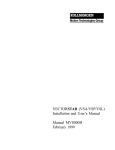
7.2
Outline Dimensions
163.2 (Height) x 71.5 (Width) x 116.3 (Depth) mm. (6.44” x 2.81” x 4.58”)
The Height dimensions specified here do not include the mounting flange.
PicoDAD-SN User Manual
Page 20 of 130
Danaher Motion Kollmorgen
January 30, 2006
7.2.1 Front View
7.2.2 Side View
PicoDAD-SN User Manual
Page 21 of 130
Danaher Motion Kollmorgen
7.3
January 30, 2006
Mounting Alignment
The drive must be vertically mounted, to allow for convection cooling.
At least 1cm of space must be left between adjacent drives
PicoDAD-SN User Manual
Page 22 of 130
Danaher Motion Kollmorgen
January 30, 2006
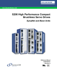
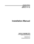
8. Wiring
Wiring Diagram
Phase B
M
13
4
14
5
15
6
16
7
17
8
18
9
19
10
20
1
11
2
12
3
13
4
14
5
15
6
16
7
17
8
18
9
19
10
20
Motor 1
Chassis
Phase C
12
Phase A
14
15
1
2
Axis 2 Common
Axis 2 CW
Axis 2 Home
Axis 2 CCW
+
l
2
48 V IN
48 V RTN
SynqNet RJ-45
-
Bus In (48V)
Bus IN (48 V)
+
26
27
1
2
Secondary Encoder #2
RS-422
I
Power
supply
(5-24V)
Power
supply
(5-24V)
In Common 1
In 1
In 2
In 3
In 4
In Common 2
In 5
In 6
In 7
In 8
Out Common
Out 1
Load
Out 2
Load
Out 3
Load
Out 4
Load
Brake Relay
Power
supply
(5 - 24V)
Power
supply
(5 - 24V)
+
Power
supply
(5 -24V)
Fault Relay
In Common 3
Axis 1 Enable
Axis 2 Enable
Power
supply
(5 - 24V)
Fast Out #1
Fast Out #2
Fast Out #3
Fast Out #4
Fast Out #5
Fast Out #6
Fast Outputs
RS - 422
Fast In #2
Fast Inputs
RS - 422
Fast In #4
Analog Inputs
24 V
+
24V In
PE
PicoDAD-SN User Manual
B
Brake Relay x 2
Fast In #3
Power
supply
48V
Secondary Encoder #1
RS-422
B
5V
Axis 1 Common
Axis 1 CW
Axis 1 CCW
Axis 1 Home
Fast In #1
1
A
24VDC
M1 Feedback
Phase A
2
3
A
5V
Page 23 of 130
-
Power
supply
24V
NOTE: Refer to the Control I/O
Connector pin-out for pin
numbers
Phase B
M
11
Machine I/O
M0 Feedback
Motor 0
Chassis
Phase C
1
NOTE: Refer to the Macine I/O
Connector pin-out for pin
numbers
8 8
Pico DAD
Control I/O
8.1
Danaher Motion Kollmorgen
8.2
January 30, 2006
Connector Pin-Outs
8.2.1 Logic Power
Connector Definition
Manufacturer
Phoenix Contact
Part Number
MSTB 2,5/2-GF-5,08
Mating Connector Part Number
MSTBT 2,5/ 2-STF-5,08
Pin Out
Pin #
Description
1
Logic Power
2
Logic Power return
Comments
Refer to Grounding Tree
8.2.2 Bus Power
Connector Definition
Manufacturer
Molex
Part Number
42820-2212
Mating Connector Part Number
42816-0212 (Housing)
42815-0011 (Pins)
63813-0500 (Manual Extraction Tool)
Pin Out
Pin #
Description
1
Bus Power
2
Bus Power return
PicoDAD-SN User Manual
Comments
Refer to Grounding Tree
Page 24 of 130
Danaher Motion Kollmorgen
January 30, 2006
8.2.3 Motor Power
Connector Definition
Manufacturer
Molex
Part Number
43160-3104
Mating Connector Part Number
44441-2004 (Housing)
43375-0001 (Pins)
63813-0500 (Manual Extraction Tool)
Pin Out
Pin #
Description
Comments
1
Chassis
Refer to Grounding Tree
2
Phase C
3
Phase B
4
Phase A
8.2.4 Feedback
8.2.4.1
Connector Definition
Manufacturer
Part Number
Mating Connector Part Number
8.2.4.2
Connectors from any of the following manufacturers
are used: 3M; ACON; Hirose
3M
N10220-52B2VC
ACON HBR20-20K3211
Hirose DX106GM-20SE
3M
Connector:
10120-6000EC
Housing:
10320-3210-00
Cable:
3M 3444C-10P
Connector Pin Arrangement
Pin #2
Pin #1
Pin #20
PicoDAD-SN User Manual
Pin#11
Page 25 of 130
Danaher Motion Kollmorgen
8.2.4.3
Pin #
1
2
3
4
5
6
7
8
9
10
11
12
13
14
15
16
17
18
19
20
January 30, 2006
Pin Out
Incremental
Encoder
E5V
E5V
A
A\
Z
Z\
Hall1
Hall1\
Hall3
Hall3\
DGND
DGND
B
B\
DGND
DGND
Hall2
Hall2\
Motor temp
Motor temp rtn
Resolver
E5V
E5V
Sine
Sine\
Ref
Ref\
DGND
DGND
Cosine
Cosine\
DGND
DGND
Motor temp
Motor temp rtn
Sine Encoder
EnDat
E5V
E5V
A
A\
Sine Encoder
C/D
E5V
E5V
A
A\
SSI Data
SSI Data\
C
C\
DGND
DGND
B
B\
DGND
DGND
SSI Clock
SSI Clock\
Motor temp
Motor temp rtn
DGND
DGND
B
B\
DGND
DGND
D
D\
Motor temp
Motor temp rtn
8.2.5 Machine I/O
8.2.5.1
Connector Definition
Manufacturer
Part Number
Mating Connector Part Number
PicoDAD-SN User Manual
Connectors from any of the following manufacturers are
used:
3M; ACON; Hirose
3M
N10226-52B2VC
ACON HBR26-20K3211
Hirose DX106GM-26SE
3M
Connector:
10126-6000EC
Housing:
10326-3210-00
Cable:
3M 3444C-13P
Page 26 of 130
Danaher Motion Kollmorgen
8.2.5.2
January 30, 2006
Connector Pin Arrangement
Pin #2
Pin #1
Pin #26
8.2.5.3
Pin #
1
2
Pin #14
Pin Out
Description
Common for Axis 1 inputs
Axis 1 negative limit
3
4
5
6
7
Axis 1 secondary encoder B signal
Axis 1 secondary encoder B-complement signal
Axis 1 secondary encoder A signal
Axis 1 secondary encoder A-complement signal
Axis 2 positive limit
8
Axis 2 home signal
9
Axis 2 negative limit
10
11
12
13
14
Axis 2 secondary encoder Index signal
Axis 2 secondary encoder Index-complement
signal
Axis 2 brake+ contact
Axis 2 brake- contact
Axis 1 positive limit
15
16
5VDC supply to secondary encoder
Axis 1 home signal
17
Ground for secondary encoder power
PicoDAD-SN User Manual
Comments
Common for CW, CCW and Home
Opto input; 5-24V; Wired to SynqNet FPGA
Referenced to Common on pin #1
RS-422 input
RS-422 input
Opto input; 5-24V; Wired to SynqNet FPGA
Referenced to Common on pin #20
Opto input; 5-24V; Wired to SynqNet FPGA
Referenced to Common on pin #20
Opto input; 5-24V; Wired to SynqNet FPGA
Referenced to Common on pin #20
RS-422 input; wired to SynqNet FPGA
Dry contact relay; controlled by SynqNet FPGA.
Note polarization
Opto input; 5-24V; Wired to SynqNet FPGA
Referenced to Common on pin #1
Fuse-protected; resettable fuse
Opto input; 5-24V; Wired to SynqNet FPGA
Referenced to Common on pin #1
Connected to Digital Ground in the drive
Page 27 of 130
Danaher Motion Kollmorgen
Pin #
18
19
20
21
22
23
24
25
26
January 30, 2006
Description
Axis 1 brake+ contact
Axis 1 brake- contact
Common for Axis 2 inputs
Axis 2 secondary encoder B-complement signal
Axis 2 secondary encoder B signal
Ground for secondary encoder power
Axis 2 secondary encoder A-complement signal
5VDC supply to secondary encoder
Axis 2 secondary encoder A signal
Comments
Dry contact relay; controlled by SynqNet FPGA.
Note polarization
Common for CW, CCW and Home
RS-422 input; wired to SynqNet FPGA
Connected to Digital Ground in the drive
RS-422 input (with pin 26); wired to SynqNet
FPGA
Fuse-protected; resettable fuse
RS-422 input (with pin 24); wired to SynqNet
FPGA
8.2.6 Controller I/O
8.2.6.1
Connector Definition
Manufacturer
Connectors from any of the following
manufacturers are used:
3M; ACON; Hirose
3M
N10250-52B2VC
ACON HBR50-20K3211
Hirose DX106GM-50SE
3M
Connector
10150-6000EC
Housing
10350-A200-00
Cable:
3M 3444C-25P
Part Number
Mating Connector Part Number
8.2.6.2
Connector Pin Arrangement
Pin #2
Pin #1
Pin #50
8.2.6.3
Pin #
1
2
3
Pin #26
Pin Out
Description
Common for Opto-isolated Inputs 1, 2, 3, 4
Motor 0, OPTO IN2
Motor 0, OPTO IN1
PicoDAD-SN User Manual
Comments
Referenced to Common on pin #1
Referenced to Common on pin #1
Page 28 of 130
Danaher Motion Kollmorgen
Pin #
4
5
6
7
8
9
10
11
12
13
14
15
16
17
18
19
20
January 30, 2006
Description
Motor 1, OPTO IN2
Motor 1, OPTO IN1
Motor 1, REMOTE ENABLE
Motor 0, REMOTE ENABLE
Common for Opto-isolated Outputs 1, 2, 3, 4
Motor 1, OPTO OUT1
Motor 1, OPTO OUT0
Motor 0, RS422 OUT3
Motor 0, RS422 OUT3 Complement
Motor 0, RS422 OUT2
Motor 0, RS422 OUT2 Complement
Motor 1, RS422 OUT1 Complement
Motor 1, RS422 OUT1
Motor 0, RS422 IN2
Motor 0, RS422 IN2 Complement
Motor 0, RS422 IN1
Motor 0, RS422 IN1 Complement
Comments
Referenced to Common on pin #30
Referenced to Common on pin #30
Referenced to Common on pin #33
Referenced to Common on pin #33
Referenced to Common on pin #8
Referenced to Common on pin #8
RS-422 output; wired to SynqNet FPGA
RS-422 output; wired to SynqNet FPGA
RS-422 output; wired to SynqNet FPGA
RS-422 input; wired to SynqNet FPGA
RS-422 input; wired to SynqNet FPGA
Reference ground for Axis 1 analog inputs. This
pin should be connected to the ground of the
analog command source.
Reference ground for Axis 2 analog inputs. This
pin should be connected to the ground of the
analog command source.
21
Analog Ground
22
Analog Ground
23
24
Axis 1 Analog Input #2
Axis 1 Analog Input #2 Complement
Differential analog Input; ±10Vdc
25
Axis 2 Analog Input #2
Differential analog Input; ±10Vdc. Paired with
pin #50
26
27
28
29
30
31
32
33
34
35
36
37
38
39
40
41
Fault Relay Terminal #1
Fault Relay Terminal #2
Motor 0, OPTO IN4
Motor 0, OPTO IN3
Common for Opto-isolated Inputs 5, 6, 7, 8
Motor 1, OPTO IN4
Motor 1, OPTO IN3
Common for Remote Enable Inputs
Motor 0, OPTO OUT1
Motor 0, OPTO OUT0
Motor 0, RS422 OUT1 Complement
Motor 0, RS422 OUT1
Motor 1, RS422 OUT2
Motor 1, RS422 OUT2 Complement
Motor 1, RS422 OUT3 Complement
Motor 1, RS422 OUT3
PicoDAD-SN User Manual
Dry contact relay. Polarity of wiring is not
constrained
Referenced to Common on pin #1
Referenced to Common on pin #1
Referenced to Common on pin #30
Referenced to Common on pin #30
Referenced to Common on pin #8
Referenced to Common on pin #8
RS-422 output; wired to SynqNet FPGA
RS-422 output; wired to SynqNet FPGA
RS-422 output; wired to SynqNet FPGA
Page 29 of 130
Danaher Motion Kollmorgen
January 30, 2006
Pin #
42
43
44
45
46
47
48
49
Description
Motor 1, RS422 IN1 Complement
Motor 1, RS422 IN1
Motor 1, RS422 IN2 Complement
Motor 1, RS422 IN2
Axis 1 Analog Input #1
Axis 1 Analog Input #1 Complement
Axis 2 Analog Input #1
Axis 2 Analog Input #1 Complement
50
Axis 2 Analog Input #2 complement
Comments
RS-422 input; wired to SynqNet FPGA
RS-422 input; wired to SynqNet FPGA
Differential analog Input; ±10Vdc
Differential analog Input; ±10Vdc
Differential analog Input; ±10Vdc. Paired with
pin #25
8.2.7 SynqNet
Connector Definition
Connector Type
Manufacturer
Part Number
Mating Connector Part Number
Pin Out
Pin #
1
2
3
4
5
6
7
8
RJ-45
Molex
85505-0001
Mates with industry standard FCC 68 plugs
IN
TD0+
TD0RD0+
TTERM0
TTERM1
RD0RTERM0
RTERM1
OUT
RD0+
RD0TD0+
RTERM1
RTERM1
TD0TTERM1
TTERM1
8.2.8 RS-232
Connector Definition
Connector Type
Manufacturer
Part Number
Mating Connector Part Number
Pin Out
Pin #
1
2
3
4
5
PicoDAD-SN User Manual
Male 9 pin D-Sub
e-tec
SSM-009-U908-02/R
Description
NC
Rx
Tx
NC
DGND
Comments
RS-232 Receive
RS-232 Transmit
Ground. Used for Hardware Ember
Page 30 of 130
Danaher Motion Kollmorgen
6
7
8
9
January 30, 2006
NC
HW Ember
BRXD
BTXD
Used for Hardware Ember
Daisy chain Receive
Daisy chain Transmit
Note: The RS-232 cable between a computer or terminal and the PicoDAD must
have only pins 2, 3 and 5 connected.
8.3
Wiring a Motor to the Drive
8.3.1 Kollmorgen AKM Motors
The motor phases and feedback signals must be wired as described in the following tables. In addition, set
drive parameter MOTORTYPE to the value '3'.
Motor Phases
Historically Kollmorgen motor phases have been designated with the letters 'A', 'B', and 'C' for each of the
3 phase connections. The AKM motors are labeled 'U', 'V', and 'W'. The relationship of these signals is
shown in the following table:
Motor Phase
U
V
W
Wire Color
BLUE
BROWN
VIOLET
Drive Phase
C
B
A
Commutation Track Signals (for the encoder motor):
Motor Signal Name
Drive feedback signal name
Drive feedback pin number
U
HALL3
9
U\
HALLS3\
10
V
HALL2
17
V\
HALL2\
18
W
HALL1
7
W\
HALL1\
8
Wiring of the commutation track signal complements is optional; for improved noise immunity it is
recommended to connect them.
Encoder Feedback Signals
Motor Signal Name
A
A\
B
B\
Z
Z\
Wire Color
BLUE
BLUE/BLK
GREEN
GRN/BLK
VIOLET
VIOLET/BLK
PicoDAD-SN User Manual
Drive feedback signal name
B
B\
A
A\
Z
Z\
Drive feedback pin number
13
14
3
4
5
6
Page 31 of 130
Danaher Motion Kollmorgen
January 30, 2006
Resolver Feedback Signals
Motor Signal Name
S1, SIN+
S3, SINS2, COS+
S4, COSR1, REF+
R2, REF-
8.4
Wire Color
RED
BLACK
YELLOW
BLUE
RED/WHT
BLK/WHT
Drive feedback signal name
Cosine
Cosine\
Sine\
Sine
Ref\
Ref
Drive feedback pin number
13
14
4
3
6
5
Connector Kit
A connector / integration kit is available. This kit contains mating connectors and crimp pins for the power
connectors, and cables with MDR connectors on the one end and flying leads on the other for the
feedback and I/O connectors. The part number for this kit is
CON-KIT-STX-2
The exact contents of the kit are as follows:
Item Description
Quantity
Motors feedback cables
26-pin Machine I/O cable
50-pin Control I/O cable
Bus power (48V) connector
Logic power (24V) connector
Motors power connectors
Crimp pins for motor power connector
Crimp pins for bus power connector
2
1
1
1
1
2
8
2
This connector kit is available from the Danaher Motion facility of Kollmorgen Servotronix only.
PicoDAD-SN User Manual
Page 32 of 130
Danaher Motion Kollmorgen
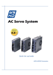
8.5
January 30, 2006
Grounding Tree
PicoDAD Ground tree
5V
3.3V
24V
DC/DC
DC/DC
3.3VA
Filter
+
-
Logic Power Supply
24V
Digital
Single Ground plane
GND
GND
Power
Connected to spacer
DC/DC
D
15V
Bus Power Supply
GND
GND
S
G
+48V
FET Driver
SD
Motor
G
Connected to heat sink
GND
8.6
Electrical Interfaces
8.6.1 Over-Travel Limits and Home
3V3
Mx_Common
1
4
2
3
1
4
2
3
4.7KR
to FPGA
330pF
10K
DGND
Mx_in
2.4K/250mW
3V3
4.7KR
to FPGA
330pF
10K
DGND
Mx_in
2.4K/250mW
PicoDAD-SN User Manual
Page 33 of 130
Danaher Motion Kollmorgen
January 30, 2006
8.6.2 Remote Enable
3V3
In_Common x
10KR
Ena_M0
1
4
2
3
1
4
2
3
to FPGA / DSP
2.4K/250mW
330pF
10KR
DGND
3V3
10KR
Ena_M1
to FPGA / DSP
2.4K/250mW
330pF
10KR
DGND
8.6.3 General-Purpose Inputs
3V3
In_Common x
10KR
In X
1
4
2
3
1
4
2
3
to FPGA
2.4K/250mW
330pF
10KR
DGND
3V3
10KR
In X
to FPGA
2.4K/250mW
330pF
10KR
DGND
8.6.4 General-Purpose Outputs
Out x
28V
From FPGA
1
4
150R
Out_Common
PicoDAD-SN User Manual
3
2
DGND
Page 34 of 130
Danaher Motion Kollmorgen
January 30, 2006
8.6.5 High Speed Inputs
Fast In
150R
2
1
4
12
Fast In\
VCC
VCC
IN+
INCON
CON
1KR
3
OUT
To FPGA
8.6.6 High Speed Outputs
Fast Out
14
13
150R
OUT
OUT
IN
EN
EN
Fast Out\
15
From FPGA
4
12 100R
VCC
VCC
8.6.7 Analog Inputs
The Analog inputs are differential, but the common mode is limited. The AGND pin should be connected to
the ground of the analog command source.
1
GND
8
2.4K
GND
4
4.7nF
8
2
3
1
To DSP ADC
8
5
1
10.0K
4
10.0K
7
6
2
10.0K
3
10.0K
+
Ain_n
7
-
Ain_p
4.7nF
GND
2
2.4K
VCC
Reference voltage
PicoDAD-SN User Manual
Page 35 of 130
Danaher Motion Kollmorgen
January 30, 2006
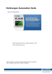
8.6.8 Fault Relay
RLY_C
VCC
2
3
4
RLY_NO
9
8
7
+ 1
10
470R
flt_relay (FPGA)
4.7KR
DGND
DGND
8.6.9 Brake Relay
VCC
Brake1
2
3
4
26V
9
8
7
1 +
10
-
From FPGA
Brake2
1.1A resetable
470R
DGND
8.6.10 Sine Encoder
8.6.11 Halls
8.6.12 Quadrature Encoder
PicoDAD-SN User Manual
Page 36 of 130
Danaher Motion Kollmorgen
January 30, 2006
9. System Operation
9.1
Powering Up
One of the characteristics of SynqNet drives is that at power up, the drive DSP is held in a RESET state
by the SynqNet FPGA in the drive. The DSP reset is only released when a SynqNet RESET command is
issued from the controller. Once this is done, the drive will come up.
The SynqNet RESET can be done in two ways:
9.2
Using MotionConsole: Click on the RESET button in the Controller Summary window (on the
ACTIONS tab)
Using a DOS command:
o
Open a DOS PROMPT window in the * XMP\ Bin\ WinNT folder
o
Type RESET at the command prompt
SynqNet Utilities
A set of SynqNet utilities is installed in the *\XMP\BIN\WINNT folder. These utilities can be used to
perform many drive configuration operations over SynqNet. This manual references many of these utilities,
but provides, for the purposes of legibility, only an abbreviated description of their syntax. The complete
syntax is found on the Motion Engineering support web site, at http://support.motioneng.com/. Reference
should be made to the web site for complete syntax information.
9.3
Rotary Switch Configuration
The PicoDAD is equipped with a 16-pole rotary switch, accessible from the top of the unit. The switch has
no functional use for either the drive or the network. It can be used at the application level to identify
specific nodes on a network.
Caution: The switch must be set to a non-zero value. Setting it to zero causes the
SynqNet RESET to be bypassed, and the drive will not function correctly on the
SynqNet network.
9.4
Current Scaling
The torque command from the controller is multiplied by 0.8 in the drive, and resultant value is used as the
torque command within the drive. That is:
Drive internal torque command = Controller torque command * 0.8
The reasoning is as follows:
The torque command from the motion controller is a value in the range –32768 to +32767, while currents
in the drive are referenced to the drive peak current, DIPEAK.
While DIPEAK represents the absolute maximum current that can be commanded by the drive, the drive is
designed to be able measure actual current 25% above DIPEAK. This is done in order to be able to
measure, and control, current overshoots. Thus, the maximum current that can be represented in the drive
is DIPEAK*1.25.
The torque command from the motion controller must be scaled to the maximum current that the drive can
represent, which is DIPEAK*1.25. However, the controller should not be able to command current above
DIPEAK. Thus, the torque command from the controller is multiplied by 0.8.
PicoDAD-SN User Manual
Page 37 of 130
Danaher Motion Kollmorgen
January 30, 2006
A full-scale torque command of 32767 is thus interpreted in the drive as 26213, and this value is
equivalent to DIPEAK, as shown in the following diagram.
Controller current
command (DAC output)
Drive current
command
32767
32767 = 1.25*DIPEAK
32767*0.8 = DIPEAK
To allow current
feedback overshoot
-32767*0.8 = -DIPEAK
-32767
-32767 = -1.25*DIPEAK
Figure 9-1: Current Scaling
9.5
PWM Saturation
The PWM saturation level is 92.5%. This affects the useable bus voltage. With a 48V input and with PWM
saturation set to 92.5%, the effective bus voltage is 44.4V. This affects the maximum achievable speed.
9.6
Drive Parameters
The drive functionality is set using various drive parameters and instructions, which are communicated
over SynqNet. Parameters may be subject to read-only access, or may be available for read/write access.
The parameters can be stored in non-volatile memory in the drive, to be used on each power-up.
Examples of read-only parameters are: amplifier current rating, absolute current limit, and analog input
values. Examples of read/write drive parameters are: motor current rating, application current limit and
encoder resolution.
Drives are shipped from the factory with motor parameters set to zero and application parameters set to
their default values.
Parameters are identified both by their mnemonics and by an index. It is the index that is used when
accessing a parameter over SynqNet. A list of parameters appears in Section titled Instruction Set.
Drive parameters are implemented for particular drive models and firmware versions; the supported
parameter set may be different for different version of firmware.
The MPI library contains a general drive parameter interface, able to handle any set of drive parameters,
independent of the MPI library version. It uses a drive parameter map file to determine the valid drive
parameters. Individual drive parameters can be set (or read) using MPI methods or the sqDriveParam
utility program. A list of drive parameters can be set (or read) using MPI methods or the sqDriveConfig
utility program.
PicoDAD-SN User Manual
Page 38 of 130
Danaher Motion Kollmorgen
January 30, 2006
The following sections describe the syntax of utilities used when accessing parameters. These utilities are
typically executed from a DOS window in the XMP\BIN\WINNT directory. For application programming
methods, please refer to the Motion Engineering support website: http://support.motioneng.com.
9.6.1 Memory Operations on Drive Parameters
As described in the section on the Drive Processor Memory Description, the drive firmware runs using
parameters stored in RAM. These parameters can, however, be saved in non-volatile memory (E2PROM),
from where they would be loaded into RAM upon power up. The non-volatile memory can also be cleared.
Parameters may be reset to their default values, and a set of saved parameters may be loaded from the
non-volatile memory into the RAM.
The operations described above are executed using SynqNet Direct Commands. The following table
summarizes these commands. The command mnemonic serves to identify the specific command. It also
indicates the syntax of the command used when communicating with the drive over the serial port.
Description
Command
Mnemonic
SynqNet Direct
Command
Notes
Save Parameters
SAVE
0x1C
Save all parameters to nonvolatile memory
Clear non-volatile
memory
CLREEPROM
0x1F
Clear contents of non-volatile
memory. CLREEPROM sets all
parameters to their default
values, and sets motor
parameters to the value zero
Reset parameters to
default
RSTVAR
0x1D
Reset application parameters to
their default values. This
command does not affect motor
parameters
Load parameters from
memory
LOAD
0x1E
Load a set of saved parameters
from non-volatile memory.
Both the CLREEPROM command (Direct Command 0x1F) and the RSTVAR command (Direct Command
0x1D) return parameters to their default values. The difference, however, is that RSTVAR does not affect
motor or current limit parameters. The specific parameters not affected by RSTVAR are:
Motor Parameters
MIPEAK, MICONT, MPITCH, MOTORTYPE, MSPEED, MKT, MBEMF, MENCRES, MSININT,
MENCTYPE, MENCOFF, MPHASE, MPOLES, MBEMFCOMP, MLMIN, MLGAINC, MLGAINP,
MTANGLC, MTANGLP, MVANGLH, MVANGLF
Current Limit Parameters
ILIM, ICONT
Foldback Parameters
FOLDD, FOLDR, FOLDT
9.6.2 Accessing Individual Parameters
Use the sqDriveParam utility for accessing individual parameters. For the syntax below the following
conventions hold:
PicoDAD-SN User Manual
Page 39 of 130
Danaher Motion Kollmorgen
January 30, 2006
x is the node number. Nodes are numbered from 0.
y is the drive, or axis, number on that node. Drives are numbered from 0.
<parameter index> identifies the parameter being accessed
<data value> is the data being written to the parameter
<map file name> is the name of the map file being used.
Syntax for reading drive parameters:
sqdriveparam -node x -drive y -read <parameter index>
Syntax for writing drive parameters:
sqdriveparam -node x -drive y -write <parameter index> -data <value>
Examples:
Read the value of the drive rated peak current:
sqdriveparam -node x -drive y -read 0x3
Set the encoder resolution to 2048:
sqdriveparam -node x -drive y -write 0x7 -data 2048
9.6.3 Accessing an Entire Parameter Set
Use the sqDriveConfig utility for reading or writing an entire set of drive parameters. The utility uses a
map file (see next section) that contains definitions and properties of the drive parameters. The map file
needs to match the drive processor firmware version in terms of version number and in terms of the set of
supported parameters.
Syntax for reading an entire set of parameters to a file:
SqDriveConfig –node x –drive y –get <destination file name> -map <map file name>
Syntax for writing an entire set of parameters from a file:
SqDriveConfig –node x –drive y –set <source file name> -map <map file name>
9.6.4 Drive Parameter Map File
The drive parameter map file is a text file that contains a list of valid drive parameters for a particular drive
model. The file contains five sections: File Header, Drive Identification, Parameter Identification,
Configuration and File Footer. Each Drive Identification section is matched with a Parameter Identification
section and a Configuration section. There may be more than one such set of sections for a specific drive,
allowing for different parameter sets being supported by different firmware versions.
The format is described below. Words in Italics indicate items that are file-specific. A sample map file, for
firmware version 0.1.9, is shown in the appendix Drive Parameter Map File
Note: The drive parameter map file is distributed with the MEI software installation.
For the PicoDAD, the relevant map file is called "Kollmorgen_Picodad.dm", and it is
generally located in the \XMP\BIN directory. Map files are matched to drive
firmware versions. The most up to date map files can be found on the MEI Support
Website, at
http://support.motioneng.com/Downloads-Notes/Firmware/fw_picodad.htm
PicoDAD-SN User Manual
Page 40 of 130
Danaher Motion Kollmorgen
9.6.4.1
January 30, 2006
File Header
The file header contains one line, and is always
#MPI Drive Parameters
9.6.4.2
Drive Identification Section
This section contains one line, describing The name of the manufacturer, the model number, and the drive
firmware versions that are compatible with the drive parameter list.
#”Manufacturer and Model” “drive firmware version”
For the PicoDAD, the “Manufacturer and Model” text will always be “Kollmorgen PicoDAD”
Example:
# "Kollmorgen PicoDAD" "0.1.9"
9.6.4.3
Parameter identification Section
This section contains definitions of the parameters that are valid for the firmware version(s) listed in the
Drive Identification section. The section begins with a header, as follows:
#parameters
Each line in this section contains the following parameter identification information, separated by
whitespaces:
number
drive parameter number (in hex)
name
drive parameter name, or mnemonic
read/write access
read/write (rw) or read-only (ro)
data type
one of the pre-defined data types (see table below)
values
list of valid values, range of valid values, or an address
default value
parameter value to be used if value is not specified
help string
simple string to provide user help
PicoDAD-SN User Manual
Page 41 of 130
Danaher Motion Kollmorgen
January 30, 2006
All service commands and drive parameters are accessed over the service channel as 32 bit quantities,
but these 32bits of data can represent many different types of data. To support various data types with
generic software tools, the supported data types have been predefined. Here are the data type names
that are supported for the drive parameter map file.
Name
unsigned8
unsigned16
unsigned32
signed8
signed16
signed32
hex32
enumerated
mask
character
single
action
Description
An 8-bit unsigned binary number
A 16-bit unsigned binary number
A 32-bit unsigned binary number
An 8-bit binary, twos-complement number
An 16-bit binary, twos-complement number
An 32-bit binary, twos-complement number
An 32-bit unsigned hexadecimal number (same as unsigned32 but displayed as
hexadecimal)
A list of numbers 1,2,3,4 where each number has a specific meaning (same as
unsigned32 but displayed as a selectable list)
A set of bits 1, 2, 4, 8 where each bit has a specific meaning (same as
unsigned32 but displayed as a set of selectable flags)
An ASCII character
A 32-bit floating pint number according to IEEE754
A write-only parameter where the data is always zero. Performs an
action/command on the drive that does not need any data.
A few examples from the PicoDAD are:
0x01 MBEMFCOMP
0x02 DICONT
0x03 DIPEAK
0x04 ICONT
9.6.4.4
rw signed16
ro signed16
ro signed16
rw signed16
{0-100}
{10-1100}
{10-1100}
{0-1000}
0 "Back EMF compensation percentage"
0 "Drive rated continuous current"
0 "Drive rated peak current"
0 "Application rated continuous current"
Configuration Section
The Configuration Section lists the parameters that will be downloaded to a drive from a drive
configuration file or uploaded from a drive to a configuration file, using the sqDriveConfig utility. The
section begins with a header, as follows:
#config
The header is followed by a list of drive parameter names (names only; not values). For example:
MPITCH
MOTORTYPE
MIPEAK
MICONT
// – Indicates a comment and the line is ignored by the parser.
The sequence of names does not need to correspond to the sequence in the Parameter identification
section. It does, however, need to follow the sequence of parameters required by the drive.
PicoDAD-SN User Manual
Page 42 of 130
Danaher Motion Kollmorgen
9.6.4.5
January 30, 2006
File Footer
#end – Designates the end of the parameter map file.
9.6.5 Drive Configuration File
The drive configuration file contains the actual parameter values. The file has a one-line header that
identifies the node and drive number, the drive identification, and the firmware version number. Thus, the
drive configuration file has to be matched to the map file, the firmware version of the drive being
addressed, and the location of that drive on the SynqNet network.
An example of the header line is:
# sqNode[0] drive[1] "Kollmorgen PicoDAD" "0.1.9"
This header shows that the file contains data for the second axis of the PicoDAD that is located on Node
0. Axes in the PicoDAD are numbered 0 and 1 respectively. The header also specifies that the drive has
firmware version 0.1.9.
The rest of the file consists of parameter mnemonics followed by their values. A sample parameter file is
shown in the appendix Sample Drive Configuration File.
The easiest way to create a template for the drive configuration file is to read a file of data from a drive. Of
course, the map file must exist and must be valid.
9.7
Motor Position
9.7.1 Position Feedback Parameter
The motor feedback device is read and processed by the drive processor, and stored in a drive parameter
called PFB (Position Feedback). This is a 32-bit signed value, and may be read over the serial port or over
SynqNet. This is the position value that the drive communicates to the motion controller for use in closing
the position loop.
PFB
Parameter Index
Data Access
Units
Default
Position feedback. Displays the cumulative position feedback from the
feedback device.
0x19
0.0.1
Firmware Version
Read only
32-bit signed
Data Type
Integer
Encoder counts
-2147483648
Range
to
2147483647
Set to 0 at power up for
No
EEPROM
incremental quad or sine
encoder and for resolver.
For EnDat, the value at
power up is based on the
value read from the EnDat
encoder (see HWPOS)
PicoDAD-SN User Manual
Page 43 of 130
Danaher Motion Kollmorgen
January 30, 2006
9.7.2 Mechanical Position
Sets the absolute position feedback of the hardware feedback device (for
both resolver and encoder based systems). PRD will increment from 0 to
65,535 throughout the course of one mechanical motor shaft revolution (360
degrees). The range of PRD will not change. Its resolution for resolver
feedback systems is dependent upon the value of RDRES:
PRD
•
RDRES = 12, resolution of PRD = 16 counts
RDRES = 13, resolution of PRD = 8
RDRES = 14, resolution of PRD = 2
For encoder-based systems, until the encoder has been initialized, PRD will
be un-initialized and its value will not be useful or meaningful. The encoder is
initialized once the first Hall transition has passed.
0x4d
0.1.9
Firmware Version
Read
Integer
Data Type
N/A
0 to 65,535
Range
N/A
No
EEPROM
Parameter Index
Data Access
Units
Default
9.7.3 Position Resolution
The position resolution, expressed as the number of equivalent encoder counts per motor revolution, is set
and calculated differently for each type of feedback device.
Feedback type
Relevant Parameters
Resolution Calculation
Quad Encoder
MENCRES
MENCRES * 4
Resolver
RDRES
RDRES=12 -> 4096 counts per rev
RDRES=13 -> 8192 counts per rev
RDRES=14 -> 16384 counts per rev
Sine Encoder
MENCRES, MSININT
MENCRES * MSININT * 4
9.7.4 Timing of the Position Update
The drive processor reads the feedback device every 62.5μseconds. For quadrature encoder feedback,
the position is available in the same sample. For Resolver and Sin Encoder, however, the position is
generated by a process of interpolation, and the position is available with a delay on one 62.5μsecond
sample. An additional 62.5μseconds delay is introduced because of a delay of one sample in writing the
data to the SynqNet FPGA. The following table shows the estimated position delays:
Feedback Type
Delay in position being written to the FPGA
Quad Encoder
62.5μseconds
Resolver
125μseconds
Sine Encoder
125μseconds
9.8
Drive Configuration
The axes on the PicoDAD are configured via a set of parameters. This section describes how to set these
parameters, and other operations related to them such as saving them in memory. The parameters are
grouped by function.
PicoDAD-SN User Manual
Page 44 of 130
Danaher Motion Kollmorgen
January 30, 2006
9.8.1 The CONFIG Function
The drive’s current loop structure is not directly accessible by the user. Instead of setting PID parameters,
for example, the current loop is configured internally based primarily on motor parameters. When entering
motor parameters, or other parameters that affect the behavior of the current loop, the drive with enter a
state that is called NO-COMP, short for No Compensation. This means that the current loop is not
compensated. In this state the drive is a no-comp fault state, as indicated by an alternating ‘-‘ and ‘1’ on
the 7-segemnt LED, and is not available for controlling motion. The CONFIG command must be executed
in order to configure the current loop and return the drive to an operable state. This command is accessed
via Direct Command 0x20.
Note: To configure the drive, set all the parameters and then execute the CONFIG
instruction
9.8.2 Motor Parameters
MPITCH
Parameter Index
Data Access
Units
Default
MPITCH is a variable for use with linear motors (MOTORTYPE = 2). It defines the
pole- pitch (length in millimeters of one electrical cycle - 360 electrical degrees) of the
motor and allows the drive to calculate other variables (such as velocity). The drive
assumes a ‘no- comp’ state after an entry of this parameter and requires the CONFIG
command.
0x23
Firmware Version
0.0.1
Read/Write
Data Type
Integer
Millimeters per 360 electrical
Range
1 to 500
degrees
0
EEPROM
Yes
MOTORTYPE Sets the drive control algorithms to different motor types. When working with Linear
Parameter Index
Data Access
Units
Default
MIPEAK
Parameter Index
Data Access
Units
Default
motors, the motor pitch (MPITCH) must also be set.
NOTE: For firmware versions up to and including 1.0.0.0, support for Linear Motors is
not provided. This may be added in future versions.
MOTORTYPE 3 should be used with Kollmorgen AKM motors only. In this case, the
drive configures the commutation phasing internally such that the MPHASE parameter
can be set to zero.
0x27
Firmware Version
0.0.1
Read/Write
Data Type
Integer
N/A
Range
0 – Rotary
2 – Linear
3 – Kollmorgen AKM
0
EEPROM
Yes
Sets the motor’s rated peak current. When this variable is set, the drive enters a nocomp state, requiring a CONFIG command
0x0A
Firmware Version
0.0.1
Read/Write
Data Type
Integer
Amperes RMS * 0.1
Range
10 to 3,500
0
EEPROM
Yes
PicoDAD-SN User Manual
Page 45 of 130
Danaher Motion Kollmorgen
MICONT
Parameter Index
Data Access
Units
Default
MSPEED
Parameter Index
Data Access
Units
Default
MJ
Parameter Index
Data Access
Units
Default
MPOLES
Parameter Index
Data Access
Units
Default
January 30, 2006
Sets the motor’s continuous rated current. When this variable is set, the drive enters a
no- comp state, requiring a CONFIG command
0x09
Firmware Version
0.0.1
Read/Write
Data Type
Integer
Amperes RMS * 0.1
Range
10 to 1750
0
EEPROM
Yes
Defines the maximum recommended velocity of the Motor. When this variable is set,
the drive enters a no-comp state, requiring a CONFIG command.
This parameter is used in velocity phase advance calculations.
0x11
Firmware Version
0.0.1
Read/Write
Data Type
Integer
Rotary: RPM
Range
10 to 32767
Linear: mm/sec
0
EEPROM
Yes
Sets the combined inertia of the motor and the load. For rotary motors, the motor
inertia is that of the rotor, and for linear motors the motor inertia refers to the motor coil
mass (linear motors, MOTORTYPE= 2). This parameter is necessary when “Wake-NoShake” encoder commutation initialization is used.
0x32
Firmware Version
0.1.1
Read/Write
Data Type
Integer
rotary: Kg * m2 * 10-6
Range
0 to 2,000,000,000
linear: grams
0
EEPROM
Yes
Sets the number of motor poles. This variable is used for commutation control and
represents the number of individual magnetic poles of the motor (not pole pairs). When
this variable is set, the drive enters a state, requiring a CONFIG command. When
MOTORTYPE = 2 (Linear Motor), this variable must be set to a value of 2.
0x10
Firmware Version
0.0.1
Read/Write
Data Type
Integer
Poles
Range
2 to 80 (even values)
0
EEPROM
Yes
PicoDAD-SN User Manual
Page 46 of 130
Danaher Motion Kollmorgen
January 30, 2006
9.8.3 Feedback Parameters
FEEDBACK
Sets feedback type. This parameter must be matched with type of feedback
connected to the axis. Always disconnect the feedback before making
changes to this parameter.
Parameter Index
Data Access
Units
0x43
Read/Write
N/A
Firmware Version
Data Type
Range
Default
0
EEPROM
MENCTYPE
Sets the motor encoder type when using Quadrature or Sine Encoder
feedback. This parameter is ignored when using Resolver feedback.
When this variable is set on an encoder-based system, the drive enters a nocomp state, requiring a CONFIG command.
0x24
0.1.0
Firmware Version
Parameter
Index
Data Access
Units
Default
Read/Write
N/A
Data Type
Range
0
EEPROM
1.0.0
Integer
0 - Not defined
1 - Resolver
2 - Encoder
3 - Sine encoder
4 - Halls only
Yes
Integer
0 (A/B/I with Halls)
3 (A/B only; phasefinding is triggered by
the phase-finding
routines in the motion
controller)
4 (A/B only; phasefinding is triggered by
Enable)
6 (A/B with Halls)
9 (EnDat)
Yes
Notes on MENCTYPE:
1) MENTYPE values 0 and 6 are supported for quadrature encoder feedback only
(and not for sine encoder).
2) When using an encoder that has A/B signals only, commutation initialization by
moving the motor a few electrical degrees. The drive takes control over the motion
of the motor during this process. Refer to the section on Commutation Initialization
without Halls
PicoDAD-SN User Manual
Page 47 of 130
Danaher Motion Kollmorgen
MENCRES
Parameter Index
Data Access
Units
Default
HALLS
Parameter
Index
Data Access
Units
January 30, 2006
Sets the resolution of the motor encoder in number of lines per revolution of
the motor (in the case of a rotary motor) or number of lines per motor pitch (in
the case of linear motors). This parameter is used when working with
quadrature or sine encoder feedback.
For an incremental encoder, the number of encoder counts per revolution or
per pitch is obtained by multiplying MENCRES by 4.
For a sine encoder, the number of encoder counts per revolution is obtained
by multiplying MENCRES by MSININT and by 4. The equivalent number of
counts per revolution is limited by
MSININT * MENCRES <= 230
Setting this value puts the drive into a no-comp state, and requires execution
of the CONFIG command to release the drive from this state.
0x07
Firmware Version
0.0.1
Read/Write
Data Type
Long Integer
Rotary: Lines per motor
Range
100 to 10,000,000
revolution
Linear: Lines per motor pitch
0
EEPROM
Yes
Returns the hall switch values (encoder feedback option only). The switch
values are displayed as a three-bit code in the sequence C- B- A.
Although the range of values that can be read is 0 through 7, the values 0 and
7 are illegal; the 3 HALL signals should never all have the same state.
The HALL states can also be seen in Motion Console, in the Motor Summary
I/O window
0x44
0.0.1
Firmware Version
Read only
N/A
Data Type
Range
Default
N/A
EEPROM
HALLSTYPE
Sets the type of electrical signal used by the Halls. This option is relevant only
when using quadrature encoder feedback.
0x6D
Firmware Version
0.0.4.3
Parameter
Index
Data Access
Units
Integer
0 to 7, expressed as
a bit-wise value.
No
Read/Write
N/A
Data Type
Range
Default
0
EEPROM
MHINVA
MHINVA is a variable that applies to encoder- based systems that use hall
switches to commutate. This variable inverts the hall sensor A feedback,
causing the system to read the ‘A’ hall channel as inverted data.
0x1E
Firmware Version
0.0.1
Parameter
Index
Data Access
Units
Default
Read/Write
N/A
Data Type
Range
0
EEPROM
PicoDAD-SN User Manual
Boolean
0 (differential)
1 (single-ended)
Yes
Boolean
0 (not invert)
1 (invert)
Yes
Page 48 of 130
Danaher Motion Kollmorgen
MHINVB
Parameter
Index
Data Access
Units
January 30, 2006
MHINVB is a variable that applies to encoder- based systems that use hall
switches to commutate. This variable inverts the hall sensor B feedback,
causing the system to read the ‘B’ hall channel as inverted data.
0x1F
Firmware Version
0.0.1
Read/Write
N/A
Data Type
Range
Default
0
EEPROM
MHINVC
MHINVC is a variable that applies to encoder- based systems that use hall
switches to commutate. This variable inverts the hall sensor C feedback,
causing the system to read the ‘C’ hall channel as inverted data.
0x20
Firmware Version
0.0.1
Parameter
Index
Data Access
Units
Boolean
0 (not invert)
1 (invert)
Yes
Read/Write
N/A
Data Type
Range
Default
0
EEPROM
MSININT
This parameter is used with the sine encoder option and sets the interpolation
level of the drive. The equivalent number of counts per revolution is calculated
from
MSININT * MENCRES * 4
The equivalent number of counts per revolution is limited by
MSININT * MENCRES <= 230
0x41
Firmware Version
Parameter
Index
Data Access
Units
Default
Read/Write
N/A
Data Type
Range
256
EEPROM
PicoDAD-SN User Manual
Boolean
0 (not invert)
1 (invert)
Yes
Integer
1, 2, 4, 8, 16, 32, 64,
128, 256, 512
Yes
Page 49 of 130
Danaher Motion Kollmorgen
January 30, 2006
The following parameters must be set when using resolver feedback.
RDRES
Parameter
Index
Data Access
Units
Sets the resolution of the resolver feedback in resolver systems. The value is
in bits, and indicates how many equivalent encoder counts there are per
mechanical revolution.
Higher resolution may also result in greater noise on the feedback signal.
0x4B
0.1.6
Firmware Version
Read/Write
N/A
Data Type
Range
Default
14
EEPROM
RESBW
Sets the bandwidth of software resolver mechanism. As a general rule of
thumb, set RESBW to 4 or 5 times the velocity loop bandwidth.
0x4C
0.1.6
Firmware Version
Parameter
Index
Data Access
Units
Default
Read/Write
N/A
300
Data Type
Range
EEPROM
Integer
12 (4096 counts per
rev)
13 (8192 counts per
rev)
14 (16384 counts per
rev)
No
Integer
200 to 800
Yes
9.8.4 Current Loop Parameters
The Current controller gain is proportional to (G*I*L/V), where
¾
I is the drive peak current rating (as given by the DIPEAK parameter)
¾
L is the line-to-line inductance (set by the MLMIN parameter)
¾
V is bus voltage (set by the VBUS parameter)
¾
G is the adaptive gain (set by the MLGAINC and MLGAINP parameters)
MLGAINC sets the adaptive gain at motor continuous current (MICONT), and MLGAINP sets the adaptive
gain at motor peak current (MIPEAK).Together, with unity gain at zero current, they creates two piece
linear curve, where the drive calculates the adaptive gain for a given motor current. The current-based
adaptive gain algorithm is a gain calculation method that increases current loop stability by reducing the
current loop gain as the motor current increases (there are motors that their magnetic flux decreases when
the current increases, and so their gain increases). A value of 10 (unity gain) is a good starting point.
PicoDAD-SN User Manual
Page 50 of 130
Danaher Motion Kollmorgen
MLMIN
Parameter Index
Data Access
Units
Default
VBUS
Parameter Index
Data Access
Units
Default
MLGAINC
Parameter Index
Data Access
Units
Default
MLGAINP
Parameter Index
Data Access
Units
Default
PWMFRQ
Parameter Index
Data Access
Units
Default
January 30, 2006
Sets the motor’s minimum line- to- line inductance. This variable is used for
current loop controller design and as an input to the Torque Angle Control
algorithms. The current loop gain is directly proportional to the value of
MLMIN. When this variable is set, the drive enters a no-comp state, requiring
a CONFIG command
0x0E
Firmware Version
0.0.1
Read/Write
Data Type
Integer
Milli-Henries *10–2
Range
1 to 32,767
0
EEPROM
Yes
Sets the drive bus voltage. This variable is used for current controller design.
The current loop gain is inversely proportional to the value of VBUS. VBUS
also affects the value of VMAX (see VMAX). When this variable is set, the
drive will enter a no- comp state, requiring a CONFIG command.
0x17
Firmware Version
0.0.1
Read/Write
Data Type
Integer
Volts
Range
10 to 850
48
EEPROM
Yes
Sets the current loop adaptive gain value at continuous motor current. When
this variable is set, the drive enters a no-comp state, requiring a CONFIG
command
0x0C
Firmware Version
0.0.1
Read/Write
Data Type
Integer
% * 10
Range
1 to 100
8
EEPROM
Yes
Sets the current loop adaptive gain value at peak motor current. When this
variable is set, the drive enters a no- comp state, requiring a CONFIG
command
0x0D
Firmware Version
0.0.1
Read/Write
Data Type
Integer
% * 10
Range
1 to 100
4
EEPROM
Yes
PWM frequency. This value generally set by the drive according to the power
stage being used
0x16
Firmware Version
0.1.6
Read only
Data Type
Integer
KHz
Range
16
16 kHz
EEPROM
No; set by Hardware
PicoDAD-SN User Manual
Page 51 of 130
Danaher Motion Kollmorgen
January 30, 2006
9.8.5 Phase Advance Parameters
The torque-based phase advance helps to achieve higher torque for a given motor current. Usually, it is
applicable for buried magnet rotor (as opposed to surface mounted magnet rotor). For a surface mounted
magnet rotor the MTANGLx parameters should be set to 0. However, if MVANGLx parameters were not
set optimally, non-zero MTANGLx parameters can help to get more torque.
MTANGLC sets the phase advance angle at motor continuous current (MICONT) in electrical degrees,
and MTANGLP sets the phase advance angle at motor peak current (MIPEAK) in electrical degrees.
Together, with zero angle advance at zero current, it creates two piece linear curve, where the drive
calculates the phase advance for a given motor current.
MTANGLC
Parameter Index
Data Access
Units
Default
MTANGLP
Parameter Index
Data Access
Units
Default
Sets the value of the torque-related commutation angle advance at the
motor’s continuous current rating.
0x12
Firmware Version
0.0.1
Read/Write
Data Type
Integer
Electrical degrees
Range
0 to 45
10
EEPROM
Yes
Sets the value of the torque-related commutation angle advance at the
motor’s peak current.
0x13
Firmware Version
0.0.1
Read/Write
Data Type
Integer
Electrical degrees
Range
0 to 45
23
EEPROM
Yes
The velocity-based phase advance helps to achieve higher torque for a given motor speed. These
parameters are independent of the rotor magnets. They come to compensate for computing time and
current loop phase lag. In general, they shouldn’t be set to 0.
MVANGLH sets the phase advance angle at half of motor speed (MSPEED/2) in electrical degrees, and
MVANGLF sets the phase advance angle at motor speed (MSPEED) in electrical degrees. Together, with
zero angle advance at zero speed, it creates two piece linear curve, where the drive calculates the phase
advance for a given motor speed.
MVANGLH
Parameter Index
Data Access
Units
Default
MVANGLF
Parameter Index
Data Access
Units
Default
Sets the value of the velocity-rated commutation angle advance to be used
when the motor is operating at half of the motor max speed.
0x15
Firmware Version
0.0.1
Read/Write
Data Type
Integer
Electrical degrees
Range
0 to 90
0
EEPROM
Yes
Sets the value of the velocity-rated commutation angle advance to be used
when the motor is operating at motor max speed.
0x14
Firmware Version
0.0.1
Read/Write
Data Type
Integer
Electrical degrees
Range
0 to 90
0
EEPROM
Yes
PicoDAD-SN User Manual
Page 52 of 130
Danaher Motion Kollmorgen
January 30, 2006
9.8.6 Back-EMF Compensation
The Back-EMF is a feed-forward for the current loop. It takes the velocity, multiplies it by motor torque
constant (set using MKT), and multiplies the result by the specified Back-EMF gain (MBEMFCOMP). Then
it performs commutation (multiplies the above result by the same sin, sin+120, and sin+240, as it
multiplies the current command). The results (one per phase) are added to the output of the corresponding
current controller outputs, and the sums generate the PWM commands for each phase. One can consider
the Back-EMF of the motor as a disturbance to the current loop. The drive has the capability to estimate
the amount of Back-EMF, and to inject feed-forward correction.
Higher currents will be used when Back-EMF compensation is on, since the Back-EMF is a feed-forward
to the current loop. The advantage of using Back-EMF compensation is that it bypass the current
controller with its finite bandwidth (the back EMF comp is a gain only, and has "unlimited" bandwidth). As
the motor speed increases, the commutation frequency increases, the current controller gets closer to its
bandwidth, and the Back-EMF compensation effect is more emphasized. The disadvantage with using
Back-EMF compensation is that it injects noise since it has "unlimited" bandwidth. As always, a balance
needs to be found.
Since the torque constant and the back-EMF constant are equivalent, either the torque/force constant can
be set, using the MKT parameter, or the back-EMF constant can be set, using the MBEMF parameter.
MBEMFCOMP Sets the amount of BEMF compensation. This variable affects the amount of back
EMF compensation that is applied to the motor command.
You can consider the BEMF of the motor as a disturbance to the current loop. The
drive has the capability to estimate the amount of BEMF, and to inject feed-forward
correction.
MBEMFCOMP=0 means no BEMF compensation.
MBEMFCOMP=100 means that BEMF compensation equals to the estimated BEMF.
Typical values of MBEMFCOMP are 50 to 80.
Parameter Index
Data Access
Units
Default
0x01
Read/Write
Percent
0
MKT
Sets the motor’s torque or force constant. MKT is part of the Back EMF compensation
algorithm. This parameter can be set in place of MBEMF, in cases where the torque
or force constant is specified.
The conversion from back-EMF constant to torque constant is done as follows:
Rotary: MKT = MBEMF * 16.55
where MBEMF is in units of V/1000RPM
Linear: MKT = MBEMF * MPITCH * 16.55 / ( 60 * SQRT(2) )
where MBEMF is in units of V/m/s
To convert from units of lb-in/Amp to N-m/A, multiply by 0.1130
When this variable is set, the drive enters a no- comp state, requiring a CONFIG
command
0x0B
Firmware Version
0.0.1
Read/Write
Data Type
Integer
Rotary: N * m / (1000 * Amp)
Range
16 to 64,548
Linear: N / (1000 * Amp)
0
EEPROM
Yes
Parameter Index
Data Access
Units
Default
PicoDAD-SN User Manual
Firmware Version
Data Type
Range
EEPROM
0.0.1
Integer
0 to 130
Yes
Page 53 of 130
Danaher Motion Kollmorgen
MBEMF
Parameter Index
Data Access
Units
Default
January 30, 2006
Sets the motor’s Back-EMF constant. MBEMF is part of the Back EMF compensation
algorithm. This parameter can be set in place of MKT, in cases where the back-EMF
is specified.
Motor data sheets often specify the back-EMF constant (MBEMF). The conversion
from back-EMF constant to torque constant is done as follows:
Rotary: MKT = MBEMF * 16.55
where MBEMF is in units of V/1000RPM
Linear: MKT = MBEMF * MPITCH * 16.55 / ( 60 * SQRT(2) )
where MBEMF is in units of V/m/s
To convert from units of lb-in/Amp to N-m/A, multiply by 0.1130
When this variable is set, the drive enters a no- comp state, requiring a CONFIG
command
0x0B
Firmware Version
0.0.1
Read/Write
Data Type
Integer
Rotary: V/1000RPM
Range
1 to 3900
Linear: V/m/s
0
EEPROM
Yes
9.8.7 Current Limits
The drive current limits are set primarily by the drive peak current and drive continuous current ratings
(DIPEAK and DICONT, respectively). The drive current rating is coded in hardware, and these values are
initialized at power up according to that coding. All drive current limits derive from these two values, and all
parameters rated to current are scaled to the value of DIPEAK.
DIPEAK
Defines the rated peak current of the drive. All current values in the drive are scaled to
DIPEAK.
The drive current rating is coded in hardware in the power section of the drive, and read by
the firmware during the power up cycle.
Although the parameter is defined as read-only, writing the same value as that defined in
the hardware will be accepted, and the drive will enter the no-comp fault state. If a value
different from that defined in hardware is written, a “Not Programmable” error will be
returned.
0x03
Firmware Version
0.0.1
Parameter
Index
Data
Access
Units
Read-Only
Data Type
Integer
Amperes RMS * 0.1
Range
Default
Hardware-defined
EEPROM
10 to 2,200
The value ‘200’ implies 20Amp RMS
No
PicoDAD-SN User Manual
Page 54 of 130
Danaher Motion Kollmorgen
DICONT
January 30, 2006
Defines the rated continuous current of the drive.
The drive current rating is coded in hardware in the power section of the drive, and read by
the firmware during the power up cycle.
Although the parameter is defined as read-only, writing the same value as that defined in
the hardware will be accepted, and the drive will enter the no-comp fault state. If a value
different from that defined in hardware is written, a “Not Programmable” error will be
returned.
0x02
Firmware Version
0.0.1
Parameter
Index
Data
Access
Units
Read-Only
Data Type
Integer
Amperes RMS * 0.1
Range
Default
Hardware-defined
EEPROM
10 to 1,100
The value ‘100’ implies 10Amp RMS
No
IMAX
Defines the maximum current that the drive will allow. IMAX is scaled to DIPEAK. It is
calculated as follows:
1. If MIPEAK is greater than or equal to DIPEAK, IMAX is set to 1000 (which represents
100% of the drive peak current)
2. If MIPEAK is less that DIPEAK, IMAX is calculated as follows:
IMAX = MIPEAK/DIPEAK * 1000
0x06
Firmware Version
0.0.1
Parameter
Index
Data
Access
Units
Default
Read-Only
Data Type
Integer
% of DIPEAK * 0.1
0
Range
EEPROM
0 to 1,000
No
9.8.8 Application Current Limits
ILIM
Parameter
Index
Data
Access
Units
Default
Sets the application current limit, allowing the user to limit the drive’s peak current. This
variable limits the current command issued by the control loops. This variable is an
independent variable that is not calculated from hardware parameters and is not tied to any
other variables.
Set ILIM as follows:
1. If MIPEAK is greater than or equal to DIPEAK, set ILIM to 1000 (which represents 100%
of the drive peak current)
2. If MIPEAK is less that DIPEAK, calculate ILIM as follows:
ILIM = MIPEAK/DIPEAK * 1000
0x05
Firmware Version
0.0.1
Read/Write
Data Type
Integer
% of DIPEAK * 0.1
IMAX
Range
EEPROM
0 to IMAX
Yes
PicoDAD-SN User Manual
Page 55 of 130
Danaher Motion Kollmorgen
ICONT
Parameter
Index
Data
Access
Units
Default
January 30, 2006
Sets the system continuous current. This variable is used in the foldback algorithm. The
default value of this variable is the minimum of DICONT (Drive Continuous Current) and
MICONT (Motor Continuous Current), unless that value exceeds IMAX, in which case
ICONT is set equal to IMAX. This variable is reset to its default whenever DICONT or
MICONT is changed. The user can override the default.
0x04
Firmware Version
0.0.1
Read/Write
Data Type
Integer
% of DIPEAK * 0.1
min of DICONT and MICONT
Range
EEPROM
0 to IMAX
Yes
9.8.9 Reading Actual Current
The actual current can be read in two ways:
•
Reading an instantaneous value of the current by querying a drive parameter
•
Getting a continuous reading of current using the real-time monitoring feature.
This section will describe the parameter used to read instantaneous value of current. For continuous
readings, refer to the section on Real-Time Data Monitoring.
I
This parameter reads overall motor current. Motor current is calculated as the rootmean-square of the individual phase currents:
I = ( Ia ^ 2 + Ib^ 2 + Ic ^ 2)
Parameter Index
Data Access
Units
Default
Note that this is an absolute value. Note, too, that it is not in the same units as the
torque command. In order to get a signed value of current, in the same units as the
torque command, the current must be read using the Real-Time Monitoring feature.
0x45
Firmware Version
0.0.2.9
Read-Only
Data Type
Integer
% of DIPEAK * 0.1
Range
0 to 1,000
N/A
EEPROM
No
IA
This parameter reads the instantaneous value of the current on phase A
Parameter Index
Data Access
Units
Default
0x2A
Read-Only
% of DIPEAK * 0.1
0
IC
This parameter reads the instantaneous value of the current on phase C
Parameter Index
Data Access
Units
Default
0x2B
Read-Only
% of DIPEAK * 0.1
0
Firmware Version
Data Type
Range
EEPROM
Firmware Version
Data Type
Range
EEPROM
0.0.1
Integer
0 to 1,000
No
0.0.1
Integer
0 to 1,000
No
9.8.10 Current Measurement Filters
Low-pass filters may be applied to the current measurements in order to reduce noise that may exist on
the measurement or on the motor cables. Two filters exist, one that is applied to phases A and C, and one
that is applied to phase B. The reason for this differentiation is that current is actually measured on phases
A and C, while it is calculated for phase B.
PicoDAD-SN User Manual
Page 56 of 130
Danaher Motion Kollmorgen
January 30, 2006
Note: Using low-pass filters on the current measurement adds phase lag to the
current loop, and results in a slower current loop response. This is not necessarily
good or bad; it just has to be considered within the context of the control system.
IACLPF
Parameter Index
Data Access
Units
Default
IBLPF
Parameter Index
Data Access
Units
Default
Sets the low-pass filter that is applied to the current measurement on phases A and
C.
Setting the value to 0 disables the low-pass filter
0x6B
0.0.2.5
Firmware Version
Read-Only
Integer
Data Type
Hz
0 to 5000
Range
0
Yes
EEPROM
Sets the low-pass filter that is applied to the current measurement on phase B.
Setting the value to 0 disables the low-pass filter
0x6C
0.0.2.5
Firmware Version
Read-Only
Integer
Data Type
Hz
0 to 5000
Range
0
Yes
EEPROM
9.8.11 Current Foldback
Current Foldback is the mechanism by which the drive processor limits the actual current to the rated
continuous current.
The drive’s microprocessor monitors the current feedback signal and develops an RMS value of this signal
for the purpose of providing a value that represents the current in the motor. The system is similar to an I2t
accumulator.
If the actual current exceeds the continuous current rating of the drive/motor combination (ICONT), the
foldback algorithm begins reducing the current towards the ICONT level. When the current starts to
decrease, the drive is said to have entered the Foldback mode. When in the foldback mode, a steady ‘F’ is
displayed on the 7-segment LED, and the Warning bit (bit number 14) is set in the Cyclic Status Flags.
Refer to the section on Warnings.
PicoDAD-SN User Manual
Page 57 of 130
Danaher Motion Kollmorgen
January 30, 2006
The diagram below illustrates the current foldback process:
Figure 9-2: Current Foldback
Current is folded back exponentially from IMAX, where IMAX is the maximum allowed system current limit.
The application current limit is set by the ILIM parameter. ILIM can be set to any value up to IMAX. If ILIM
is less than IMAX, then foldback will, of course, be from the ILIM level and not from the IMAX level. In this
case, foldback will begin after a time that is greater than FOLDD; the exponential current decrease is
always calculated from IMAX.
FOLDD
Parameter Index
Data Access
Units
Default
FOLDT
Parameter Index
Data Access
Units
Default
PicoDAD-SN User Manual
Sets the delay time for drive foldback. This is the minimum amount
of time that the system current can exceed ICONT before the drive
enters the drive foldback state. The delay time assumes a worstcase scenario where the drive is applying IMAX current. A current
level of less than IMAX can be allowed for a longer time.
It is highly recommended to use the default value of this parameter.
0x51
Firmware Version
0.0.1
Read/Write
Data Type
Integer
Milli-seconds
Range
1 to 32,767
1000 – 2000;
EEPROM
Yes
depends on power
stage rating
Sets the time constant for drive foldback. After the drive enters the
drive foldback state, this variable defines how long it will take the
drive to reduce the system current level to ICONT.
0x54
Firmware Version
0.0.1
Read/Write
Data Type
Integer
Milli-seconds
Range
1 to 32,767
1450 – 2500:
EEPROM
Yes
depends on power
stage rating
Page 58 of 130
Danaher Motion Kollmorgen
January 30, 2006
FOLDR
Foldback recovery time
Parameter Index
Data Access
Units
Default
0x53
Read/Write
Milli-seconds
12000 –17000:
depends on power
stage rating
FOLDMODE
Sets the mode for drive current foldback and motor current
foldback operation. Only one value is supported for FOLDMODE
Parameter Index
Data Access
Units
Default
FOLDTIME
Parameter Index
Data Access
Units
Default
Firmware Version
Data Type
Range
EEPROM
0.0.1
Integer
1 to 32,767
Yes
0 = normal foldback from ILIM to ICONT
0x52
Firmware Version
0.0.1
Read/Write
Data Type
Integer
N/A
Range
0 to 0
0
EEPROM
Yes
Sets the time from foldback detection to foldback fault latch, for
FOLDMODE=1 only.
0x55
Firmware Version
0.0.1
Read/Write
Data Type
Integer
Milli-seconds
Range
1 to 300
30
EEPROM
Yes
9.8.12 Application Velocity Limit
VLIM
Sets an application maximum velocity. VLIM is used in the drive
as follows:
1) For velocity calculation and reporting
2) In back-EMF compensation.
3) In speed phase advance.
4) In WNS (commutation initialization) process.
Parameter Index
Data Access
Units
Default
PicoDAD-SN User Manual
The drive supports a large variety of feedback resolutions and
speeds. In order to be able to provide for all options, the drive's
internal velocity variables are scaled so that 16384 internal
bits/250usec are equivalent to VLIM (in RPM). This means that the
lower the VLIM, the better the velocity resolution is. Thus, this
value should be set to maximum application speed.
VLIM is not used directly; rather, the actual velocity is used.
0x28
0.1.0
Firmware Version
Read/Write
Integer
Data Type
Rotary: RPM
10 to VMAX
Range
Linear: mm/sec
10
Yes
EEPROM
Page 59 of 130
Danaher Motion Kollmorgen
January 30, 2006
9.8.13 Under-Voltage Fault Processing
Both the under-voltage trip level, and the drive’s response to an under-voltage situation, can be
programmed.
UVTRESH
Parameter Index
Data Access
Units
Default
UVMODE
Parameter Index
Data Access
Units
Default
UVTIME
Parameter Index
Data Access
Units
Default
UVRECOVER
Parameter Index
Data Access
Units
Default
PicoDAD-SN User Manual
Sets the under-voltage threshold level. This is the voltage at and
below which an under-voltage event will be flagged. The drive’s
response to the event can be programmed using the UVMODE,
UVTIME and UVRECOVER parameters.
0x61
0.1.6
Firmware Version
Read/Write
Integer
Data Type
DC Volts
TBD
Range
36
Yes
EEPROM
Defines how the drive will respond to an under-voltage (UV) fault:
0 = latch fault immediately, display flashing “u”.
1 = display steady “u”. Warning only, with no fault latch.
2 = display steady “u”. After UVTIME elapses, latch fault.
If UVMODE= 1, and the drive is disabled, the UV fault is ignored.
See also UVRECOVER.
0x33
0.1.6
Firmware Version
Read/Write
Integer
Data Type
N/A
0, 1, 2
Range
0
Yes
EEPROM
Sets the amount of time an under-voltage warning is displayed (“u”)
before it is latched when UVMODE=2.
0x34
0.0.2.7
Firmware Version
Read/Write
Integer
Data Type
Seconds
1 to 300
Range
30
Yes
EEPROM
Defines how the drive will recover from an under- voltage (UV)
fault:
0 = recover by executing Clear Faults procedure after the
UV condition clears
1 = automatically recover when the UV condition clears
See also UVMODE.
0x35
0.1.2
Firmware Version
Read/Write
Integer
Data Type
N/A
0, 1
Range
0
Yes
EEPROM
Page 60 of 130
Danaher Motion Kollmorgen
January 30, 2006
9.8.14 Motor Over-Temperature Fault Processing
A motor over-temperature fault can be identified if the motor has a thermal sensor, and if the drive is set
up correctly to interface to this sensor. The following instructions explain how this is done.
The following table defines the behavior of the sensor reading and of the fault as a function of the
THERTYPE setting:
Motor over-temp switch state
THERMTYPE
THERM
Fault
Closed
0
0
No
Closed
1
1
Yes
Open
0
1
Yes
Open
1
0
No
THERMODE
Parameter Index
Data Access
Units
Default
THERMTYPE
Parameter Index
Data Access
Units
Default
THERM
Parameter Index
Data Access
Units
Default
PicoDAD-SN User Manual
Determines the operation of the drive when the Motor Thermostat
Input (THERM) opens.
0 = disable drive and open fault relay immediately
1 = ignore thermostat input
Set this parameter to 1 if the motor does not have thermal sensor,
or if the thermal sensor is not wired. The sensor should be wired
between pins 19 and 20 on the feedback connector.
0x37
0.1.6
Firmware Version
Read/Write
Integer
Data Type
N/A
0, 1
Range
0
Yes
EEPROM
Sets the motor temperature sensor type:
0 = PTC (Positive Temperature Coefficient)
1 = NTC (Negative Temperature Coefficient)
0x38
0.1.1
Firmware Version
Read/Write
Integer
Data Type
N/A
0, 1
Range
0
Yes
EEPROM
Indicates the state of the motor thermostat input.
0 = thermostat input closed (normal).
1 = thermostat input open (overheat condition)
0x36
0.1.6
Firmware Version
Read only
Integer
Data Type
N/A
0, 1
Range
Hardware defined
No
EEPROM
Page 61 of 130
Danaher Motion Kollmorgen
9.9
January 30, 2006
Setting the MPHASE Parameter
9.9.1 Introduction
Brushless sine drives produce electrical commutation to match the motor sinusoidal torque curves. The
PicoDAD performs commutation by using one of several available position feedback devices. The
alignment between the motor electrical position and the commutation-generated current has a significant
effect on operation and performance of the system.
MPHASE tuning is relevant for systems with absolute electrical position sensing, i.e. Resolver,
Incremental Encoder with halls and EnDat sine encoder. For incremental encoder system where no
electrical positioning sensors exist MPHASE should be set to zero, and not tuned.
MPHASE tuning may be required if one of the following occurs:
•
Motor torque is lower than expected.
•
Positive torque causes negative velocity.
•
Motor performance is not symmetrical in both motion directions.
•
There is no torque at any position with non-zero current.
MPHASE tuning will not solve:
•
Motor lockup in certain locations.
•
No motion due to current not flowing through the motor.
•
Motor sometimes operates well and sometimes runs away.
9.9.2 Parameter Definition
MPHASE
Parameter Index
Data Access
Units
Default
Defines the commutation angle offset relative to the standard
commutation. Tuning of MPHASE may be required to achieve
motion in the required direction, and to achieve balanced motion.
0x0F
0.0.1
Firmware Version
Read/Write
Integer
Data Type
Electrical Degrees Range
0 to 359
0
Yes
EEPROM
For EnDat systems,
the value is stored in
the EnDat EEPROM.
The MPHASE parameter can be used to reverse the direction of motion. For example, if a positive torque
command is causing motion in the negative direction, MPHASE can be adjusted by 180 degrees to
reverse the direction of motion.
9.9.3 Calculating MPHASE using the ZERO Procedure
The value of MPHASE can be calculated from results obtained when doing the ZERO procedure. The
ZERO procedure is generally used to align the feedback device to the motor. In this case, we can use it to
calculate the correct value of MPHASE. The procedure uses the PRD parameter, which provides the
absolute position of the feedback device. Refer to details of the PRD instruction.
PicoDAD-SN User Manual
Page 62 of 130
Danaher Motion Kollmorgen
January 30, 2006
Parameter Index
Data Access
Units
Default
Enables and disables feedback Zeroing Mode. If Zeroing Mode is
enabled, the drive rotates the motor to an electrical null by placing
IZERO current from the motor C terminal to the B terminal.
0 = zeroing mode disabled
1 = zeroing mode enabled
0x3A
0.0.2.9
Firmware Version
Read/Write
Integer
Data Type
N/A
0, 1
Range
0
No
EEPROM
IZERO
Sets the C- B phase current for ZERO Mode.
Parameter Index
Data Access
Units
Default
0x39
Read/Write
% of MICONT
25
ZERO
Firmware Version
Data Type
Range
EEPROM
0.0.2.9
Integer
1 to 177
Yes
Caution: When the zeroing mode is enabled, the drive moves the motor without
control from the motion controller. When using this mode, the motion controller
The procedure is as follows:
•
Start the system
•
Ignore index pulse if exists (set MENCTYPE=6 if working with a quad encoder).
•
If working with Halls, make sure a hall transition occurs before proceeding.
•
Set ZERO=1
•
Enable the drive.
•
Increase IZERO to obtain accurate position holding.
•
Query PRD value at the lock position.
•
Query MPOLES value.
•
Follow the formula for computing MPHASE.
MPHASE = -PRD/65536*MPOLES/2*360
•
Add or subtract multiples of 360 so that 0 <= MPHASE < 360
9.9.4 Setting MPHASE with AKM Motors
First, make sure that the motor is wired to the drive according to the descriptions given in the section on
wiring Kollmorgen AKM motors. Next, verify that the MOTORTYPE parameter is set to 3. Then, MPHASE
will be zero.
9.10
Encoder Index Position
For motors that have hall sensors embedded in the motor for commutation initialization, an index signal
may be advantageous in order to improve commutation accuracy, and hence motor-drive efficiency. The
MENCTYPE parameter is used to tell the drive whether it has halls with an index (MENCTYPE=0), or halls
only (MENCTYPE=6).
PicoDAD-SN User Manual
Page 63 of 130
Danaher Motion Kollmorgen
January 30, 2006
9.10.1 The MENCOFF Parameter
When using an index, the position of the index must be known. This position is recorded in the MENCOFF
parameter. The value of MENCOFF is either known from the motor data sheet, or it needs to be detected
by the drive using an Encoder Initialization procedure.
MENCOFF
Parameter Index
Data Access
Units
Default
Sets the encoder index position, and is relevant only for systems that use
encoder feedback, and that use the Index mark. The Index mark is used to
provide a correction to the drive commutation. It should be used when
commutation may suffer from inaccuracies, such as if hall-effect signals are
inaccurate.
This variable is expressed in units of encoder counts after quadrature. If it is
not known from the motor data sheet, it can be set automatically using
ENCINIT.
When this variable is set, the drive enters a no-comp state, requiring a
CONFIG command.
0x08
Firmware Version
Read/Write
Data Type
Long Integer
Encoder counts/ mechanical
Range
0 to (4* MENCRES) –
motor rev
1
0
EEPROM
Yes
Caution: If the encoder index offset is not know from a motor data sheet, do not
attempt to drive the motor until the ENCINIT process has been completed. Doing
so may result in motor run-away when the index mark is crossed.
9.10.2 MENCOFF for Kollmorgen AKM Motors
When using Kollmorgen AKM motors, the value of MENCOFF can be calculated using the following
equation:
MENCOFF = MENCRESx4 / (MPOLES/2) x 240/360
Note that the value for MENCOFF needs to be set explicitly, even when the MOTORTYPE parameter is
set to the value 3.
9.10.3 Encoder Index Initialization
The drive has a procedure called ENCINIT, using which the index position can be automatically
determined. The procedure is as follows:
•
First issue the ENCINIT command.
The drive enters a mode in which it looks for the index mark. The ENCINITST parameter will
return 1.
•
Move the motor manually. When the index is crossed the ENCINITST command will return 2. At
this point MENCOFF is updated to the index location.
•
Save the MENCOFF value by executing the SAVE command.
PicoDAD-SN User Manual
Page 64 of 130
Danaher Motion Kollmorgen
ENCINIT
Parameter Index
Data Access
Units
Default
ENCINITST
January 30, 2006
Execute the encoder initialization procedure, in order to find the
index position. This procedure should be used only when the drive
is configured for working with encoder feedback containing
commutation tracks (or hall-effect signals) and an index signal
(MENCTYPE=0)
This is an “action”-type instruction; it does not read or write a
parameter, but causes a specific action to be take. Use this
parameter as if it were a write-only parameter with a data value of
zero.
0x62
0.0.2.9
Firmware Version
Action
Integer
Data Type
N/A
0
Range
N/A
No
EEPROM
Displays the status of the encoder initialization function. This
variable is reset to 0 when the index position is set manually (see
MENCOFF).
0 = initialization process has not begun
1 = encoder initialization is in progress
Parameter Index
Data Access
Units
Default
PicoDAD-SN User Manual
2 = encoder initialization has been completed
0x63
0.0.2.9
Firmware Version
Action
Integer
Data Type
N/A
0-2
Range
N/A
No
EEPROM
Page 65 of 130
Danaher Motion Kollmorgen
9.11
January 30, 2006
Commutation Initialization with Commutation Signals
9.11.1 The MFBDIR Parameter
MFBDIR
Parameter Index
Data Access
Units
Default
Sets the motor feedback direction. MFBDIR is a bit-wise value, with
bits 0, 1 and 2 being significant. This parameter must be set
correctly to ensure that a positive torque command results in
motion in the positive direction, and vice-versa. When this variable
is set, the drive enters a no-comp state, requiring a CONFIG
command.
Bit 0 – controls the direction of PRD.
0 – Normal, follows the increments of A/B encoder counts.
1 – Reversed, follows the negated increments of A/B encoder
counts.
Bit 1 – controls the direction of PFB.
0 – Normal, follows the increments of A/B encoder counts. Positive
velocity and positive PFB increments for positive increments of A/B
encoder counts.
1 – Reversed, follows the negated increments of A/B encoder
counts. Negative velocity and negative PFB increments for positive
increments of A/B encoder counts.
Bit 2 – controls the inversion of the initial commutation angle,
according to the halls.
0 – Normal, initial commutation angle according hall state.
1 – Reversed, initial commutation angle equals 360 – angle
according hall state.
0x29
0.1.1
Firmware Version
Read/Write
Integer
Data Type
N/A
0 to 7
Range
0
Yes
EEPROM
Note: Set MFBDIR once all other feedback parameters have been set.
9.11.2 For Resolver Feedback
For resolver feedback, no commutation signals or parameters are required, since the resolver sine and
cosine signals themselves provide the commutation initialization information.
9.11.3 For Encoder Feedback with Commutation Signals
The following procedure allows the user to configure drive parameters such that commutation will be
correct. The procedure is valid when the feedback type is Incremental Encoder with Halls (MENCTYPE=0
or MENCTYPE=6). The drive parameters used in this procedure are MPHASE, MFBDIR and MHINVx.
PicoDAD-SN User Manual
Page 66 of 130
Danaher Motion Kollmorgen
January 30, 2006
In addition, the HALLS instruction is used to read the value of the halls sensor states. The HALLS
instruction can be executed from within a MotionLink terminal. The HALL states can also be seen in
Motion Console, in the Motor Summary I/O window. The drive returns a 3-digit value, with each digit being
‘1’ or ‘0’ and representing a hall state. The left-hand digit represents hall sensor C, the middle digit
represents hall sensor B, and the right-hand digit represents hall sensor A. For example the halls sensor
pattern
011
indicates that
Hall C is 0
Hall B is 1
Hall A is 1
This section of the document makes use of a value of the halls sequence, with the value being a decimal
representation of the binary halls states. In the above example, where the HALLS instruction returns the
value ‘011’, the equivalent halls sequence value is 3. Similarly, a HALLS pattern of ‘110’ is equivalent to a
halls sequence value of 6.
Assumption: wiring predefined. Once the motor and feedback have been wired to the drive, no change in
wiring is allowed.
9.11.3.1
Reset Parameters
Set MPHASE=0, MFBDIR=0, MHINVx=0.
9.11.3.2
Identify the direction of motor phases.
Disconnect motor leads from drive.
Use lab power supply with current limit capability.
Apply current (the amount of current is the minimum that still locks the motor firmly) from motor
phase C (connected to the positive terminal of the power supply) to motor phase B (connected to
the negative terminal of the power supply).
Make sure the motor is locked in position.
Apply the same current from motor phase C to motor phase A. The motor should jump 60
electrical degrees.
Watch the direction of the motor jump.
Let define this direction as “positive motor phase direction”.
9.11.3.3
Set MFBDIR bit 2.
Rotate the motor manually slowly to the positive motor phase direction, and monitor the hall state
using HALLS command (from MotionLink Terminal).
Positive hall sequence is {1,5,4,6,2,3}. Check only the sequence, not the start point.
If the hall sequence is backwards, set MFBDIR bit 2 to 1.
Please pay attention that setting this bit doesn’t change the readout of HALLS command.
9.11.3.4
Align the halls to motor phase (set MPHASE).
Apply current from motor phase C to motor phase B (same way as in item 2).
Read hall state.
Try to manually move a bit (right and left) the motor from where it locked, while reading the hall
state, to see if the motor is close to hall edge.
PicoDAD-SN User Manual
Page 67 of 130
Danaher Motion Kollmorgen
January 30, 2006
When current is applied from motor phase C to motor phase B the motor should be locked
between hall states 1 and 3.
Calculate the locking location angle according to the following table:
Hall edge
Angle
Angle
MFBDIR bit 2 = 0
MFBDIR bit 2 = 1
3 and 1
0
0
1 and 5
60
300
5 and 4
120
240
4 and 6
180
180
6 and 2
240
120
2 and 3
300
60
Set MPHASE = 360 – Angle.
If machine positive direction is opposite to motor phase direction, add (or subtract) 180 from
MPHASE.
9.11.3.5
Set MFBDIR bit 0.
Rotate the motor manually one rev (or one pitch). The direction is not relevant.
Rotate the motor manually slowly to the positive motor phase direction, and monitor PRD.
If PRD counts down, set MFBDIR bit 0 to 1.
9.11.3.6
Set MFBDIR bit 1.
Rotate the motor manually slowly to machine positive direction, and monitor PFB.
If PFB counts down, set MFBDIR bit 1 to 1.
9.11.3.7
Operate the system.
Save Settings
At this point, everything should be working properly. Save the settings to the CD's EEPROM
(using the serial SAVE command or the SynqNet 0x1C Direct Command) and to disk.
Confirm Proper Commutation at All Initialization Conditions
Disable the drive. Push the drive by hand until the HALL state is 001. Turn off power to the drive
and wait for the LED display to go blank, and then wait 5 seconds more. Turn on power to the
drive. Slowly increase positive DAC input to the drive until motion just begins in the positive
direction. Slowly decrease negative DAC input to the drive until motion just begins in the negative
direction. The positive and negative DAC values should be approximately the same (assuming
the motor is level). Repeat this process by starting from each of the six Hall states.
Confirm Proper Operation in the Application Conditions
Tune the servo loop. Command aggressive moves and the highest acceleration used by the
application. Observe the peak value of DAC input required for forward and reverse motion.
These values should be approximately the same (within about 10%). If desired/required, adjust
MPHASE up or down to give equal peak DAC output in both directions.
PicoDAD-SN User Manual
Page 68 of 130
Danaher Motion Kollmorgen
9.12
January 30, 2006
Commutation Initialization without Commutation Signals (Phase Finding)
9.12.1 Overview
Servo drives need to know the electrical angle of the shaft so that they can commutate the motor correctly.
If the electrical angle is not known correctly this will result in a reduction of the available torque, the
addition of a static bias to the torque and possibly an inversion of the torque’s polarity. The electrical angle
is available directly if a resolver, commutating encoder or absolute encoder is used. However in certain
circumstances only an incremental position measurement is available and it is necessary to carry out a
process of determining the electrical angle, i.e. “Phase Finding”.
There are various phase-finding techniques; generally they rely on the shaft (or the forcer in the case of a
linear motor) being free of static loads or excessive inertias. If these conditions are met then phase-finding
can be carried out by a technique such as:
•
Applying a forced commutation to move the motor to a predetermined position where the torque
generated is zero and updating controller variables accordingly.
•
Using a motion control algorithm that will “bring” the commutation angle of the motor from the
initial, unknown position to the current motor position (instead of moving the motor).
The disadvantage of the first method is that it requires the motor to be moved, which produces a “jumpy”
motion that may not be tolerable in some cases (for example - linear motor applications).
The second method is designed to solve this problem by implementing a closed loop commutation-lock
algorithm that adjusts the commutation angle to the motor position rather than moving the motor to a
predetermined place. The motor will move very slightly; motion of about ±4 electrical degrees is expected,
but it can also be as high as ±15 electrical degrees.
Phase Finding is commonly used on applications with linear scales. The presence of a static load such as
gravity or an end-stop spring is problematic and may cause phase finding to generate an erroneous value.
9.12.2 Autonomous Drive Actions
An autonomous drive action is one where the motion is controlled and sequenced locally by the drive
rather than by the motion controller. Phase Finding is a typical autonomous drive action.
Normal, networked-controlled, closed-loop operation of a drive under SynqNet involves supplying a torque
demand to the drive and receiving position feedback. At this time the network is cyclic and the amplifier
enable (AMPEN) bit is set.
If the drive is carrying out an autonomous drive action such as phase-finding or drive-sequenced homing
then we deviate from normal SynqNet closed-loop operation of a drive: on the one hand AMPEN must be
true to allow the drive to operate (in some drives this is a hard-wired signal, not just a software flag) and
the network must by cyclic but on the other hand the motion controller’s control law must not influence the
torque applied to the motor.
The motion controller firmware has built-in mechanisms to manage this process. For more information,
refer to the Motion Engineering Support website, at
http://support.motioneng.com/Software-MPI/Topics/mtr_phase_finding.htm
PicoDAD-SN User Manual
Page 69 of 130
Danaher Motion Kollmorgen
January 30, 2006
9.12.3 Parameters Used During Phase Finding
Parameter Index
Data Access
Units
Default
Sets the gain for the encoder initialization process controller. Generally, it is set to
1000. Set it to a lower value if too much motion is experienced.
0x30
0.1.9
Firmware Version
Read/Write
Integer
Data Type
N/A
100 - 10000
Range
1000
Yes
EEPROM
IENCSTART
Sets the maximum current for the commutation initialization process.
Parameter Index
Data Access
Units
Default
0x31
Read/Write
% of MICONT
25
ENCSTART
Explicitly put the drive into its Encoder Initialization state. This can be used when
MENCTYPE is set to the values 3 or 4, for encoder initialization without Halls.
This is an “action”-type instruction; it does not read or write a parameter, but causes a
specific action to be take. Use this parameter as if it were a write-only parameter with
a data value of zero.
If the ENCTSTART instruction is executed with the encoder type (MENCTYPE) set to
a value other than 3 or 4, an error message MENCTYPE MISMATCH will be returned.
If ENCSTART is executed when the feedback type is Resolver, the error message
NOT AVAILABLE will be returned.
The ENCSTART instruction is also implemented in Direct Command 0x60. This is
used in the PhaseFind.exe utility.
0x49
0.1.9
Firmware Version
Action
Integer
Data Type
N/A
0
Range
N/A
No
EEPROM
INITGAIN
Parameter Index
Data Access
Units
Default
INITTIME
Parameter Index
Data Access
Units
Default
MJ
Parameter Index
Data Access
Units
Default
Firmware Version
Data Type
Range
EEPROM
0.1.9
Integer
0 to 177
Yes
Sets the timer for the commutation initialization process. This is the time between the
first and second current steps. Increasing this time can help with phase finding when
the friction is low.
0x64
0.1.9
Firmware Version
Read/Write
Integer
Data Type
Milli-seconds
108 to 16000
Range
25
Yes
EEPROM
Sets the combined inertia of the motor and the load. For rotary motors, the motor
inertia is that of the rotor, and for linear motors the motor inertia refers to the motor
coil mass (linear motors, MOTORTYPE= 2). This parameter is necessary when
“Wake-No-Shake” encoder commutation initialization is used.
0x32
Firmware Version
0.1.1
Read/Write
Data Type
Integer
rotary: Kg * m2 * 10-6
Range
0 to 2,000,000,000
linear: grams
0
EEPROM
Yes
PicoDAD-SN User Manual
Page 70 of 130
Danaher Motion Kollmorgen
January 30, 2006
9.12.4 Phase Finding and the MENCTYPE Parameter
The MENCTYPE parameter is set by the user to tell the drive what type of encoder is connected. When
using an encoder that has A/B lines only, and for which execution of the Phase Finding process is
necessary, the MENCTYPE parameter may be set to either of the values 3 or 4.
When MENCTYPE is set to 3, phase finding is triggered by two conditions:
•
An explicit command, called ENCSTART, is issued to command phase finding, followed by
•
Enable of the servo drive
When MENCTYPE is set to 4, phase finding is triggered by the Enable signal only. Note, however, that
once phase finding has been successfully executed, enabling the drive will not trigger phase finding again.
In this case, if the user wishes to execute phase finding again, an ENCSTART command needs to be
issued prior to enabling the drive.
Caution: When using MENCTYPE=4, the phase finding process is triggered by
Enable only. When the Enable signal is set, the drive takes control over the motion,
and ignores the torque command from the motion controller. When the phase
finding process completes, the drive remains enabled, and the drive resumes
responding to the torque command. Since the phase finding process moves the
motor, it should be assumed that there will be a non-zero torque command at the
end of the phase finding process. The drive will then see this as a step command.
Depending on the size of the torque step, the resultant motion can be violent.
Thus, when using MENTYPE=4, the motion controller’s Output Offset should be
set to zero before the drive is enabled. After the phase finding, the drive should be
disabled, the output offset restored, and then the drive can be re-enabled.
For these reasons, it is strongly recommended to use MENCTYPE=3 only.
9.12.5 The Process
1. Disable the drive
2. Select the encoder initialization process by setting MENCTYPE to 3. Execute the CONFIG
instruction after changing MENCTYPE. At this point, the 7-segment LED on the drive should show
a flashing ‘2’. If MENCTYPE=3 has been saved in the non-volatile memory, the drive will be in this
state automatically after power up, and explicit setting of MENCTYPE will not be required.
At this point, bit 2 in the drive Warning Register will be set.
3. Set the encoder initialization current using the IENCSTART instruction. Set this to the maximum
allowed application current.
4. Set the gain for the process using the INITGAIN instruction. This value will be adjusted during the
tuning process, and the tuning process will be somewhat of a cut-and-try process.
5. Set the MJ parameter to the value of the combined inertia of the motor and the load.
6. Clear faults on the Motion Supervisor, and run the phaseFind.exe utility. This utility is found in the
XMP/BIN/WINNT subdirectory of the MPI installation. In addition, the process can be enabled at
any time when the drive is disabled by entering the ENCSTART command (SynqNet parameter
0x49).
7. Monitor the process by looking at the velocity, and by reading the status word WNSERR and the
status of ACTIVE
PicoDAD-SN User Manual
Page 71 of 130
Danaher Motion Kollmorgen
January 30, 2006
8. If the process completes successfully, the 7-segment LED will show a steady ‘2’, and the Warning
bit will be cleared. Otherwise, the LED will show an alternating ‘-‘ and ‘3’. If the process is not
successful, bits in the WNSERR query give information that may be helpful in identifying the
cause.
Bit Value
0x0001
Error Description
Possible Corrective Action
WNS Stopped
Indicates whether the WNS process was interrupted
due to drive disable (due to fault or disable
command).
0x0002
Maximum velocity error
Reduce value of INITGAIN
At the end of WNS process the motor should stand
still. If the velocity at that time is above threshold,
this bit is set.
0x0004
Too much motion
Reduce value of INITGAIN
The motor moved distance which is above
threshold during the WNS process.
0x0008
Motion Profile
Reduce value of INITGAIN
If the settling time of the WNS process (step
response) is above threshold this bit is set.
0x0010
Too little motion
Increase value of IENCSTART,
and/or increase value of INITGAIN
Minimum movement of 4.5 electrical degrees is
required. This prevents cases of locked motor or
not enough current to move the motor.
0x0020
Encoder initialization failed
This bit is a summary bit of bits 0 to 5.
0x0040
Encoder initialization has been executed (but not
necessarily succeeded)
In case bit 2, 3, or 4 were set, the user should modify the WNS gains (INITGAIN, IENCSTART)
PicoDAD-SN User Manual
Page 72 of 130
Danaher Motion Kollmorgen
January 30, 2006
9.12.6 Evaluating the Commutation Initialization Process
The process makes two velocity jumps. The first velocity jump varies in size and direction (depending on
initial location). By examining the nature of the velocity during the commutation initialization, we can come
to certain conclusions regarding the validity of the tuning parameters that were used. The following plot
shows what form we are looking for in the velocity. We see that the velocity is smooth (more or less), and
we see that there is no oscillation.
Figure 9-3: Commutation Initialization Velocity Response
In the plot above, we see some velocity instability at the end of the deceleration. Ideally, the parameters
(IENCSTART and INITGAIN) should be tuned such that this oscillation is not seen.
9.13
Considerations for Working with EnDat Sine Encoders
9.13.1 Setting the Encoder Type
The MENCTYPE parameter is used to tell the drive with which type of encoder it is working. Set
MENCTYPE to the value 9 when working with EnDat encoder.
9.13.2 Equivalent Counts per Revolution
The equivalent number of counts per revolution is calculated from
MENCRES * MSININT *4
Where MENCRES is the encoder resolution (in lines per rev) and MSININT is the interpolation level.
9.13.3 Hardware Absolute Position
The EnDat encoder provides an absolute position value that can be read using the HWPOS parameter.
The resolution and range of this value is dependant of the encoder model. For example, the ECN-1113
encoder is a single-turn encoder having 512 lines-per-rev, and 8192 position values per rev. Querying
HPWOS on this encoder will show 8192 values per rev, and a range of 0 to 8192. The EQN-1125, on the
other hand, is a multi-turn encoder. It also has 512 lines-per-rev and 8192 position values per rev, but it
supports 4096 revolutions. In this case, HWPOS will increment by 8192 values for each revolution.
PicoDAD-SN User Manual
Page 73 of 130
Danaher Motion Kollmorgen
January 30, 2006
The HWPOS value is read by the drive at power up and after a feedback loss fault, and is used, together
with the analog information from the sine and cosine signals, to calculate the initial 32-bit position value,
PFB. Once this is done, the drive continues to increment PFB based on interpolation of the sine and
cosine signals.
Note: HWPOS is not subject to the sine encoder interpolation setting in the drive
(MSININT). It’s resolution is determined solely by the encoder.
HWPOS
Parameter
Index
Data Access
Units
Default
Read encoder absolute position directly from the EnDat encoder.
This operation is relevant only for EnDat encoders.
0x4A
Firmware
Version
Read-only
Data Type
Encoder counts, before quadrature and before Range
interpolation
N/A
EEPROM
0.0.2.9
Long Integer
Depends on EnDat
model
No
9.13.4 Absolute Position Mode
The absolute position is read by the drive from the encoder at power up. This information can be read in
either signed or unsigned format, and this affects the way the users sees this absolute position. The
ABSPOSMOD drive parameter is used to determine whether the absolute position read on power up is
signed or unsigned.
To illustrate this, let us assume that the encoder has a single turn, the encoder resolution is 2048 and the
interpolation level is 256. Thus, the equivalent number of encoder counts per revolution is 2,097,152.
•
If the ABSPOSMOD parameter is set to 0 (unsigned format), then the absolute position on power
up will be in the range 0 through 2,097,151.
•
If the ABSPOSMOD parameter is set to 1 (signed format), then the absolute position on power up
will be in the range –1,048,576 through 1,048,575.
ABSPOSMOD This parameter defines whether the absolute position read at power up from
Parameter Index
Data Access
Units
Default
the EnDat encoder will be interpreted as a signed or an unsigned value.
0 – Handle absolute position as an unsigned value
1 - Handle absolute position as a signed value
0x40
Firmware Version
0.0.1
Read/Write
Data Type
Integer
Encoder counts
Range
0, 1
0
EEPROM
Yes
9.13.5 Position Feedback Offset
A position feedback offset can be set in order to change the value of the absolute position as seen by the
user. This is done using the PFBOFF parameter. This parameter is a feedback offset that is added to the
internal cumulative position counter to give the value of the PFB (the position counter). It can be used, for
example, to set the absolute position read by the user to zero. In order to do this, follow the following
steps:
PicoDAD-SN User Manual
Page 74 of 130
Danaher Motion Kollmorgen
•
Set PFBOFF to zero
•
Read PFB
January 30, 2006
• Set PFBOFF to the negative value of PFB
The value of PFBOFF is stored in the EnDat encoder EEPROM when the HSAVE Command is executed.
At power up the value is read from the EnDat EEPROM, and PFB is automatically compensated.
PFBOFF
Parameter
Index
Data Access
Units
Default
A feedback offset that is added to the internal cumulative position counter to
give the value of PFB. This offset can be used to offset absolute machine
zero.
0x42
0.0.1
Firmware Version
Read/Write
Encoder counts
Data Type
Range
0
EEPROM
Integer
-2,147,483,648 to
2,147,483,647
Yes.
For EnDat systems,
the value is stored in
the EnDat EEPROM.
9.13.6 Saving Parameters in the EnDat Encoder
When using an EnDat encoder, the MPHASE and PFBOFF parameters are read from the encoder at
power up, and not from the drive’s non-volatile memory.
HSAVE
Parameter Index
Data Access
Units
Default
Save the MPHASE and PFBOFF parameters to the EnDat
EEPROM.
This is an “action”-type instruction; it does not read or write a
parameter, but causes a specific action to be take. Use this
parameter as if it were a write-only parameter with a data value of
zero.
0x47
1.1.0
Firmware Version
Action
Integer
Data Type
N/A
0
Range
N/A
No
EEPROM
9.13.7 Sine/Cosine Calibration
For maximum position accuracy, the amplitudes of the sine and cosine signals need to be well matched.
The Heidenhain encoder specification shows that these signals may have amplitudes independently in the
range of 0.8V to 1.2V. The CD SynqNet provides the ability to calibrate the sine and cosine signals. Refer
to the section on Sine/Cosine Calibration.
PicoDAD-SN User Manual
Page 75 of 130
Danaher Motion Kollmorgen
9.14
January 30, 2006
Sine/Cosine Calibration
9.14.1 Overview
The software Sine Encoder and software Resolver algorithms are based on sampling the incoming sine
and cosine signals. Although the process is transparent to the user, and therefore does not require
additional commands, the accuracy of the process depends on the sampling accuracy and on the
matching of the sine and cosine values. In order to prevent accuracy degradation due to electronic
component tolerances, the sine and cosine values must be gain- and offset-compensated.
The process of finding the gain and offset compensation parameters matches an amplifier to an encoder
or resolver. After the process terminates the gain and offset values are stored in the non-volatile memory
and are loaded each time the amplifier is powered on.
Note: The calibration is automatic and is done at every power up. Thus, explicit
execution of the calibration is not generally necessary.
The process includes finding 128 maximum and minimum, Sine and Cosine peaks and calculating the
average gain and offset values. Due to accuracy restrictions the motor must be rotated at a slow speed so
that the Sine/Cosine waves generated will be at a frequency low enough for a valid result. The speed must
be such that the frequency of the Sine/Cosine signals does not exceed 250Hz. The maximum motor
speed can be seen from the following table:
Motor Type
Rotary
Rotary
Linear
where:
Feedback Type
Resolver
Sine Encoder
Sine Encoder
Maximum Motor Speed
15000 RPM
60 x 250 / (MENCRES x MSININT)
250 x MPITCH / (MSININT x MENCRES)
•
MENCRES is the encoder resolution
•
MSININT is the sine encoder interpolation level
•
MPITCH is the linear motor pitch
9.14.2 The Process
During calibration the motor can be moved manually or under servo control (preferably under velocity
control). The following steps should be taken:
Initialize the process by entering the instruction SININIT. This is done by accessing the SININIT
drive parameter (0x48). When the process is initialized, the SININITST parameter (SynqNet
parameter 0x3B) is set to 1, to indicate that the process is running.
Move the motor in either direction.
While moving the motor, query the status using the SININITST parameter.
The process is complete when SININITST returns a value of 0 (procedure not running).
Once the process has been completed, the sine and cosine offset and gain values are stored
automatically in the drive’s non-volatile memory (EEPROM). These values may be read, but they do not
have physical units. Refer to the SINPARAMx parameters (SynqNet parameters 0x3C to 0x3F).
PicoDAD-SN User Manual
Page 76 of 130
Danaher Motion Kollmorgen
SININIT
Parameter Index
Data Access
Units
Default
SININITST
Parameter Index
Data Access
Units
Default
January 30, 2006
Initialize the sine/cosine calibration routine.
This is an “action”-type instruction; it does not read or write a
parameter, but causes a specific action to be take. Use this
parameter as if it were a write-only parameter with a data value of
zero.
0x48
0.0.2.9
Firmware Version
Action
Integer
Data Type
N/A
0
Range
N/A
No
EEPROM
Queries the status of the sine calibration process. The following
values may be returned by the query:
0 - no request
1 - process running
2 – velocity too high
0x3B
0.0.2.9
Firmware Version
Read only
Integer
Data Type
N/A
0, 1
Range
0
No
EEPROM
9.14.3 Calibration Data
The calibration data are stored in the drives’ non-volatile memory.
SINPARAM1
Queries the sine signal offset
Parameter Index
Data Access
Units
0x3C
Read Only
N/A
Firmware Version
Data Type
Range
Default
0
EEPROM
SINPARAM2
Queries the cosine signal offset
Parameter Index
Data Access
Units
0x3D
Read Only
N/A
Firmware Version
Data Type
Range
Default
0
EEPROM
PicoDAD-SN User Manual
0.0.2.9
Hexadecimal Integer
0 to 0xFFF0. The
least significant 4 bits
are always zero.
Yes
0.0.2.9
Hexadecimal Integer
0 to 0xFFF0. The
least significant 4 bits
are always zero.
Yes
Page 77 of 130
Danaher Motion Kollmorgen
SINPARAM3
Parameter Index
Data Access
Units
Default
SINPARAM4
Parameter Index
Data Access
Units
Default
SINPARAM5
Parameter Index
Data Access
Units
Default
SINPARAM6
Parameter Index
Data Access
Units
Default
PicoDAD-SN User Manual
January 30, 2006
Queries the sine to cosine matching gain.
The algorithm requires that the sine and cosine signals should
have the same amplitude. The factor used to match them is
calculated from (SINPARAM3 / 2 ^ SINPARAM4), and represents
the amplitude difference of the sine and cosine signals. It should be
close to 1. The firmware multiplies the Sine signal samples by this
value to get the same amplitude for the Sine and the Cosine
signals.
0x3E
0.0.2.9
Firmware Version
Read Only
Integer
Data Type
N/A
1 to 32767
Range
0x4000
Yes
EEPROM
Queries the sine to cosine matching scale.
The algorithm requires that the sine and cosine signals should
have the same amplitude. The factor used to match them is
calculated from (SINPARAM3 / 2 ^ SINPARAM4), and represents
the amplitude difference of the sine and cosine signals. It should be
close to 1. The firmware multiplies the Sine signal samples by this
value to get the same amplitude for the Sine and the Cosine
signals.
0x3F
0.0.2.9
Firmware Version
Read Only
Integer
Data Type
N/A
1 to 15
Range
14
Yes
EEPROM
Queries the full-scale gain.
This parameter is relevant for resolver feedback only.
The algorithm requires that the sine and cosine signals should be
scaled to 32768. The final value equals (gain / 2^scale), and it
represents the factor to multiply the sine and cosine signals. It
should be in the range 1.2 to 1.3. The firmware multiplies the sine
and cosine signals samples by this value.
0x5A
0.0.2.9
Firmware Version
Read Only
Integer
Data Type
N/A
1 to 32767
Range
0x4000
Yes
EEPROM
Queries the full-scale matching scale.
This parameter is relevant for resolver feedback only.
The algorithm requires that the sine and cosine signals should be
scaled to 32768. The final value equals (gain / 2^scale), and it
represents the factor to multiply the sine and cosine signals. It
should be in the range 1.2 to 1.3. The firmware multiplies the sine
and cosine signals samples by this value.
0x5B
0.0.2.9
Firmware Version
Read Only
Integer
Data Type
N/A
1 to 15
Range
14
Yes
EEPROM
Page 78 of 130
Danaher Motion Kollmorgen
9.15
January 30, 2006
Drive Enable
The drive is enabled by a combination of 3 signals or states:
•
Remote Enable. This is a signal in the range of 5-24Vdc, applied to the Remote Enable input on the
Controller I/O connector. The state of this signal can be checked using the REMOTE parameter. The
drive can be configured to ignore the Remote Enable signal by setting the RMTMODE parameter to
the value of 1.
•
Software Enable. This command is provided by the motion controller.
•
The drive can be enabled only when no faults exist.
The following are descriptions of the REMOTE and the RMTMODE parameters.
REMOTE
Indicates the state of the external hardware enable input line.
Parameter
Index
Data Access
Units
0x25
Read only
N/A
Firmware
Version
Data Type
Range
0.0.1
0.1.9
Boolean
0 (remote enable input off)
1 (remote enable input on)
RMTMODE
Parameter
Index
Data Access
Units
0x
Read/Write
N/A
Firmware
Version
Data Type
Range
Default
0
EEPROM
Boolean
0: Do not ignore the REMOTE signal
1: Ignore the REMOTE signal
Yes.
For EnDat systems, the value is stored in the EnDat
EEPROM.
The READY indication in the drive is set when the drive is ready to be enabled. The ACTIVE indication is
set when the drive is enabled.
READY
Parameter
Index
Data Access
Units
Indicates whether the drive is ready to be enabled or not. The drive is ready to be
enabled when it is configured and there are no faults.
0x59
0.0.1
Firmware
Version
Read only
Boolean
Data Type
N/A
0 (drive not ready for enable)
Range
1 (drive is ready for enable)
ACTIVE
Indicates whether the drive is enabled or not.
Parameter
Index
Data Access
Units
0x26
Read only
N/A
PicoDAD-SN User Manual
Firmware
Version
Data Type
Range
0.0.1
Boolean
0 (drive is not enabled)
1 (drive is enabled)
Page 79 of 130
Danaher Motion Kollmorgen
9.16
January 30, 2006
Faults and Warnings
The PicoDAD has a number of different fault codes. Faults and warnings are indicated in a 32-bit Fault
Status word, with each bit indicating a specific fault or warning. The drive is disabled when a fault occurs,
and will be re-enabled when the fault condition is removed and the fault state is cleared.
9.16.1 Warnings
Bit 14 in the Cyclic Status Flags is set when a warning condition exists. The warning register can be read
using Direct Command 0xA to determine which warning conditions exist.
The following table describes the bits in the Warning Register.
Bit
Number
Bit
Mask
0
0x0001
1
0x0002
Warning
Description
Foldback
UnderVoltage
Possible Cause
The drive monitors the average current
using an I²t algorithm. When the rated
RMS continuous current is exceeded a
warning is issued; the current folds
back but the drive will not be
automatically disabled when foldback
occurs.
The warning be cleared automatically
when the foldback condition no longer
exists.
1) Make sure that the
ICONT parameter is set
correctly. It may be set
lower than necessary
2) Reduce the duty cycle
of the motion
An under-voltage warning is issued if
the bus voltage drops below the
threshold (specified by the UVTRESH
parameter), and UVMODE is set to 1.
1) Check the bus voltage
without motion. Make sure
it is as expected.
2) Check that the bus
power supply is able to
keep the output voltage
constant even when the
maximum application
current is being drawn.
This fault may be indicative of the bus
power supply not being able to supply
the current needed for the application.
2
3-15
0x0004
Phase
Finding
Required
What to do
This bit is set when phase finding
(commutation initialization) is required.
3) Check the drive and
motor sizing; maybe
higher power equipment
is required
Follow the Commutation
Initialization procedure.
Reserved
PicoDAD-SN User Manual
Page 80 of 130
Danaher Motion Kollmorgen
January 30, 2006
The warning summary bit is shown in MotionConsole, in the Motor Summary window. The warning status
appears in the bottom section of this window, and is the last entry in the I/O tab.
Figure 9-4: Warning indication in MotionConsole
9.16.2 Faults
When a fault occurs, a bit in the Fault Status word is latched and bit 15 in the SynqNet Cyclic Status Flags
is set to indicate this state. The fault status word has 32 bits. Bit 14 in the lower 16 bits indicates that a
feedback loss fault has occurred, and the upper 16 bits are used to identify the specific faults associated
with a feedback loss. The fault status word is read using Direct Command 0x08.
The following table describes the bits in the Fault Status word.
Bit mask of
Faults Status
word
0x0001
Fault Description
EEPROM checksum fail
PicoDAD-SN User Manual
Possible Cause
EEPROM checksum invalid on power up. Set all
drive parameters and save them in the EEPROM.
Page 81 of 130
Danaher Motion Kollmorgen
January 30, 2006
Bit mask of
Faults Status
word
Fault Description
0x0002
Over current
The over current fault can only
be cleared by either a SynqNet
RESET or a power cycle.
Power stage surge current. Can be caused by
Short circuit of motor power leads
0x0004
Over voltage
Excessive deceleration rate, resulting in increased
bus voltage due to regeneration
0x0008
Unused
0x0010
Drive over temperature
The temperature on the heat sink has exceeded
80°C.
0x0020
Under voltage
Bus voltage is too low. Check that AC power is still
applied.
0x0040
Not configured
Invalid motor data or control loops not initialized.
0x0080
Unused
0x0100
EEPROM fault
0x0200
Unused
0x0400
1.5V Reference fail
0x0800
Unused
0x1000
SynqNet communication fault
0x2000
Unused
0x4000
Feedback loss
0x8000
Unused
Possible Cause
Excessive current loop gain (try reducing
MLMIN or increasing VBUS)
Internal hardware failure
The SynqNet cable has been disconnected. This
fault is latched upon receiving a dedicated bit (bit
9) in the downstream cyclic demand flags register.
The drive doesn't filter this bit, nor doesn't it wait
until the communication (between the SynqNet
FPGA and the DSP) stabilizes. It means that even
a single appearance of this bit can latch the fault.
Some type of feedback loss has occurred. Read
the Feedback Loss Status Word to see discover
the cause.
0x00010000
A/B Line Break
0x00020000
Illegal halls
0x00040000
Index break
0x00080000
Encoder not initialized
0x00100000
EnDat fault
Check that the EnDat encoder is connected, or
check the MENCTYPE parameter to verify that it is
correctly set.
0x00200000
A/B Out of range
Check that the sine/cosine signals are connected
and are in the proper range. Sine Encoder signals
should be 1Vp-p, ±10%.
PicoDAD-SN User Manual
Illegal halls combination detected. The
combinations 000 and 111 are invalid. Either the
signals are not connected properly, or they have
been inverted incorrectly. See MHINVx
instructions.
Page 82 of 130
Danaher Motion Kollmorgen
Bit mask of
Faults Status
word
0x00400000
January 30, 2006
Fault Description
Motor over-temperature fault
Possible Cause
•
•
•
•
0x00800000
Sine-quad mismatch
0x01000000
Unused
0x02000000
Unused
0x04000000
Unused
0x08000000
Unused
0x10000000
Unused
0x20000000
Unused
0x40000000
Unused
0x80000000
Unused
Motor thermistor leads are not connected
(should be connected between pins 13 and 25
of connector C2)
Motor has overheated
There is no thermistor in the motor. Set
THERMODE to 1
The thermistor type is not set correctly. Set
THERMTYPE to 0 for a PTC device, or 1 for
an NTC device
This fault is set toggled when the digital counter
quad and analog quad mismatch at least 2
consequent sample times and the motor is moving
more than 3 counts in digital counter.
9.16.3 Reading Warnings Over SynqNet
The Warning register can be read using Direct Command 0x0A (see section Direct Commands for details
on how to use Direct Commands). When using the sqCmd utility, the following instruction will cause the
Warning register to be read:
sqCmd –node x –channel y –memory 3 -addr 0xA -read
where
x is the node number. Nodes are numbered from 0.
y is the drive, or axis, number on that node. Drives are numbered from 0.
0x8 is the Direct Command identifier for reading the fault status word
9.16.4 Reading Faults Over SynqNet
The Fault Status word can be read using Direct Command 0x08 (see section Direct Commands for details
on how to use Direct Commands). When using the sqCmd utility, the following instruction will cause the
Fault Status word to be read:
sqCmd –node x –channel y –memory 3 -addr 0x8 -read
PicoDAD-SN User Manual
Page 83 of 130
Danaher Motion Kollmorgen
January 30, 2006
where
x is the node number. Nodes are numbered from 0.
y is the drive, or axis, number on that node. Drives are numbered from 0.
0x8 is the Direct Command identifier for reading the fault status word
The following response was received from a drive that has an under-voltage fault:
9.16.5 Using the SqDriveMsg Utility
Another way of reading faults and warnings is to use the sqDriveMsg utility as follows:
SqDriveMsg –node x –drive y
where
x is the node number. Nodes are numbered from 0.
y is the drive, or axis, number on that node. Drives are numbered from 0.
This utility has the advantage of retuning a textual description of all the faults that exist on the drive. The
following response was received from an axis that has an under-voltage fault:
9.16.6 Clearing Faults
Faults cleared using Direct Command 0x09 (see section on Direct Commands for details on how to use
Direct Commands). Faults will only be cleared if the fault condition no longer exists. ). When using the
sqCmd utility, the following instruction will cause the faults to be cleared:
PicoDAD-SN User Manual
Page 84 of 130
Danaher Motion Kollmorgen
January 30, 2006
sqCmd –node x –channel y –memory 3 -addr 0x9 -write
where
x is the node number. Nodes are numbered from 0.
y is the drive, or axis, number on that node. Drives are numbered from 0.
0x9 is the Direct Command identifier for clearing the fault status word
Notes:
The Over Current and Watchdog faults can only be cleared by a power cycle.
The Current Foldback bit is a warning only; the drive is not disabled when foldback
occurs, and this bit is not latched. It is cleared when the drive is no longer in the
foldback state.
Faults can also be cleared through MotionConsole, by clicking on the CLEAR FAULT button in the Motion
Supervisor Actions window.
9.16.7 Fault History
The drive stores the last 10 faults in a cyclic buffer. Each fault has a time stamp, indicating the time at
which the fault occurred. The timer is reset to zero at each power up. The fault history log is accessible
only from the serial port, and is read using the FTLHIST instruction.
9.17
Direct Commands
Direct Commands are used to service commands to the drive. Service commands include accessing drive
parameters, and executing instructions.
9.17.1 Table of Direct Command Codes
Pipelining
applicable?
0x00
0x01
Definition
R/W
Command
Code
The direct commands are summarized in the following table. Commands appearing in Grey are not
implemented.
R/W
N
N
Null command
in units of 40ns
R/W
N
in units of 40ns
W
W
W
N
Y
N
data field selects the download page
0x03
0x04
0x05
NOP
Get_Synq_Period /
Set_Synq_Period
Get_Drive_Update_Period /
Set_Drive_Update_Period
Download_Page_Start
Download_Data
Download_Page_Write
0x06
0x07
0x08
0x09
0x09
0x0A
Upload_Page_Start
Upload_Data
Fault_Read
Fault_Clear
Fault_Count
Warning_Read
W
R
R
W
R
R
N
Y
N
N
N
N
0x0B
Warning _Clear
W
N
0x02
PicoDAD-SN User Manual
Description
activates writing to non-volatile
memory at the drive
data field selects the upload page
Reads code of the existing Fault(s)
Clears all existing Faults
Returns how many Faults now exist
Reads code of the existing
Warning(s)
Clears all existing Warnings
Page 85 of 130
0x0B
Warning_Count
R
N
0x0D
Turn_Count_Read
R
N
0x0E
Turn_Count _Clear
W
N
0x0F
Get_Monitor_A_Table /
Set_Monitor_A_Table
R/W
N
0x10
Get_Monitor_A_Memory/
Set_Monitor_A_Memory
R/W
N
0x11
Get_Monitor_B_Table /
Set_Monitor_B_Table
Get_Monitor_B_Memory/
Set_Monitor_B_Memory
R/W
N
R/W
N
0x13
Get_Monitor_C_Table /
Set_Monitor_C_Table
R/W
N
0x14
Get_Monitor_C_Memory/
Set_Monitor_C_Memory
R/W
N
0x15
Get_Char / Put_Char
R/W
N
0x19
Get_Parameter_Index 3 /
Set_Parameter_Index
R/W
N
0x1A
R/W
N
0x1C
Get_Parameter /
Set_Parameter
Store_Parameters
W
N
0x1D
Restore_Factory_Defaults
W
N
0x1E
Reload_Parameters
W
N
Command
Code
Pipelining
applicable?
January 30, 2006
R/W
Danaher Motion Kollmorgen
0x12
Definition
Description
Returns how many Warning now
exist
Reads the number of turns from the
absolute encoder
Sets the number of turns of the
absolute encoder to zero
Using the data passed, Pointer_A is
set to one of the tabulated values in
tabulated values
Using the data passed, Pointer_A is
set to point to a memory location in
the data memory space
Using the data passed, Pointer_B is
set to one of the tabulated values.
Using the data passed, Pointer_B is
set to point to a memory location in
the data memory space
Using the data passed, Pointer_C is
set to one of the tabulated values in
tabulated values
Using the data passed, Pointer_C is
set to point to a memory location in
the data memory space
Gets a character from the virtual
serial port buffer or puts a character
into the virtual serial port buffer.
Returns/Sets-up the parameter
pointer to point to the motor’s Nth
parameter
Accesses the value of the parameter
pointed to by the parameter pointer
Copies the motor’s parameter table
from the Drive Processor’s RAM to
its local EEPROM 4
Loads the motor’s parameter table in
the Drive Processor’s RAM with a
set of factory default parameters
Copies the motor’s parameter table
in the drive Processor’s local
EEPROM to the Drive Processor’s
RAM
3
The parameter functions provide a general way of accessing drive quantities that are not otherwise
accessible by direct commands, for example gains.
4
A local serial EEPROM attached to the DP. Note that this Parameter EEPROM is distinct from the
Identification EEPROM.
PicoDAD-SN User Manual
Page 86 of 130
0x1F
Clear_Parameters
W
N
0x20
Config_From_Parameters
W
N
0x30
Get_ADC
R
N
0x40
Get_Monitor_A_Switch
R
N
0x41
Get_Monitor_B_Switch
R
N
0x42
Get_Monitor_C_Switch
R
N
0x60
Set_Autonomous_Drive_Action
_Type
Cancel_Autonomous_Drive_Act
ion
Get_Phase_Finding_Status
W
N
W
N
R
N
Command
Code
Pipelining
applicable?
January 30, 2006
R/W
Danaher Motion Kollmorgen
0x61
0x62
Definition
PicoDAD-SN User Manual
Description
Clears the motor’s parameter table
from the Drive Processor’s local
EEPROM.
NOTE: This instruction can only be
executed when both axes are
disabled.
Causes the Drive Processor to recompute the set of internal variables
that are derived from the motor’s
parameter list that is now in RAM.
Get the value of an ADC channel
implemented at the Drive Processor.
0 = Pointer_A points to one of the
tabulated values
1 = Pointer_A points to a memory
location in the data memory space
0 = Pointer_B points to one of the
tabulated values
1 = Pointer_B points to a memory
location in the data memory space
0 = Pointer_B points to one of the
tabulated values
1 = Pointer_Apoints to a memory
location in the data memory space
Sets-up the next autonomous drive
action
The drive returns to the state prior to
starting the autonomous drive action
The drive returns a value indicating
the status of the phase-finding
process
Page 87 of 130
Danaher Motion Kollmorgen
January 30, 2006
9.17.2 Direct Command Syntax
When using the sqCmd utility, the command syntax is as follows:
sqCmd –node x –channel y – memory 3 –addr <command code> [-write -data <data value>] [read]
where
x is the node number. Nodes are numbered from 0.
y is the drive, or axis, number on that node. Drives are numbered from 0.
<command code> is the Direct Command identifier
<data value> is the data to be written, when accessing a Direct Command that takes data.
Note: Some Direct Commands are defined as being of the WRITE type, but they
do not take any data.
9.17.3 Examples of Direct Commands
The following are some examples of commonly used Direct Commands, showing the syntax of the sqCmd
utility. In all cases the following notation applies:
Read Faults:
sqCmd –node x –channel y –memory 3 –addr 0x08 –read
Clear Faults:
sqCmd –node x –channel y –memory 3 –addr 0x09 -write
Store parameters in non-volatile memory:
sqCmd –node x –channel y –memory 3 –addr 0x1C -write
Read value from analog input 1:
sqCmd –node x –channel y –memory 3 –addr 0x30 –read –data 0
Read value from analog input 2:
sqCmd –node x –channel y –memory 3 –addr 0x30 –read –data 1
Drive parameter access:
Drive parameter access is done in two stages. First, the parameter index is set using Direct Command
0x19. Next, the parameter is either read by using Direct Command 0x1A, or written by using Direct
Command 0x1A.
However, a much easier way of accessing drive parameters is with the sqDriveParam utility. To read a
parameter, the syntax is
SqDriveParam –node x –drive y –read <parameter index>
To write a parameter, the syntax is
SqDriveParam –node x –drive y –write <parameter index> -data <data value>
9.18
Real Time Monitoring
The SynqNet protocol provides for simultaneous real-time monitoring of up to 3 16-bit data values. The
data is communicated from the drive to the motion controller in the cyclic upstream message. Place for
this data is always reserved in the protocol, so using or not using the monitor function does not affect the
cycle time.
PicoDAD-SN User Manual
Page 88 of 130
Danaher Motion Kollmorgen
January 30, 2006
Monitoring can be performed on a number of pre-defined values or on any memory location. Monitoring is
set up using Direct Commands, and thereafter the data can be either gathered and analyzed by the
application, or graphed using MotionScope.
9.18.1 Values Available for Real-Time Monitoring
The following table shows the pre-defined data that are available for real-time monitoring.
Monitor Index
Data (16-bit)
0
U phase current
1
V phase current
2
W phase current
10
Actual current
30
Analogue Input 1
31
Analogue Input 2
36
Bus Voltage Analogue Input
37
Drive Temperature Analogue Input
40
Sine signal
The signal is shown in units of milli-volts, referenced to the signal as it
enters the drive.
41
Cosine signal
42
Out of range calculation for sine encoder and resolver
50
Lower 16 bits of Position
51
Upper 16 bits of Position
Notes:
1. The 4 available Analog inputs are mapped as two per axis
2. The actual current appears in the same units as the torque command.
9.18.2 Setting up Real-Time Monitoring
Monitoring is set up using the sqDriveMonitor utility. The syntax is as follows:
SqDriveMonitor –node x –drive y -<monitor channel> -index <monitor index> [-poll]
where
x is the node number. Nodes are numbered from 0.
y is the drive, or axis, number on that node. Drives are numbered from 0.
<monitor channel> is one of MonitorA, MonitorB or MonitorC.
<monitor index> identifies the data to be monitored
The –poll flag is optional. When used, the monitored data are displayed constantly in the DOS window,
until the ESC key is hit. Using this flag provides an easy way to see if the monitor configuration was done
correctly.
The following are examples of how to set up monitoring, using the sqDriveMonitor utility.
PicoDAD-SN User Manual
Page 89 of 130
Danaher Motion Kollmorgen
January 30, 2006
Actual Torque on MonitorA:
SqDriveMonitor –node x –drive y –monitorA –index 10
Analog input 2 on channel B:
SqDriveMonitor –node x –drive y –monitorB –index 31
Bus Voltage on channel C:
SqDriveMonitor –node x –drive y –monitorC –index 36
9.18.3 Viewing Monitored Data on MotionScope
When using MPI version 03.03.00 or later, the real-time monitors can be selected from the trace selection
window in MotionScope.
In order to view monitored data on MotionScope when using MPI versions prior to (but not including)
03.03.00, one needs to know the internal address at which the data appears. Once the address known, a
trace can be created in MotionScope. The following section describes how to find that address and how to
set up the trace in MotionScope.
9.18.3.1
Finding the Monitored Data Address
The address is found using the VM3 utility.
•
Open VM3
•
Press the ‘F4” key to show data in hexadecimal format
•
Press the ‘S’ key to get to the ‘RinconBufferInternal’ page.
The monitored data is labeled by the Status.Motor[x].Monitor[y] field, as shown in the screen-capture
below.
Figure 9-5: VM3 Screen Showing Monitored Data
In this screen the Monitored data appear in two 32-bit words, Monitor[0] and Monitor[1]. Monitor A and
Monitor B are in the lower and upper 16 bits respectively of Monitor[0], and Monitor C is in the lower 16
bits of Monitor[1].
PicoDAD-SN User Manual
Page 90 of 130
Danaher Motion Kollmorgen
9.18.3.2
January 30, 2006
Defining New Traces in MotionScope
In MotionScope, click on the Traces button. The Select Traces screen appears.
Figure 9-6: Selecting Traces in MotionScope
Click on the New button to get to a dialog screen in which we will define the monitored data traces.
PicoDAD-SN User Manual
Page 91 of 130
Danaher Motion Kollmorgen
January 30, 2006
Assuming that the monitored data has been set up such that analog input 1 is being monitored on channel
A and analog input 2 is being monitored on channel B, the new traces will be defined as shown in the
following screen capture:
Figure 9-7: Defining New Traces in MotionScope
Since the monitor data is in a 32-bit word and the data itself is 16-bits wide, the address must be masked.
•
The data for channel A is masked by applying the mask value 0xffff. This masks out the upper 16
bits (which belong to monitor channel B).
•
The data for channel B is masked by applying the mask value 0xffff0000. This masks out the
lower 16 bits (which belong to monitor channel A).
•
The data returned from the drive is a signed 16-bit value, and so the Data Type short is selected.
The analog inputs will now appear as traces on MotionScope.
Note: The actual addresses will vary according to which motion controller is being
used, and on which node and axis the data are being monitored. The example
above shows the address from a PCI ZMP motion controller, with one PicoDAD on
the network.
9.19
Analog Inputs
The PicoDAD has 4 external analog inputs, having a range of ±10V. However, from a
The inputs can be read in one of three ways:
•
By reading the relevant drive parameter
•
By using Monitored Data in the cyclic channel
PicoDAD-SN User Manual
Page 92 of 130
Danaher Motion Kollmorgen
•
January 30, 2006
By using the Direct Commands mechanism.
9.19.1 Reading Analog Inputs using Drive Parameters
The drive parameters ANIN1 and ANIN2 are used to read the analog inputs. The values are returned in
units of milli-volts. An internal offset can be applied to an analog input, and this is typically used to zero an
analog signal.
Note: The physical inputs are identified as analog inputs 1 through 4. From a firmware
point of view, each axis on the drive has two analog inputs mapped to it.
•
Analog inputs 1 and 3 are mapped to the first axis on the drive
•
Analog inputs 2 and 4 are mapped to the second axis on the drive
Examples:
Read the first analog input on the first axis
sqdriveparam -node 0 -drive 0 -read 0x1a –type signed16
Read the first analog input on the second axis
sqdriveparam -node 0 -drive 1 -read 0x1a –type signed16
Note: By default, the sqDriveParam utility will return a 32-bit result. When reading analog
inputs, make sure to specify 16-bit data, otherwise negative values will be returned
incorrectly.
9.19.2 Accessing Analog Inputs Using Direct Commands
Analog inputs can be read using the Get_ADC Direct Command. The specific analog input being
accessed is specified as shown in the table below.
ADC_Channel
Analog Input definition
0
Analog Input 0
1
Analog Input 1
All direct commands have data size of 32 bits. If only 16 bits are valid, they will be returned being padded
with zero's or sign extended accordingly. Thus, analog input values less than zero will have a 0xFFFF sign
extension.
Examples:
Read value from analog input 1 on the first axis:
sqCmd –node x –channel 0 –memory 3 –addr 0x30 –read –data 0
Read value from analog input 2 on the first axis:
sqCmd –node x –channel 0 –memory 3 –addr 0x30 –read –data 1
Read value from analog input 1 on the second axis:
sqCmd –node x –channel 1 –memory 3 –addr 0x30 –read –data 0
Read value from analog input 2 on the second axis:
sqCmd –node x –channel 1 –memory 3 –addr 0x30 –read –data 1
PicoDAD-SN User Manual
Page 93 of 130
Danaher Motion Kollmorgen
January 30, 2006
9.19.3 Analog Value Monitoring
Follow the procedures for setting up real-time monitoring. Select monitor index 30 or 31 for analog inputs 1
and 2 respectively. Note that the same indices are used on both axes.
9.19.4 Zeroing the Analog Input Offset
The ANZEROx instructions allow the user to zero out an analog input offset. The analog input is sampled,
and then the value of the analog input offset, ANOFFx, is set in order to have the analog input reading be
zero. The analog input offset may be set explicitly by the user as well.
ANZERO1
Perform Analog Zero process for analog input 1
Parameter Index
Data Access
Units
Default
0x5C
Action
N/A
N/A
ANZERO2
Perform Analog Zero process for analog input 2
Parameter Index
Data Access
Units
Default
0x5D
Action
N/A
N/A
ANOFF1
Set or query the value of the analog offset on axis 1. The analog
offset can be set explicitly. It will be set implicitly as part of the
Analog Zero process.
0x1C
0.1.9
Firmware Version
Read/Write
Integer
Data Type
Milli-volts
-5000 to 5000
Range
0
Yes
EEPROM
Parameter Index
Data Access
Units
Default
ANOFF2
Parameter Index
Data Access
Units
Default
Firmware Version
Data Type
Range
EEPROM
Firmware Version
Data Type
Range
EEPROM
0.1.9
Integer
0
No
0.1.9
Integer
0
No
Set or query the value of the analog offset on axis 2. The analog
offset can be set explicitly. It will be set implicitly as part of the
Analog Zero process.
0x1D
0.1.9
Firmware Version
Read/Write
Integer
Data Type
Milli-volts
-5000 to 5000
Range
0
Yes
EEPROM
9.19.5 Low-pass Filtering on the Analog Inputs
A digital low-pass filter may be applied to the analog inputs. Note that there is also a low-pass filter in
hardware, with the -3dB point set at 3.8kHz. The filter default is set to 10,000Hz, at which value there is
effective no digital filter applied to the analog input
ANLPFHZ1
Set or query the value of the analog input low-pass filter on axis 1.
Parameter Index
Data Access
Units
Default
0x5E
Read/Write
Hz
10,000
PicoDAD-SN User Manual
Firmware Version
Data Type
Range
EEPROM
0.1.9
Integer
1 to 10,000
Yes
Page 94 of 130
Danaher Motion Kollmorgen
January 30, 2006
ANLPFHZ2
Set or query the value of the analog input low-pass filter on axis 2.
Parameter Index
Data Access
Units
Default
0x5F
Read/Write
Hz
10,000
9.20
Firmware Version
Data Type
Range
EEPROM
0.1.9
Integer
1 to 10,000
Yes
SynqNet Cyclic Status Bits
The status flags are set by the drive processor as follows. These bits provide real-time summary status
information to the controller. These bits can be found in VM3 at the Motor[x].IO.DedicatedIn location, are
their mapping is shown in the table below.
Bit#
Description
0
1
2
3
4
5
6
7
Reserved
Reserved
Reserved
HALL A
HALL B
HALL C
Reserved
Ready for remote
control
8
Drive Processor
Watchdog
Autonomous drive
action complete
9
10
11
Reserved
Amp Active
12
Drive Ready
PicoDAD-SN User Manual
Definition
Bit Location in
Motor[x].IO.DedicatedIn
Bit # 7
Bit # 8
Bit # 9
This amplifier is ready for remote
control i.e.:1. the amplfier is powered
2. the amplifier is not inhibited by any
input
3. the amplifier is not inhibited by any
fault
4. the amplfier will operate when
AMPEN is set.
DP toggles this at every
~DRIVE_STROBE
Autonomous_Drive_Action_Complete:
0= The drive is busy carrying out an
autonomous action such as
phase-finding or homing if such an
action has been requested
1=The autonomous drive action has
been completed
Bit #5
1=Amplifier is applying voltages to the
motor windings
0=Amplifier is off
Phase locked and able to exchange
data cyclically
Bit #11
Bit #14
Bit #6
Page 95 of 130
Danaher Motion Kollmorgen
Bit#
January 30, 2006
Description
Definition
13
Capture
14
15
Warning
Fault
1 = Drive Processor has captured the
position according to the
condition previously specified by a
service command
0 = Capture has not occurred; it may
or may not be armedThe drive has a warning
The drive has a fault
9.21
Bit Location in
Motor[x].IO.DedicatedIn
Bit #7
Bit #13
Bit #1
Position Capture
9.21.1 Controller Time-Based Position Capture
Position capture in the PicoDAD will always be time-based, since the feedback signals are connected to
the drive processor only.
The SynqNet architecture supports time-based capture at the servo cycle rate. The time at which the
capture trigger occurred is received at the controller every servo interval, and the controller firmware
calculates the position using linear interpolation between the positions prior to and following the time of
capture. The accuracy of the position capture thus depends on how constant the velocity is during the
servo cycle where the capture occurred.
The accuracy in time-based capture is based on a few things:
•
The encoder position is read very regularly (no time based jitter)
•
The validity of linear interpolation to get an intermediate position. The closer the actual position
behaves as constant velocity, the better. Time based capture gets more accurate at higher sample
rates because the samples to interpolate between are closer together. .
The following drive inputs, for each axis, can be used to trigger position capture:
•
Any of the opto-isolated inputs (OPTO IN1, OPTO IN2, OPTO IN3, OPTO IN4)
•
Any of the RS422 inputs (RS422 IN1, RS422 IN2)
•
CW and CCW limits
•
Home
•
Secondary Encoder Index
10.
Firmware Upgrade Procedure
Both the FPGA run-time image and the drive processor firmware can be upgraded over SynqNet. The best
way to do this is via the SqNode Summary window within MotionConsole. Alternately, the firmware
download can also be done using the sqNodeFlash utility.
Note: This section describes firmware download over SynqNet. In some case, a
user may want to download firmware over the serial port instead. The process for
doing this is described in the Appendix: Upgrading Firmware over the Serial Port.
PicoDAD-SN User Manual
Page 96 of 130
Danaher Motion Kollmorgen
10.1
January 30, 2006
Identifying the Firmware Files
•
The FPGA run-time image is provided together with the MPI installation, and can be found in the
*\XMP\BIN folder. The PicoDAD FPGA is identified by the prefix C0FE0035_xyzw, while the 4digit suffix (xyzw) identifies the version of the run-time image.
•
The drive processor firmware is provided by the vendor. The firmware file is identified by a file
name having the following general format:
pDad_xyz.i00
where xyz represents the firmware version. For example, ‘016’ is firmware version 0.1.6.
Note: Both of these files must be located in the *\XMP\BIN folder.
Note: Although the PicoDAD has two independent axes, there is only one drive
processor, and thus only one version of firmware.
10.2
Preparations
10.2.1 Retrieve Drive Parameters
It is recommended to retrieve and store the drive parameters before upgrading the firmware. New versions
of firmware may have different sets of parameters; the drive verifies the checksum of the parameters and
if a checksum error is found then the parameters are not loaded. Thus, if the new version has a different
parameter set, the checksum will fail when the drive is powered up and the parameter settings will be lost.
Retrieving the drive parameters can be done using the SqDriveConfig utility. The syntax is described
below. The syntax assumes that the utility is executed from the *\XMP\BIN\WINNT folder.
SqDriveConfig –node x –drive y –get <destination file name> -map <map file name>
where
x is the node number. Nodes are number from 0.
y is the drive, or axis, number on that node. Drives are numbered from 0.
<destination file name> is the name of the file that will be created with the drive parameters
<map file name> is the name of the map file being used
Example:
SqDriveConfig –node 0 –drive 1 –get Axis1.txt -map ..\Kollmorgen_Picodad.dm
This command will retrieve the parameters from the second axis on node 0, and store them in a file called
“Axis1.txt”. In this case, the map fiel being used is called "Kollmorgen_Picodad.dm", and it is located one
directory level up from where the SqDriveConfig utility is being executed.
PicoDAD-SN User Manual
Page 97 of 130
Danaher Motion Kollmorgen
January 30, 2006
10.2.2 Clear the Drive Parameters
Drive parameters can be saved in non-volatile memory (EEPROM). Clearing the drive parameters entails
clearing this EEPROM. This is done with a Direct Command using the sqCmd utility. The syntax is
described below. The syntax assumes that the utility is executed from the *\XMP\BIN\WINNT folder.
sqCmd –node x –channel y –memory 3 –addr 0x1F -write
where
x is the node number. Nodes are numbered from 0.
y is the drive, or axis, number on that node. Drives are numbered from 0.
0x1F is the Direct Command identifier for the EEPROM clear instruction.
Example:
sqCmd –node 0 –channel 1 –memory 3 –addr 0x1F -write
This command will clear the parameters on axis 1.
Note: This command can only be executed when both axes are disabled.
PicoDAD-SN User Manual
Page 98 of 130
Danaher Motion Kollmorgen
10.3
January 30, 2006
Update Drive Firmware
10.3.1 Using MotionConsole
•
Open the SqNode Summary window in MotionConsole. To do this, click on the icon labeled “N”.
The sqNode summary window is shown below.
Figure 10-1: SqNode Summary Window for Firmware Download
PicoDAD-SN User Manual
Page 99 of 130
Danaher Motion Kollmorgen
January 30, 2006
•
Click on the Binary Download button in the CONFIG tab. The following dialog box appears.
•
To select an FPGA image, click on “Node FPGA”, and click on BROSE to locate the file. It should
be located in the *\XMP\BIN folder.
•
To select drive processor firmware, click on “Drive Processor Firmware 0”, and click on BROWSE
to locate the file. You must have placed this file beforehand in the *\XMP\BIN folder.
Note: The FPGA image and the drive processor firmware may be downloaded
during the same operation. To select only one of these files, click on the one you
DO NOT want to download, and the click on CLEAR SELECTED.
•
Once the files have been selected, click on DOWNLOAD. After a number of seconds, a progress
bar will begin to appear. The entire process may take a few minutes.
PicoDAD-SN User Manual
Page 100 of 130
Danaher Motion Kollmorgen
January 30, 2006
Caution: Do not cancel a drive processor firmware download operation. The drive
will then have invalid firmware and will not be able to boot up. While the situation
can be recovered without sending the drive back to the factory, this situation
should be avoided.
•
During the firmware download process, the drive LED will have only the decimal point lit.
•
After download is complete, the firmware download dialog box will again appear. Click on CLOSE
to close it. The drive LED should now display an alternating “-“ and “1” fault code. This code
indicates that the drive has not been configured. This is to be expected, since we had previously
cleared the drive’s parameter memory.
Note: The fault code on the drive’s LED will show a flashing “u” (under-voltage) if
the bus power has been disconnected, or if the bus voltage is less than the default
value of 36V. The under-voltage fault has higher priority, and therefore it, rather
than the No-Configuration fault is shown
10.3.2 Using the sqNodeFlash Utility
The sqNodeFlash utility can be run either on the host PC or, when an eXMP is being used, on the eXMP
itself. When using an eXMP, it is recommended to run the utility from the eXMP and not from the host.
When using a host PC, the utility should be run from a DOS window under the XMP\BIN\WINNT folder.
The syntax for sqNodeFlash when downloading the FPGA image is as follows:
SqNodeFlash –node x –file <filename>
where
x is the node number. Nodes are numbered from 0.
filename is name of the file containing the image.
When running under the LINUX operating system, the syntax is
./SqNodeFlash –node x –file <filename>
Example:
SqNodeFlash –node 0 –file C0FE0035_0343.sff
This command will download the FPGA image contained in file C0FE0035_0343.sff to the first node on the
network.
The syntax for sqNodeFlash when downloading drive firmware is as follows
SqNodeFlash –node x –drive y –file <filename>
where
x is the node number. Nodes are numbered from 0.
y is the drive, or axis, number on that node. Drives are numbered from 0.
filename is name of the file containing the image.
For the PicoDAD, the firmware does not need to be loaded to both Drive 0 and Drive 1; it needs to be
loaded only to Drive 0.
PicoDAD-SN User Manual
Page 101 of 130
Danaher Motion Kollmorgen
10.4
January 30, 2006
Resuming Operation
10.4.1 Verify the VERSION
Run the VERSION utility from the *\XMP\BIN\WINNT folder to get information on the MPI, FPGA and drive
processor versions. A response similar to the following will be received.
10.4.2 Restore Drive Parameters
•
Download the previously saved drive parameters using the SqDriveConfig utility. The syntax is
described below. The syntax assumes that the utility is executed from the *\XMP\BIN\WINNT
folder.
SqDriveConfig –node x –drive y –set <destination file name> -map <map file name>
where
x is the node number. Nodes are numbered from 0.
y is the drive, or axis, number on that node. Drives are numbered from 0.
Note that we have now used the SET operator instead of the GET operator.
Example:
SqDriveConfig –node 0 –drive 1 –set Axis1.txt -map ..\Kollmorgen_picodad.dm
This command will send the parameters from the file called “Axis1.txt” to the second axis on node
0.
PicoDAD-SN User Manual
Page 102 of 130
Danaher Motion Kollmorgen
•
January 30, 2006
After drive parameters have been set, the drive needs to configure it’s internal loops and
variables. This is done with a Direct Command using the sqCmd utility. The syntax is described
below. The syntax assumes that the utility is executed from the *\XMP\BIN\WINNT folder.
sqCmd –node x –channel y –memory 3 –addr 0x20 -write
where
x is the node number. Nodes are numbered from 0.
y is the drive, or axis, number on that node. Drives are numbered from 0.
0x20 is the Direct Command identifier for the Configuration instruction.
Example:
sqCmd –node 0 –channel 1 –memory 3 –addr 0x20 -write
This command will configure axis 1.
PicoDAD-SN User Manual
Page 103 of 130
Danaher Motion Kollmorgen
11.
Trouble Shooting
11.1
SynqNet LEDs
January 30, 2006
SynqNet LEDs will BLINK to indicate a fault (or undiscovered network). A controller with no blinking LEDs
is in normal cyclic operation (without faults). Each SynqNet port has two LEDs, and each LED has a
particular function, which is described in further detail below. The following picture shows a section of the
PicoDAD front panel in order to identify the location of the SynqNet LEDs.
LED3: Link Activity
LED4: Network Activity
LED1: Link Activity
LED2: Network Activity
LED1 and LED3 = Link Activity
•
On (Link Active). This is the normal state.
•
Off (Link Inactive). This state is seen if the SynqNet cable is not making a proper connection
between the nodes.
LED2 and LED4 = Network Activity
•
On (Cyclic Phase--Tx and Rx are Active). This is the normal state.
•
Off (Shutdown Phase--Idle State or network reset)
•
Blink (Discovery Phase--only Tx is Active)
PicoDAD-SN User Manual
Page 104 of 130
Danaher Motion Kollmorgen
January 30, 2006
11.1.1 IN Port
LED
Port
Meaning
Controlled
by
State
ON = link active
IN
LED3
Link Activity
PHY
OFF = link inactive
ON = Tx
ON = Tx and Rx active
(cyclic phase)
IN
LED4
Network
Activity
MAC
BLINK = Tx only active
(discovery phase)
OFF = idle (shutdown
phase), or during a network
reset.
11.1.2 OUT Port
LED
Port
Meaning
LED1 OUT Link Activity
Controlled
by
PHY
State
ON = link active
OFF = link inactive
ON = Tx and Rx active
(cyclic phase)
LED2 OUT
Network
Activity
MAC
BLINK = Tx only active
(discovery phase)
OFF = Idle (shutdown
phase), or during a network
reset.
11.2
Drive Status 7-Segment LED
Drive Status is indicated using the 7-segment LED that is located on the front panel. This display shows
drive status and drive fault codes. In the case that more than one fault exists, fault codes are displayed on
the 7-segment LED according to their priority and only one fault code will be displayed. Read the Fault
Status Word for a complete fault summary.
Most faults (except for Over-Current) are resettable, and do not require power cycling. When a fault
occurs, remove the source of the fault and then execute the Fault Clear instruction. See section on
Clearing Faults.
PicoDAD-SN User Manual
Page 105 of 130
Danaher Motion Kollmorgen
January 30, 2006
The following table shows the display codes, the description and the fault priority.
Description
Comments
Decimal point
only
After logic power is applied, the LED will show a decimal point only.
The drive is not operational at this point; A SynqNet RESET needs to
be executed in order to bring the drive to an operational state
Torque Mode: the drive is configured and ready to be enabled
The decimal point is on when the drive is enabled
Steady ‘2’ only
Steady ‘2’ with
a decimal point
Flashing ‘2’
Steady ‘F’
Flashing
Flashing ‘P
Flashing ‘o’
Flashing ‘t’
Flashing ‘u’
Alternating ‘1’
and minus sign
(-)
E
Alternating ‘c’
and ‘1’
Alternating ‘r’
and ‘4’
Alternating ‘r’
and ‘6’
Alternating ‘r’
and ‘5’
Fault Display
Priority
When using MENCTYPE 4 (WNS encoder initialization), this indicates
that the drive is configured and ready to be enabled. The encoder
initialization process will begin when the drive is enabled.
Drive in foldback (current limiting). This is a warning ony.
Flash memory checksum failure (at power up). Need to re-configure
the drive’s parameters and SAVE them in the flash memory.
1 (highest
priority)
Over-current. Results from either a short circuit on the motor power, or
by excessive current loop gain. This fault can only be cleared by
cycling the power of the drive.
Over-voltage. Generally caused by regenerative voltage when
decelerating the motor. Use a regen resistor to absorb the regen
energy.
Drive over-temperature
Under-voltage. This fault will appear when the main AC power is not
connected. It may also appear during high accelerations. If this is the
case, consider programming UVMODE to ride through temporary
voltage sags, and UVRECOVER to determine how the drive recovers
from an under-voltage fault. The under-voltage threshold may also
need to be set appropriately, and this is done using the UVTRESH
parameter.
The drive is not configured. Load a configuration file and execute the
Configuration instruction (Direct Command 0x20). This fault will also
appear if any of the motor parameters were changed. As above,
execute the Configuration instruction to re-configure the drive.
EEPROM fault. This is a hardware failure and the drive must be
returned for repair
2
SynqNet communications fault. Check that the SynqNet cables are in
place.
Encoder wire break. Check that the encoder is properly connected.
Check that differential encoder signals are being used.
Illegal Halls. A state of either ‘000’ or ‘111’ was detected on the Halls
signals.
Index line break. Check that the Index is properly connected, and that
a differential signal is being used. This fault may also appear if the
drive is configured (using the MENCTYPE parameter) to recognize an
index pulse, but the index is not connected. In this case, set
MENCTYPE to the value 6.
10
PicoDAD-SN User Manual
3
4
5
6
7
11
12
13
Page 106 of 130
Danaher Motion Kollmorgen
January 30, 2006
Description
Comments
Alternating ‘4’
and minus sign
(-)
Alternating ‘r’
and ‘1’ and ‘0’
The commutation initialization process has failed. Make sure that the
values for MJ, IENCSTART and INITGAIN are set correctly.
Alternating ‘r’
and ‘8’
Flashing ‘H’
Alternating ‘A’
and ‘4’
Alternating ‘3’
and minus sign
(-)
Three horizontal
bars
11.3
EnDat communications fault.
The firmware initializes communication with the EnDat in following
cases:
1) Commutation initialization required (power up, feedback loss,
CONFIG command when encoder related parameters changed
e.g. MSININT, MENCRES, etc.).
2) Execution of a user command that initializes communication with
EnDat (HWPOS, HSAVE).
Check that the EnDat encoder is connected, or check the MENCTYPE
parameter to verify that it is correctly set.
A/B out of range. For a sine encoder and a resolver, the drive checks
that sin2 + cos2 = 1, within tolerance. This fault indicates that the signal
amplitudes are out of tolerance. This fault is not relevant for Encoder
feedback.
Motor over-temperature. This fault may be triggered if the motor does
not contain a temperature-sensing device. If this is the case, set
THERMODE to 1, which will tell the drive to ignore this fault.
Internal 1.5V reference failure.
This is a drive hardware failure; the unit must be returned for repair.
An Enable command was issued before an ENCSTART command.
When working in MENTYPE=3, an explicit ENCSTART command is
required before enabling. The Phase Finding procedure should be
followed.
Watchdog: drive firmware failure
Fault Display
Priority
14
15
16
17
18
Retrieving Fault Information over SynqNet
The sqDriveMsg Utility displays all the faults and warnings present on the specified drive, by retrieving
this information over SynqNet. It is typically executed from within a DOS window, and run from the
*\XMP\BIN\WinNT directory.
PicoDAD-SN User Manual
Page 107 of 130
Danaher Motion Kollmorgen
January 30, 2006
Syntax
Arguments
-?
-control #
-server #
-port #
-trace #
-node #
-drive #
-motor #
Example
Help
Controller number (default = 0)
Name or IP address of the host running server.exe
TCP/IP port on the host computer (default = 3300)
Bit mask to specify trace information outputs.
Node address on the SynqNet network (default = 0).
Index of the drive relative to the node (default = 0)
The MPI motor object mapped to the drive (default = 0)
C:Mei\Xmp\Bin\WinNT>sqdrivemsg -node 1
Fault Count = 1
Fault Read: 0x20: Under voltage
11.4
Fault R-8: A/B Out-of Range
11.4.1 Background
For a sine encoder and a resolver, the drive continually checks that
sin2 + cos2 = 1
This fault indicates that the signal amplitudes are out of tolerance. The fault will occur in the following
circumstances:
•
The feedback is disconnected
•
The amplitude of the sine and/or the cosine is out of range due to encoder defect
•
The amplitude of the sine and/or the cosine is out of range due to wide tolerance on the encoder
The amplitude of the sine and/or cosine may be out of range across the entire range of motion, or perhaps
only at certain points on the encoder. For exposed linear encoders, dirt can often coat the scale, resulting
in a decrease of sine/cosine amplitude at that point. Typically in a case like this, the R-8 fault will occur at
particular points along the motor travel.
PicoDAD-SN User Manual
Page 108 of 130
Danaher Motion Kollmorgen
January 30, 2006
11.4.2 Viewing the Sine and Cosine Signals
The best way of troubleshooting the R-8 fault is to begin with recording the sine and cosine signals. The
PicoDAD provides the capability to monitor the sine and cosine value in real-time, and thus to view these
signals using MotionScope. Refer to the section on real-time monitoring for more details on how to do this.
The user should monitor three signals: the sine, the cosine, and the sine/cosine out of range indication.,
The last item is an on/off indication of the fault. Viewing all three traces will enable the user to identify
where the fault is occurring relative to the travel.
Note: The sine and cosine signals should never be saturated, or clipped, at the
peaks. If they are, then the signal amplitudes should be verified with an
oscilloscope.
11.4.3 Adjusting the Allowed Range
In some cases, the sine and cosine signals may be out of the normal range, simply because that's how the
encoder is designed. If the signal amplitudes are too low, the R-8 fault may be triggered. Assuming that
the sine/cosine amplitudes are constant across the entire range of motion, but simply of a low amplitude,
then the acceptable amplitude range may be changed. There are four drive parameters used for changing
the range of the R-8 fault trigger: two parameters are used to set the upper and lower limits for the sine
encoder signals, and two are used to set the upper and lower limits for the resolver signals. The values for
these parameters are not related to the physical amplitude of the sine and cosine signals; try different
values until the fault no longer occurs.
Note: Working with lower amplitudes on the sine and cosine may result in a
degradation of position accuracy, and thus greater velocity and current ripple.
The following are the drive parameters that are used to adjust the A/B out-of-range limits.
OUTRNGLOSI
Lower out-of-range limit for Sine Encoder feedback
Parameter Index
Data Access
Units
Default
0x67
Read/Write
N/A
7680
OUTRNGHISI
Upper out-of-range limit for Sine Encoder feedback
Parameter Index
Data Access
Units
Default
0x69
Read/Write
N/A
18432
Firmware Version
Data Type
Range
EEPROM
Firmware Version
Data Type
Range
EEPROM
1.0.0.0
Integer
0 to 32767
Yes
1.0.0.0
Integer
0 to 32767
Yes
OUTRNGLORE Lower out-of-range limit for Resolver feedback
Parameter Index
Data Access
Units
Default
0x68
Read/Write
N/A
2560
PicoDAD-SN User Manual
Firmware Version
Data Type
Range
EEPROM
1.0.0.0
Integer
0 to 32767
Yes
Page 109 of 130
Danaher Motion Kollmorgen
January 30, 2006
OUTRNGHIRE
Upper out-of-range limit for Resolver feedback
Parameter Index
Data Access
Units
Default
0x6A
Read/Write
N/A
18432
11.5
Firmware Version
Data Type
Range
EEPROM
1.0.0.0
Integer
0 to 32767
Yes
Identifying Firmware Versions
There are many software entities in the SynqNet system, among which are
•
Drive firmware
•
Drive SynqNet runtime FPGA
•
MPI version
•
Motion controller (XMP or ZMP) firmware
By executing the VERSION SynqNet utility, one can get information on the versions of all these entities.
The VERSION utility is typically executed from within a DOS window, and run from the
MEI\XMP\BIN\WinNT directory.
Syntax
C:Mei\Xmp\Bin\WinNT>version
Response
A typical response will look like the following:
PicoDAD-SN User Manual
Page 110 of 130
Danaher Motion Kollmorgen
11.6
January 30, 2006
Drive Error Response
If execution of a command failed, an error value will be returned in the Read Data LSW. The following
table shows these possible error values.
Returned Error
value
Error source
Description
20
Unknown command
Command is not recognized by the drive
22
Eeprom checksum error
Eeprom checksum invalid on Eeprom load sequence
23
Drive active
Command must be executed when drive is disabled
24
Drive Inactive
Command must be executed when drive is enabled
25
Value out of range
Value entered is out of range
27
Invalid opmode
Command is not supported for the current opmode
28
Syntax error
Command parsing is erroneous (serial i/f)
36
Not programmable
Variable is not programmable
42
Eeprom invalid
Drive can’t communicate with Eeprom
43
Record active
Command must be executed when record feature is off
44
Record not active
Command must be executed when record feature is
active
45
EEPROM empty
EEPROM doesn’t contain any data – Load was
performed after clear eeprom command
46
Argument not binary
Variable accepts only binary values
47
Burnin active
Command can’t be executed when drive is in burnin
mode
48
Burnin not active
Command can’t be executed if drive is not in burnin
mode
51
Not available
Command not available for the current drive
configuration. Examples:
•
55
Drive in zero mode
Executing ENCSTART when the feedback type is
Resolver
Command can’t be executed since drive is in zero
mode
60
Motor in motion
Command can’t be executed because motor is moving
63
Endat not ready
No communication with Endat drive
64
Endat CRC error
Communicating with Endat device has invalid CRC
95
Feedback Not Defined
FEEDBACK parameter is 0
201
Config failed – current
controller design
Config process failed during current controller design
202
Config failed – invalid
MENCRES
Config process failed due to invalid MENCRES
203
Config failed – invalid
MENCOFF
Config process failed due to invalid MENCOFF
204
Config failed – MSPEED
Config process failed due to invalid MSPEED
205
Config failed MBEMF
Config process failed due to invalid MBEMF
PicoDAD-SN User Manual
Page 111 of 130
Danaher Motion Kollmorgen
Returned Error
value
214
January 30, 2006
Error source
Description
Config failed – MENCTYPE
MENCTYPE mismatch
The command cannot be executed with the presently
defined motor encoder type (MENCTYPE) and
feedback type (FEEDBACK). Examples:
•
Executing ENCSTART if MENCTYPE is not 3 or 4
The message will also be received if the Config
process failed due to invalid MENCTYPE
250
Config failed – Velocity
controller design
PicoDAD-SN User Manual
Config process failed during velocity controller config
Page 112 of 130
Danaher Motion Kollmorgen
12.
January 30, 2006
Appendix: SynqNet Utilities
The following is a list of useful SynqNet utilities. These utilities are located in the *\XMP\BIN\WINNT folder,
and are executed through a DOS command prompt window. Any utility may be entered with the argument
“-?” in order to get syntax help. The Motion Engineering support site http://support.motioneng.com/)
contains more detailed information.
Utility Name
Description
sqDriveConfig
The sqDriveConfig utility is used to upload and download drive parameters.
SqDriveMonitor
The sqDriveMonitor utility is used to configure the monitor data that is being
sent from the drive.
SqCmd
The sqCmd utility sends low-level service commands to a node or drive. It is
used to operate Direct Commands, for example to clear faults, or to clear drive
parameter memory.
sqDriveMsg
The sqDriveMsg utility displays all the faults and warnings present on the
specified drive.
SqDriveMonitor
The sqDriveMonitor utility is used to configure the real-time monitor data that is
being sent from the drive.
sqDriveParam
PicoDAD-SN User Manual
The sqDriveParam utility allows control of the drive parameters on a SynqNet
node. Typically, this utility is used for viewing or changing a single drive
parameter.
Page 113 of 130
Danaher Motion Kollmorgen
January 30, 2006
13.
Appendix: Application Programming Considerations
13.1
FPGA Run-time Image
The PicoDAD is shipped from the factory with the FPGA run-time image cleared. This is done because
customers may have different versions of the MPI, and each version may require a different version of the
run-time image. Application programs should check the version at system initialization, and download the
correct run-time image if necessary. In general, this will be done once for each drive, as the image is
stored in non-volatile memory.
13.2
Motor Position
The PicoDAD firmware calculates position, and communicates this data to the motion controller. Thus, the
Primary Encoder Type must be set to DRIVE when working with the PicoDAD.
Use mpiMotorConfigGet/Set(...), with the MEIMotorConfig.Encoder.type structure, to set the primary
encoder type.
13.3
Drive Parameters
The PicoDAD is shipped from the factory with all parameters cleared. This is done because each
application will have it’s own unique drive parameter settings. The application program should download
the drive parameters at system initialization.
Individual drive parameters are accessed with the meiSqNodeDriveParamGet and
meiSqNodeDriveParamSet for reading and writing respectively.
An entire set of drive parameters can be accessed using the meiSqNodeDriveParamListGet and
meiSqNodeDriveParamListSet functions.
PicoDAD-SN User Manual
Page 114 of 130
Danaher Motion Kollmorgen
14.
January 30, 2006
Appendix: Sample Drive Parameter Map File
The following is a drive parameter map file for PicoDAD firmware version 0.1.9
#MPI Drive Parameters
# "Kollmorgen PicoDAD" "0.1.9"
#parameters
0x01
MBEMFCOMP
rw
signed16
{0~100}
0
0x02
DICONT
ro
signed16
{10~1100}
0
0x03
0x04
DIPEAK
ICONT
ro
rw
signed16
signed16
{10~1100}
{0~1000}
0
0
0x06
0x05
0x07
0x08
0x09
IMAX
ILIM
MENCRES
MENCOFF
MICONT
ro
rw
rw
rw
rw
signed16
signed16
signed32
signed32
signed16
{0~1000}
{0~1000}
{100~10000000}
{0~2147483647}
{10~1750}
0
0
0
0
0
0x0A
0x0B
0x0C
MIPEAK
MKT
MLGAINC
rw
rw
rw
signed16
signed16
signed16
{10~3500}
{16~64506}
{1~100}
0
0
8
0x0D
0x0E
0x0F
MLGAINP
MLMIN
MPHASE
rw
rw
rw
signed16
signed16
signed16
{1~100}
{1~32767}
{1~359}
4
0
0
0x10
0x11
0x12
MPOLES
MSPEED
MTANGLC
rw
rw
rw
signed16
signed16
signed16
{2~20}
{6~17464}
{0~45}
0
0
10
0x13
MTANGLP
rw
signed16
{0~45}
23
0x14
0x15
0x16
0x17
0x18
0x19
0x1A
0x1B
0x1C
0x1D
0x1E
0x1F
0x20
0x23
0x24
MVANGLF
MVANGLH
PWMFRQ
VBUS
VER
PFB
ANIN1
ANIN2
ANOFF1
ANOFF2
MHINVA
MHINVB
MHINVC
MPITCH
MENCTYPE
rw
rw
ro
rw
ro
rw
ro
ro
rw
rw
rw
rw
rw
rw
rw
signed16
signed16
signed16
signed16
unsigned32
signed32
signed16
signed16
signed16
signed16
enumerated
enumerated
enumerated
signed16
enumerated
0
0
16
24
0
0
0
0
0
0
0
0
0
0
0
0x25
0x26
REMOTE
ACTIVE
ro
ro
enumerated
enumerated
0
0
"Remote Enable signal state"
"Axis Enable state"
0x27
0x28
0x29
0x2F
MOTORTYPE
VLIM
MFBDIR
WNSERR
rw
rw
rw
ro
enumerated
signed16
unsigned16
unsigned16
{0~90}
{0~90}
{16}
{10~850}
{*}
{*}
{-12000~12000}
{-12000~12000}
{-5000~5000}
{-5000~5000}
{0=not_invert,1=invert}
{0=not_invert,1=invert}
{0=not_invert,1=invert}
{1~500}
{0=ABZ_UVW, 4=ABZ,
6=AB_UVW, 9=EnDat}
{0=Not_Enable,1=Enable}
{0=Axis_Disabled,1=Axis_Ena
bled}
{0=Rotary, 2=Linear, 3=AKM}
{10~32767}
{1~7}
{0~65535}
"Back EMF compensation
percentage"
"Drive rated continous
current"
"Drive rated peak current"
"Application rated continuous
current"
"System current limit"
"Application current limit"
"Motor encoder resolution"
"Encoder index position"
"Motor rated continous
current"
"Motor rated peak current"
"Motor Torque Constant"
"Continous Current Adaptive
Gain"
"Peak Current Adaptive Gain"
"Motor Minimum Inductance"
"Encoder phase relative to
standard"
"Motor Poles"
"Maximum Motor speed"
"Continuous Torque
Commutation Advance"
"Peak Torque Commutation
Advance"
"Continuous Velocity Advance"
"Peak Velocity Advance"
"PWM Frequency"
"Bus Voltage"
"Firmware version"
"Position feedback"
"Analog Input 1"
"Analog Input 2"
"Analog input offset 1"
"Analog input offset 2"
"HallA Invert"
"HallB Invert"
"HallC Invert"
"Pole Pitch Distance"
"Motor Encoder Type "
0
10
0
0
0x30
0x31
0x32
0x33
INITGAIN
IENCSTART
MJ
UVMODE
rw
rw
rw
rw
signed16
signed16
signed32
enumerated
"Motor Type"
"Maximum velocity"
"Motor Feedback direction"
"Phase Finding error
response"
"WNS initialization Gain"
"WNS Maximum current"
"Motor Inertia"
"Under-voltage mode"
PicoDAD-SN User Manual
{100~10000}
{1~100}
{0~2000000000}
{0=Fault_Immediately,
1=Warning_Only }
1000
25
0
0
Page 115 of 130
Danaher Motion Kollmorgen
January 30, 2006
0x34
UVTIME
rw
unsigned16
{1~300}
30
0x35
0x36
UVRECOVER
THERM
rw
ro
enumerated
enumerated
0
0
0x37
0x38
THERMODE
THERMTYPE
rw
rw
enumerated
enumerated
0x39
0x3A
IZERO
ZERO
rw
rw
signed16
enumerated
{0=Need_Clear, 1=Automatic}
{0=No_Motor_OverTemp_Fault,
1=Motor_OverTemp_Fault}
{0=Disable_Drive,1=Ignore}
{0=Positive_Coefficient,
1=Negative_Coefficient}
{0~100}
{0=disabled,1=enabled}
0x3B
SININITST
ro
enumerated
0
0x3C
0x3D
0X3E
0X3F
0x40
SINPARAM1
SINPARAM2
SINPARAM3
SINPARAM4
ABSPOSMOD
ro
ro
ro
ro
rw
unsigned16
unsigned16
unsigned16
unsigned16
enumerated
{0=Sine_Calibration_Running
,1=Sine_Calibration_Done}
{0~65535}
{0~65535}
{0~32767}
{0~15}
{0=unsigned,1=signed}
0x41
MSININT
rw
enumerated
0x42
0x43
PFBOFF
FEEDBACK
rw
rw
signed32
enumerated
0x44
0x4A
0x4B
0x4C
0x4D
0x50
0x51
0x53
0x54
0x57
0x5A
0x5B
0x5E
HALLS
HWPOS
RDRES
RESBW
PRD
ICMD
FOLDD
FOLDR
FOLDT
MBEMF
SINPARAM5
SINPARAM6
ANLPFHZ1
ro
ro
rw
rw
ro
ro
rw
rw
rw
rw
ro
ro
rw
0x5F
ANLPFHZ2
0x60
0x61
0x63
0
0
25
0
0
0
0
0
0
signed16
signed32
unsigned16
signed16
unsigned16
signed16
signed16
signed16
signed16
unsigned16
unsigned16
unsigned16
signed16
{0,1,2,4,8,16,32,64,128,256
,512}
{*}
{0=not_defined, 1=Resolver,
2=Encoder, 3=Sine_encoder}
{1~6}
{*}
{12~14}
{200~800}
{0~65535}
{-1000~1000}
{1~32767}
{1~32767}
{1~32767}
{1~3900}
{0~32767}
{0~15}
{1~10000}
256
0
0
0
300
0
0
0
0
0
0
0
0
0
rw
signed16
{1~10000}
0
RMTMODE
UVTRESH
ENCINITST
rw
rw
ro
unsigned16
signed16
enumerated
0
0
0
0x64
0x67
INITTIME
OUTRNGLOSI
rw
rw
unsigned16
unsigned16
{0~1}
{6~40}
{0=Not_Running,1=Running,2=
Index_Found}
{108~16000}
{0~32767}
0
7680
0x68
OUTRNGLORE
rw
unsigned16
{0~32767}
2560
0x69
OUTRNGHISI
rw
unsigned16
{0~32767}
18432
0x6A
OUTRNGHIRE
rw
unsigned16
{0~32767}
18432
0x6B
IACLPF
rw
unsigned16
{0~5000}
0
0x6C
IBLPF
rw
unsigned16
{0~5000}
0
0
0
"Under-voltage fault delay
time for UVMODE 2"
"Under-voltage recovery mode"
"State of motor thermostat"
"Motor Thermostat Action"
"Motor Temperature Sensor
Type"
"ZERO mode C-B current"
"Enable Feedback zeroing
mode"
"Sine-Cosine Calibration
status"
"SININIT Sine offset"
"SININIT Cosine offset"
"SININIT Sine gain fix"
"SININIT Sine gain shift"
"EnDat initial position mode
"
"Sine encoder interpolation
level"
"Position Feedback Offset"
"Feedback Type"
"Commutation Signals status"
"EnDat Absolute Position"
"Sets resolver resolution"
"Sets resolver bandwidth"
"Mechanical angle"
"Current command"
"Foldback decay time"
"Foldback recovery time"
"Foldback initiation time"
"Motor Back-EMF"
"SININIT Resolver gain fix"
"SININIT Resolver gain shift"
"Analog input 1 LPF
frequency"
"Analog input 2 LPF
frequency"
"Remote Enable usage"
"Under-voltage threshold"
"Encoder Index finding
process state"
"WNS process timer"
"Sine Encoder out of range
lower limit"
"Resolver out of range lower
limit"
"Sine Encoder out of range
upper limit"
"Resolver out of range upper
limit"
"Phase A and C current
measurement low pass filter"
"Phase B current measurement
low pass filter"
#config
DICONT
DIPEAK
MPITCH
MOTORTYPE
MIPEAK
MICONT
MSPEED
MKT
MENCRES
MENCTYPE
PicoDAD-SN User Manual
Page 116 of 130
Danaher Motion Kollmorgen
January 30, 2006
MENCOFF
MLMIN
MPHASE
MPOLES
MBEMFCOMP
MLGAINC
MLGAINP
MTANGLC
MTANGLP
MVANGLF
MVANGLH
ANOFF1
ANOFF2
MHINVA
MHINVB
MHINVC
VBUS
ILIM
ICONT
VLIM
MFBDIR
INITGAIN
IENCSTART
MJ
UVMODE
UVTIME
UVRECOVER
THERMODE
THERMTYPE
IZERO
ABSPOSMOD
MSININT
PFBOFF
FEEDBACK
RDRES
RESBW
FOLDD
FOLDR
FOLDT
MBEMF
ANLPFHZ1
ANLPFHZ2
RMTMODE
UVTRESH
INITTIME
OUTRNGLOSI
OUTRNGLORE
OUTRNGHISI
OUTRNGHIRE
IACLPF
IBLPF#end
PicoDAD-SN User Manual
Page 117 of 130
Danaher Motion Kollmorgen
15.
January 30, 2006
Appendix: Sample Drive Configuration File
# sqNode[1] drive[1] "Kollmorgen PicoDAD" "0.0.2.9"
DICONT 100
DIPEAK 100
MPITCH 32
MOTORTYPE 0
MIPEAK 116
MICONT 29
MSPEED 8000
MKT 166
MENCRES 2048
MENCTYPE 6
MENCOFF 910
MLMIN 80
MPHASE 182
MPOLES 6
MBEMFCOMP 0
MLGAINC 8
MLGAINP 7
MTANGLC 0
MTANGLP 0
MVANGLF 22
MVANGLH 7
ANOFF1 0
ANOFF2 0
MHINVA 0
MHINVB 0
MHINVC 0
VBUS 48
ILIM 820
ICONT 290
VLIM 3300
MFBDIR 0
INITGAIN 500
IENCSTART 50
MJ 2
UVMODE 0
UVTIME 30
UVRECOVER 0
THERMODE 1
THERMTYPE 0
IZERO 25
ABSPOSMOD 0
MSININT 256
PFBOFF 0
FEEDBACK 2
RDRES 14
RESBW 300
FOLDD 1000
FOLDR 6625
FOLDT 1450
MBEMF 10
ANLPFHZ1 10000
ANLPFHZ2 10000
RMTMODE 0
UVTRESH 20
INITTIME 108
OUTRNGLOSI 7680
OUTRNGLORE 2560
OUTRNGHISI 18432
OUTRNGHIRE 18432
IACLPF 3000
IBLPF 3000
PicoDAD-SN User Manual
Page 118 of 130
Danaher Motion Kollmorgen
January 30, 2006
16.
Appendix: Reference Guide
16.1
Instructions
Instructions are Direct Commands, executed using the sqCmd SynqNet utility. These are all executed a WRITE instructions, but without data.
Mnemonic
Description
Purpose
CLREEPROM
Clear drive non-volatile parameter
memory
SAVE
Save parameter values from RAM to
non-volatile memory
Load parameters from non-volatile
memory to RAM (operational memory)
Restore parameters to the factory
defaults.
Configure the drive’s internal data
fields, based on the parameter values.
The parameter memory is cleared at the factory before shipping. The
memory should also be cleared before changing drive firmware
versions.
After setting up drive parameters, the parameters should be saved
so that they are preserved during power cycles.
Load a known set of parameters form the non-volatile memory
0x1E
Restore parameters to the factory default.
0x1D
After setting drive parameters, and primarily motor parameters, the
drive will be in a NOT-CONFIGURED state. The LED will show a
alternating ‘-‘ and ‘1’. It is necessary to execute the CONFIG
instruction to configure the drives internal loops.
0x20
LOAD
RSTVAR
CONFIG
16.2
Direct
Command
Index
0x1F
0x1C
Parameters
Parameters can be accessed individually using the SqDriveParamer SynqNet utility, or an entire set of parameters can be accessed using the
SqDriveConfig utility.
Mnemonic
A
ABSPOSMOD
ACTIVE
ANIN1
ANIN2
ANLPFHZ1
ANLPFHZ2
ANOFF1
Parameter
Index
0x21
R/W
R
N/A
N/A
0x40
0x26
0x1A
0x1B
0x5E
0x5F
0x1C
R/W
R
R
R
R/W
R/W
R/W
N/A
N/A
mV
mV
Hz
Hz
mV
0
0
-12,000
-12,000
1
1
-5,000
PicoDAD-SN User Manual
Units
Lower Limit
Upper Limit
Data Type
Default
Description
N/A
Integer
N/A
1
1
12,000
12,000
10,000
10,000
5,000
Integer
Integer
Integer
Integer
Integer
Integer
Integer
0
N/A
N/A
N/A
Add one electrical degree to
MPHASE (for debug)
Absolute position device data type
Motor energized \ not energized
Analog input 1
Analog input 2
Analog input 1 LPF frequency
Analog input 2 LPF frequency
Analog input 1 Offset
Page 119 of 130
0
Danaher Motion Kollmorgen
Mnemonic
January 30, 2006
R/W
Units
ANOFF2
ANZERO1
Parameter
Index
0x1D
0x5C
Data Type
Default
Description
R/W
R
mV
N/A
-5,000
N/A
5,000
N/A
Integer
N/A
0
N/A
N/A
N/A
1,100
Integer
20
2,200
Integer
N/A
N/A
N/A
N/A
0
0
N/A
2
1
N/A
Integer
Integer
Defined by
hardware
Defined by
hardware
N/A
Analog input 1 Offset
Perform ANZERO process for axis
1
Perform ANZERO process for axis
2
Drive rated continuous current
ANZERO2
0x5D
R
N/A
N/A
N/A
DICONT
0x02
R
Amperes * 0.1
10
DIPEAK
0x03
R
Amperes * 0.1
ENCINIT
ENCINITST
ENCSTART
0x62
0x63
0x49
W
R
R
FEEDBACK
0x43
R/W
N/A
0
5
Integer
0
FOLDD
FOLDMODE
0x51
0x52
R/W
R/W
mSec
N/A
1
0
32,767
0
Integer
Integer
0
FOLDR
FOLDT
FOLDTIME
HALLS
HSAVE
0x53
0x54
0x55
0x44
0x47
R/W
R/W
R/W
R
W
mSec
mSec
Sec
N/A
N/A
1
1
1
N/A
N/A
32,767
32,767
300
N/A
N/A
Integer
Integer
Integer
Integer
Integer
Determines the Foldback state
reaction
Foldback recovery time
N/A
N/A
HWPOS
0x4A
R
0
I
IA
IACLPF
0x45
0x2A
0x6B
R
R
R/W
% of DIPEAK * 0.1
% of DIPEAK * 0.1
Hz
0
N/A
0
Device dependent
1,000
N/A
5000
Integer
Integer
Integer
IAOFF
IBLPF
0x2C
0x6C
R
R/W
% of DIPEAK * 0.1
Hz
N/A
0
N/A
5000
Integer
Integer
Indicates halls state
Save motor data to feedback
device
Reads absolute feedback
information
Indicates motor current
Phase A current
Low-pass filter on current
measurement on phases A and C.
Set to 0 to disable the filter
Phase A current offset
Low-pass filter on current
measurement on phase B. Set to
0 to disable the filter
PicoDAD-SN User Manual
Counts
Lower Limit
Upper Limit
Long Integer
Page 120 of 130
N/A
Device dependent
N/A
N/A
0
N/A
Drive rated peak current
Mencoff update (look for index)
Encinit process status
Explicitly put the drive into its
Encoder Initialization state. This
can be used when MENCTYPE is
set to 3 or 4, for encoder
initialization without Halls.
Sets feedback type. This
parameter must be matched with
type of feedback connected to the
axis. Always disconnect the
feedback before making changes
to this parameter.
0 - not defined
1 - resolver
2 - encoder
3 - sine encoder
Danaher Motion Kollmorgen
Mnemonic
January 30, 2006
Parameter
Index
0x2B
0x2D
0x04
R/W
Units
R
R
R/W
% of DIPEAK * 0.1
% of DIPEAK * 0.1
% of DIPEAK * 0.1
IENCSTART
0x31
R/W
ILIM
IMAX
0x05
0x06
INITGAIN
INITTIME
IZERO
L
IC
ICOFF
ICONT
Lower Limit
Upper Limit
Data Type
Default
Description
Phase C current
Phase C current offset
System continuous current. This
variable is used in the foldback
algorithm.
Current of encoder initialization
process
Application current limit
System maximum current
N/A
N/A
0
N/A
N/A
IMAX
Integer
Integer
Integer
N/A
N/A
Min(DICONT,
MICONT)
% of MICONT
0
177
Integer
25
R/W
R
% of DIPEAK * 0.1
% of DIPEAK * 0.1
0
0
IMAX
1,000
Integer
Integer
0x30
0x64
0x39
0x22
R/W
R/W
R/W
R
N/A
mSec
% of MICONT
N/A
100
108
1
N/A
10,000
16000
177
N/A
Integer
Integer
Integer
Integer
0
Min(DIPEAK,
MIPEAK)
1,000
108
25
N/A
MBEMF
MBEMFCOMP
0x57
0x01
R/W
R/W
Volts * RMS/ kRPM
Percent
1
1
3900
100
Integer
Integer
Motor Data
50
MENCOFF
0x08
R/W
0
Motor Data
0x07
R/W
100
(4*
MENCRES) –
1
10,000,000
Long Integer
MENCRES
Long Integer
Motor Data
Motor encoder resolution
MENCTYPE
0x24
R/W
Encoder counts /
electrical motor
revolution
Rotary: Lines per
motor revolution
Linear: Lines per
motor pitch
N/A
Wake-No-Shake gain
WNS process timer
Sets current for zero mode
Decrease one electrical degree
from MPHASE (for debug)
Motor Back-EMF
Sets the percentage of BEMF
compensation.
Encoder index position
0
10
Motor Data
Motor encoder type
MFBDIR
MHINVA
MHINVB
MHINVC
MICONT
MIPEAK
MJ
MKT
MLGAINC
0x29
0x1E
0x1F
0x20
0x09
0x0A
0x32
0x0B
0x0C
R/W
R/W
R/W
R/W
R/W
R/W
R/W
R/W
R/W
N/A
N/A
N/A
N/A
Amperes RMS * 0.1
Amperes RMS * 0.1
Kg *m2 *10-6
N * m / (1000 * Amp)
% * 10
0
0
0
0
10
10
0
16
1
7
1
1
1
1,175
3,500
2,000,000,000
64,548
100
Discrete values:
0,4,6,7,8,9, 10
Integer
Integer
Integer
Integer
Integer
Integer
Long Integer
Unsigned Integer
Integer
0
0
0
0
Motor Data
Motor Data
Motor Data
Motor Data
Motor Data
MLGAINP
0x0D
R/W
% * 10
1
100
Integer
Motor Data
MLMIN
0x0E
R/W
Mill henries * (10 ^-2)
1
32,767
Integer
Motor Data
MOTORTYPE
MPHASE
0x27
0x0F
R/W
R/W
N/A
Electrical degrees
0
0
3
359
Discrete values: 0, 2, 3
Integer
Motor Data
Motor Data
Motor feedback direction
Hall sensor A invert
Hall sensor B invert
Hall sensor C invert
Motor rated continuous current
Motor rated peak current
Motor rotor inertia
Motor torque constant
Current loop adaptive gain value
at continuous motor current
Current loop adaptive gain value
at peak motor current
Motor minimum line-to-line
inductance
Motor type selection
Defines the encoder phase
relative to the “standard”
commutation table
PicoDAD-SN User Manual
Page 121 of 130
Danaher Motion Kollmorgen
Mnemonic
January 30, 2006
R/W
Units
MPITCH
Parameter
Index
0x23
Data Type
Default
Description
R/W
mm per 360 elec.
degrees
1
500
Integer
32
2
0
80
512
Motor Data
Motor Data
RPM
Electrical degrees
6
0
17,464
45
Integer
Discrete values:
1,2,4,8,16,32,64,128,
256,512
Unsigned Integer
Integer
Length in millimeters of one
electrical cycle - 360 electrical
degrees
Number of motor poles.
Sets interpolation level of the drive
MPOLES
MSININT
0x10
0x41
R/W
R/W
Poles
Bits
MSPEED
MTANGLC
0x11
0x12
R/W
R/W
Motor Data
Motor Data
MTANGLP
0x13
R/W
Electrical degrees
0
45
Integer
Motor Data
MVANGLF
0x14
R/W
Electrical degrees
0
90
Integer
Motor Data
MVANGLH
0x15
R/W
Electrical degrees
0
90
Integer
Motor Data
OUTRNGHIRE
OUTRNGHISI
0x6A
0x69
R/W
R/W
Internal
Internal
0
0
32767
32767
Integer
Integer
0
OUTRNGLORE
OUTRNGLOSI
0x68
0x67
R/W
R/W
Internal
Internal
0
0
32767
32767
Integer
Integer
PFB
0x19
R
Counts
2,147,483,647
Long Integer
N/A
PFBOFF
0x42
R/W
Counts
2,147,483,648
2,147,483,648
2,147,483,647
Long Integer
0
PRD
0x4D
R
Degrees*360/65536
0
65,535
Integer
Device dependent
PWMFRQ
RDRES
READY
0x16
0x4B
0x59
R
R/W
R
KHz
Bits
N/A
16
12
0
16
14
1
Integer
Integer
Integer
REMOTE
RESBW
0x25
0x4C
R
R/W
N/A
Hz
N/A
200
N/A
800
Integer
Integer
PicoDAD-SN User Manual
Lower Limit
Upper Limit
Page 122 of 130
14
N/A
Motor rated maximum speed
Sets the value of the torquerelated commutation angle
advance at the motor’s continuous
current rating
Sets the value of the torquerelated commutation angle
advance at the motor’s peak
current
Sets the value of the velocity-rated
commutation angle advance to be
used when the motor is operating
at motor max speed
Sets the value of the velocity-rated
commutation angle advance to be
used when the motor is operating
at half of the motor max speed
Out of range high limit (resolver)
Out of range high limit (sine
encoder)
Out of range low limit (resolver)
Out of range low limit (sine
encoder)
Cumulative position feedback
counter
feedback offset that is added to
the internal cumulative position
counter to yield the value of PFB
Mechanical angular information
PWM frequency
Sets resolver resolution
Displays whether the drive can be
enabled
Remote enable state
Sets SWR2D algorithm bandwidth
Danaher Motion Kollmorgen
Mnemonic
January 30, 2006
Parameter
Index
0x60
R/W
Units
Data Type
Default
Description
R/W
N/A
0
1
Integer
0
N/A
N/A
Integer
N/A
N/A
Bits
Bits
N/A
N/A
N/A
N/A
N/A
N/A
N/A
0x8000
0x8000
0
0
0
0
N/A
0
N/A
0x7fff
0x7fff
0x7fff
0xf
0x7fff
0xf
N/A
1
Integer
Integer
Integer
Integer
Integer
Integer
Integer
Integer
Integer
N/A
N/A
N/A
N/A
N/A
R/W
N/A
0
1
Integer
0
0x33
0x35
0x34
R/W
R/W
R/W
N/A
N/A
Sec
0
0
1
2
1
300
Integer
Integer
Integer
0
0
UVTRESH
VBUS
VER
0x61
0x17
0x18
R/W
R/W
R
Volts
Volts
Version number
6
10
N/A
40
850
N/A
Integer
Integer
Integer
36
VLIM
VMAX
WNSERR
ZERO
0x28
0x2E
0x2F
0x3A
R/W
R
R
R/W
RPM
RPM
N/A
N/A
10
10
VMAX
24,000
N/A
N/A
Integer
Integer
Integer
Integer
A software switch that is used to
tell the drive whether or not to
ignore the Remote Enable signal.
0 = Drive does not ignore the
Remote Enable signal
1 = Drive ignores the Remote
Enable
Initialize sine gain and offset
calibration process
Status of the SININIT process
SININIT Sine offset
SININIT Cosine offset
SININIT Sine gain fix
SININIT Sine gain shift
SININIT Resolver gain fix
SININIT Resolver gain shift
State of motor thermostat input
Sets drive response to motor
thermostat input
Sets motor temperature sensor
type
Under voltage state response
Under voltage recovery state
Under voltage warning time till
fault is latched
Under voltage threshold
Sets the drive bus voltage
Indicates the version of the drive
firmware to use
Application velocity limit
System maximum velocity
Wake-No-Shake error status bits
Enables\disables zero mode
SININIT
0x48
W
N/A
SININITST
SINPARAM1
SINPARAM2
SINPARAM3
SINPARAM4
SINPARAM5
SINPARAM6
THERM
THERMODE
0x3B
0x3C
0x3D
0x3E
0x3F
0x5A
0x5B
0x36
0x37
R
R
R
R
R
R
R
R
R/W
THERMTYPE
0x38
UVMODE
UVRECOVER
UVTIME
RMTMODE
16.3
Lower Limit
Upper Limit
N/A
0
N/A
10
N/A
Effect of RSTVAR and CLREEPROM
Both the CLREEPROM command (Direct Command 0x1F) and the RSTVAR command (Direct Command 0x1D) return parameters to their default
values. The difference, however, is that RSTVAR does not affect motor or current limit parameters. The specific parameters not affected by
RSTVAR are:
Motor Parameters
MIPEAK, MICONT, MPITCH, MOTORTYPE, MSPEED, MKT, MBEMF, MENCRES, MSININT, MENCTYPE, MENCOFF, MPHASE,
MPOLES, MBEMFCOMP, MLMIN, MLGAINC, MLGAINP, MTANGLC, MTANGLP, MVANGLH, MVANGLF
Current Limit Parameters
PicoDAD-SN User Manual
Page 123 of 130
Danaher Motion Kollmorgen
January 30, 2006
ILIM, ICONT
Foldback Parameters
FOLDD, FOLDR, FOLDT
PicoDAD-SN User Manual
Page 124 of 130
Danaher Motion Kollmorgen
17.
January 30, 2006
Appendix: Upgrading Firmware over the Serial Port
Firmware on the drive is updated using a process called EMBER. Kollmorgen provides a program that
downloads the firmware file to the drive over the RS232 serial communications link.
17.1
Terminology
EMBER: Kollmorgen’s terms for the firmware upgrade process
IGNITE: the name of the utility that you use to upgrade the firmware
17.2
Important Files
Ember.a00: The name of the file that manages the firmware upgrade and programs the DSP
pdad_vvv.i00: The firmware file. The file extension has no relevance to the firmware version. The
version is indicated in the 3-letter/digit suffix of the file name.
17.3
Preparations
17.3.1 Retrieve Drive Parameters
It is recommended to retrieve and store the drive parameters before upgrading the firmware. New versions
of firmware may have different sets of parameters; the drive verifies the checksum of the parameters and
if a checksum error is found then the parameters are not loaded. Thus, if the new version has a different
parameter set, the checksum will fail when the drive is powered up and the parameter settings will be lost.
•
1.
Using MotionLink
Go the Drive Backup screen
Figure 17-1: MotionLink Main Screen
PicoDAD-SN User Manual
Page 125 of 130
Danaher Motion Kollmorgen
January 30, 2006
Figure 17-2: MotionLink Drive Backup Screen
2.
Click on the Receive button to get the parameters from the drive.
3.
Click on the Save button to save the file to disk.
•
Using SynqNet Direct Commands
Retrieving the drive parameters can be done using the SqDriveConfig utility. The syntax is described
below. The syntax assumes that the utility is executed from the *\XMP\BIN\WINNT folder.
SqDriveConfig –node x –drive y –get <destination file name> -map ..\drives.dm
where
x is the node number. Nodes are number from 0.
y is the drive, or axis, number on that node. Drives are numbered from 0.
Example:
SqDriveConfig –node 0 –drive 1 –get Axis1.txt -map ..\drives.dm
This command will retrieve the parameters from the second axis on node 0, and store them in a file called
“Axis1.txt”.
17.3.2 Clear the Drive Parameters
Drive parameters can be saved in non-volatile memory (EEPROM). Clearing the drive parameters entails
clearing this EEPROM.
•
1.
Using MotionLink
Execute a CLREEPROM instruction from the command prompt
PicoDAD-SN User Manual
Page 126 of 130
Danaher Motion Kollmorgen
•
January 30, 2006
Using SynqNet Direct Commands
This is done with a Direct Command using the sqCmd utility. The syntax is described below. The syntax
assumes that the utility is executed from the *\XMP\BIN\WINNT folder.
sqCmd –node x –channel y –memory 3 –addr 0x1F -write
where
x is the node number. Nodes are numbered from 0.
y is the drive, or axis, number on that node. Drives are numbered from 0.
0x1F is the Direct Command identifier for the EEPROM clear instruction.
Example:
sqCmd –node 0 –channel 1 –memory 3 –addr 0x1F -write
This command will clear the parameters on axis 1.
Note: This command can only be executed when both axes are disabled.
17.4
Update Drive Firmware
Use the Ignite28_V305.exe program to download the new firmware. This is a Windows program. Run the
program; the following screen appears:
Figure 17-3: Ignite28xx Main Screen
17.4.1 Communications Settings
1.
Select the correct COM port
2.
Set the Ember Mode to Software
3.
Select the correct baud rate. The process should work at the highest baud rates. Sometimes,
however, a lower baud rate needs to be used if the communications cable is not of a high quality.
PicoDAD-SN User Manual
Page 127 of 130
Danaher Motion Kollmorgen
January 30, 2006
17.4.2 Select Files
1.
Click on the Advanced button. A display similar to the following appears:
2.
Click on the Browse button to search for the Ember file. This file as the Extension *.a00.
3.
Select the ember_ver309_D2810.a00 file and click on the Open button. This file contains the
code that programs the firmware and manages the download. The IGNITE program downloads
this file to the DSP first. Note that the Ember file name may change as new versions are released.
4.
Files to Download:
A.
Click on all files that are listed and DELETE them (one at a time).
B.
Click on the Add button, to select the file to be downloaded.
C.
Select the path to the pdad_xyz.i00 file. This file contains the drive firmware.
D.
Click on Open to return to the Advanced Options screen.
E.
Click on OK to return to the main Ignite screen.
PicoDAD-SN User Manual
Page 128 of 130
Danaher Motion Kollmorgen
January 30, 2006
17.4.3 Start Firmware Update
1.
Click on the Start button to start the firmware download. The 7-segment LED display will show an
E.
2.
When the process is complete, click on the Exit button. The 7-segment LED display will still show
a steady
E
17.5
Resuming Operation
17.5.1 Return Drive to Operational State
A SynqNet RESET is required to return the drive to its operational state.
17.5.2 Restore Drive Parameters
1.
Read the drive firmware version (VER instruction) to verify that the new firmware has indeed been
loaded.
2.
Use either MotionLink or the SynqNet drive configuration utility to download the original drive
parameters.
3.
Set any parameters that may have been added to the new version.
4.
Save the parameters to the non-volatile parameter memory. This can be done by executing the
SAVE command over the serial port.
17.6
Considerations for Hardware Ember
If the DSP code has been corrupted, then the Software Ember mechanism will not work. The code may be
corrupted if, for example, the firmware download process is interrupted.
In the Software Ember process, the drive is instructed, via a drive instruction, to enter a mode wherein it
can manage the firmware download process.
The DSP can be placed in a Hardware Ember mode by asserting a specific signal state on the DSP, and
then powering up. The Hardware Ember state can be achieved by shorting pins 5 and 7 on the RS-232
connector. The drive has to powered-up with these pins shorted. Once this has been done, run the Ignite
utility, and select Hardware Ember mode instead of Software Ember mode.
PicoDAD-SN User Manual
Page 129 of 130
Danaher Motion Kollmorgen
PicoDAD-SN User Manual
January 30, 2006
Page 130 of 130