1
Coreco Imaging • 7075 Place Robert-Joncas, Suite 142 • St-Laurent, Quebec, H4M 2Z2 • Canada
http://www.imaging.com
Sapera
CAB Programmer's Manual
Edition 5.00
Part number OC-SAPM-CABP0
*OC-SAPM-CABP0*
NOTICE
© 2003 Coreco Inc. All rights reserved.
This document may not be reproduced nor transmitted in any form or by any means, either electronic
or mechanical, without the express written permission of Coreco Inc. Every effort is made to ensure
the information in this manual is accurate and reliable. Use of the products described herein is
understood to be at the user’s risk. Coreco Inc. assumes no liability whatsoever for the use of the
products detailed in this document and reserves the right to make changes in specifications at any time
and without notice.
Microsoft and MS-DOS are registered trademarks; Windows and Windows NT are trademarks of
Microsoft Corporation.
All other trademarks or intellectual property mentioned herein belong to their respective owners.
Printed on November 27, 2003
Document Number: OC-SAPM-CABP0
Printed in Canada
Contents
INTRODUCTION ________________________________________________________________ 1
OVERVIEW OF THE MANUAL ..................................................................................................................... 1
ABOUT THE MANUAL ............................................................................................................................... 1
USING THE MANUAL ................................................................................................................................ 1
CAB SYSTEM ___________________________________________________________________ 3
CAB INTERFACE ...................................................................................................................................... 3
CAB SYSTEM'S FUNCTIONAL ELEMENTS ................................................................................................. 3
KEY CONCEPTS AND TERMINOLOGY ........................................................................................................ 4
Bus Arbitrator.......................................................................................................................................... 4
Ports ........................................................................................................................................................ 4
Channels .................................................................................................................................................. 5
Clock Generator ...................................................................................................................................... 5
CAB Interface Transfer Modes ................................................................................................................ 6
CAB INTERFACE AND PORT IMPLEMENTATION ........................................................................................ 7
CONFIGURING A CAB SYSTEM ................................................................................................................. 9
Pre-Power-up Static Configuration......................................................................................................... 9
Post-Power-up Static Configuration...................................................................................................... 11
Post-Power-up Dynamic configuration ................................................................................................. 14
PUTTING IT ALL TOGETHER ................................................................................................................... 20
SAPERA CAB MODULE API _____________________________________________________ 21
CAB MODULE ........................................................................................................................................ 21
CAPABILITIES ......................................................................................................................................... 21
PARAMETERS .......................................................................................................................................... 23
FUNCTIONS ............................................................................................................................................. 30
TYPICAL CAB CONFIGURATIONS ______________________________________________ 35
VIPER-DIGITAL/MAMBA-100 IN MULTICAST MODE .............................................................................. 35
VIPER-DIGITAL AND MAMBA IN ROUND-ROBIN MODE .......................................................................... 39
VIPER-DIGITAL WITH 2 MAMBAS IN MULTICAST MODE ........................................................................ 43
VIPER-QUAD/MAMBA IN POINT-TO-POINT MODE .................................................................................. 50
CORECO IMAGING CONTACT INFORMATION___________________________________ 51
SALES INFORMATION .............................................................................................................................. 51
Corporate Headquarters........................................................................................................................ 51
Sapera CAB Programmer's Manual
Contents • i
US Sales Office ...................................................................................................................................... 51
TECHNICAL SUPPORT.............................................................................................................................. 52
APPENDIX: DUMMY BUFFER TYPE______________________________________________ 53
DUMMY BUFFERS ................................................................................................................................... 53
Requirements: ........................................................................................................................................ 53
How does it work ................................................................................................................................... 53
How it looks in user applications........................................................................................................... 54
GLOSSARY OF TERMS__________________________________________________________ 55
INDEX _________________________________________________________________________ 57
Sapera CAB Programmer's Manual
Contents • ii
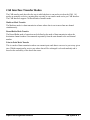
Introduction
Overview of the manual
CAB System
Describes the concepts behind the CAB and how it can be applied within imaging
applications.
Sapera CAB Module API
Describes the additional Sapera API required to control the CAB
Typical CAB Configurations
Demonstrates typical board and mode configuration CAB systems with related code
examples.
Coreco Imaging Contact Information
Contact, sales, and support information.
Appendix: Dummy Buffer Type
Describes the concept of dummy buffers and how they can be applied.
About the Manual
This manual exists in printed, Windows compiled HTML help, and Adobe Acrobat (PDF) formats.
The Help and PDF formats make full use of hypertext cross-references. The PDF format offers links to
Coreco Imaging’s home page on the Internet located at http://www.imaging.com.
Coreco Imaging’s web site contains documents, software updates, demos, errata, utilities, and more.
Using the Manual
File names, directories, and Internet sites will be in bold text (e.g., setup.exe, c:\windows,
http://www.imaging.com). Function parameters will be in italics (e.g., xlen).
Source code, code examples, text file listings, and text that must be entered using the keyboard will be
in typewriter-style text (e.g., [PixelClock]).
Menu and dialog actions will be indicated in bold text in the order of the instructions to be executed,
with each instruction separated by bullets. For example, going to the File menu and choosing Save
would be written as File•Save.
Sapera CAB Programmer's Manual
Introduction • 1
Sapera CAB Programmer's Manual
Introduction • 2
CAB System
CAB Interface
The Coreco Auxiliary Bus (CAB) is a bi-directional synchronous bus capable of transmitting data at a
peak rate of 200MB/sec. CAB is required to meet the increasing bandwidth requirement of embedded
vision processing applications and to free up the PCI bus for system management and control. For
these reasons, all the new generation Coreco Imaging embedded vision processor boards are equipped
with the CAB interface.
A CAB system consists of two or more hardware devices containing CAB interfaces.
CAB System's Functional Elements
The CAB system consists of the following functional elements:
• Bus Arbitrator
• Ports
• Channels
• Clock Generator
• CAB Interface Transfer Modes
Sapera CAB Programmer's Manual
CAB System • 3
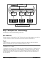
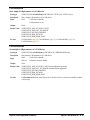
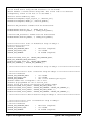
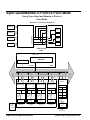
Bus Arbitrator
CLOCK
GENERATOR
Data
Control
32 bits Data Path
Receive Port
#1
Transmit Port
Control
Channel
ID(s)
Acquisition
Device
Frame
Buffer
Receive Port #2
Image Data
Other
CAB
System
Frame
Buffer
Other
CAB
System
Frame
Buffer
Data
Destination(s)
Data Source(s)
Receive
Port #N
Control Channel
Registers ID(s)
Image Data
Channel
Registers ID(s)
Image Data
Control
Registers
Other
CAB
System
Data
Destination(s)
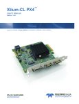
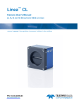
CAB Functional Block Diagram
Key Concepts and Terminology
The following are concepts and terminology of the CAB.
Bus Arbitrator
The Bus Arbitrator is a functional unit of the CAB system that controls and manages access to the bus.
The Bus Arbitrator also decides when and how much data is transferred through the bus.
Ports
A port is defined as a point where the image data is transferred to and taken off from the data bus.
There are essentially two types of ports: a transmit port and a receive port.
Transmit Port (TX Port)
A transmit port is a point in the CAB system where data is transferred onto the bus. A hardware device
containing one or more transmit ports is called a transmitter. A transmitter can have up to 8 physical
transmit ports at the same time. However, the CAB hardware specifications dictate that there can be
only one transmitter in the CAB system at any given time. Furthermore, only one transmit port at a
time can send data.
Sapera CAB Programmer's Manual
CAB System • 4
Receive Port (RX Port)
The receive port is defined as a point in the CAB system where data is taken off the bus. A hardware
device containing the receive port is called a receiver. A receiver can have up to 8 receive ports.
Multiple receive ports on multiple receivers can receive data simultaneously.
It is important to note that in order to direct data to a receive port correctly users must assign a channel
number(s) to a receive port. The bus arbitrator selects the appropriate receive port(s) based on the
channel numbers. The concept of channels is discussed in more detail in a later section.
Through Port
In a typical CAB system the receivers also act as processing nodes. Having more receivers means
having more processing power. Some hardware devices, like Mamba-100, contain multiple CAB
interfaces. The different CAB interfaces allow a hardware device to be part of different CAB systems.
This way one CAB interface can act like a receiver in one CAB system and the second CAB interface
can be configured as a transmitter in another CAB system. In other words, two CAB systems can be
cascaded to increase the total number of receivers in a given system.
In order to cascade two CAB systems, a receive port is configured in such a way that it sends data to
the transmit port of second CAB system located on the hardware device. This type of port is called a
through port. Only one receive port on the Receiver can be configured as a through port.
Channels
Channels are required to direct the data flow from a TX port to an RX port. There are 16 channels in
every CAB system and are identified as channel 0 through channel 15. The channel numbers are
assigned to each transmit and receive port during the parameter initialization. Once a channel number
is assigned to a TX port, that same number must be assigned to at least one RX port.
In addition, the following points must be considered:
• For Multicast and Point-to-Point transmission modes (discussed later), multiple channel
numbers can be assigned to a single receive port.
• The TX ports can also be assigned multiple channels, although seldom necessary.
• For the Point-to-Point transmission mode, only one channel should be assigned to one TX
port.
Clock Generator
The synchronous nature of CAB devices implies the existence of a common clock for the bus
arbitrator, transmit port, and receive ports. The clock generator can be located either on the device
containing the bus arbitrator, the transmit port, or the receive port.
Sapera CAB Programmer's Manual
CAB System • 5
CAB Interface Transfer Modes
The CAB transfer mode describes the way in which the data is sent and received on the CAB. All
modes are mutually exclusive, meaning there can only be one transfer mode active per CAB Interface.
The CAB Interface supports 3 different kinds of transfer mode.
Multicast Mode Transfer
The Multicast mode is a data transmission scheme where data is sent to more than one channel
simultaneously.
Round-Robin Mode Transfer
The Round-Robin mode of operation can be defined as the mode of data transmission where the
destination channel number is incremented sequentially from the start channel to the end channel
number.
Point-to-Point Mode Transfer
This is a mode of data transmission where one transmit port sends data to one receive port at any given
time. Which transmit and/or receive port where data will be exchanged is selected randomly and is
based on the availability of the data at the source.
Sapera CAB Programmer's Manual
CAB System • 6
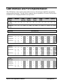
CAB Interface and Port Implementation
The CAB Interface can be used in various modes; however, the actual port capabilities are hardware
implementation dependent. The table below summaries the port capabilities of various CAB Interfaces
on different Coreco Imaging embedded vision processors.
Board
Type
Mamba
Viper
CamLink
Viper
Digital
Viper
Quad
Viper
RGB
Cobra
Python
CAB
Interface
0
1
0
1
0
1
0
1
0
1
0
1
0
1
Number of
ports
4
4
1
N/A
1
N/A
4
N/A
1
N/A
1
N/A
4
N/A
Capability
Port Index(ices)
Transmit
Multicast
0
0
0
x
0
x
0
x
0
x
0
x
x
x
Round-robin
0
0
0
x
0
x
0
x
0
x
0
x
x
x
Point2Point
0,1
2,3
0,1
2,3
x
x
x
x
0,1
2,3
x
x
x
x
x
x
x
Receive
Multicast
0
0
x
x
x
x
x
x
x
x
x
x
Round-robin
0,1
2,3
0,1
2,3
x
x
x
x
x
x
x
x
0,1
2,3
x
Point2Point
0,1
2,3
0,1
2,3
x
x
x
x
x
x
x
x
0,1
2,3
x
PassThrough
Multicast
0
0
x
x
x
x
x
x
x
x
x
x
x
Round-robin
0
0
x
x
x
x
x
x
x
x
x
x
x
Point2Point
0,1
2,3
0,1
2,3
x
x
x
x
x
x
x
x
x
x
x
Sapera CAB Programmer's Manual
CAB System • 7
Clock/Arbitration Capabilities
CAB Clock
Drv/
Rcv
CA
B
Lin
k
Rcv
x
Rcv
x
Rcv
x
Drv
x
Drv
Drv/
Rcv
x
CAB
Arbitrator
En/
Dis
Aut
o
x
x
x
x
x
x
x
x
x
En/
Dis
x
Table Keys
Drv = Able to generate CAB Clock
Rcv = Able to receive CAB Clock from other device
CAB Link = CAB Link hardware provides Clock for Mamba-100 CAB Interface 1
En/Dis = CAB Arbitrator can be Enabled or Disabled
Auto = CAB Link hardware slot position 1 defines Mamba-100 CAB Interface 1 arbitrator
x = Not supported
N/A = Not applicable
Port Indices range from Index 0 through Index 3
Sapera CAB Programmer's Manual
CAB System • 8
Configuring a CAB System
The process of configuring a CAB System can be divided into the following phases:
1.
Pre-power-up static configuration
Configuration steps required before installing into the host computer.
2.
Post-power-up static configuration
Configuration of setup parameters in non-volatile memory.
3.
Post-power-up dynamic configuration
Configuration sequences required in a Sapera application.
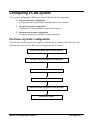
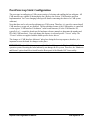
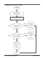
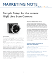
Pre-Power-up Static Configuration
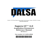
The flow chart and descriptions below suggest a methodology for planning your CAB system. By
following these steps closely CAB system rearrangements will be avoided.
Determine and Sketch CAB connection topology
Record the S/N of each board in the CAB system
Set Jumper for the Clock
Install Boards in the PCI slots
Install cables/CAB-LINK Module to CAB interfaces
Power-up the system
Sapera CAB Programmer's Manual
CAB System • 9
Step 1 Determine and Sketch CAB connection topology
As part of the system design, users should determine and sketch how various hardware devices
containing CAB interfaces will be connected. In order to facilitate this process, several typical
configuration diagrams are provided in the Appendix at the end of this document.
Step 2 Record the serial number of each board in the CAB system
When configuring systems consisting two or more similar CAB devices, it is desirable to relate
physical devices with the device names detected by the software. By recording the serial number of the
device in a system, users can simplify the identification process. All Coreco Imaging Sapera compliant
devices provide device configuration utilities to detect and display the device serial number.
Step 3 Set jumper for the Clock
On some of the Coreco Imaging hardware devices containing a CAB interface, the clock selection is
done manually using a jumper setting. Since only one device can supply the clock for the entire CAB
system, the clock jumper must be disabled for all other devices in the CAB system. It is, however,
important to note that devices containing two CAB interfaces contain two clock sources. Since two
CAB interfaces on the same device participate in two separate CAB systems the clock setting for each
CAB system is made independently. Refer to the section “CAB Interface and Port Implementation” for
specific details concerning the choice of CAB system clock sources relative to the Coreco Imaging
hardware used.
Step 4 Install the boards into system
Install the boards in the system as per the topology determined in Step 1 above.
Step 5 Install cables/CAB-LINK module to the CAB interfaces
Once the boards are installed in the system, connect the cables to the appropriate connectors. Refer to
the hardware specific user’s manual.
Step 6 Power-up the system
Sapera CAB Programmer's Manual
CAB System • 10
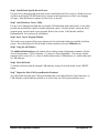
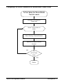
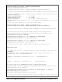
Post-Power-up Static Configuration
The next stage in configuring a CAB system consists of selecting and enabling the bus arbitrator. All
CAB interfaces are capable of arbitrating the bus. (Refer to the section “CAB Interface and Port
Implementation” for Coreco Imaging board specific details concerning the choice of a CAB system
arbitrator).
Note that there can be only one bus arbitrator per CAB system. Therefore, it is crucial to ensure that all
CAB interfaces, except one, are disabled. The bus arbitrator feature of the CAB interface is controlled
via the register “CAB Interface N Arbitrator” in the board firmware (N is the CAB Interface ID,
typically 0 or 1...consult the board specific hardware reference manuals to determine the number and
ID of the CAB Interfaces). Users can change this feature via a board specific “Viewer” utility. The
“Viewer” utilities are supplied with the board specific device drivers.
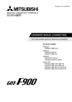
The changes to “CAB Interface Arbitrator” take place during the boot-up sequence; therefore, it is
important to reset the board for changes to take place.
IMPORTANT: embedded vision processors, like Mamba-100, run on the Windows NT Embedded
operation system. Resetting the board arbitrarily can damage the file system. Therefore, the “Shutdown
and Restart” option should be selected from the Reset panel of the Mamba-100 Viewer utility.
Sapera CAB Programmer's Manual
CAB System • 11
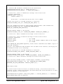
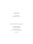
START
Select board specific tab from the m ain window
Select "Main Info" tab from the board window
Install Board specific device drivers
Start hardware "Viewer" utility
*
Scroll down to param eter labeled
"CAB Interface N Arbitrator"
Is the Bus Arbitrator selected and enabled?
No
Yes
set "CAB Interface N* Arbitrator"
to 1 to enable Bus Arbitration
set "CAB Interface N Arbitrator"
**
to 0 to disable
Click on the "Reset" button**
Repeat for every board in the system
End
* N is the CAB Interface ID. Typically 0 or 1.
Consult board specific Hardware reference Manual to determ ine num ber and identify of the CAB Interfaces.
** In case of Mam ba click on the "Reset" button and then select "Shutdown and Restart"
Sapera CAB Programmer's Manual
CAB System • 12
Step 1 Install Board Specific Device Drivers
For each Coreco Imaging board in the host system, install that board’s device driver. Board drivers are
available on the Sapera CD-ROM and also by internet in the download area of the Coreco Imaging
web page. Note that the host computer will need to be re-booted.
Step 2 Start Hardware Viewer Utility
For any Coreco Imaging board that has a selectable CAB arbitration mode, that board’s viewer utility
provides the mechanism to enable or disable arbitration control. From the board’s start menu driver
program group, run the boards viewer program. Refer to the section “CAB Interface and Port
Implementation” for board specific information.
Step 3 and 4 Viewer Program Window
The board viewer program will present a primary tab for each board of that type installed in the host
system. Select the primary tab for the board of interest and then select the Main Info tab.
Step 5 Using the edit Window
The Additional Information scroll window allows editing certain configuration parameters. Double
click on the parameter “CAB n Arbitrator : 0” (where n is board dependent). You can now edit the
parameter with a value of 0 or 1, where 0 disables that board as CAB arbitrator or 1 enables that board
as CAB arbitrator.
Step 6 Reset the Board
To initialize the board with the changed CAB arbitrator setting, click on the board viewer's RESET
button.
Step 7 Repeat for Each CAB System Board as Required.
Any other board using the same CAB system and having a selectable arbitrator control must have its
CAB arbitrator control enabled or disable so as to have only one CAB system arbitrator active.
Sapera CAB Programmer's Manual
CAB System • 13
Post-Power-up Dynamic configuration
Once the connection topology is selected and the pre and post power-up static configurations are done,
the CAB Interfaces must be selected and configured as the transmitter and receivers. This
configuration step is made via software control and does not require rebooting or resetting the
hardware.
This dynamic configuration is performed by the user using Sapera commands. The section labeled
“Putting It All Together” shows skeleton code using Sapera commands to perform dynamic
configurations. The following flow-diagrams outline the configuration steps required to configure the
CAB transmitter and receivers.
It is important to mention that the parameters required to configure the CAB system bus arbitrator
automatically are extracted from the transmitter settings. Users need not configure the CAB system bus
arbitrator explicitly.
Sapera CAB Programmer's Manual
CAB System • 14
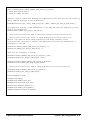
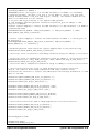
Configuring the CAB System Transmitter
Start
Set TXPHnd =
CAB Interface x
Set Transfer Mode
YES
Configure
Is Transfer Mode =
Tx Ports for
Multicast
Multicast
NO
YES
Configure
Is Transfer Mode =
Tx Ports for
Round Robin
Round
Robin
NO
Configure
Tx Ports for
Point to
Point
End
Sapera CAB Programmer's Manual
CAB System • 15
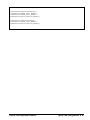
Configuring CAB System Transmitter for Multicast Transfer Mode
Tx Port Setup for Multicast
Transfer m ode
Select Tx Port Index to
setup
Select Channel num ber(s) to be
used by the selected Tx Port
NO
Are
all TX Ports
setup
YES
Return
Sapera CAB Programmer's Manual
CAB System • 16
Configuring CAB System Transmitter for Round-Robin Transfer Mode
Tx Port Setup for Round Robin
Transfer m ode
Set Block Size equal to
Fram e size
Select Tx Port Index to
setup
Select Starting Channel Num ber
Select the Ending Channel
Num ber
NO
Are
all TX Ports
setup
YES
Return
Sapera CAB Programmer's Manual
CAB System • 17
Configuring CAB System Transmitter for Point-To-Point Transfer Mode
Tx Port Setup for
Point2Point Transfer m ode
Select Tx Port Index
to setup
Assign Channel num ber to
Tx Port
NO
Are
all TX Ports
setup
YES
Return
Sapera CAB Programmer's Manual
CAB System • 18
Configuring CAB System Receiver(s)
A CAB System can have one or more receiver. Regardless of the transmission mode, each receive port
in the system is configured for one or more channels. The transmission data block size and end of
block transfers are controlled by the CAB System's bus arbitrator. The Sapera commands and
parameters required to configure the receiver(s) are shown in skeleton code in the next section. The
following flow-diagram outlines steps required to configure one or more CAB receivers in the system:
Start
Set Rcount = Number of
Receivers in the CAB System
Select First Receiver in the
CAB System
Set RPcount = Number of
Rx Ports on Receiver
Select First Rx Port Index
Select next
Receiver in the
CAB System
Assign channel number(s) to
the port
Select next
Rx Port Index
Decrement RPcount by 1
Is
RPcount = 0
NO
YES
Decrement Rcount by 1
NO
Is
Rcount = 0
YES
End
Sapera CAB Programmer's Manual
CAB System • 19
Putting It All Together
What we have seen so far:
1.
Description of CAB system architecture.
2.
Descriptions and definition of CAB terminology.
3.
Determining the CAB usage topology and connection diagrams.
4.
Description of transmit and receive port capabilities as applicable to various hardware
implementation (See table: CAB Interface and Port Implementation).
5.
Steps required to configure a CAB system.
What we will see in the section:
1.
Physical view of various hardware configurations.
2.
CAB System view of the above hardware configurations.
3.
Sapera skeleton code to implement the above configurations.
Sapera CAB Programmer's Manual
CAB System • 20
Sapera CAB Module API
CAB Module
The CAB Module controls the Coreco Auxiliary Bus (CAB) and its functions.
Refer to the section “CAB System” (page 3) for a detailed discussion about CAB concepts.
Capabilities
ID
Parameter
0x00
CORCAB_CAP_PORT
0x01
CORCAB_CAP_PORT_COUNT
0x02
CORCAB_CAP_CHANNEL_COUNT
0x03
CORCAB_CAP_CLK_MIN
0x04
CORCAB_CAP_CLK_MAX
0x05
CORCAB_CAP_BLOCK_SIZE_MIN
0x06
CORCAB_CAP_BLOCK_SIZE_MAX
CORCAB_CAP_BLOCK_SIZE_MAX
Description
Specifies the maximum data block size (in bytes) that a CAB transmitter can send to the CAB
system.
Type
UINT32
CORCAB_CAP_BLOCK_SIZE_MIN
Description
Specifies the minimum data block size (in bytes) that a CAB transmitter can send to the CAB
system.
Type
UINT32
CORCAB_CAP_CHANNEL_COUNT
Description
Indicates the total number of channels available to the CAB system.
Type
UINT32
Sapera CAB Programmer's Manual
Sapera CAB Module API • 21
CORCAB_CAP_CLK_MAX
Description
Specifies the maximum CAB clock frequency (in MHz) that the CAB device can generate.
Type
UINT32
CORCAB_CAP_CLK_MIN
Description
Specifies the minimum CAB clock frequency (in MHz) that the CAB device can generate.
Type
UINT32
CORCAB_CAP_PORT
Description
Indicates the currently selected port's capability to support the different transfer modes. To
select a port, use the parameter CORCAB_PRM_PORT_INDEX.
Type
UINT32
Values
CORCAB_VAL_PORT_MULTICAST_RX (0x00000001)
The port supports multicast transfers as a receive port.
CORCAB_VAL_PORT_MULTICAST_TX (0x00000002)
The port supports multicast transfers as a transmit port.
CORCAB_VAL_PORT_MULTICAST_THROUGH (0x00000004)
The port supports multicast transfers as a through port.
CORCAB_VAL_PORT_MULTICAST (0x0000000f)
The port supports multicast transfers as a transmit, receive, and/or through port.
CORCAB_VAL_PORT_ROUND_ROBIN_RX (0x00000010)
The port supports round robin transfers as a receive port.
CORCAB_VAL_PORT_ROUND_ROBIN_TX (0x00000020)
The port supports round robin transfers as a transmit port.
CORCAB_VAL_PORT_ROUND_ROBIN_THROUGH (0x00000040)
The port supports round robin transfers as a through port.
CORCAB_VAL_PORT_ROUND_ROBIN (0x000000f0)
The port supports round robin transfers as a transmit, receive, and/or through port.
CORCAB_VAL_PORT_POINT_TO_POINT_RX (0x00000100)
The port supports point-to-point transfers as a receive port.
CORCAB_VAL_PORT_POINT_TO_POINT_TX (0x00000200)
The port supports point-to-point transfers as a transmit port.
CORCAB_VAL_PORT_POINT_TO_POINT_THROUGH (0x00000400)
The port supports point-to-point transfers as a through port.
CORCAB_VAL_PORT_POINT_TO_POINT (0x00000f00)
The port supports point-to-point transfers as a transmit, receive, and/or through port.
CORCAB_VAL_PORT_RX (0x00000111)
The port can be a receive port from the CAB system using one of the available transfer modes.
CORCAB_VAL_PORT_TX (0x00000222)
The port can be a transmit port on the CAB system using one of the available transfer modes.
Sapera CAB Programmer's Manual
Sapera CAB Module API • 22
CORCAB_VAL_PORT_THROUGH (0x00000444)
The port can receive and transmit from one CAB system to another using one of the available
transfer modes.
The returned value is the ORed combination of the valid values.
Note
CORCAB_CAP_PORT_COUNT
Description
Indicates the total number of ports available on the CAB device.
Type
UINT32
Parameters
ID
Parameter
0x00
CORCAB_PRM_TRANSFER_MODE
0x01
* CORCAB_PRM_DST_CHANNEL
0x02
* CORCAB_PRM_DST_CHANNEL_FIRST
0x03
* CORCAB_PRM_DST_CHANNEL_LAST
0x04
CORCAB_PRM_BLOCK_SIZE
0x05
CORCAB_PRM_LABEL
0x06
*CORCAB_PRM_CAB_ID
0x07
CORCAB_PRM_CAB_ARBITRATOR
0x08
CORCAB_PRM_CAB_CLK
0x09
*CORCAB_PRM_SRC_CHANNEL_FIRST
0x0a
*CORCAB_PRM_SRC_CHANNEL_LAST
0x0b
CORCAB_PRM_CAB_CLK_GENERATOR
0x0c
CORCAB_PRM_STATUS
0x0d
CORCAB_PRM_CHANNEL
0x0e
CORCAB_PRM_CONNECTION_SIGNAL
0x0f
CORCAB_PRM_PORT_INDEX
*
Obsolete parameters
Sapera CAB Programmer's Manual
Sapera CAB Module API • 23
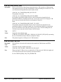
CORCAB_PRM_BLOCK_SIZE
Description
The size of the blocks of data (in bytes) transmitted to the CAB system by a CAB transmitter.
This parameter must be set by the CAB transmitter. It has no meaning for a CAB receiver. The
size of the block will depend on the transfer mode selected:
CORCAB_VAL_TRANSFER_MODE_MULTICAST:
The parameter is not used.
CORCAB_VAL_TRANSFER_MODE_ROUND_ROBIN:
the parameter represents the number of bytes sent to a transmission channel before the
transmission channel is switched to the next one. If one wants to process one image per CAB
device, then one would set the block size to the number of bytes in a
frame.
CORCAB_VAL_TRANSFER_MODE_POINT_TO_POINT:
The parameter represents the number of bytes sent to a transmission channel before the
transmission channel is switched to another one. On a transmit port hooked to an acquisition
device, this parameter can be read-only. In this case, the value is valid for reading once the
CAB device gets connected with the function CorXferConnect.
Type
UINT32
Values
Numerical value within the range
[CORCAB_CAP_BLOCK_SIZE_MIN...CORCAB_CAP_BLOCK_SIZE_MAX] representing
the size of each block (in bytes). Must be a multiple of 4 bytes.
Note
This parameter applies to all the ports of a CAB transmitter.
CORCAB_PRM_CAB_CLK
Description
The CAB clock is the main clock on the bus that controls the CAB arbitrator and FIFOs.
Type
UINT32
Values
CAB clock frequency in MHz in the range:
CORCAB_CAP_CLK_MIN...CORCAB_CAP_CLK_MAX
Note
When more than 2 CAB receivers are connected to a CAB system, the CAB clock might need
to be slowed down to take into account the extra load on the bus.
See also CORCAB_PRM_CAB_CLK_GENERATOR
Sapera CAB Programmer's Manual
Sapera CAB Module API • 24
CORCAB_PRM_CAB_CLK_GENERATOR
Description
This parameter indicates if the CAB device generates the CAB clock. The CAB clock is the
one that controls the flow of data for a CAB system. Only one CAB device can be the clock
generator.
Type
UINT32
Values
TRUE
The CAB device generates the CAB clock.
FALSE
The CAB device does not generate the CAB clock. Another CAB device is the CAB clock
generator.
Note
On some boards, this parameter cannot be programmed and/or detected. See the specific
board’s user's manual for more information about the CAB clock generator.
See also CORCAB_PRM_CAB_CLK
CORCAB_PRM_CAB_ID
Description
This parameter is obsolete. Use the parameter CORCAB_PRM_CHANNEL.
CORCAB_PRM_CAB_ARBITRATOR
Description
This parameter indicates if the CAB device is the CAB arbitrator. The CAB arbitrator is the
one that controls the CAB system. Only one CAB device can be the CAB arbitrator.
Type
UINT32
Values
TRUE
The CAB device is the arbitrator on the CAB system.
FALSE
The CAB device is not the arbitrator on the CAB system.
Note
On some boards, this parameter cannot be programmed. See the specific board’s user's manual
for more information about setting the board as the CAB arbitrator.
Sapera CAB Programmer's Manual
Sapera CAB Module API • 25
CORCAB_PRM_CHANNEL
Description
Transmit or receiving channel(s) associated with the currently selected port. To select a port,
use the parameter CORCAB_PRM_PORT_INDEX.
Refer to the section “Channels” on page 5 for a more detailed description concerning the
concept of channels.
Type
UINT32
Values
CORCAB_VAL_CHANNEL_0 (0x00000001)
CAB Channel 0
CORCAB_VAL_CHANNEL_1 (0x00000002)
CAB Channel 1
CORCAB_VAL_CHANNEL_2 (0x00000004)
CAB Channel 2
CORCAB_VAL_CHANNEL_3 (0x00000008)
CAB Channel 3
CORCAB_VAL_CHANNEL_4 (0x00000010)
CAB Channel 4
CORCAB_VAL_CHANNEL_5 (0x00000020)
CAB Channel 5
CORCAB_VAL_CHANNEL_6 (0x00000040)
CAB Channel 6
CORCAB_VAL_CHANNEL_7(0x00000080)
CAB Channel 7
CORCAB_VAL_CHANNEL_8 (0x00000100)
CAB Channel 8
CORCAB_VAL_CHANNEL_9 (0x00000200)
CAB Channel 9
CORCAB_VAL_CHANNEL_10 (0x00000400)
CAB Channel 10
CORCAB_VAL_CHANNEL_11 (0x00000800)
CAB Channel 11
CORCAB_VAL_CHANNEL_12 (0x00001000)
CAB Channel 12
CORCAB_VAL_CHANNEL_13 (0x00002000)
CAB Channel 13
CORCAB_VAL_CHANNEL_14(0x00004000)
CAB Channel 14
CORCAB_VAL_CHANNEL_15 (0x00008000)
CAB Channel 15
Note
The values may be ORed if more than one channel is desired.
Sapera CAB Programmer's Manual
Sapera CAB Module API • 26
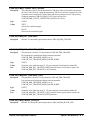
CORCAB_PRM_CONNECTION_SIGNAL
Description
The connection signal is used to determine the CAB devices that are physically connected to
the same CAB system. By setting this parameter to TRUE, one activates a signal on the CAB
system that can be monitored by all the other CAB devices connected to the CAB system by
reading the parameter CORCAB_PRM_STATUS and verifying if the
CORCAB_PRM_STATUS_CONNECTION_SIGNAL bit is active.
Type
UINT32
Values
TRUE
Activate the connection signal.
FALSE
Deactivate the connection signal.
CORCAB_PRM_DST_CHANNEL
Description
Obsolete. Use instead the equivalent parameter CORCAB_PRM_CHANNEL
CORCAB_PRM_DST_CHANNEL_FIRST
Description
This parameter is obsolete. Use the parameter CORCAB_PRM_CHANNEL.
First destination or transmission channel when the parameter
CORCAB_PRM_TRANSFER_MODE is set to
CORCAB_VAL_TRANSFER_MODE_ROUND_ROBIN.
Type
UINT32
Values
Numerical value within the range [0...15] representing the first destination channel ID.
Note
CORCAB_PRM_DST_CHANNEL_FIRST parameter must be lower than or equal to the
CORCAB_PRM_DST_CHANNEL_LAST parameter.
CORCAB_PRM_DST_CHANNEL_LAST
Description
This parameter is obsolete. Use the parameter CORCAB_PRM_CHANNEL.
Last destination or transmission channel when the parameter
CORCAB_PRM_TRANSFER_MODE is set to
CORCAB_VAL_TRANSFER_MODE_ROUND_ROBIN.
Type
UINT32
Values
Numerical value within the range [0...15] representing the last destination channel ID.
Note
CORCAB_PRM_DST_CHANNEL_LAST parameter must be greater than or equal to the
CORCAB_PRM_DST_CHANNEL_FIRST parameter.
CORCAB_PRM_FRAME_LENGTH
Description
Obsolete. Use instead the equivalent parameter CORCAB_PRM_BLOCK_SIZE.
Sapera CAB Programmer's Manual
Sapera CAB Module API • 27
CORCAB_PRM_LABEL
Description
The CAB device's string ID.
Type
Zero-terminated array of characters with a fixed size of 128 bytes.
Values
CORCAB_PRM_LABEL is a read-only parameter.
CORCAB_PRM_PORT_INDEX
Description
Specifies the port number that is active. By selecting a new active port, the following
parameters will be updated to reflect the current state of the port:
CORCAB_PRM_CHANNEL and CORCAB_CAP_PORT
Type
UINT32
Values
Active port number: 0 .. CORCAB_CAP_PORT_COUNT- 1
CORCAB_PRM_SRC_CHANNEL_FIRST
Description
This parameter is obsolete. Use the parameter CORCAB_PRM_CHANNEL.
First source or receiving channel when the parameter CORCAB_PRM_TRANSFER_MODE
is set to CORCAB_VAL_TRANSFER_MODE_ROUND_ROBIN.
Type
UINT32
Values
Numerical value within the range [0...15] representing the first source channel ID.
Note
This parameter must be lower than or equal to the parameter
CORCAB_PRM_SRC_CHANNEL_LAST.
CORCAB_PRM_SRC_CHANNEL_LAST
Description
This parameter is obsolete. Use the parameter CORCAB_PRM_CHANNEL.
Last source or receiving channel when the parameter CORCAB_PRM_TRANSFER_MODE is
set to CORCAB_VAL_TRANSFER_MODE_ROUND_ROBIN.
Type
UINT32
Values
Numerical value within the range [0...15] representing the last source channel ID.
Note
This parameter must be greater than or equal to the parameter
CORCAB_PRM_SRC_CHANNEL_FIRST.
Sapera CAB Programmer's Manual
Sapera CAB Module API • 28
CORCAB_PRM_STATUS
Description
Returns information about the current status of the CAB system.
Type
UINT32
Values
CORCAB_VAL_STATUS_GRANTED (0x00000001)
The CAB system is considered GRANTED if a CAB transmitter has been granted
transmission rights to the CAB system by the CAB arbitrator. Only one CAB transmitter can
be granted permission to transmit to the CAB system. Once the CAB system is granted, no
CAB parameters can be changed. The CAB system is granted to a CAB transmitter once it is
connected using the function CorXferConnect, the CAB transmitter being one of the
destination pair(s) of the transfer module.
CORCAB_VAL_STATUS_CONNECTION_SIGNAL (0x00000002)
The connection signal bit is active if a CAB device connected to the CAB system has activated
the signal using the parameter CORCAB_PRM_CONNECTION_SIGNAL. The connection
signal status is useful in determining which CAB devices are connected to a CAB system
when multiple CAB systems are present in a system.
Note
The returned value is the ORed combination of the valid values.
This parameter is read-only.
CORCAB_PRM_TRANS_MODE
Description
Obsolete. Use instead the equivalent parameter CORCAB_PRM_TRANSFER_MODE
CORCAB_PRM_TRANSFER_MODE
Description
Controls CAB system data routing. This parameter must be set by the CAB transmitter. It has
no meaning for a CAB receiver.
Type
UINT32
Values
CORCAB_VAL_TRANSFER_MODE_MULTICAST (0x00000000)
One source to one or more simultaneous destinations
CORCAB_VAL_TRANSFER_MODE_ROUND_ROBIN (0x00000001)
One source to 2 or more destinations in round robin fashion
CORCAB_VAL_TRANSFER_MODE_POINT_TO_POINT (0x00000010)
Multiple sources, each going to a single destination.
Note
This parameter applies to all the ports of a CAB transmitter.
Refer to the CAB User’s manual for more information about the different types of transfer
mode.
Sapera CAB Programmer's Manual
Sapera CAB Module API • 29
Functions
Function
Description
CorCabGetCap
Gets CAB capability value from a CAB device
CorCabGetCount
Gets the number of CAB devices on a server
CorCabGetHandle
Gets a handle to a CAB device
CorCabGetPrm
Gets CAB parameter value from a CAB device
CorCabGetPrms
Gets multiple CAB parameters from a CAB device
CorCabRelease
Releases handle to a CAB device
CorCabReset
Resets a CAB device
CorCabResetModule
Resets the resources associated with the server’s CAB device(s)
CorCabSetPrm
Sets a simple CAB parameter of a CAB device
CorCabSetPrms
Sets multiple CAB parameters of a CAB device
CorCabSetPrmEx
Sets a complex CAB parameter of a CAB device
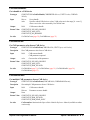
CorCabGetCap
Get CAB capability value from a CAB device
Prototype
CORSTATUS CorCabGetCap(CORCAB hCab, UINT32 cap, void *value);
Description
Gets CAB capability value from a CAB device.
Input
hCab
CAB device handle
cap
The CAB device capability requested
Output
value
Value of the capability
Return Value
CORSTATUS_INVALID_HANDLE
CORSTATUS_CAP_INVALID
CORSTATUS_ARG_NULL ( if value is NULL)
CorCabGetCount
Get the number of CAB devices on a server
Prototype
CORSTATUS CorCabGetCount(CORSERVER hServer, UINT32 *count);
Description
Gets the number of CAB devices on a server.
Input
hServer
Server handle
Output
count
Number of CAB devices
Return Value
CORSTATUS_INVALID_HANDLE
CORSTATUS_ARG_NULL ( if count is NULL)
Note
The content of count is 0 when there is no CAB device available.
Sapera CAB Programmer's Manual
Sapera CAB Module API • 30
CorCabGetHandle
Get a handle to a CAB device
Prototype
CORSTATUS CorCabGetHandle(CORSERVER hServer, UINT32 index, CORCAB
*hCab);
Input
hServer
Server handle
index
Specifies which CAB device to select. Valid values are in the range [0...count-1],
where count is the value returned by CorCabGetCount.
Output
hCab
CAB resource handle
Return Value
CORSTATUS_INVALID_HANDLE
CORSTATUS_ARG_NULL
CORSTATUS_NO_MEMORY
See Also
CorCabGetCount (page 30), CorCabRelease (page 32)
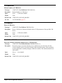
CorCabGetPrm
Get CAB parameter value from a CAB device
Prototype
CORSTATUS CorCabGetPrm(CORCAB hCab, UINT32 prm, void *value);
Description
Gets CAB parameter value from a CAB device.
Input
hCab
CAB resource handle
CAB parameter requested
Output
value
Return Value
CORSTATUS_INVALID_HANDLE
CORSTATUS_ARG_NULL
CORSTATUS_PRM_INVALID
Current value of the parameter
See Also
CorCabSetPrm (page 33), CorCabGetPrms (page 31), CorCabSetPrmEx (page 34),
CorCabSetPrms (page 33)
CorCabGetPrms
Get multiple CAB parameters from a CAB device
Prototype
CORSTATUS CorCabGetPrms(CORCAB hCab, CORPARAM hParam);
Description
Gets multiple CAB parameters from a CAB device.
Input
hCab
CAB resource handle
hParam
Parameters resource handle
Output
None
Return Value
CORSTATUS_INVALID_HANDLE
CORSTATUS_PRM_INVALID
CORSTATUS_PRM_READ_ONLY
See Also
CorParamSave function in the Sapera Basic Modules Reference Manual (available as online
version only)
Sapera CAB Programmer's Manual
Sapera CAB Module API • 31
CorCabRelease
Release handle to a CAB device
Prototype
CORSTATUS CorCabRelease(CORCAB hCab);
Description
Releases handle to a CAB device.
Input
hCab
Output
None
Return Value
CORSTATUS_INVALID_HANDLE
See Also
CorCabGetHandle (page 31)
CAB resource handle
CorCabReset
Reset a CAB device
Prototype
CORSTATUS CorCabReset(CORCAB hCab);
Description
Resets a CAB device. Restores the default values of CAB parameters of the specified CAB
device.
Input
hCab
Output
None
Return Value
CORSTATUS_INVALID_HANDLE
CAB resource handle
CorCabResetModule
Reset the resources associated with the server’s CAB device(s)
Prototype
CORSTATUS CorCabResetModule(CORSERVER hServer);
Description
Resets the resources associated with the server’s CAB device(s). It will release all of the
resources (handle, memory) currently allocated. When using this function, make certain that
no other application is currently using any CAB device resource. This function should be use
with caution.
Input
hServer
Output
None
Return Value
CORSTATUS_INVALID_HANDLE
Server handle
Sapera CAB Programmer's Manual
Sapera CAB Module API • 32
CorCabSetPrm
Set a simple CAB parameter of a CAB device
Prototype
CORSTATUS CorCabSetPrm(CORCAB hCab, UINT32 prm, UINT32 value);
Description
Sets a simple CAB parameter of a CAB device.
Input
hCab
Output
None
Return Value
CORSTATUS_ARG_INVALID_VALUE
CORSTATUS_ARG_OUT_OF_RANGE
CORSTATUS_INVALID_HANDLE
CORSTATUS_PRM_INVALID
CORSTATUS_PRM_READ_ONLY
See Also
CorCabGetPrm (page 31), CorCabSetPrms (page 33), CorCabSetPrmEx ( page 34),
CorCabGetPrms (page 31)
CAB resource handle
CAB parameter to set
CorCabSetPrms
Set multiple CAB parameters of a CAB device
Prototype
CORSTATUS CorCabSetPrms (CORCAB hCab, CORPARAM hParam);
Description
Sets multiple CAB parameter of a CAB device.
Input
hCab
CAB resource handle
hParam
Parameters resource handle
Output
None
Return Value
CORSTATUS_ARG_INVALID_VALUE (internal hParam argument)
CORSTATUS_ARG_OUT_OF_RANGE (internal hParam argument)
CORSTATUS_INVALID_HANDLE
CORSTATUS_PRM_INVALID
CORSTATUS_PRM_READ_ONLY
See Also
CorParamLoad function in the Sapera Basic Modules Reference Manual (available as online
version only)
Sapera CAB Programmer's Manual
Sapera CAB Module API • 33
CorCabSetPrmEx
Set a complex CAB parameter of a CAB device
Prototype
CORSTATUS CorCabSetPrmEx(CORCAB hCab, UINT32 prm, const void *value);
Description
Sets a complex CAB parameter of a CAB device.
Input
hCab
CAB resource handle
prm
CAB parameter to set
value
New value of the parameter
Output
None
Return Value
CORSTATUS_ARG_INVALID_VALUE
CORSTATUS_ARG_NULL
CORSTATUS_ARG_OUT_OF_RANGE
CORSTATUS_INVALID_HANDLE
CORSTATUS_PRM_INVALID
CORSTATUS_PRM_READ_ONLY
Note
A complex parameter is one whose size is greater than an UINT32. If the parameter size is
UINT32, either CorCabSetPrm or CorCabSetPrmEx can be used.
See Also
CorCabGetPrm (page 31), CorCabSetPrm (page 33)
Sapera CAB Programmer's Manual
Sapera CAB Module API • 34
Typical CAB Configurations
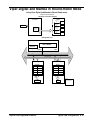
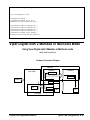
Viper-Digital/Mamba-100 in Multicast Mode
Using Viper Digital and Mamba in Multicast mode
- Single node architecture
Hardware Connection Diagram
Mamba
CAB Interface 1
Viper Digital
FB0
CAB Interface 0
CAB Interface 0
Camera
CAB System View
Viper Digital
Bus Arbitrator
CLOCK
GENERATOR
Data
Control
32 bits Data Path
Viper Digital
Transmitter
Mamba
Receiver
Port 0
8
Port 0
8
Port 1
NA
Port 1
X
Port 2
NA
Port 2
X
Port 3
NA
Port 3
X
Image
Data
Acquisition
Device
Data Source(s)
Sapera CAB Programmer's Manual
Image
Data
Legends
Frame
Buffer
NA = Not Applicable
x = Don't care
Data Destination(s)
Typical CAB Configurations • 35
// Assumes the following physical setup:
//- one Viper-Digital
//- two Mamba-100s
//- Cab interface of Viper is connected to Cab interface 0 of Mamba_1
//- Cab interface 1 of Mamba_1 is connected to Cab interface 1 of Mamba_2
CORSERVER hServer_VD1;
CORSERVER hServer_Mamba1;
CORSERVER hServer_Mamba2;
CORCAB
CORCAB
CORCAB
CORCAB
hCAB_Intf0_VD1;
hCAB_Intf0_Mamba1;
hCAB_Intf1_Mamba1;
hCAB_Intf1_Mamba2;
CORXFER hXfer_VD1_Acq_To_CAB_Intf0;
CORXFER hXfer_Mamba1_CAB_Intf0_To_Buffer0;
CORXFER hXfer_Mamba2_CAB_Intf1_To_Buffer0;
CORBUFFER hBuffer_Mamba1[4];
CORBUFFER hBuffer_Mamba2;
CORXFER_DESC xferDesc;
int main()
{
// Used when transferring from a Mamba-100 Cab interface to a Mamba-100 buffer only
xferDesc.frame = CORXFER_VAL_FRAME_INTERLACED;
xferDesc.fieldOrder = CORXFER_VAL_FIELD_ORDER_ODD_EVEN;
xferDesc.widthByte = 640;
xferDesc.height = 480;
xferDesc.incByte = 640;
// This example shows how to setup Multicast mode of transmission in a single
// CAB system configuration
//Test 1 assumes the following physical setup:
//
- one Viper-Digital
//
- one Mamba-100
//
- Cab interface of Viper is connected to Cab
interface 0 of Mamba-100
//
// Transfer is:
//- multicast mode on Cab interface of Viper
//- one buffer on port 0 of Cab interface 0 of the Mamba-100
SetupTest1();
DoTest1();
CleanupTest1();
}
void SetupTest1(void)
{
//
//
//
//
The following commands assume that the users has reviewed the hardware architecture
of the boards and is using the CAB Interface 0 of the boards.
Obtain handles to Board servers using name. This allows code to be executed
transparently either the host or on the Mamba-100 1
// Retrieve Server handles
CorManGetServerByName("Viper_Digital_1", &hServer_VD1);
Sapera CAB Programmer's Manual
Typical CAB Configurations • 36
CorManGetServerByName("Mamba_1", &hServer_Mamba1);
// retrieve CAB Interface 0 handle from the board server
CorCabGetHandle(hServer_VD1, 0, &hCAB_Intf0_VD1);
CorCabGetHandle(hServer_Mamba1, 0, &hCAB_Intf0_Mamba1);
// ************ Start of Transmitter settings ******************
// Critical Parameters:
//TRANSFER_MODE = Multicast
//
Channel number = 8
//
//
Block Size = For Multicast block size is not needed.
//Select the Tx_Port on the CAB Interface to work with.
CorCabSetPrm(hCAB_Intf0_VD1, CORCAB_PRM_PORT_INDEX, 0);
//Set the transmission mode for Viper digital CAB Interface 0(The Transmitter).
CorCabSetPrm(hCAB_Intf0_VD1, CORCAB_PRM_TRANSFER_MODE,
CORCAB_VAL_TRANSFER_MODE_MULTICAST);
//Assign channel number to the TX_Port
CorCabSetPrm(hCAB_Intf0_VD1, CORCAB_PRM_CHANNEL, CORCAB_VAL_CHANNEL_8);
// ************
End of Transmitter settings ******************
// ************ Start of Receiver settings ***********************
// Critical Parameters:
//Transfer Mode
=
Not needed
//Channel Number
=
One of the channel numbers used for the Tx_port
//Block size
=
Not needed
//
//The CORCAB_CAP_PORT_COUNT capability can be used to determine the number of port on
//the CAB Interface.
//Notice: since Mamba-100 CAB Interface will be used as the receiver, setting up the
//transmission mode is not necessary.
//Select the Rx_Port on the CAB Interface to work with.
CorCabSetPrm(hCAB_Intf0_Mamba1, CORCAB_PRM_PORT_INDEX, 0);
//Assign channel number to the RX_Port
CorCabSetPrm(hCAB_Intf0_Mamba1, CORCAB_PRM_CHANNEL, CORCAB_VAL_CHANNEL_8);
// ************ End of Receiver settings ***********************
//The following command creates a frame buffer in Mamba 1 system memory.
CorBufferNew(hServer_Mamba1, 640, 480, CORBUFFER_VAL_FORMAT_MONO8,
CORBUFFER_VAL_TYPE_CONTIGUOUS, &hBuffer_Mamba1[0]));
}
void DoTest1(void)
{
// ************************* Start of Connection Setup ************************
//Creates logical connections between the frame buffer(the final destination of data)
//and the Rx_ports on the Receiver.
CorXferNewEx(hServer_Mamba1, hCAB_Intf0_Mamba1, 0, hBuffer_Mamba1[0], 0, &xferDesc,
&hXfer_Mamba1_CAB_Intf0_To_Buffer0);
Sapera CAB Programmer's Manual
Typical CAB Configurations • 37
// Sets physical routing of the Receiver to the CAB and from the Receiver to the
buffer CorXferConnect(hXfer_Mamba1_CAB_Intf0_To_Buffer0);
// Final destination where
// receiver sends the data
//Creates logical connections between the acquisition front end (the initial source of
//data) and the Tx_ports on the Transmitter.
CorXferNew(hServer_VD1, hAcq, hCAB_Intf0_VD1, NULL, &hXfer_VD1_Acq_To_CAB_Intf0));
//Sets physical routing of the Transmitter to the CAB and from the acquisition front
//end to the Transmitter.
CorXferConnect(hXfer_VD1_Acq_To_CAB_Intf0);
// ************************* End of Connection Setup ************************
// ************************* Start of Image Acquisition ********************
//Notice: the order in which Image acquisition and image transfer starts.
//Initialize the receivers to receive from CAB before initializing Transmitter to
//send data to the CAB.
CorXferStart(hXfer_Mamba1_CAB_Intf0_To_Buffer0, 1);
CorXferStart(hXfer_VD1_Acq_To_CAB_Intf0, 1);
//wait for the transfers to finish
CorXferWait(hXfer_Mamba1_CAB_Intf0_To_Buffer0, 2000);
CorXferWait(hXfer_VD1_Acq_To_CAB_Intf0, 2000);
CorXferDisconnect(hXfer_Mamba1_CAB_Intf0_To_Buffer0);
CorXferDisconnect(hXfer_VD1_Acq_To_CAB_Intf0);
// ************************* End of Image Acquisition ********************
CorXferFree(hXfer_Mamba1_CAB_Intf0_To_Buffer0);
CorXferFree(hXfer_VD1_Acq_To_CAB_Intf0);
}
void CleanupTest1(void)
{
CorAcqRelease(hAcq);
CorCabRelease(hCAB_Intf0_VD1);
CorManReleaseServer(hServer_VD1);
CorBufferFree(hBuffer_Mamba1[0]);
CorCabRelease(hCAB_Intf0_Mamba1);
CorManReleaseServer(hServer_Mamba1);
}
Sapera CAB Programmer's Manual
Typical CAB Configurations • 38
Viper-Digital and Mamba in Round-Robin Mode
Using Viper Digital and Mamba in Round Robin mode
- Single node architecture
Hardware Connection Diagram
CAB Interface 1
Viper Digital
Camera
CAB Interface 0
CAB Interface 0
Tx_Port 0
(start)Ch8|
(end)Ch11
Mamba
Rx_Port 0
Ch8
FB0
Rx_Port 1
Ch9
FB1
Rx_Port 2
Ch10
FB2
Rx_Port 3
Ch11
FB3
CAB System View
Viper Digital
Bus Arbitrator
CLOCK
GENERATOR
Data
Control
32 bits Data Path
Viper Digital
Transmitter
Mamba
Receiver
Port 0
8
Port 0
Port 1
NA
Port 1
9
Port 2
NA
Port 2
10
Port 3
NA
Port 3
11
Image
Data
8
Image
Data
Legends
Acquisition
Device
Data Source(s)
Sapera CAB Programmer's Manual
Frame
Buffer
NA = Not Applicable
Data Destination(s)
Typical CAB Configurations • 39
// Assumes the following physical setup:
//- one Viper-Digital
//- two Mambas
//- Cab interface of Viper is connected to Cab interface 0 of Mamba_1
//- Cab interface 1 of Mamba_1 is connected to Cab interface 1 of Mamba_2
CORSERVER hServer_VD1;
CORSERVER hServer_Mamba1;
CORSERVER hServer_Mamba2;
CORCAB
CORCAB
CORCAB
CORCAB
hCAB_Intf0_VD1;
hCAB_Intf0_Mamba1;
hCAB_Intf1_Mamba1;
hCAB_Intf1_Mamba2;
CORXFER hXfer_VD1_Acq_To_CAB_Intf0;
CORXFER hXfer_Mamba1_CAB_Intf0_To_Buffer0;
CORXFER hXfer_Mamba2_CAB_Intf1_To_Buffer0;
CORBUFFER hBuffer_Mamba1[4];
CORBUFFER hBuffer_Mamba2;
CORXFER_DESC xferDesc;
int main()
{
// Used when transferring from a Mamba Cab interface to a Mamba buffer only
xferDesc.frame = CORXFER_VAL_FRAME_INTERLACED;
xferDesc.fieldOrder = CORXFER_VAL_FIELD_ORDER_ODD_EVEN;
xferDesc.widthByte = 640;
xferDesc.height = 480;
xferDesc.incByte = 640;
//The next example shows how to setup Round Robin mode of transmission in a single CAB
//system configuration
//Test 2 assumes the following physical setup:
//- one Viper-Digital
//- one Mamba
//- Cab interface of Viper is connected to Cab interface 0 of Mamba
//
// Transfer is:
//- round-robin mode on Cab interface of Viper
//- one buffer on port 0 of Cab interface 0 of the Mamba
//- one buffer on port 1 of Cab interface 0 of the Mamba
//- one buffer on port 2 of Cab interface 0 of the Mamba
//- one buffer on port 3 of Cab interface 0 of the Mamba
SetupTest2();
DoTest2();
CleanupTest2();
return 0;
}
void SetupTest2(void)
{
//The following commands assume that the users has reviewed the hardware architecture
//of the boards and is using the CAB Interface 0 of the boards.
//Obtain handles to Board servers using name. This allows code to be executed
Sapera CAB Programmer's Manual
Typical CAB Configurations • 40
//transparently either on the host or on the Mamba 1
// Retrieve server handles by name
CorManGetServerByName("Viper_Digital_1", &hServer_VD1);
CorManGetServerByName("Mamba_1", &hServer_Mamba1);
// Retrieve CAB_Interface 0 handle on each of the board server
CorCabGetHandle(hServer_VD1, 0, &hCAB_Intf0_VD1);
CorCabGetHandle(hServer_Mamba1, 0, &hCAB_Intf0_Mamba1);
// ********************* Start of Transmitter Setup ***************************
// Critical Parameters
//CORCAB_PRM_TRANSFER_MODE
=
Round Robin (Required)
//CORCAB_PRM_BLOCK_SIZE
=
frame size (required)
//CORCAB_PRM_CHANNEL
=
start and end channels. Channel numbers
//between start and end channel numbers are
//incremented at the end of each transfer.
//
CorCabSetPrm(hCAB_Intf0_VD1, CORCAB_PRM_TRANSFER_MODE,
CORCAB_VAL_TRANSFER_MODE_ROUND_ROBIN);
CorCabSetPrm(hCAB_Intf0_VD1, CORCAB_PRM_BLOCK_SIZE, 640 * 480);
// Start channel
=
8
// End channel
=
11
CorCabSetPrm(hCAB_Intf0_VD1, CORCAB_PRM_CHANNEL,CORCAB_VAL_CHANNEL_8 |
CORCAB_VAL_CHANNEL_11);
// ********************* End of Transmitter Setup ***************************
// ********************* Start of Receiver Setup ***************************
// Critical Parameters
//CORCAB_PRM_TRANSFER_MODE
=
not needed
//CORCAB_PRM_BLOCK_SIZE
=
not needed
//CORCAB_PRM_CHANNEL
=
One or more channels per Rx_Port
//Channel number must correspond to one or more
//channels #s programmed for one or more Tx_Port.
//Select the Rx_port before initializing the Channel number
CorCabSetPrm(hCAB_Intf0_Mamba1, CORCAB_PRM_PORT_INDEX, 0);
CorCabSetPrm(hCAB_Intf0_Mamba1, CORCAB_PRM_CHANNEL, CORCAB_VAL_CHANNEL_8);
CorCabSetPrm(hCAB_Intf0_Mamba1, CORCAB_PRM_PORT_INDEX, 1);
CorCabSetPrm(hCAB_Intf0_Mamba1, CORCAB_PRM_CHANNEL, CORCAB_VAL_CHANNEL_9);
CorCabSetPrm(hCAB_Intf0_Mamba1, CORCAB_PRM_PORT_INDEX, 2);
CorCabSetPrm(hCAB_Intf0_Mamba1, CORCAB_PRM_CHANNEL, CORCAB_VAL_CHANNEL_10);
CorCabSetPrm(hCAB_Intf0_Mamba1, CORCAB_PRM_PORT_INDEX, 3);
CorCabSetPrm(hCAB_Intf0_Mamba1, CORCAB_PRM_CHANNEL, CORCAB_VAL_CHANNEL_11);
// ********************* End of Receiver Setup ***************************
// ******************* Start of Frame buffer allocation ********************
//The following section allocates the frame buffers and stores handles of the
//frame buffer in an array of handles
Sapera CAB Programmer's Manual
Typical CAB Configurations • 41
CorBufferNew(hServer_Mamba1, 640, 480, CORBUFFER_VAL_FORMAT_MONO8,
CORBUFFER_VAL_TYPE_CONTIGUOUS, &hBuffer_Mamba1[0]));
CorBufferNew(hServer_Mamba1, 640, 480, CORBUFFER_VAL_FORMAT_MONO8,
CORBUFFER_VAL_TYPE_CONTIGUOUS, &hBuffer_Mamba1[1]));
CorBufferNew(hServer_Mamba1, 640, 480, CORBUFFER_VAL_FORMAT_MONO8,
CORBUFFER_VAL_TYPE_CONTIGUOUS, &hBuffer_Mamba1[2]));
CorBufferNew(hServer_Mamba1, 640, 480, CORBUFFER_VAL_FORMAT_MONO8,
CORBUFFER_VAL_TYPE_CONTIGUOUS, &hBuffer_Mamba1[3]));
// ******************* End of Frame buffer allocation ********************
}
void DoTest2(void)
{
//************************* Start of Receiver Connection Setup
************************
//Creates logical connections between the frame buffer(the final destination of data)
//and the Rx_ports on the Receiver.
CorXferNewEx(hServer_Mamba1, hCAB_Intf0_Mamba1, 0,
&hXfer_Mamba1_CAB_Intf0_To_Buffer0);
CorXferAppendEx(hXfer_Mamba1_CAB_Intf0_To_Buffer0,
hBuffer_Mamba1[1], 0, &xferDesc));
CorXferAppendEx(hXfer_Mamba1_CAB_Intf0_To_Buffer0,
hBuffer_Mamba1[2], 0, &xferDesc));
CorXferAppendEx(hXfer_Mamba1_CAB_Intf0_To_Buffer0,
hBuffer_Mamba1[3], 0, &xferDesc));
hBuffer_Mamba1[0], 0, &xferDesc,
hCAB_Intf0_Mamba1, 1,
hCAB_Intf0_Mamba1, 2,
hCAB_Intf0_Mamba1, 3,
// Sets physical routing of the Receiver to the CAB and from the Receiver to the
buffer
CorXferConnect(hXfer_Mamba1_CAB_Intf0_To_Buffer0);
//*************** Start of Transmitter Connection Setup ************************
//Creates logical connections between the acquisition front end (the initial source of
//data) and the Tx_ports on the Transmitter.
CorXferNew(hServer_VD1, hAcq, hCAB_Intf0_VD1, NULL, &hXfer_VD1_Acq_To_CAB_Intf0));
//Sets physical routing of the Transmitter to the CAB and from the acquisition front
//end to the Transmitter.
CorXferConnect(hXfer_VD1_Acq_To_CAB_Intf0);
// *********************** End of Transmitter Connection Setup **********************
// ************************* Start of Image Acquisition ********************
//Notice, the order in which Image acquisition and image transfer starts.
//Initialize the receivers to receive from CAB before initializing Transmitter to send
//data to the CAB.
CorXferStart(hXfer_Mamba1_CAB_Intf0_To_Buffer0, 4);
CorXferStart(hXfer_VD1_Acq_To_CAB_Intf0, 4);
CorXferWait(hXfer_Mamba1_CAB_Intf0_To_Buffer0, 2000);
CorXferWait(hXfer_VD1_Acq_To_CAB_Intf0, 2000);
CorXferDisconnect(hXfer_Mamba1_CAB_Intf0_To_Buffer0);
CorXferDisconnect(hXfer_VD1_Acq_To_CAB_Intf0);
// ************************* End of Image Acquisition ********************
CorXferFree(hXfer_Mamba1_CAB_Intf0_To_Buffer0);
Sapera CAB Programmer's Manual
Typical CAB Configurations • 42
CorXferFree(hXfer_VD1_Acq_To_CAB_Intf0);
}
void CleanupTest2(void)
{
CorAcqRelease(hAcq);
CorCabRelease(hCAB_Intf0_VD1);
CorManReleaseServer(hServer_VD1);
CorBufferFree(hBuffer_Mamba1[0]);
CorBufferFree(hBuffer_Mamba1[1]);
CorBufferFree(hBuffer_Mamba1[2]);
CorBufferFree(hBuffer_Mamba1[3]);
CorCabRelease(hCAB_Intf0_Mamba1);
CorManReleaseServer(hServer_Mamba1);
}
Viper-Digital with 2 Mambas in Multicast Mode
Using Viper Digital with 2 Mambas in Multicast mode
Multi-node Architecture
Hardware Connection Diagram
CAB Interface 1
Viper Digital
Mamba # 1
Tx_Port 0 Ch10
CAB Interface 1
CAB Sys1
Mamba #2
Rx_Port 0 Ch 10
Rx_Port 0 Ch8
Rx_Port 0 Ch9
FB0
CAB Interface 0
CAB Interface 0
Tx_Port 0
Ch8,9
CAB Interface 0
Camera
FB0
CAB Sys0
Sapera CAB Programmer's Manual
Typical CAB Configurations • 43
CAB System View
Viper Digital
Bus Arbitrator
CLOCK
GENERATOR
Control
CAB Sys 0
Data
32 bits Data Path
Viper Digital
Mamba #1
Transmitter
Receiver
Port 0
Ch8,9
Port 0
Ch8
Port 1
NA
Port 1
Ch9
Port 2
NA
Port 2
x
Port 3
NA
Port 3
x
Image
Data
Acquisition
Device
Frame
Buffer
To CAB
SYS 1
Data Source(s)
Data Destination(s)
Data Destination(s)
Data Source(s)
Frame
Buffer
CAB Sys 1
From CAB
SYS 0
Image
Data
Image
Data
x
Port 3
x
Port 3
x
Port 2
x
Port 2
x
Port 1
x
Port 1
Ch10
Port 0
Ch10
Port 0
Receiver
Mamba #2
Transmitter
Mamba #1
32 bits Data Path
Data
Bus Arbitrator
Control
CLOCK
GENERATOR
Mamba # 2 CAB Interface 1
Legends
NA = Not Applicable
x = Don't Care
Sapera CAB Programmer's Manual
Typical CAB Configurations • 44
// Assumes the following physical setup:
//- one Viper-Digital
//- two Mambas
//- Cab interface of Viper is connected to Cab interface 0 of Mamba_1
//- Cab interface 1 of Mamba_1 is connected to Cab interface 1 of Mamba_2
CORSERVER hServer_VD1;
CORSERVER hServer_Mamba1;
CORSERVER hServer_Mamba2;
CORCAB
CORCAB
CORCAB
CORCAB
hCAB_Intf0_VD1;
hCAB_Intf0_Mamba1;
hCAB_Intf1_Mamba1;
hCAB_Intf1_Mamba2;
CORXFER hXfer_VD1_Acq_To_CAB_Intf0;
CORXFER hXfer_Mamba1_CAB_Intf0_To_Buffer0;
CORXFER hXfer_Mamba2_CAB_Intf1_To_Buffer0;
CORBUFFER hBuffer_Mamba1[4];
CORBUFFER hBuffer_Mamba2;
CORXFER_DESC xferDesc;
int main()
{
// Used when transferring from a Mamba Cab interface to a Mamba buffer only
xferDesc.frame = CORXFER_VAL_FRAME_INTERLACED;
xferDesc.fieldOrder = CORXFER_VAL_FIELD_ORDER_ODD_EVEN;
xferDesc.widthByte = 640;
xferDesc.height = 480;
xferDesc.incByte = 640;
// The next example shows how to setup multiple CAB systems in multicast mode
//
// Test 3 assumes the following physical setup:
//- one Viper-Digital
//- two Mambas
//- Cab interface of Viper is connected to Cab interface 0 of Mamba_1
//- Cab interface 1 of Mamba_1 is connected to Cab interface 1 of Mamba_2
//
// Transfer is:
//- multicast mode on Cab interface of the Viper
//- passthrough from port 0 of Cab interface 0 to port 0 of Cab interface 1 on
//Mamba_1
//- one buffer on port 1 of Cab interface 0 of Mamba_1
//- multicast mode from port 0 of Cab interface 1 of Mamba_1
//- one buffer on port 0 of Cab interface 1 on Mamba_2
SetupTest3();
DoTest3();
CleanupTest3();
return 0;
}
void SetupTest3(void)
{
Sapera CAB Programmer's Manual
Typical CAB Configurations • 45
//The following commands assume that the users has reviewed the hardware architecture
//of the boards and is using the CAB Interface 0 of the boards.
//Obtain handles to Board servers using name. This allows code to be executed
//transparently either on the host or on the Mamba 1.
//Retrieve server handles by name
CorManGetServerByName("Viper_Digital_1", &hServer_VD1);
CorManGetServerByName("Mamba_1", &hServer_Mamba1);
CorManGetServerByName("Mamba_2", &hServer_Mamba2);
//Retrieve CAB_Interface 0 handle from the board server
CorCabGetHandle(hServer_VD1, 0, &hCAB_Intf0_VD1);
CorCabGetHandle(hServer_Mamba1, 0, &hCAB_Intf0_Mamba1);
// Retrieve CAB_Interface 1 handle from the board servers
CorCabGetHandle(hServer_Mamba1, 0, &hCAB_Intf1_Mamba1);
CorCabGetHandle(hServer_Mamba2, 1, &hCAB_Intf1_Mamba2);
//******************** Start of Transmitter Setup on CabSys 0
***************************
//Critical Parameters
//CORCAB_PRM_TRANSFER_MODE
=
Multicast (Required)
//CORCAB_PRM_BLOCK_SIZE
=
not needed
//CORCAB_PRM_CHANNEL
=
As needed (Required)
CorCabSetPrm(hCAB_Intf0_VD1, CORCAB_PRM_TRANSFER_MODE,
CORCAB_VAL_TRANSFER_MODE_MULTICAST);
CorCabSetPrm(hCAB_Intf0_VD1, CORCAB_PRM_CHANNEL,
CORCAB_VAL_CHANNEL_8 | CORCAB_VAL_CHANNEL_9);
// ********************* End of Transmitter Setup on CabSys 0 ************************
// ********************* Start of Receiver Setup On CabSys 0 *************************
// Critical Parameters
//CORCAB_PRM_TRANSFER_MODE
=
not needed
//CORCAB_PRM_BLOCK_SIZE
=
not needed
//CORCAB_PRM_CHANNEL
=
One or more channels per Rx_Port
//Channel number must correspond to one or more
//channels #s programmed for one or more Tx_Port.
//Select the Rx_port before initializing the Channel number
CorCabSetPrm(hCAB_Intf0_Mamba1, CORCAB_PRM_PORT_INDEX, 0);
CorCabSetPrm(hCAB_Intf0_Mamba1, CORCAB_PRM_CHANNEL, CORCAB_VAL_CHANNEL_8);
CorCabSetPrm(hCAB_Intf0_Mamba1, CORCAB_PRM_PORT_INDEX, 1);
CorCabSetPrm(hCAB_Intf0_Mamba1, CORCAB_PRM_CHANNEL, CORCAB_VAL_CHANNEL_9);
// ********************* End of Receiver Setup On CabSys 0 ***************************
// ******************** Start of Transmitter Setup on CABSys 1
*************************
// Critical Parameters
//CORCAB_PRM_TRANSFER_MODE
=
Multicast (Required)
//CORCAB_PRM_BLOCK_SIZE
=
not needed
//CORCAB_PRM_CHANNEL
=
As needed (Required)
Sapera CAB Programmer's Manual
Typical CAB Configurations • 46
CorCabSetPrm(hCAB_Intf1_Mamba1, CORCAB_PRM_PORT_INDEX, 0);
CorCabSetPrm(hCAB_Intf1_Mamba1, CORCAB_PRM_TRANSFER_MODE,
CORCAB_VAL_TRANSFER_MODE_MULTICAST);
CorCabSetPrm(hCAB_Intf1_Mamba1, CORCAB_PRM_CHANNEL, CORCAB_VAL_CHANNEL_10);
// ********************* End of Transmitter Setup on CABSys 1 ************************
// ********************* Start of Receiver Setup on CABSys 1 *************************
// Critical Parameters
//CORCAB_PRM_TRANSFER_MODE
=
not needed
//CORCAB_PRM_BLOCK_SIZE
=
not needed
//CORCAB_PRM_CHANNEL
=
One or more channels per Rx_Port
//Channel number must correspond to one or more channels #s programmed for one or more
//Tx_Port.
//Select the Rx_port before initializing the Channel number
CorCabSetPrm(hCAB_Intf1_Mamba2, CORCAB_PRM_PORT_INDEX, 0);
CorCabSetPrm(hCAB_Intf1_Mamba2, CORCAB_PRM_CHANNEL, CORCAB_VAL_CHANNEL_10);
// ***************** Start of Receiver Setup on CABSys 1 ***************************
// ******************* Start of Frame buffer allocation ********************
//The following section allocates the frame buffers and stores handles of the
//frame buffer in an array of handles
CorBufferNew(hServer_Mamba1, 640, 480, CORBUFFER_VAL_FORMAT_MONO8,
CORBUFFER_VAL_TYPE_CONTIGUOUS, &hBuffer_Mamba1[0]));
CorBufferNew(hServer_Mamba2, 640, 480, CORBUFFER_VAL_FORMAT_MONO8,
CORBUFFER_VAL_TYPE_CONTIGUOUS, &hBuffer_Mamba2));
// ******************* End of Frame buffer allocation ********************
}
void DoTest3(void)
{
// ***************** Start of Receiver Connection Setup for CABSys 1 ****************
//IMPORTANT:
//1) Notice the order in which connections are made: CABSys N, Receiver X to
//Receiver X-1, X-2, ..0 and Transmitter A
//
//CABSys N -1, Receiver Y to Receiver Y-1, Y-2 .. 0 and Transmitter B
//
//.......
//
//CABSys 0 , Receiver Z to Receiver Z-1, Z-2 .. 0 and Transmitter C
//
//
//2) Also notice how to CASCADE CAB Systems to add processing nodes.
//Creates logical connections between the frame buffer(the final destination of data)
//and the Rx_ports on the Receiver.
CorXferNewEx(hServer_Mamba2, hCAB_Intf1_Mamba2, 0, hBuffer_Mamba2, 0, &xferDesc,
&hXfer_Mamba2_CAB_Intf1_To_Buffer0);
CorXferConnect(hXfer_Mamba2_CAB_Intf1_To_Buffer0);
// **************** End of Receiver Connection Setup for CABSys 1 ********************
Sapera CAB Programmer's Manual
Typical CAB Configurations • 47
// ******** Start of Receiver & Cascading Connection Setup for CABSys 0 **************
//Cascading CABSYS0 to CABSYS 1
//IMPORTANT Notice: the Rx_port 0 of the CAB Interface 0 of Mamba 1 is cascading
//("passing-through") the data to Tx_Port 0 of the Mamba 1. Notice, the user must
//assign channel number to Rx_Port and Tx_port, however, the channel numbers do not
//have to be identical for two reasons:
//1. Rx_Port and Tx_port belong to two separate CAB systems.
//2. The hardware performs physical connection between Rx_port(of CABSys 0) and
//Tx_Port(of CABSys1)
//creates logical mapping to connect the CAB interface 0 to CAB interface 1 of Mamba 1
//(passthrough mode)
CorXferNewEx(hServer_Mamba1, hCAB_Intf0_Mamba1, 0, hCAB_Intf1_Mamba1, 0, NULL,
&hXfer_Mamba1_CAB_Intf0_To_Buffer0);
// creates logical mapping to connect the Frame buffers on Mamba 1 to the Rx_Port of
CAB Interface 0
CorXferAppendEx(hXfer_Mamba1_CAB_Intf0_To_Buffer0, hCAB_Intf0_Mamba1, 1,
hBuffer_Mamba1[0], 0, &xferDesc));
// Establish physical links using the logical mapping done in the previous step.
CorXferConnect(hXfer_Mamba1_CAB_Intf0_To_Buffer0);
// *********** Start of Receiver & Cascading Connection Setup for CABSys 0 ***********
// *********** Start of Transmitter Connection Setup for CABSys 0 ********************
CorXferNew(hServer_VD1, hAcq, hCAB_Intf0_VD1, NULL, &hXfer_VD1_Acq_To_CAB_Intf0));
CorXferConnect(hXfer_VD1_Acq_To_CAB_Intf0);
// *********** End of Transmitter Connection Setup for CABSys 0 **********************
// ************************* Start of Image Acquisition ********************
//Notice, the order in which Image acquisition and image transfer starts.
//Initialize the receivers to receive from CAB before initializing Transmitter to send
//data to the CAB.
CorXferStart(hXfer_Mamba2_CAB_Intf1_To_Buffer0, 1);
CorXferStart(hXfer_Mamba1_CAB_Intf0_To_Buffer0, 1);
CorXferStart(hXfer_VD1_Acq_To_CAB_Intf0, 1);
CorXferWait(hXfer_Mamba2_CAB_Intf1_To_Buffer0, 2000);
CorXferWait(hXfer_Mamba1_CAB_Intf0_To_Buffer0, 2000);
CorXferWait(hXfer_VD1_Acq_To_CAB_Intf0, 2000);
CorXferDisconnect(hXfer_Mamba2_CAB_Intf1_To_Buffer0);
CorXferDisconnect(hXfer_Mamba1_CAB_Intf0_To_Buffer0);
CorXferDisconnect(hXfer_VD1_Acq_To_CAB_Intf0);
// ************************* End of Image Acquisition ********************
CorXferFree(hXfer_Mamba2_CAB_Intf1_To_Buffer0);
CorXferFree(hXfer_Mamba1_CAB_Intf0_To_Buffer0);
CorXferFree(hXfer_VD1_Acq_To_CAB_Intf0);
}
void CleanupTest3(void)
{
CorAcqRelease(hAcq);
CorCabRelease(hCAB_Intf0_VD1);
Sapera CAB Programmer's Manual
Typical CAB Configurations • 48
CorManReleaseServer(hServer_VD1);
CorBufferFree(hBuffer_Mamba1[0]);
CorCabRelease(hCAB_Intf0_Mamba1);
CorCabRelease(hCAB_Intf1_Mamba1);
CorManReleaseServer(hServer_Mamba1);
CorBufferFree(hBuffer_Mamba2);
CorCabRelease(hCAB_Intf1_Mamba2);
CorManReleaseServer(hServer_Mamba2);
}
Sapera CAB Programmer's Manual
Typical CAB Configurations • 49
Viper-Quad/Mamba in Point-to-Point Mode
Using Viper-Quad and M am ba in Point to
Point M ode
H ardware C onnection D iagram
Mamba
CAB Interface
1
Viper-Quad
Camera
Camera
FB0
Camera
Camera
C AB Interface
0
C AB Interface
0
FB0
FB0
FB0
C AB S ystem
View
Viper-Q uad
B us
Arbitrator
CLOCK G ENERAT OR
Data
Control
32 bits Data Path
Mamba
Viper-Quad
T ransm itter
P ort
0
8
Image
Data
Acquisition
Device
Le ge nd
NA = Not
Applicable
D ata
Source(s)
Viper-Q uad
T ransmitter
P ort
0
9
8
Image
Data
Acquisition
D evice
D ata
Source(s)
Viper-Quad
T ransm itter
P ort
0
10
8
Image
Data
Viper-Quad
T ransmitter
P ort
0
11
8
Image
D ata
Acquisition
Device
D ata
Source(s)
Acquisition
D evice
D a ta
Source(s)
Receiver
P ort
0
P ort
1
P ort
2
P ort
3
8
9
10
11
Image
Data
Frame
Buffer
x = Don't care
D a ta
D estination(s)
Sapera CAB Programmer's Manual
Typical CAB Configurations • 50
Coreco Imaging Contact
Information
Sales Information
Coreco Imaging contact information.
Corporate Headquarters
Coreco Imaging
7075 Place Robert-Joncas
Suite 142
St. Laurent, Quebec, Canada
H4M 2Z2
Tel:
Fax:
(514) 333-1301
(514) 333-1388
US Sales Office
Coreco Imaging Inc.
Building 8, Floor 2
900 Middlesex Turnpike
Billerica, Ma. 01821
Tel:
Fax:
(978) 670-2000
(978) 670-2010
Visit our web site:
http://www.imaging.com
Email:
[email protected]
Sapera CAB Programmer's Manual
Coreco Imaging Contact Information • 51
Technical Support
Technical support requests for imaging product installations and help with imaging applications can be made
at:
United States:
(978) 670-2000
International:
(514) 333-1301
Technical support requests for all camera related questions can be made at:
US & International:
(514) 333-1301
Or all requests can be submitted via our web site:
http://www.imaging.com/support
For product literature and driver updates:
http://www.imaging.com/download
Sapera CAB Programmer's Manual
Coreco Imaging Contact Information • 52
Appendix: Dummy Buffer
Type
Dummy Buffers
No memory is allocated for a dummy buffer in order that it does not contain any data elements.
However, all of its size and format parameters are still valid. This means that any Sapera functionality
from other modules that need access to buffer data elements will not work. The only exception is the
Transfer module, which may use dummy buffers as placeholders when no data is to be physically
transferred.
This section illustrates the concept of dummy buffers that are used with Mambas to simplify CAB
configuration. The dummy buffers make the CAB more flexible. One benefit being overlapping
support. The objective is to configure the CAB in multicast mode and with each Mamba select only the
relevant data from the CAB and ignore the rest.
Requirements:
•
•
Requires Sapera 4.10 or later.
Requires Mamba driver 4.10 or later.
How does it work
In multicast mode, each Mamba receives all camera data output via the CAB. Each Mamba determines
the specific data it receives. This is accomplished by creating a list of buffers of varying size. Some are
dummies while the remainder are regular buffers. Note that dummy buffers are not allocated in Mamba
memory. The transfer object requires the dummy buffers to know how much data it flushes from the
Cab. The Mamba CPU performance is not affected during this process because no memory cycles are
performed to Mamba memory during the transfer of dummy buffers.
Sapera CAB Programmer's Manual
Appendix: Dummy Buffer Type • 53
How it looks in user applications
Example:
A linescan camera outputs images 2k x 12k, two Mambas each processing part of the image.
On Mamba #1:
// Create the appropriate buffers
CorBufferNew(hPC,2k,3K,CORBUFFER_VAL_FORMAT_MONO8,
CORBUFFER_PRM_TYPE_SCATTER_GATHER,&hBuffer1);
// Now create the dummy buffer to skip the next 9k lines
CorBufferNew(hPC,2k,9K, CORBUFFER_VAL_FORMAT_MONO8,
CORBUFFER_PRM_TYPE_DUMMY,&hBuffer2);
// Now create the Xfer objet
CorXferNew(hPC,hCab, hBuffer1, pXferDesc,&hXfer)
// Xfer to the real buffer
CorXferAppend (hPC,hCab,hBuffer2, pXferDesc) // Xfer to dummy buffer
On Mamba #2:
// Decide on a different configuration for each Mamba
// Each Mamba is independant
// Create the appropriate buffers: 2 real buffers and 3 dummies.
// Skip the first 1k line
CorBufferNew(hPC,2k,1K,CORBUFFER_VAL_FORMAT_MONO8,
CORBUFFER_PRM_TYPE_DUMMY,&hBuffer1);
// Get the next 3K lines
CorBufferNew(hPC,2k,3K, CORBUFFER_VAL_FORMAT_MONO8,
CORBUFFER_PRM_TYPE_SCATTER_GATHER,&hBuffer2);
// Skip the next 2k lines
CorBufferNew(hPC,2k,2K,CORBUFFER_VAL_FORMAT_MONO8,
CORBUFFER_PRM_TYPE_DUMMY,&hBuffer3);
// Get the next 1K line
CorBufferNew(hPC,2k,1K, CORBUFFER_VAL_FORMAT_MONO8,
CORBUFFER_PRM_TYPE_SCATTER_GATHER,&hBuffer4);
// Skip the next 5k lines …the total lines must add up to 12K for this example.
CorBufferNew(hPC,2k,5K,CORBUFFER_VAL_FORMAT_MONO8,
CORBUFFER_PRM_TYPE_DUMMY,&hBuffer5);
// Now create the Xfer object
CorXferNew(hPC,hCab, hBuffer1, pXferDesc,&hXfer)
// Xfer to the dummy buffer
CorXferAppend (hPC,hCab,hBuffer2, pXferDesc) // Xfer to real buffer CorXferAppend
(hPC,hCab,hBuffer3, pXferDesc)
// Xfer to dummy buffer
CorXferAppend (hPC,hCab,hBuffer4, pXferDesc) // Xfer to real buffer
CorXferAppend (hPC,hCab,hBuffer5, pXferDesc) // Xfer to dummy buffer
Sapera CAB Programmer's Manual
Appendix: Dummy Buffer Type • 54
Glossary of Terms
Channel
A channel is a data path from a camera that includes an entire video line.
Complex Parameter
A parameter with a size greater than an UINT32.
Pixel
A single picture element, the smallest individual digital video component. The number of pixels
describes the number of digital samples taken of the analog video signal. The number of pixels per
video line by the number of active video lines describes the acquisition image resolution. The
binary size of each pixel (i.e., 8 bits, 15 bits, 24 bits) defines the number of gray levels or colors
possible for each pixel.
Simple Parameter
A parameter with a size less than or equal to an UINT32.
Sapera CAB Programmer's Manual
Glossary of Terms • 55
Sapera CAB Programmer's Manual
Glossary of Terms • 56
Index
B
Bus Arbitrator 4–5, 11, 14, 19
C
CAB arbitrator 13
CAB hardware specifications 4
CAB interface 3, 5–7, 10–11
CAB-LINK 10
Channels 5, 19
Clock 5, 10
clock generator 5
CORCAB_CAP_BLOCK_SIZE_MAX 21
CORCAB_CAP_BLOCK_SIZE_MIN 21
CORCAB_CAP_CHANNEL_COUNT 21
CORCAB_CAP_CLK_MAX 21
CORCAB_CAP_CLK_MIN 22
CORCAB_CAP_PORT 22
CORCAB_CAP_PORT_COUNT 23
CORCAB_PRM_BLOCK_SIZE 23
CORCAB_PRM_CAB_ARBITRATOR 25
CORCAB_PRM_CAB_CLK 24
CORCAB_PRM_CAB_CLK_GENERATOR
24
CORCAB_PRM_CAB_ID 25
CORCAB_PRM_CHANNEL 25
CORCAB_PRM_CONNECTION_SIGNAL
26
CORCAB_PRM_DST_CHANNEL 27
CORCAB_PRM_DST_CHANNEL_FIRST 27
CORCAB_PRM_DST_CHANNEL_LAST 27
CORCAB_PRM_FRAME_LENGTH 27
CORCAB_PRM_PORT_INDEX 28
CORCAB_PRM_SRC_CHANNEL_FIRST 28
CORCAB_PRM_SRC_CHANNEL_LAST 28
CORCAB_PRM_STATUS 28
CORCAB_PRM_TRANS_MODE 29
CORCAB_PRM_TRANSFER_MODE 29
Sapera CAB Programmer's Manual
CorCabGetCap 30
CorCabGetCount 30
CorCabGetHandle 30
CorCabGetPrm 31
CorCabGetPrms 31
CorCabRelease 31
CorCabReset 32
CorCabResetModule 32
CorCabSetPrm 32
CorCabSetPrmEx 34
CorCabSetPrms 33
Coreco Auxiliary Bus 21
D
data bus 4
device driver 13
Dummy Buffers 53
dynamic configuration 9, 14
E
embedded vision processing 3
J
jumper 10
M
Mamba-100 5, 11
Multicast 5–6, 16
Multicast Mode 6
P
PCI bus 3
Point-to-Point 5–6, 18
Point-to-Point Mode 6
port capabilities 7, 20
Ports 4–7
processing nodes 5
R
receiver 5, 19
Round-Robin 17
Index • 57
Round-Robin Mode 6
RX port 5
S
Sapera 9–10, 13–14, 19, 20
serial number 10
skeleton code 14, 19, 20
Static Configuration 9–11
T
technical support 52
transmitter 4–5, 14, 16–18
TX port 5
W
Web 13
Web site 1
Sapera CAB Programmer's Manual
Index • 58