1
HARDWARE MANUAL (CONNECTION)
GOT-F900 SERIES GRAPHIC OPERATION TERMINAL
Covered models
F920GOT
F920GOT-BBD5-K-E
F930GOT
F930GOT-BWD-E
F930GOT-BBD-K-E
F940GOT
F940WGOT-TWD-E
F940GOT-SWD-E/-LWD-E
Handy GOT
F940GOT-SBD-H-E/-LBD-H-E
F943GOT-SBD-H-E/-LBD-H-E
F940GOT-SBD-RH-E/-LBD-RH-E
F943GOT-SBD-RH/-E-LBD-RH-E
GOT-F900 SERIES (CONNECTION)
Foreword
• This manual contains text, diagrams and explanations which will guide the reader in the
correct installation and operation of the GOT-F900 SERIES GRAPHIC OPERATION
TERMINAL. It should be read and understood before attempting to install or use the unit.
• Further information can be found in the GOT-F900 Operation Manual, F920GOT-K
Installation Manual, F930GOT Installation Manual, F930GOT-K Installation Manual,
F940GOT Installation Manual, F940WGOT Installation Manual.
• If in doubt at any stage of the installation of GOT-F900 SERIES GRAPHIC OPERATION
TERMINAL always consult a professional electrical engineer who is qualified and trained to
the local and national standards which apply to the installation site.
• If in doubt about the operation or use of GOT-F900 SERIES GRAPHIC OPERATION
TERMINAL please consult the nearest Mitsubisi Electric distributor.
• This manual is subject to change without notice.
GOT-F900 SERIES (CONNECTION)
GOT-F900 SERIES GRAPHIC OPERATION
TERMINAL
HARDWARE MANUAL (CONNECTION)
Manual number : JY992D94801
Manual revision : B
Date
: JUNE 2002
i
GOT-F900 SERIES (CONNECTION)
ii
GOT-F900 SERIES (CONNECTION)
FAX BACK
Mitsubishi has a world wide reputation for its efforts in continually developing and pushing back
the frontiers of industrial automation. What is sometimes overlooked by the user is the care
and attention to detail that is taken with the documentation. However, to continue this process
of improvement, the comments of the Mitsubishi users are always welcomed. This page has
been designed for you, the reader, to fill in your comments and fax them back to us. We look
forward to hearing from you.
Fax numbers:
Your name:...................................................
Mitsubishi Electric....
.....................................................................
America
(01) 847-478-2253
Your company: .............................................
Australia
(02) 638-7072
.....................................................................
Germany
(0 21 02) 4 86-1 12
Your location: ...............................................
Spain
(34) 93-589-1579
.....................................................................
United Kingdom
(01707) 278-695
Please tick the box of your choice
What condition did the manual arrive in?
!Good
!Minor damage
Will you be using a folder to store the manual? !Yes
!No
What do you think to the manual presentation?!Tidy
!Unfriendly
Are the explanations understandable?
!Yes
!Not too bad
!Unusable
!Unusable
Which explanation was most difficult to understand: ..................................................................
....................................................................................................................................................
Are there any diagrams which are not clear?
!Yes
!No
If so,which:..................................................................................................................................
What do you think to the manual layout?
!Good
!Not too bad
!Unhelpful
If there one thing you would like to see improved, what is it?.....................................................
....................................................................................................................................................
....................................................................................................................................................
Could you find the information you required easily using the index and/or the contents, if
possible please identify your experience: ...................................................................................
....................................................................................................................................................
....................................................................................................................................................
....................................................................................................................................................
....................................................................................................................................................
Do you have any comments in general about the Mitsubishi manuals?.....................................
....................................................................................................................................................
....................................................................................................................................................
....................................................................................................................................................
....................................................................................................................................................
Thank you for taking the time to fill out this questionnaire. We hope you found both the product
and this manual easy to use.
iii
GOT-F900 SERIES (CONNECTION)
iv
GOT-F900 SERIES (CONNECTION)
Guidelines for the Safety of the User and Protection of the Graphic operation
terminal GOT-F900
This manual provides information for the use of the Graphic operation terminal GOT-F900. The
manual has been written to be used by trained and competent personnel. The definition of
such a person or persons is as follows;
a) Any engineer who is responsible for the planning, design and construction of automatic
equipment using the product associated with this manual should be of a competent
nature, trained and qualified to the local and national standards required to fulfill that
role. These engineers should be fully aware of all aspects of safety with regards to
automated equipment.
b) Any commissioning or service engineer must be of a competent nature, trained and
qualified to the local and national standards required to fulfill that job. These engineers
should also be trained in the use and maintenance of the completed product. This
includes being completely familiar with all associated documentation for the said product.
All maintenance should be carried out in accordance with established safety practices.
c) All operators of the completed equipment should be trained to use that product in a safe
and coordinated manner in compliance to established safety practices. The operators
should also be familiar with documentation which is connected with the actual operation
of the completed equipment.
Note : Note: the term ‘completed equipment’ refers to a third party constructed device which
contains or uses the product associated with this manual.
Notes on the Symbols Used in this Manual
At various times through out this manual certain symbols will be used to highlight points of
information which are intended to ensure the users personal safety and protect the integrity of
equipment. Whenever any of the following symbols are encountered its associated note must
be read and understood. Each of the symbols used will now be listed with a brief description of
its meaning.
Hardware Warnings
1) Indicates that the identified danger WILL cause physical and property damage.
2) Indicates that the identified danger could POSSIBLY cause physical and property
damage.
3) Indicates a point of further interest or further explanation.
Software Warnings
4) Indicates special care must be taken when using this element of software.
5) Indicates a special point which the user of the associate software element should
be aware of.
6) Indicates a point of interest or further explanation.
v
GOT-F900 SERIES (CONNECTION)
• Under no circumstances will Mitsubishi Electric be liable responsible for any consequential
damage that may arise as a result of the installation or use of this equipment.
• All examples and diagrams shown in this manual are intended only as an aid to
understanding the text, not to guarantee operation. Mitsubishi Electric will accept no
responsibility for actual use of the product based on these illustrative examples.
• Please contact a Mitsubishi distributor for more information concerning applications in life
critical situations or high reliability.
Note to user
This manual describes the connection procedure to connect the graphic operation terminal
(GOT-F900 Series) to a MELSEC FX/A/QnA/Q Series PLC, PLC by another company, printer,
bar code reader, etc.
Please read this manual before using the GOT-F900 Series, understand sufficiently the use of
the product, then use correctly the product.
For the contents related to the specifications and the operations such as the display function of
the product, refer to the USER’S MANUAL of each product offered separately.
For the details about screen creation for GOT-F900, refer to the OPERATION MANUAL
attached to the screen creation software.
Make sure that this manual is delivered to the end user.
Trademarks and registered trademarks
Microsoft, Windows, WindowsNT, MS-DOS, MS and Windows logo are registered trademarks
of Microsoft Corporation USA in the USA and other countries.
ESC/P is a registered trademark of SEIKO EPSON CORPORATION.
FLEX-PC N Series is a registered trademark of Fuji Electric Co., LTD..
SYSMAC C Series, CS1 Series, C200H and CQM1 are registered trademarks of OMRON
Corporation.
SLC500 Series is a registered trademark of Allen-Bradley Co., Inc.
in the USA and other countries.
Other company names and product names are trademarks or registered trademarks of each
company.
Windows95 is written as an abbreviation of Microsoft Windows 95 operating system.
Windows98 is written as an abbreviation of Microsoft Windows 98 operating system.
WindowsNT4.0 is written as an abbreviation of Microsoft Windows NT Workstation 4.0
operating system.
Windows2000 is written as an abbreviation of Microsoft Windows 2000 Professional.
vi
GOT-F900 SERIES (CONNECTION)
Contents
1. Introduction .....................................................................................................1-1
1.1 Rank and Use Method of This Manual ................................................................ 1-1
1.1.1 Classification of Manuals in Accordance with Purpose ............................................. 1-2
1.2 Abbreviations, Generic Names and Terms Used in This Manual ........................ 1-5
1.2.1
1.2.2
1.2.3
1.2.4
Types and Names of GOT-F900 Series .................................................................... 1-5
Information Offered by Model Name ......................................................................... 1-6
In-built Fonts of Graphic Operation Terminal (Japanese/Overseas product) ............ 1-7
Abbreviation List ........................................................................................................ 1-8
2. Outline.............................................................................................................2-1
2.1 Connection Type Supported by GOT-F900 ......................................................... 2-1
2.1.1 GOT type list and index ............................................................................................. 2-1
2.1.2 Connection type list and index .................................................................................. 2-2
2.2 Outline of Connection Types ............................................................................... 2-3
2.2.1 PLC by Mitsubishi...................................................................................................... 2-3
2.2.2 PLC by Other Companies ......................................................................................... 2-7
2.2.3 Others........................................................................................................................ 2-9
3. Specifications ..................................................................................................3-1
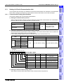
3.1 OS Version and Correspondence to Connected Equipment of GOT-F900 ......... 3-1
3.1.1
3.1.2
3.1.3
3.1.4
How to Confirm OS Version of GOT-F900 ................................................................ 3-1
PLC Manufactured by Mitsubishi............................................................................... 3-2
PLC Manufactured by Other Companies .................................................................. 3-4
Others........................................................................................................................ 3-5
3.2 Version of Screen Creation Software and Correspondence to GOT-F900.......... 3-6
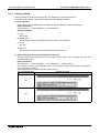
3.2.1 How to Conform Version of Screen Creation Software ............................................. 3-6
3.2.2 Screen Creation Software Version Corresponding to GOT-F900 Series .................. 3-7
3.2.3 Screen Creation Software Corresponding to Each Connected Equipment ............... 3-8
3.3 Device Names Which can be Monitored ........................................................... 3-10
3.3.1 Devices in GOT-F900.............................................................................................. 3-10
3.3.2 PLC by Mitsubishi.................................................................................................... 3-11
3.3.3 PLC Units Manufactured by Other Companies ....................................................... 3-16
3.4 Hardware Specifications .................................................................................... 3-24
4. Installation and Wiring of F920GOT-K/F930GOT(-K)/F940(W)GOT ..............4-1
4.1 Outline of Connection .......................................................................................... 4-3
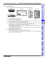
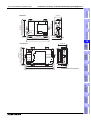
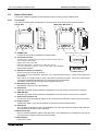
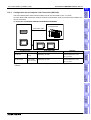
4.2 Name of Each Part .............................................................................................. 4-4
4.2.1 Front Panel ................................................................................................................ 4-4
4.2.2 Rear Panel ................................................................................................................ 4-4
4.2.3 Function of Ports ....................................................................................................... 4-5
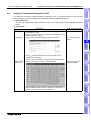
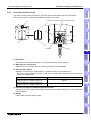
4.3 Processing of Panel Face.................................................................................... 4-7
4.3.1 Panel Cut Dimension................................................................................................. 4-7
4.4 Installation ........................................................................................................... 4-8
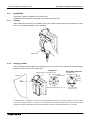
4.4.1 Caution on installation ............................................................................................... 4-8
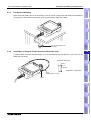
4.4.2 Installation procedure ................................................................................................ 4-9
4.5
4.6
4.7
4.8
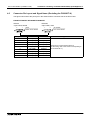
Connector Pin Layout and Signal Name (Excluding the F920GOT-K) .............. 4-12
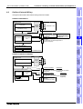
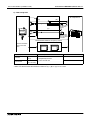
Outline of Internal Wiring ................................................................................... 4-13
Wiring for 24V DC and 5V DC Power Supply and Class D Grounding.............. 4-14
Handling of Function Keys (F1 to F8) ................................................................ 4-17
4.8.1 Use of function keys ................................................................................................ 4-18
4.8.2 Preparation of Function Key Name Sheet (Available in the F930GOT-K)............... 4-19
4.8.3 Label pattern (F930GOT-K) .................................................................................... 4-20
4.9 Setting of Connected Equipment for GOT ......................................................... 4-21
5. Installation and Wiring of Handy GOT ............................................................5-1
5.1 Outline of Connection .......................................................................................... 5-3
5.1.1 Handy GOT (Excluding RH model) ........................................................................... 5-3
5.1.2 Handy GOT (RH model) ............................................................................................ 5-5
vii
GOT-F900 SERIES (CONNECTION)
Contents
5.2 Name of Each Part .............................................................................................. 5-6
5.2.1 Front Panel ................................................................................................................ 5-6
5.2.2 Rear Panel and Connectors ...................................................................................... 5-7
5.3 Installation ........................................................................................................... 5-8
5.3.1
5.3.2
5.3.3
5.3.4
Holding ...................................................................................................................... 5-8
Hanging on Wall ........................................................................................................ 5-8
Flat Surface Mounting ............................................................................................... 5-9
Installation of Strap for Drop Prevention (RH model only)......................................... 5-9
5.4 Selection and Installation of External Cable ...................................................... 5-10
5.4.1 Handy GOT (Excluding RH model) ......................................................................... 5-10
5.4.2 W iring betw een H andy G O T (R H m odel) operation sw itches and connected equipm ent 5-12
5.4.3 Installation of External Cable................................................................................... 5-14
5.5 Processing Panel Face of Control Box or Cabinet ............................................ 5-16
5.5.1
5.5.2
5.5.3
5.5.4
Selection of relay cable ........................................................................................... 5-16
Appearance shape of Relay Cable.......................................................................... 5-18
Panel Cut Dimension for Relay Cable ..................................................................... 5-20
Panel Cut Dimension for F9GT-HCNB .................................................................... 5-20
5.6 Pin Layout and Signal Allocation of Connector for Serial Communication and
Operation Switches ........................................................................................... 5-21
5.6.1 F9GT-HCAB"-"M/F9GT-HCAB1-"M External Cable .......................................... 5-21
5.6.2 F9GT-RHCAB-"M External Cable ......................................................................... 5-22
5.6.3 F9GT-HCNB Conversion Box ................................................................................. 5-23
5.7 Outline of Internal Wiring ................................................................................... 5-24
5.8 Wiring for 24V DC Power Supply and Class D Grounding ................................ 5-26
5.9 Wiring and Handling of Operation Switches SW1 to SW4................................. 5-27
5.9.1 Handling of operation switches ............................................................................... 5-27
5.9.2 Preparation of Operation Switch Name Sheet ........................................................ 5-29
5.10 Wiring and Handling of Emergency Stop Switch (ES1) ..................................... 5-31
5.11 Handling of grip switch (excluding RH model) ................................................... 5-33
5.11.1
5.11.2
5.11.3
5.11.4
Function of Grip Switch ........................................................................................... 5-33
Setting in main unit and screen creation software................................................... 5-33
Grip switch operation specifications ........................................................................ 5-34
Communication with connected equipment (grip switch ON/OFF signal) ............... 5-36
5.12 Handling of grip switch (RH model only) ........................................................... 5-37
5.12.1 Wiring of Grip Switch ............................................................................................... 5-37
5.12.2 Setting of Grip Switch LED ...................................................................................... 5-38
5.12.3 LED Action .............................................................................................................. 5-38
5.13
5.14
5.15
5.16
Handling of Keylock Switch (RH model only) .................................................... 5-39
Setting of Connected Equipment for GOT ......................................................... 5-40
Connection Diagram of Handy GOT Operation Switches and Power Supply ... 5-44
Cable Specification (Optional) ........................................................................... 5-46
6. Connection of Peripheral Equipment
(Screen data transfer/Sequence program transfer and monitor)6-1
6.1 Outline of Connection .......................................................................................... 6-1
6.2 Connection to Personal Computer ...................................................................... 6-3
6.2.1 Screen Data Transfer ................................................................................................ 6-3
6.2.2 Sequence Program Transfer (two-port interface function built)................................. 6-4
6.2.3 Cable Connection Procedure .................................................................................... 6-4
6.3 Connection of F943 Handy GOT (for PLC) and Personal Computer................... 6-7
6.3.1 When Screen Data is transferred through PLC Connector ....................................... 6-7
6.3.2 Changeover of Connection between PLC and Personal Computer .......................... 6-8
6.4 Caution on Use of Peripheral Equipment ............................................................ 6-9
6.4.1 Caution when connecting the GOT and PLC via RS-232C port
(Only in case of the F920GOT-K, F930GOT, F930GOT-K, or F940GOT) ......................... 6-9
6.4.2 Caution when transferring screen data to the F920GOT-K ..................................... 6-10
viii
GOT-F900 SERIES (CONNECTION)
Contents
6.5 Cable Diagram................................................................................................... 6-12
6.5.1 Cable for Personal Computer .................................................................................. 6-12
6.6 Troubleshooting ................................................................................................. 6-13
7. Connection of Two or More GOT Units...........................................................7-1
7.1 System Condition ................................................................................................ 7-1
7.2 Connection Configuration for Two or More GOT Units........................................ 7-2
7.2.1 Configuration When First GOT Unit is Connected through RS-422 .......................... 7-2
7.2.2 When First GOT Unit is Connected through RS-232C .............................................. 7-4
7.2.3 When Connection is Changed from RS-422 to RS-232C.......................................... 7-5
7.3 Rules in Configuration ......................................................................................... 7-6
7.3.1 Connection Method ................................................................................................... 7-6
7.3.2 Communication Port Number Table .......................................................................... 7-7
7.3.3 Connection Concept in Each Model Name ............................................................... 7-7
7.4 Connection of Four or More Display Units........................................................... 7-8
7.5 Cautions on Connecting Two or More GOT Units ............................................... 7-9
7.5.1 Power ON Sequence................................................................................................. 7-9
7.5.2 Transfer of sequence program and use of monitor ................................................. 7-10
7.6 Setting of Connected Equipment for GOT ......................................................... 7-11
7.6.1 Connection Type (RS-422/RS-232C setting) .......................................................... 7-11
7.6.2 Station Number Setting ........................................................................................... 7-11
7.6.3 Setting Procedure.................................................................................................... 7-12
7.7 Cable Diagram................................................................................................... 7-17
7.8 Troubleshooting ................................................................................................. 7-21
8. Connection of MELSEC-F FX Series PLC ......................................................8-1
8.1 System Condition ................................................................................................ 8-1
8.2 System Configuration .......................................................................................... 8-2
8.2.1 Configuration for CPU Direct Connection (RS-422) .................................................. 8-2
8.2.2 Configuration for CPU Direct Connection (RS-232C)................................................ 8-4
8.3 Cautions on Use of MELSEC-F FX Series .......................................................... 8-6
8.3.1
8.3.2
8.3.3
8.3.4
Device specification................................................................................................... 8-6
Devices which can be monitored............................................................................... 8-6
When GOT-F900 is connected to optional port ......................................................... 8-6
Restrictions in connecting two or more F920GOT-K units to FX Series PLC............ 8-9
8.4 Setting of Connected Equipment for GOT ......................................................... 8-10
8.5 Cable Diagram................................................................................................... 8-14
8.6 Troubleshooting ................................................................................................. 8-18
9. Connection of MELSEC-A Series PLC ...........................................................9-1
9.1 System Condition ................................................................................................ 9-2
9.2 System Configuration .......................................................................................... 9-2
9.2.1 Configuration for Direct Connection (RS-422)........................................................... 9-3
9.2.2 Configuration for A Computer Link Connection (RS-422) ......................................... 9-5
9.2.3 Configuration for A Computer Link Connection (RS-232C)....................................... 9-7
9.3 Setting in A Computer Link Connection............................................................... 9-9
9.3.1
9.3.2
9.3.3
9.3.4
9.3.5
Communication Setting Specifications ...................................................................... 9-9
Setting of CD Signal Control (only in RS-232C connection).................................... 9-10
Setting Examples .................................................................................................... 9-11
Used Connectors and Connector Covers................................................................ 9-14
Cable Specifications and Length ............................................................................. 9-14
9.4 Caution on Use of MELSEC-A Series PLC ....................................................... 9-15
9.4.1 Caution when the GOT-F900 is connected to the computer link unit ...................... 9-15
9.4.2 Caution when displaying the Ascii code .................................................................. 9-15
9.5 Setting of Connected Equipment for GOT ......................................................... 9-16
9.6 Cable Diagram................................................................................................... 9-21
9.7 Troubleshooting ................................................................................................. 9-24
ix
GOT-F900 SERIES (CONNECTION)
Contents
10.Connection of MELSEC-QnA Series PLC....................................................10-1
10.1 System Condition .............................................................................................. 10-2
10.1.1 Restriction When Computer Link Unit for A Series is Used..................................... 10-2
10.2 System Configuration ........................................................................................ 10-3
10.2.1 Configuration for Direct Connection (RS-422)......................................................... 10-3
10.2.2 Configuration for QnA Computer Link Connection (RS-422)................................... 10-5
10.2.3 Configuration for QnA Computer Link Connection (RS-232C) ................................ 10-7
10.3 Setting in QnA Computer Link Connection ........................................................ 10-9
10.3.1 Communication Setting Specifications .................................................................... 10-9
10.3.2 Setting Examples .................................................................................................. 10-10
10.4 Caution on Use of MELSEC-QnA Series PLC ................................................ 10-12
10.4.1 Caution when the GOT is connected to the serial communication unit ................. 10-12
10.4.2 Caution when the GOT is connected to the computer link for the A Series PLC .. 10-12
10.5 Setting of Connected Equipment for GOT ....................................................... 10-13
10.6 Cable Diagram................................................................................................. 10-19
10.7 Troubleshooting ............................................................................................... 10-23
11.Connection of MELSEC-Q Series PLC ........................................................11-1
11.1 System Condition .............................................................................................. 11-2
11.2 System Configuration ........................................................................................ 11-3
11.2.1 Configuration for Direct Connection (RS-232C) ...................................................... 11-3
11.2.2 Configuration for Q Computer Link Connection (RS-422) ....................................... 11-5
11.2.3 Configuration for Q Computer Link Connection (RS-232C) .................................... 11-7
11.3 Setting in Q Serial Communication Unit ............................................................ 11-9
11.3.1 Communication Setting Specifications .................................................................... 11-9
11.3.2 Setting by GPPW .................................................................................................. 11-10
11.3.3 Used Connectors and Connector Covers.............................................................. 11-11
11.4 Setting in Q Multi PLC System (Function version -B or later).......................... 11-12
11.4.1 Direct connection to QCPU ................................................................................... 11-12
11.4.2 Connection to serial communication ..................................................................... 11-13
11.5 Caution on Use of MELSEC-Q Series PLC ..................................................... 11-14
11.5.1
11.5.2
11.5.3
11.5.4
Restriction in device specification ......................................................................... 11-14
Caution when the GOT is connected to the serial communication unit ................. 11-14
Caution when connecting to Q multiple CPU system ............................................ 11-14
Caution when setting screen creation software..................................................... 11-15
11.6 Setting of Connected Equipment for GOT ....................................................... 11-16
11.7 Cable Diagram................................................................................................. 11-22
11.8 Troubleshooting ............................................................................................... 11-25
12.Connection of FX Series Positioning Unit (FX(2N)-10/20GM).......................12-1
12.1 System Condition .............................................................................................. 12-1
12.2 System Configuration ........................................................................................ 12-2
12.2.1 Configuration for GMCPU direct connection (RS-422)............................................ 12-2
12.3 Cautions on use of FX Series positioning unit ................................................... 12-4
12.3.1 Device specification................................................................................................. 12-4
12.3.2 Devices which can be monitored............................................................................. 12-4
12.3.3 Caution on connection of a programming tool to the FX Series positioning unit ..... 12-4
12.4 Setting of Connected Equipment for GOT ......................................................... 12-5
12.5 Cable Diagram................................................................................................... 12-8
12.6 Troubleshooting ............................................................................................... 12-10
13.FREQROL (S500/E500/A500) Inverter ........................................................13-1
13.1 System Condition .............................................................................................. 13-2
13.2 System Configuration ........................................................................................ 13-2
13.2.1 Configuration for CPU Direct Connection (RS-422) ................................................ 13-2
x
GOT-F900 SERIES (CONNECTION)
Contents
13.3 Setting in FREQROL Inverter ............................................................................ 13-6
13.3.1
13.3.2
13.3.3
13.3.4
Communication Setting Specifications .................................................................... 13-6
Setting Examples .................................................................................................... 13-7
Inverter Connector Specifications ........................................................................... 13-9
Specification of Station Number in Creating Screen ............................................. 13-10
13.4 Cautions on Use of FREQROL Series Inverter ............................................... 13-11
13.4.1
13.4.2
13.4.3
13.4.4
13.4.5
13.4.6
13.4.7
Device specification............................................................................................... 13-11
Changeover from the GOT (communication) to the PU operation mode .............. 13-11
When "8888" or "9999" is set to a parameter (Pr) of the inverter .......................... 13-11
Specification of the program operation (PG) devices ............................................ 13-12
Caution on setting of the calibration parameters (Pr900 to Pr905) ....................... 13-12
Restriction in simultaneous specification of PG and Pr devices on one screen .... 13-12
Caution on connecting to the PU port (only in the E500 and the A500) ................ 13-12
13.5 Correspondence Between Devices of GOT and Parameters .......................... 13-13
13.6 FREQROL Inverter Parameter List.................................................................. 13-18
13.6.1 Parameters ............................................................................................................ 13-18
13.6.2 Communication Parameters .................................................................................. 13-25
13.7 Setting of Connected Equipment for GOT ....................................................... 13-26
13.8 Cable Diagram................................................................................................. 13-29
13.9 Troubleshooting ............................................................................................... 13-32
14.Connection of Microcomputer ......................................................................14-1
14.1 System Condition .............................................................................................. 14-2
14.2 System Configuration ........................................................................................ 14-3
14.2.1 Configuration for CPU Direct Connection (RS-422) ................................................ 14-3
14.2.2 Configuration for CPU Direct Connection (RS-232C).............................................. 14-5
14.3 Outline of Communication and Specifications ................................................... 14-6
14.3.1 Outline of Communication ....................................................................................... 14-6
14.3.2 Communication Setting Specifications .................................................................... 14-7
14.4 Memory Map...................................................................................................... 14-7
14.4.1 Data Area ................................................................................................................ 14-7
14.4.2 Special Memory Data List ..................................................................................... 14-10
14.4.3 Error Code List ...................................................................................................... 14-12
14.5 Communication Command .............................................................................. 14-13
14.5.1
14.5.2
14.5.3
14.5.4
14.5.5
14.5.6
14.5.7
Outline of Communication Procedure ................................................................... 14-13
Command List and Compatible Version of GOT-F900.......................................... 14-14
Data Transfer Format (protocol) ............................................................................ 14-15
Character Code List .............................................................................................. 14-15
Station Number Setting ......................................................................................... 14-16
Sum Check Code .................................................................................................. 14-16
Interrupt Code List ................................................................................................. 14-17
14.6 Command Details ............................................................................................ 14-18
14.6.1
14.6.2
14.6.3
14.6.4
14.6.5
Batch Read Command (RD) ................................................................................. 14-18
Batch Write Command (WR) ................................................................................. 14-19
Bit-oriented Write Command ................................................................................. 14-20
Fill Command ........................................................................................................ 14-22
Interrupt Code ....................................................................................................... 14-22
14.7 Setting of Connected Equipment for GOT ....................................................... 14-23
14.8 Cable Diagram................................................................................................. 14-28
14.9 Troubleshooting ............................................................................................... 14-30
14.10BASIC Program Example ............................................................................... 14-32
15.Connection of SYSMAC C Series PLC (Manufactured by Omron) ..............15-1
15.1 System Condition .............................................................................................. 15-2
15.1.1 Classification of Host Link/Serial Communication Units .......................................... 15-2
xi
GOT-F900 SERIES (CONNECTION)
Contents
15.2 System Configuration ........................................................................................ 15-3
15.2.1 Configuration for SYSMAC C Host Link Connection (RS-422) ............................... 15-3
15.2.2 Configuration for SYSMAC C Host Link Connection (RS-232C)............................. 15-5
15.3 Setting in CQM1/C200H Host Link Unit............................................................. 15-7
15.3.1 Communication Setting Specifications .................................................................... 15-7
15.3.2 Setting Examples in Host Link Units ....................................................................... 15-7
15.4 Setting in CS1 Serial Communication Unit ...................................................... 15-10
15.4.1 Communication Setting Specifications .................................................................. 15-10
15.4.2 Setting Examples .................................................................................................. 15-11
15.5 Caution on Use of SYSMAC C Series PLC ..................................................... 15-13
15.5.1 Modes in the SYSMAC C Series PLC ................................................................... 15-13
15.5.2 Forced ON/OFF on the device monitor screen of the GOT-F900 ......................... 15-13
15.5.3 Restriction in functions .......................................................................................... 15-13
15.6 Setting of Connected Equipment for GOT ....................................................... 15-14
15.7 Cable Diagram................................................................................................. 15-18
15.8 Troubleshooting ............................................................................................... 15-21
16.Connection of FLEX-PC N Series PLC (Manufactured by Fuji Electric) ......16-1
16.1 System Condition .............................................................................................. 16-1
16.2 System Configuration ........................................................................................ 16-2
16.2.1 Configuration for Link Unit Connection (RS-422) .................................................... 16-2
16.2.2 Configuration for Link Unit Connection (RS-232C).................................................. 16-4
16.3 Setting in Link Unit............................................................................................. 16-5
16.3.1 Communication Setting Specifications .................................................................... 16-5
16.3.2 Setting Examples .................................................................................................... 16-6
16.4 Caution on Use of FLEX-PC N Series PLC ....................................................... 16-7
16.4.1 Devices which can be monitored............................................................................. 16-7
16.5 Setting of Connected Equipment for GOT ......................................................... 16-7
16.6 Cable Diagram................................................................................................. 16-11
16.7 Troubleshooting ............................................................................................... 16-14
17.Connection of Machine Controller CP9200SH
(PLC Manufactured by Yaskawa Electric) ....................................................17-1
17.1 System Condition .............................................................................................. 17-1
17.2 System Configuration ........................................................................................ 17-2
17.2.1 Configuration for CPU Direct Connection (RS-422) ................................................ 17-2
17.2.2 Configuration for CPU Direct Connection (RS-232C).............................................. 17-4
17.3 Setting in Machine Controller ............................................................................ 17-6
17.3.1 Communication Setting Specifications .................................................................... 17-6
17.4 Setting of Connected Equipment for GOT ......................................................... 17-7
17.5 Cable Diagram................................................................................................. 17-10
17.6 Troubleshooting ............................................................................................... 17-13
18.C onnection of F P S eries P LC (M anufactured by M atsushita E lectric W orks) .18-1
18.1 System Condition .............................................................................................. 18-2
18.1.1 Classification of Product Names ............................................................................. 18-2
18.2 System Configuration ........................................................................................ 18-3
18.2.1 Configuration for CPU Direct Connection (RS-232C).............................................. 18-3
18.3 FP Selection ...................................................................................................... 18-5
18.3.1 Communication Setting Specifications .................................................................... 18-5
18.3.2 Setting Examples in Control Unit and CPU Unit...................................................... 18-6
18.3.3 Setting Examples in Computer Communication Unit............................................... 18-7
18.4 Cautions on Use of FP Series ........................................................................... 18-8
18.4.1 Device specification................................................................................................. 18-8
18.4.2 Devices which can be monitored............................................................................. 18-8
18.4.3 Cautions on connection of the control unit, the CPU unit and the computer
communication unit........................................................................................................... 18-8
xii
GOT-F900 SERIES (CONNECTION)
Contents
18.5 Setting of Connected Equipment for GOT ......................................................... 18-9
18.6 Cable Diagram................................................................................................. 18-12
18.7 Troubleshooting ............................................................................................... 18-15
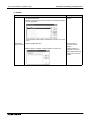
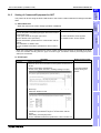
19.Connection of SLC500/MicroLogix Series PLC (Manufactured by Allen-Bradley)191
19.1 System Condition .............................................................................................. 19-2
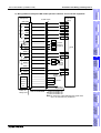
19.2 System Configuration ........................................................................................ 19-3
19.2.1 Configuration for CPU Direct Connection (RS-232C).............................................. 19-3
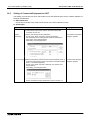
19.3 Setting in SLC500.............................................................................................. 19-5
19.3.1 Communication Setting Specifications .................................................................... 19-5
19.3.2 GOT-F900 Transmission Specifications.................................................................. 19-5
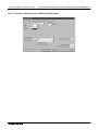
19.3.3 Example of Setting Screen of RSLogix500 Software .............................................. 19-6
19.4 Setting in MicroLogix ......................................................................................... 19-7
19.4.1 Communication Setting Specifications .................................................................... 19-7
19.4.2 GOT-F900 Transmission Specifications.................................................................. 19-7
19.4.3 Examples of Setting Screen of RSLogix500 Software ............................................ 19-8
19.5 Device Specification Method ............................................................................. 19-9
19.5.1 Device Format ......................................................................................................... 19-9
19.5.2 File Number and Element Range .......................................................................... 19-11
19.5.3 Restriction in Device Specification ........................................................................ 19-11
19.6 Caution on Use of SLC500/MicroLogix Series PLC ........................................ 19-12
19.6.1 Device setting in advance ..................................................................................... 19-12
19.6.2 Caution on use of the sampling function ............................................................... 19-12
19.7 Setting of Connected Equipment for GOT ....................................................... 19-13
19.8 Cable Diagram................................................................................................. 19-17
19.9 Troubleshooting ............................................................................................... 19-19
20.Connection of SIMATIC S7-200/300/400 Series PLC
(Manufactured by Siemens AG)....................................................................20-1
20.1 System Condition .............................................................................................. 20-2
20.2 System Configuration ........................................................................................ 20-3
20.2.1 Configuration for CPU Direct Connection (RS-232C).............................................. 20-3
20.2.2 Introduction of Options Manufactured by Siemens AG ........................................... 20-5
20.3 Setting in SIMATIC S7-200 ............................................................................... 20-6
20.3.1 Communication Setting Specifications .................................................................... 20-6
20.3.2 GOT-F900 Transmission Specifications.................................................................. 20-8
20.4 Setting in SIMATIC S7-300/400 ........................................................................ 20-8
20.4.1 Communication Setting Specifications .................................................................... 20-8
20.4.2 GOT-F900 Transmission Specifications.................................................................. 20-8
20.5 Device Specification Method ............................................................................. 20-9
20.5.1 Device Format in SIMATIC S7-200 ......................................................................... 20-9
20.5.2 Device Format in SIMATIC S7-300/400 ................................................................ 20-10
20.5.3 Supplementary Items ............................................................................................ 20-11
20.6 Caution on Use of SIMATIC S7-200/300/400 Series PLC .............................. 20-11
20.6.1 Restriction in devices depending on the model ..................................................... 20-11
20.6.2 Restriction in device specification ......................................................................... 20-11
20.7 Setting of Connected Equipment for GOT ....................................................... 20-12
20.8 Cable Diagram................................................................................................. 20-17
20.9 Troubleshooting ............................................................................................... 20-19
xiii
GOT-F900 SERIES (CONNECTION)
Contents
21.Connection of Printer....................................................................................21-1
21.1 System Condition .............................................................................................. 21-1
21.2 System Configuration ........................................................................................ 21-2
21.2.1 Configuration for Printer Connection ....................................................................... 21-2
21.2.2 Applicable port on GOT-F900 ................................................................................. 21-2
21.3 Printer Communication Setting .......................................................................... 21-2
21.3.1 Transmission Specifications and Communication Format....................................... 21-2
21.4 Cautions on Use of Printer ................................................................................ 21-4
21.4.1 Caution on printer setting ........................................................................................ 21-4
21.4.2 Concurrent use of microcomputer and printer ......................................................... 21-4
21.5 Setting of Connected Equipment for GOT ......................................................... 21-5
21.6 Cable Diagram................................................................................................... 21-6
22.Connection of Bar Code Reader ..................................................................22-1
22.1 System Condition .............................................................................................. 22-2
22.2 Connection Configuration .................................................................................. 22-2
22.2.1 Configuration for Bar Code Reader Connection ..................................................... 22-2
22.3 Bar Code Reader Communication Setting ........................................................ 22-3
22.3.1
22.3.2
22.3.3
22.3.4
Transmission Specifications and Communication Format....................................... 22-3
Bar Code Reader Control Devices .......................................................................... 22-4
Bar Code Data Setting ............................................................................................ 22-5
Sequence Program Example .................................................................................. 22-6
22.4 Caution on Use of Bar Code Reader ................................................................. 22-7
22.4.1 Caution on bar code reader setting ......................................................................... 22-7
22.5 Setting of Connected Equipment for GOT ......................................................... 22-8
22.6 Cable Diagram................................................................................................. 22-10
22.7 Troubleshooting ............................................................................................... 22-10
23.Appendix ......................................................................................................23-1
23.1 Connection of Programming Tools via FX-2PIF ................................................ 23-2
23.1.1
23.1.2
23.1.3
23.1.4
23.1.5
How to Monitor Using A6GPP/A7PHP/HPP ............................................................ 23-2
Restrictions in Number of Devices Monitored When Using FX-2PIF ...................... 23-4
Switch Setting in FX-2PIF ....................................................................................... 23-6
Cautions on Use of FX-2PIF ................................................................................... 23-7
Cable Diagram ........................................................................................................ 23-8
23.2 GOT-F900 Connector Signal Correspondence Table
(Excluding the F920GOT-K) .............................................................................. 23-9
23.2.1 RS-422 Correspondence Table .............................................................................. 23-9
23.2.2 RS-232C Correspondence Table ........................................................................... 23-9
23.3 Error Messages in GOT-F900 Series .............................................................. 23-10
23.3.1 Error Messages During Screen Operation ............................................................ 23-12
xiv
GOT-F900 SERIES (CONNECTION)
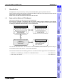
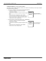
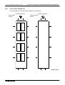
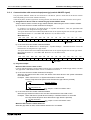
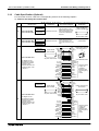
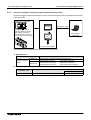
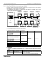
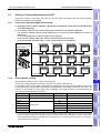
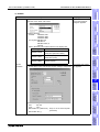
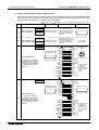
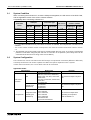
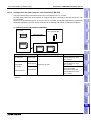
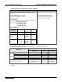
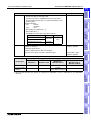
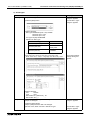
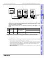
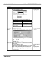
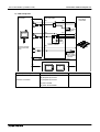
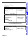
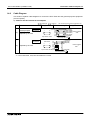
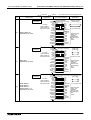
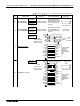
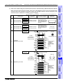
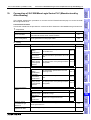
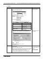
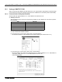
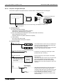
Introduction 1
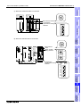
Introduction
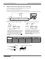
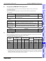
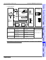
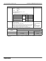
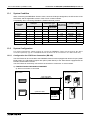
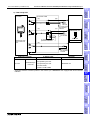
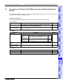
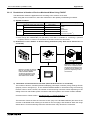
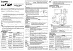
The following manuals are offered for the GOT-F900 Series.
Each manual is classified in accordance with the purpose. Read a manual suitable to your purpose,
then understand handling, the operations and the function of the GOT and the screen creation software
GT Designer (SW"D5C-GOTR-PACKE) or FX-PCS-DU/WIN-E.
Screen creation software
INSTALLATION MANUAL
(included with main unit)
SW"D5C-GOTR-PACKE
(included with unit)
OPERATION MANUAL
(send separately)
FX-PCS-DU/WIN-E
4
installation
and Wiring of
F940GOT
GOT
3
Specifications
Rank and Use Method of This Manual
(included with unit)
Connected equipment
.
.
.
.
PLC by Mitsubishi
PLC by another company
Microcomputer board
Bar code reader
6
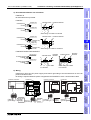
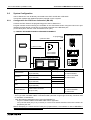
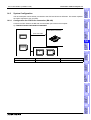
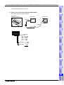
This manual describes how to set the screen creation software, select cables and perform wiring in
connecting the GOT-F900 Series to a connected equipment.
Connection of
Peripheral
Equipment
GOT-F900 SERIES HARDWARE
MANUAL
(CONNECTION)
(this manual)
installation
and Wiring of
Handy GOT
5
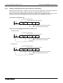
This manual is divided into the following portions in accordance with the type of the GOT-F900 Series.
•
F920GOT-K, F930GOT(-K), F940GOT or F940WGOT Series ................................. From Section 4
•
F940 Handy GOT Series ........................................................................................... From Section 5
Connection of
Two or More
GOT Units
7
Connection of
MELSEC-F
FX Series PLC
8
9
Connection of
MELSEC-A
Series PLC
1.1
2
Outline
We appreciate it very much that you have purchased Mitsubishi graphic operation terminal.
Please read thoroughly this manual to understand sufficiently and use correctly the functions and the
performance of the graphic operations terminal.
Please make sure that this manual is delivered to the end user.
10
1-1
Connection of
MELSEC-QnA
Series PLC
1.
Introduction
1
GOT-F900 SERIES (CONNECTION)
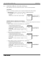
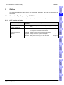
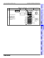
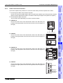
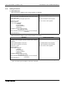
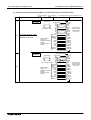
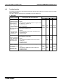
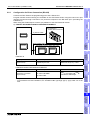
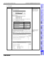
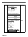
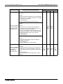
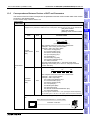
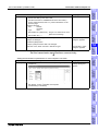
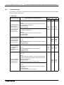
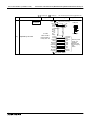
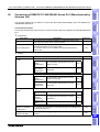
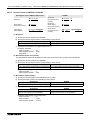
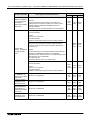
1.1.1
Introduction 1
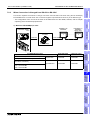
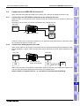
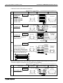
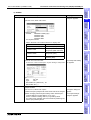
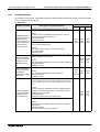
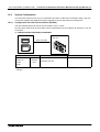
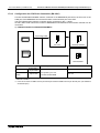
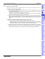
Classification of Manuals in Accordance with Purpose
When requiring a manual not included with the product, contact our sales representative.
THIS MANUAL
Describes in details the connection to a PLC or personal computer and the setting method.
•
GOT-F900 SERIES GRAPHIC OPERATION TERMINAL HARDWARE MANUAL
(CONNECTION)
-
To understand how to connect the main unit to
equipment.
To learn how to set the screen creation software.
HARDWARE
MANUAL
It is stored as a P D F file in
the C D -R O M of the
SW "D 5C -G O TR -PA C KE .
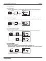
HARDWARE MANUAL AND INSTALLATION MANUAL
Describes mainly the outside dimension, the installation, the power supply wiring and the electrical
specifications.
•
F920GOT-BBD5-K-E INSTALLATION MANUAL (No. JY997D02201)
-
•
INSTALLATION
MANUAL
It is included with the
F920GOT-BBD5-K-E.
F930GOT INSTALLATION MANUAL (No. JY992D95701)
-
•
To learn the features of the main unit.
To confirm the specifications of the main unit.
To learn the name of each part of the main unit.
To learn how to install the main unit and wire the
power supply.
To look at the external dimensions diagram of the
main unit.
To learn the features of the main unit.
To confirm the specifications of the main unit.
To learn the name of each part of the main unit.
To learn how to install the main unit and wire the
power supply.
To look at the external dimensions diagram of the
main unit.
INSTALLATION
MANUAL
It is included with the
F93"GOT-BWD-E.
F930GOT-BBD-K-E INSTALLATION MANUAL (No. JY997D02501)
-
To learn the features of the main unit.
To confirm the specifications of the main unit.
To learn the name of each part of the main unit.
To learn how to install the main unit and wire the
power supply.
To look at the external dimensions diagram of the
main unit.
INSTALLATION
MANUAL
It is included with the
F930GOT-BBD-K-E.
1-2
GOT-F900 SERIES (CONNECTION)
Introduction 1
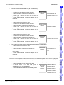
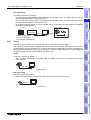
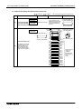
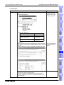
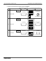
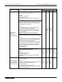
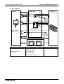
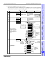
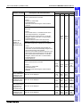
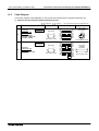
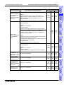
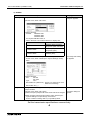
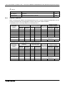
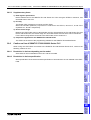
F940GOT INSTALLATION MANUAL (No. JY992D94201)
It is included with the
F940WGOT-TWD-E.
installation
and Wiring of
F940GOT
4
HARDWARE
MANUAL
5
It is included w ith the
F94 "G O T-S B D -H -E and
F94 "G O T-LB D -H -E .
6
F940 HANDY GOT (RH model) HARDWARE MANUAL (No. JY992D99901)
-
To learn the features of the main unit.
To confirm the specifications of the main unit.
To learn the name of each part of the main unit.
To learn how to install the main unit and wire the
power supply.
To look at the external dimensions diagram of the
main unit.
HARDWARE
MANUAL
It is included w ith the
F94 "G O T-S B D -R H -E
and
F94 "G O T-LB D -R H -E .
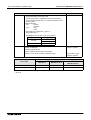
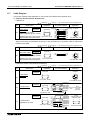
OPERATION MANUAL of GOT
Describes how to operate system screens and how to create and operate user screens display, and
covers all of the F930GOT, F940GOT and Handy GOT Series.
•
GOT-F900 SERIES OPERATION MANUAL (No. JY992D94701) : (Essential)
-
To learn the display function of the GOT-F900.
To execute items in the HPP mode (such as
"PROGRAM LIST" and "MONITOR").
To execute "DEVICE MONITOR" and display alarms.
installation
and Wiring of
Handy GOT
-
To learn the features of the main unit.
To confirm the specifications of the main unit.
To learn the name of each part of the main unit.
To learn how to install the main unit and wire the
power supply.
To look at the external dimensions diagram of the
main unit.
Specifications
INSTALLATION
MANUAL
F940 HANDY GOT HARDWARE MANUAL (No. JY992D86901)
-
•
3
Connection of
Peripheral
Equipment
-
To learn the features of the main unit.
To confirm the specifications of the main unit.
To learn the name of each part of the main unit.
To learn how to install the main unit and wire the
power supply.
To look at the external dimensions diagram of the
main unit.
2
Outline
F940WGOT INSTALLATION MANUAL (No. JY992D93901)
-
•
It is included with the
F94"GOT-SWD-E and
F94"GOT-LWD-E.
7
Connection of
Two or More
GOT Units
•
INSTALLATION
MANUAL
GOT-F900
SERIES
OPERATION
MANUAL
Applicable GOT
F920GOT-BBD5-K-E
F930GOT-BWD-E
F930GOT-BBD-K-E
F94"GOT-SWD-E
F94"GOT-LWD-E
F940WGOT-TWD-E
F94"GOT-SWD-H-E
F94"GOT-LBD-H-E
8
Connection of
MELSEC-F
FX Series PLC
-
To learn the features of the main unit.
To confirm the specifications of the main unit.
To learn the name of each part of the main unit.
To learn how to install the main unit and wire the
power supply.
To look at the external dimensions diagram of the
main unit.
9
Connection of
MELSEC-A
Series PLC
-
10
1-3
Connection of
MELSEC-QnA
Series PLC
•
Introduction
1
GOT-F900 SERIES (CONNECTION)
Introduction 1
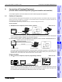
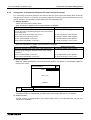
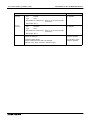
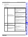
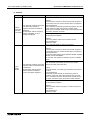
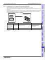
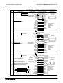
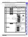
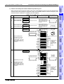
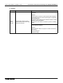
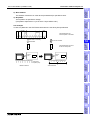
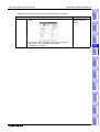
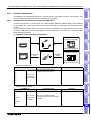
OPERATION MANUAL of screen creation software
Two types of screen creation software are offered. The manual of the software you are using is required
(It is included with the software.).
•
GT Designer (SW"D5C-GOTR-PACKE) OPERATING MANUAL
-
•
To install the software to the personal computer.
To start up the software.
To learn how to connect the personal computer to the
GOT.
To learn the screen configuration of the software.
To learn the outline of diversified monitoring functions.
To learn the procedure to display the monitor screen.
To learn how to use the help function.
SW"D5CGOTR-PACKE
OPERATING
MANUAL
It is included w ith the
SW "D 5C -G O TR -PA C KE .
FX-PCS-DU/WIN-E OPERATION MANUAL (No: JY992D68301)
-
To install the software to the personal computer.
To start up the software.
To learn how to connect the personal computer to the
GOT.
To learn the screen configuration of the software.
To learn how to use the help function.
FX-PCS-DU/
WIN-E
OPERATION
MANUAL
It is included with the
FX-PCS-DU/WIN-E.
1-4
GOT-F900 SERIES (CONNECTION)
Introduction 1
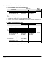
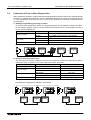
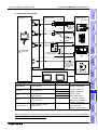
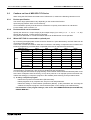
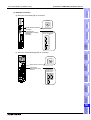
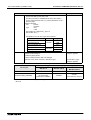
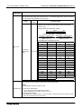
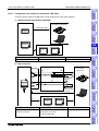
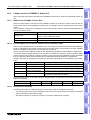
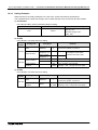
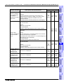
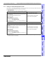
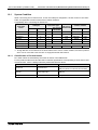
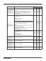
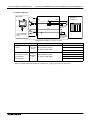
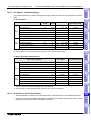
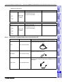
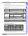
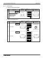
Abbreviations, Generic Names and Terms Used in This Manual
Abbreviations, generic names and terms used in this manual are shown below.
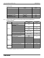
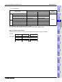
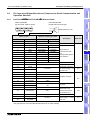
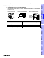
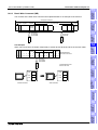
Types and Names of GOT-F900 Series
F930GOT
2
Handy GOT
Outline
F940GOT
F920GOT-K
F930GOT-K
G R IP S W
P O W E R
Specifications
3
P O W E R
F940WGOT-TWD-E,F940WGOT-TWD-C
Remarks
RS-422 ×1
RS-232C ×2
Japanese models
F940GOT-SWD,F940GOT-LWD
RS-422 ×1
RS-232C×1
Japanese models
F940GOT-SWD-E,F940GOT-LWD-E
F940GOT-SWD-C,F940GOT-LWD-C
RS-422 ×1
RS-232C×1
World spec models
F943GOT
F943GOT-SWD,F943GOT-LWD
RS-232C ×2
Japanese models
F930GOT-K
(With various
key-pads)
F930GOT-BBD-K
F940GOT
F930GOT-BBD-K-E
RS-422 ×1
RS-232C×1
F930GOT-BBD-K-C
Japanese models
World spec models
World spec models
F930GOT-BWD
GOT-F900
Series
World spec models
Japanese models
F930GOT
F930GOT-BWD-E
F930GOT-BWD-C
F930GOT-BWD-T
RS-422 ×1
RS-232C ×1
World spec models
F933GOT
F933GOT-BWD
RS-232C ×2
Japanese models
F920GOT-K
(With various
key-pads)
F920GOT-BBD5-K
F940 handy
GOT *1
F943 handy
GOT *1
F920GOT-BBD-K-E
F920GOT-BBD-K-C
F940GOT-SBD-H,F940GOT-LBD-H
F940GOT-SBD-RH,F940GOT-LBD-RH
F940GOT-SBD-H-E,F940GOT-LBD-H-E
F940GOT-SBD-RH-E,F940GOT-LBD-RH-E
F943GOT-SBD-H,F943GOT-LBD-H
F943GOT-SBD-RH,F943GOT-LBD-RH
F943GOT-SBD-H-E,F943GOT-LBD-H-E
F943GOT-SBD-RH-E,F943GOT-LBD-RH-E
RS-422 ×1
RS-232C ×1
Japanese models
World spec models
World spec models
Japanese models
RS-422 ×1
World spec models
Japanese models
RS-232C ×1
World spec models
*1 In addition to the interface shown in the table, an RS-232C interface is built in for connection of a personal
computer.
-
Both the F940 Handy GOT and the F943 Handy GOT are generally called "Handy GOT".
1-5
5
installation
and Wiring of
Handy GOT
F940WGOT-TWD
Built-in I/F
6
Connection of
Peripheral
Equipment
F940WGOT
Model name
7
Connection of
Two or More
GOT Units
Name
8
Connection of
MELSEC-F
FX Series PLC
Generic
name
installation
and Wiring of
F940GOT
4
9
Connection of
MELSEC-A
Series PLC
1.2.1
10
Connection of
MELSEC-QnA
Series PLC
1.2
Introduction
1
GOT-F900 SERIES (CONNECTION)
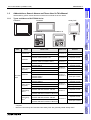
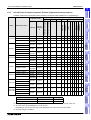
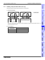
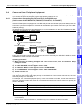
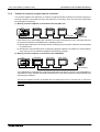
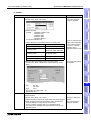
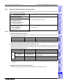
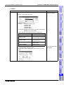
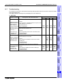
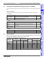
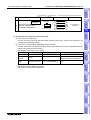
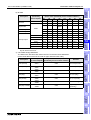
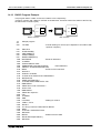
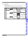
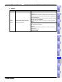
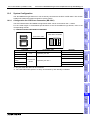
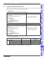
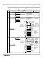
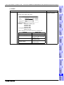
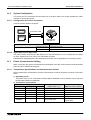
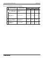
1.2.2
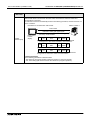
Introduction 1
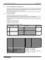
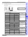
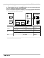
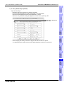
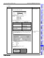
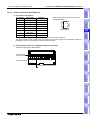
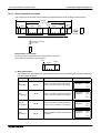
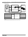
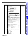
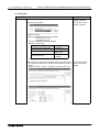
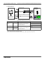
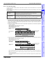
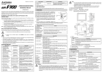
Information Offered by Model Name
GOT
F9"""GOT-####-#-#-#
1) 2) 3)
4) 5) 6) 7) 8) 9)
1) LC display size
2: 3 in.
3: 4 in.
4: 6 in. (7 in. in F940WGOT)
2) PLC connection specifications
0: RS-422,RS-232C Interface
3: RS-232C × 2ch interface
In the case of Handy GOT
0: RS-422 Interface
3: RS-232C interface
3) Screen shape
None: Standard
W: Wide screen
4) Screen color
T: TFT type 256-color LCD
S: STN type 8-color LCD
L: STN type black-and-white LCD
B: STN type blue LCD
5) Panel color
W: White
B: Black
6) Input power supply specifications
D: 24V DC
D5: 5V DC
7) Various keys
None: Not with a key
K: With a key
8) Type
None: Panel face installation type
H: Handy GOT
RH: Handy GOT
9) Overseas models
E:
C: In-built fonts vary depending on model.
T: For details, refer to the next page.
1-6
GOT-F900 SERIES (CONNECTION)
Introduction 1
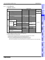
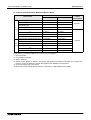
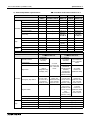
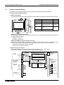
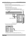
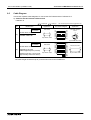
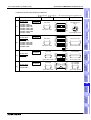
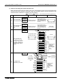
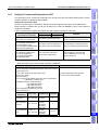
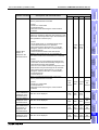
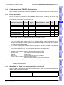
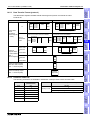
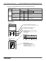
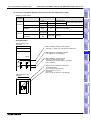
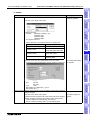
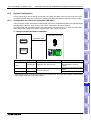
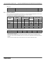
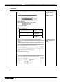
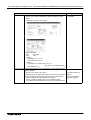
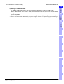
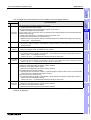
In-built Fonts of Graphic Operation Terminal (Japanese/Overseas product)
Carefully confirm the in-built fonts when selecting a model from the F920GOT-K or F930GOT(-K).
$
$ $ $ $ $ $ $
$
$
$ $ $ $ $ $ $
F940WGOT-TWD-C
Chinese
(Simplified)
English
$
$
$
$
$
$
$ $ $ $ $ $ $
Japanese
English
$
−
$
$
$
$
$ $ $ $ $ $ $
English
Japanese
$
−
$
$
$
$
$ $ $ $ $ $ $
installation
and Wiring of
F940GOT
Chinese
(Simplified)
English
$
−
$
$
$
$
$ $ $ $ $ $ $
5
F940GOT-LWD-C
F930GOT-BBD-K
Japanese
English
$
−
$
−
−
−
$ $ $ $ $ $ $
−
−
$ $ $ $ $ $ $
F940GOT-SWD-E
F940GOT-LWD-E
F940GOT-SWD-C
F930GOT-K
F930GOT-BBD-K-E
English
Japanese
$
−
$
$*4
F930GOT-BBD-K-C
Chinese
(Simplified)
English
−
−
$
−
$
−
−
Japanese
English
$
−
$
−
−
−
$ $ $ $ $ $ $
−
−
$ $ $ $ $ $ $
F93"GOT-BWD
F920GOT-K
−
−
−
−
F930GOT-BWD-E
English
Japanese
$
−
$
$*4
F930GOT-BWD-C
Chinese
(Simplified)
English
−
−
$
−
$
−
−
−
−
−
−
−
−
F930GOT-BWD-T
English
−
−
−
$
−
−
$
−
−
−
−
−
−
−
F920GOT-BBD5-K
Specifications
6
Japanese
English
$
$
$
−
−
−
$ $ $ $ $ $ $
F920GOT-BBD5-K-E
English
Japanese
$
$
$
$*4
−
−
$ $ $ $ $ $ $
F920GOT-BBD5-K-C
Chinese
(Simplified)
English
−
−
$
−
$
$
−
Japanese
English
$
−
$
$
$
$
$ $ $ $ $ $ $
English
Japanese
$
−
$
$
$
$
$ $ $ $ $ $ $
8
Japanese
English
$
−
$
$
$
$
$ $ $ $ $ $ $
English
Japanese
$
−
$
$
$
$
$ $ $ $ $ $ $
F94"GOT-SBD-H
Handy GOT
−
Connection of
Two or More
GOT Units
F930GOT
−
F94"GOT-LBD-H
F94"GOT-SBD-H-E
F94"GOT-LBD-H-E
F94"GOT-SBD-RH
Handy GOT F94"GOT-LBD-RH
(RH model) F94"G O T-S B D -R H -E
F 94"G O T-LB D -R H -E
−
−
−
0
RS-422(1), RS-232C(1)
Handy GOT, Handy GOT RH model RS-422(1)
−
Connection of
MELSEC-A
Series PLC
Name
−
9
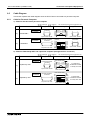
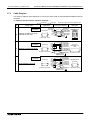
*1 " in the GOT model name indicates 0 or 3. (The in-built interface varies as shown below.)
F940GOT, F930GOT
−
7
Connection of
MELSEC-F
FX Series PLC
F940GOT
4
installation
and Wiring of
Handy GOT
F94"GOT-LWD
3
Connection of
Peripheral
Equipment
F94"GOT-SWD
Outline
$
$
French
$
$
Portuguese
$
$
German
Italian
$
$
Spanish
Traditional
$
Japanese
Dutch
Simplified
English
English
F940WGOT-TWD
Can be
switched
to
Swedish
Shift JIS level-2 kanji set
Japanese
At factory
F940WGOT
2
Western Europe
F940WGOT-TWD-E
GOT model name *1
Name
In-built fonts (user screen) *3
Japanese English Korean Chinese
Shift JIS level-1 kanji set
Language displayed
on system screen *2
3
RS-232C(2)
RS-232C(1)
*2 A change on a system screen can be made in the screen creation software or GOT main unit.
*3 The font which can be displayed on a user screen
Depending on the OS, the font may not be displayed even if it is built in the GOT-F900.
*4 Only the Hangul is available.
1-7
10
Connection of
MELSEC-QnA
Series PLC
1.2.3
Introduction
1
GOT-F900 SERIES (CONNECTION)
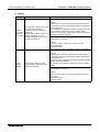
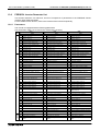
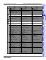
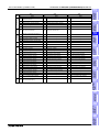
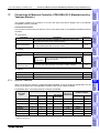
1.2.4
Introduction 1
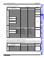
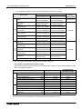
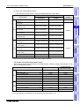
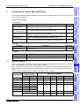
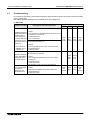
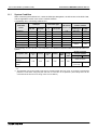
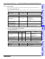
Abbreviation List
Abbreviation/generic name/term
CPU
Description
QCPU(Q mode)
Generic name of Q00JCPU, Q00CPU, Q01CPU, Q02CPU, Q02HCPU,
Q06HCPU, Q12HCPU and Q25HCPU units
QCPU(A mode)
Generic name of Q02CPU-A, Q02HCPU-A and Q06HCPU-A units
QCPU
Generic name of QCPU (Q mode) and QCPU (A mode) units
QnACPU(large type)
Generic name of Q2ACPU, Q2ACPU-S1, Q3ACPU, Q4ACPU and
Q4ARCPU units
QnACPU(small type)
Generic name of Q2ASCPU, Q2ASCPU-S1, Q2ASHCPU and
Q2ASHCPU-S1 units
QnACPU
Generic name of QnACPU (large type) and QnACPU (small type) units
AnUCPU
Generic name of A2UCPU, A2UCPU-S1, A3UCPU and A4UCPU units
AnACPU
Generic name of A2ACPU, A2ACPU-S1 and A3ACPU units
AnNCPU
Generic name of A1NCPU, A2NCPU, A2NCPU-S1 and A3NCPU units
ACPU(large type)
Generic name of AnUCPU, AnACPU and AnNCPU units
A2US(H)CPU
Generic name of A2USCPU, A2USCPU-S1 and A2USHCPU-S1 units
AnS(H)CPU
Generic name of A1SCPU, A1SHCPU and A2SCPU units
A1SJ(H)CPU
Generic name of A1SJCPU-S3 and A1SJHCPU units
ACPU(small type)
Generic name of A2US(H)CPU, AnS(H)CPU and A1SJ(H)CPU units
ACPU
G eneric nam e of AC P U (large type), AC P U (sm all type) and A 1FXC PU units
FX0 Series
Generic name of FX0 Series main units
FX0S Series
Generic name of FX0S Series main units
FX1S Series
Generic name of FX1S Series main units
FX0N Series
Generic name of FX0N Series main units
FX1N Series
Generic name of FX1N Series main units
FX1 Series
Generic name of FX1 Series main units
FX Series
Generic name of FX Series main units
FX2 Series
Generic name of FX2 Series main units
FX2N Series
Generic name of FX2N Series main units
FX2C Series
Generic name of FX2C Series main units
FX2NC Series
Generic name of FX2NC Series main units
FXCPU
Generic name of FX0/FX0S/FX1S/FX0N/FX1N/FX1/FX/FX2/FX2N/FX2C/
FX2NC Series main units
FX Series GM
positioning unit
FX-10GM, FX-20GM, E-20GM, FX2N-10GM and FX2N-20GM
Motion controller CPU
Generic name of A171SCPU-S3, A171SHCPU, A172SHCPU and
A273UHCPU
FREQROL Series
A500/E500/S500 Series inverter
1-8
GOT-F900 SERIES (CONNECTION)
Introduction 1
Description
PLC by Omron
Generic name of C200H, CQM1, CS1 and A273UHCPU
PLC by Fuji Electric
Generic name of FLEX-PC N Series
(NB-RS1-AC, NB-RS1-DC, NJ-RS4, NJ-RS1 and NJ-RS2)
PLC by Yasukawa
Electric
G eneric nam e of m achine controllers C P-9200S H , M P -920 and M P -930
Outline
FP0, FP2SH and FP2SH+FP2-CCU
PLC by Allen Bradley
Generic name of SLC 5/03 and SLC 5/04
PLC by Siemens
Generic name of SIMATIC S7-200, S7-300 and S7-400
PLC by another
company
Generic name of PLC manufactured by Omron, Fuji Electric, Yasukawa
Electric, Allen-Bradley or Siemens
OS
Abbreviation of GOT system software
Others
Screen creation software for GOT900
SW"D5C-GOTRSeries SW"D5C-GOTR-PACKE (English
PACKE
version)
S oftw are dedicated to version upgrade
SW"D5C-GOTRfrom conventional version to latest
PACKEV
S W "D 5C -G O TR -PA C K E (E nglish version)
DU/WIN
Abbreviation of screen creation software FX-PCS-DU/WIN-E for GOT-F900
Series
FX/WIN
Abbreviation of programming software FX-PCS/WIN-E for FX Series PLC
Data conversion
software
Abbreviation of data conversion software GOT Converter for GOT900
Series
Debugging software
Abbreviation of debugging software GOT Debugger
Object
Parts and setting data on the screen.
Windows95
Abbreviation of Microsoft Windows95
Windows98
Abbreviation of Microsoft Windows98
Windows NT4.0
Abbreviation of Microsoft Windows NT Workstation 4.0
Windows 2000
Abbreviation of Microsoft Windows 2000 Professional
Windows
Generic name of Windows95, Windows98, Windows NT4.0 and
Windows2000
Personal computer
(PC)
Personal computer compatible with Windows to which GT Designer or FXPCS-DU/WIN-E is installed
GX Developer
6
Remarks
8
9
Abbreviation of software package SW"D5C-GPPW-E
Connection of
MELSEC-A
Series PLC
GPPW
New name
5
7
This manual describes the following product in the new name.
Conventional name
4
installation
and Wiring of
F940GOT
GT
Designer
Integrated screen development software
for GOT900 Series (SW"D5C-GOTRPACKE + GT Simulator) (English version)
installation
and Wiring of
Handy GOT
GT Designer
SW"D5CGTWORKS-E
Connection of
Two or More
GOT Units
GT
Works
Connection of
Peripheral
Equipment
Abbreviation of screen creation software for GOT-A900/GOT-F900 Series
Specifications
3
Connection of
MELSEC-F
FX Series PLC
PLC by
other
PLC by Matsushita
companies Electric Works
2
10
1-9
Connection of
MELSEC-QnA
Series PLC
Abbreviation/generic name/term
Introduction
1
GOT-F900 SERIES (CONNECTION)
Introduction 1
Abbreviation/generic name/term
Description
BK
Black
W
White
Y
Yellow
BR
Brown
BL
Blue
GY
Connection
O
diagram
PL
Gray
PK
Pink
FGR
Fresh green
SB
Sky blue
R
Red
GR
Green
Orange
Purple
1-10
GOT-F900 SERIES (CONNECTION)
Outline 2
Outline
This section describes the outline of PLC, bar code reader, printer, etc. which can be connected to the
GOT-F900.
The table below shows connection types supported by the GOT-F900 having the lastest OS version.
GOT type list and index
Connection
destination
3
Description
Reference
F920GOT-K,
F930GOT, F930GOT-K,
F940GOT, F940WGOT
−
Name of each part, installation and power supply
wiring
Chapter 4
Handy GOT
−
Dedicated wiring and functions of Handy GOT such
as name of each part, installation, cables dedicated
to Handy GOT and switch control method
Chapter 5
Peripheral
equipment
Transfer of screen data and sequence programs
through connection of personal computer
Chapter 6
Connection of two or more GOT
units
GOT-GOT
Wiring when connecting up to four GOT units
Chapter 7
4
5
installation
and Wiring of
Handy GOT
Connection of peripheral
equipment
Specifications
Connected equipment
Connection of
Peripheral
Equipment
6
Connection of
Two or More
GOT Units
7
Connection of
MELSEC-F FX
Series PLC
8
9
Connection of
MELSEC-A
Series PLC
2.1.1
Outline
Connection Type Supported by GOT-F900
installation
and Wiring of
F940GOT
2.1
2
10
2-1
Connection of
MELSEC-QnA
Series PLC
2.
Introduction
1
GOT-F900 SERIES (CONNECTION)
2.1.2
Outline 2
Connection type list and index
"$" indicates can connect. "−" indicates cannot connect.
Manufacturer
Connected
equipment
Others
CC-Link
(F9GT-CCL)
-
RS-422
Connection
of two or
Reference
m ore GOT
RS-232C
units
FX Series
CPU direct connection
$
$
$
CPU direct connection
$
−
$
A computer link
$
$
−
CPU direct connection
$
−
$
A computer link
$
$
−
QnA computer link
$
$
$
CPU direct connection
−
$
$
Serial com m unication unit
(C PU direct connection)
$
$
$
CPU direct connection
−
$
$
Serial com m unication unit
(C PU direct connection)
$
$
$
FX positioning unit
(10GM/20GM)
CPU direct connection
$
−
−
Chapter 12
FREQROL Series
(inverter)
CPU direct connection
$
−
−
Chapter 13
General-purpose
equipment such as
CPU direct connection
microcomputer board
$
$
$
Chapter 14
SYSMAC C Series by
Upper link
Omron
$
$
−
Chapter 15
FLEX-PC N Series by
Link unit
Fuji Electric
$
$
−
Chapter 16
CPU direct connection
Machine controller by (memo bus)
Yasukawa Electric
Memo bus unit
−
$
−
$
$
−
Q Series (Q mode)
Q Series (multi CPU)
PLC by other
companies
Transmission
specifications
A Series
Motion controller
Q Series (A mode)
QnA Series
PLC by
Mitsubishi
Connection
destination
Chapter 8
Chapter 9
Chapter 10
Chapter 11
Chapter 11
Chapter 17
FP Series by
Matsushita Electric
Works
CPU direct connection
−
$
−
Chapter 18
SLC500/MicroLogix
Series by AllenBradley
CPU direct connection
−
$
−
Chapter 19
SIMATIC S7-200
SIMATIC S7-300
Series by Siemens
CPU direct connection
−
$
−
Chapter 20
General-purpose
printer
−
−
$
−
Chapter 21
Bar code reader
−
−
$
−
Chapter 22
Q Series (Q mode)
CPU direct connection
$
−
−
Q Series (multi CPU)
CPU direct connection
$
−
−
Chapter 23
For the details of the connection type in accordance with the OS version of the GOT-F900, refer to
section 3.1.
2-2
GOT-F900 SERIES (CONNECTION)
Outline 2
This section describes the outline of connection of the GOT-F900 to the PLC manufactured by
Mitsubishi.
" indicates that a PLC programming tool (personal computer) can be connected.
(Program transfer and monitoring are available using the programming software for the FX/A/QnA/Q
Series.)
FX Series PLC
1) CPU direct connection (RS-422)
GOT-F900 is connected to the programming port of the FX Series PLC. When a personal computer
is connected to the GOT-F900, sequence programs can be created.
E ith e r o n e u n it*1 ( a p e r s o n a l c o m p u te r a n d
o n e u n it in F 9 4 0 W G O T )
installation
and Wiring of
Handy GOT
R S -2 3 2 C
M E L S E C - F X S e r ie s
(F X /F X 1 /F X 2 /F X 2 C )
P e rs o n a l
c o m p u te r
G O T -F 9 0 0
P r in te r
B a r c o d e re a d e r
By attaching the optional RS-422 communication board, a programming port can be added. As a
result, a GOT-F900 or personal computer (for sequence programs) can be connected to each port.
F X
F X
1 N
2 N
-4 2 2 -B D
-4 2 2 -B D
E ith e r o n e u n it*1 ( a p e r s o n a l c o m p u te r a n d
o n e u n it in F 9 4 0 W G O T )
P O W E R
P e rs o n a l
c o m p u te r
G O T -F 9 0 0
P r in te r
B a r c o d e re a d e r
Connection of
Two or More
GOT Units
M E L S E C - F X S e r ie s
(F X 0 /F X 0 S /F X 1 S /F X 0 N /
F X 1 N /F X 2 N /F X 2 N C )
E ith e r o n e u n it*1 ( a p e r s o n a l c o m p u te r a n d
o n e u n it in F 9 4 0 W G O T )
8
P O W E R
R S -2 3 2 C
( o n ly in F X
1 S
/F X
1 N
/F X
2 N
)
G O T -F 9 0 0
P e rs o n a l
c o m p u te r
P r in te r
B a r c o d e re a d e r
Connection of
MELSEC-F FX
Series PLC
R S -4 2 2
6
7
R S -2 3 2 C
R S -4 2 2
4
5
P O W E R
R S -4 2 2
3
Connection of
Peripheral
Equipment
"
Outline
PLC by Mitsubishi
*1 Excluding the F920GOT-K
9
Connection of
MELSEC-A
Series PLC
2.2.1
2
Specifications
This section explains by means of diagrams the connection types of PLC, bar code reader, printer and
personal computer (for sequence programs) connected to the GOT-F900.
The same type of equipment cannot be connected. (For example, connection of two PLC units or
connection of two bar code readers are not allowed.)
The compatible connection types vary according to the model of the GOT-F900. For details, refer to the
specifications shown later.
installation
and Wiring of
F940GOT
Outline of Connection Types
10
2-3
Connection of
MELSEC-QnA
Series PLC
2.2
Introduction
1
GOT-F900 SERIES (CONNECTION)
Outline 2
2) CPU direct connection (RS-232C)
By attaching the optional RS-232C communication board, a programming port can be added. As a
result, the GOT-F900 or personal computer (for sequence programs) can be connected to each port.
(A personal computer, printer or bar code reader can be connected only when the GOT is equipped
with two RS-232C channels.)
F X
F X
0 N
1 N
-2 3 2 A D P
-2 3 2 -B D , F X
2 N
E ith e r o n e u n it*1 ( a p e r s o n a l c o m p u te r a n d
o n e u n it in F 9 4 0 W G O T )
-2 3 2 -B D
P O W E R
R S -2 3 2 C
R S -2 3 2 C
G O T -F 9 0 0
M E L S E C - F X S e r ie s
(F X 1 S /F X 1 N /F X 2 N )
P e rs o n a l
c o m p u te r
*1
P r in te r
B a r c o d e re a d e r
E ith e r o n e u n it*1 ( a p e r s o n a l c o m p u te r a n d
o n e u n it in F 9 4 0 W G O T )
P O W E R
R S -2 3 2 C
R S -2 3 2 C
( in F X
/F X
1 S
1 N
/F X
2 N
/F X
2 N
G O T -F 9 0 0
C )
P e rs o n a l
c o m p u te r
*1
P r in te r
B a r c o d e re a d e r
*1 Excluding the F920GOT-K
3) Connection of two or more GOT units
Up to four GOT-F900 units can be connected to the programming port or the optional communication
port of the FX Series PLC.
F X
F X
F X
0 N
1 N
2 N
-2 3 2 A D P
-4 2 2 -B D /F X
-4 2 2 -B D /F X
1 N
2 N
-2 3 2 -B D
-2 3 2 -B D
E ith e r o n e u n it
. . . . . . .
P O W E R
P O W E R
R S -4 2 2
M E L S E C - F X S e r ie s
(F X 0 /F X 0 S /F X 1 S /F X 0 N /
F X 1 N /F X 2 N /F X 2 N C /F X /
F X 1 /F X 2 /F X 2 C )
R S -2 3 2 C
G O T -F 9 0 0
R S -4 2 2
o r
R S -2 3 2 C
( in F X
F X 2 N
C
1 S
)
/F X
1 N
/F X
2 N
/
*1
( O n ly o n e H a n d y G O T u n it c a n b e
c o n n e c te d a t th e e n d .)
. . . . . . .
P O W E R
P r in te r
B a r c o d e
re a d e r
E ith e r o n e u n it
P O W E R
R S -2 3 2 C
G O T -F 9 0 0
*1
( O n ly o n e H a n d y G O T u n it c a n b e
c o n n e c te d a t th e e n d .)
P r in te r
B a r c o d e
re a d e r
*1 Excluding the F920GOT-K
2-4
GOT-F900 SERIES (CONNECTION)
Outline 2
1) CPU direct connection (RS-422)
GOT-F900 is connected to the programming port of the A/QnA Series PLC or the motion controller.
When a personal computer is connected to the GOT-F900, programs can be created.
The serial communication unit of the Q/QnA Series PLC is connected through CPU direct
connection. The GOT-F900 can be connected to only either one between two ports. (Connecting two
GOT-F900 units to one serial communication unit is not allowed.)
C P U
S e r ia l c o m m u n ic a tio n u n it
E ith e r o n e u n it
*1
2
Outline
Q/QnA/A Series PLC
Introduction
1
3
R S -2 3 2 C
R S -4 2 2
M E L S E C - A S e r ie s
M E L S E C - Q n A S e r ie s
M o tio n c o n tr o lle r
Specifications
P O W E R
G O T -F 9 0 0
*1
P e rs o n a l
c o m p u te r
E ith e r o n e u n it
P r in te r
B a r c o d e re a d e r
*1
4
P e rs o n a l
c o m p u te r
P r in te r
B a r c o d e re a d e r
*1 Excluding the F920GOT-K
GOT-F900 is connected to the programming port of the Q Series PLC (Multi-CPU system
applicable*1) or the serial communication unit of the Q/QnA Series PLC.
When a personal computer is connected to the GOT-F900, programs can be created.
The serial communication unit of the Q/QnA Series PLC is connected through CPU direct
connection. The GOT-F900 can be connected to only either one between two ports. (Connecting two
GOT-F900 units to one serial communication unit is not allowed.)
(A personal computer, printer or bar code reader can be connected only when the GOT is equipped
with two RS-232C channels.)
C P U
S e r ia l c o m m u n ic a tio n u n it
E ith e r o n e u n it*2 ( a p e r s o n a l c o m p u te r a n d
o n e u n it in F 9 4 0 W G O T )
R S -2 3 2 C
S e r ie s
P e rs o n a l
c o m p u te r
G O T -F 9 0 0
P r in te r
Connection of
Two or More
GOT Units
M E L S E C -Q
6
7
P O W E R
R S -2 3 2 C
installation
and Wiring of
Handy GOT
5
2) CPU direct connection (RS-232C)
Connection of
Peripheral
Equipment
R S -2 3 2 C
R S -4 2 2
*
1
( in M E L S E C - Q n A /Q
G O T -F 9 0 0
S e r ie s )
installation
and Wiring of
F940GOT
P O W E R
B a r c o d e re a d e r
E ith e r o n e u n it*2 ( a p e r s o n a l c o m p u te r a n d
o n e u n it in F 9 4 0 W G O T )
8
P e rs o n a l
c o m p u te r
P r in te r
B a r c o d e re a d e r
9
Connection of
MELSEC-A
Series PLC
*1 GOT-F900 can be connected to the multi-CPU system only when the connection consists of QCPU.
(A motion controller or CPU of a personal computer cannot be used concurrently.)
*2 Excluding the F920GOT-K
10
2-5
Connection of
MELSEC-QnA
Series PLC
R S -2 3 2 C
R S -2 3 2 C
( in M E L S E C - Q n A /Q
G O T - F 9 0 0 *2
S e r ie s )
Connection of
MELSEC-F FX
Series PLC
P O W E R
GOT-F900 SERIES (CONNECTION)
Outline 2
3) A computer link connection
GOT-F900 is connected to the A/QnA Series PLC by attaching the A CPU computer link unit.
E ith e r o n e u n it
A c o m p u te r lin k u n it
R S -4 2 2
o r
R S -2 3 2 C
C o m p u te r lin k u n it fo r
M E L S E C - A S e r ie s
P O W E R
R S -2 3 2 C
G O T -F 9 0 0
*1
P r in te r
B a r c o d e
re a d e r
*1 Excluding the F920GOT-K
4) Connection of two or more GOT units
In the A/QnA Series PLC, up to four GOT-F900 units can be connected to programming ports (RS422) of the CPU.
In the QnA/Q Series PLC, to each of the CPU programming port (RS-232C) and the attached serial
communication unit, up to four GOT-F900 units can be connected.
The serial communication unit of the Q/QnA Series PLC is connected through CPU direct
connection. The GOT-F900 can be connected to only either one between two ports. (Connection of
two GOT-F900 units to one serial communication unit is not allowed.)
C P U
S e r ia l c o m m u n ic a tio n u n it
M E L S
M E L S
M E L S
M o tio
E C -A
E C -Q
E C -Q
n c o n
R S -4 2 2
o r
R S -2 3 2 C
S e r ie s
n A S e r ie s
S e r ie s
tr o lle r *1
M E L S E C -Q
R S o
R S -2
S e r ie
4 2 2
r
3 2 C
s
. . . . . . .
P O W E R
G O T -F 9 0 0
*1
P O W E R
R S -2 3 2 C
*1
P r in te r
( O n ly o n e H a n d y G O T u n it c a n b e
c o n n e c te d a t th e e n d .)
. . . . . . .
P O W E R
G O T -F 9 0 0
E ith e r o n e u n it
B a r c o d e
re a d e r
E ith e r o n e u n it
P O W E R
R S -2 3 2 C
( O n ly o n e H a n d y G O T u n it c a n b e
c o n n e c te d a t th e e n d .)
P r in te r
B a r c o d e
re a d e r
*1 Excluding the F920GOT-K
FX positioning unit (10GM/20GM)
CPU direct connection (RS-422)
GOT-F900 is connected to the programming port of the FX Series positioning unit (10GM/20GM).
(A personal computer, printer or bar code reader can be connected only when the GOT is equipped
with RS-422 and RS-232C.)
E ith e r o n e u n it
P O W E R
R S -2 3 2 C
R S -4 2 2
1 0 G M /2 0 G M
G O T -F 9 0 0
*1
P r in te r
B a r c o d e
re a d e r
*1 Excluding the F920GOT-K
2-6
GOT-F900 SERIES (CONNECTION)
Outline 2
FREQROL Series
CPU direct connection (RS-422)
GOT-F900 is connected to the (built-in) PU port of the FREQROL Series inverter.
In the A500 Series, the GOT-F900 can be connected also to the computer link option (FR-A5NR).
Outline
P O W E R
In v e rte r
In v e rte r
3
Specifications
One GOT-F900 unit can control up to 10 inverters.
PLC by Other Companies
This section describes the outline of connection of the GOT-F900 to the PLC manufactured by other
companies.
General-purpose equipment
1) Microcomputer connection
The GOT-F900 can be connected to the serial communication port of a personal computer or
microcomputer board.
R S -4 2 2
o r
R S -2 3 2 C
P e rs o n a l c o m p u te r o r
G O T -F 9 0 0
m ic r o c o m p u te r b o a r d
P O W E R
R S -2 3 2 C
P r in te r
*1
B a r c o d e
re a d e r
6
*1 Excluding the F920GOT-K
2) Connection of two or more GOT units
Up to four GOT-F900 units can be connected to the serial communication connector of a personal
computer or microcomputer board.
7
E ith e r o n e u n it
R S -4 2 2
o r
R S -2 3 2 C
P e rs o n a l c o m p u te r o r
G O T -F 9 0 0
m ic r o c o m p u te r b o a r d
P O W E R
*1
. . . . .
P O W E R
R S -2 3 2 C
( O n ly o n e H a n d y G O T u n it c a n b e
c o n n e c te d a t th e e n d .)
P r in te r
B a r c o d e
re a d e r
8
*1 Excluding the F920GOT-K
PLC by Omron
Upper link connection
One GOT-F900 unit can be connected to a port having the upper link communication function of the
SYSMAC C Series (C200H/CQM1/CS1).
U p p e r lin k u n it
R S -4 2 2
o r
R S -2 3 2 C
S Y S M A C C
E ith e r o n e u n it
P O W E R
G O T -F 9 0 0
R S -2 3 2 C
*1
P r in te r
5
installation
and Wiring of
Handy GOT
E ith e r o n e u n it
4
9
Connection of
MELSEC-A
Series PLC
2.2.2
installation
and Wiring of
F940GOT
*1 Excluding the F920GOT-K
Connection of
Peripheral
Equipment
In v e rte r
Connection of
Two or More
GOT Units
*1
Connection of
MELSEC-F FX
Series PLC
G O T -F 9 0 0
2
S ta tio n N o . 1
S ta tio n N o . 3 1
. . . . . . . . . .
B a r c o d e re a d e r
10
*1 Excluding the F920GOT-K
2-7
Connection of
MELSEC-QnA
Series PLC
S ta tio n N o . 0
Introduction
1
GOT-F900 SERIES (CONNECTION)
Outline 2
PLC by Fuji Electric
Link unit connection
One GOT-F900 unit can be connected to the link unit of the FLEX-PC N Series (NB/NJ/NS) PLC.
L in k u n it
E ith e r o n e u n it
R S -4 2 2
o r
R S -2 3 2 C
F L E X -P C N
P O W E R
R S -2 3 2 C
G O T -F 9 0 0
P r in te r
*1
B a r c o d e re a d e r
*1 Excluding the F920GOT-K
PLC by Yasukawa Electric
Memo bus unit connection
One GOT-F900 unit can be connected to the MEMOBUS port of the machine controller or the memo
bus unit.
C P U o r m e m o b u s u n it
C P 9 2 0 0 S H
M P 9 2 0
M P 9 3 0
R S -4 2 2
o r
R S -2 3 2 C
E ith e r o n e u n it
P O W E R
R S -2 3 2 C
G O T -F 9 0 0
P r in te r
*1
B a r c o d e re a d e r
*1 Excluding the F920GOT-K
PLC by Matsushita Electric Works
CPU direct connection (RS-232C)
One GOT-F900 unit can be connected to the FP Series CPU or computer communication unit.
C P U
C C U
E ith e r o n e u n it
P O W E R
R S -2 3 2 C
R S -2 3 2 C
G O T -F 9 0 0
F P S e r ie s
P r in te r
*1
B a r c o d e re a d e r
E ith e r o n e u n it
P O W E R
R S -2 3 2 C
R S -2 3 2 C
F P 2 -C C U
G O T -F 9 0 0
*1
P r in te r
B a r c o d e re a d e r
*1 Excluding the F920GOT-K
PLC by Allen-Bradley
CPU direct connection (RS-232C)
One GOT-F900 unit can be connected to the SLC500/MicroLogix Series CPU.
(A personal computer, printer or bar code reader can be connected only when the GOT is equipped
with two RS-232C channels.)
C P U
E ith e r o n e u n it
P O W E R
R S -2 3 2 C
S L C 5 0 0 S e r ie s
R S -2 3 2 C
G O T -F 9 0 0
*1
P r in te r
B a r c o d e re a d e r
*1 Excluding the F920GOT-K
2-8
GOT-F900 SERIES (CONNECTION)
Outline 2
CPU direct connection (RS-232C)
By connecting the HMI adapter to the SIMATIC S7-300 Series CPU, one GOT-F900 unit can be
connected to the SIMATIC S7-300 Series CPU.
By connecting the PC/PPI cable to the SIMATIC S7-200 Series CPU, one GOT-F900 unit can be
connected to the SIMATIC S7-300 Series CPU.
(A personal computer, printer or bar code reader can be connected only when the GOT is equipped
with two RS-232C channels.)
C P U
E ith e r o n e u n it
Specifications
3
H M I A d a p te r
P C /P P I C a b le
P O W E R
R S -2 3 2 C
R S -2 3 2 C
G O T -F 9 0 0
S IM A T IC S 7 - 3 0 0 S e r ie s
S IM A T IC S 7 - 2 0 0 S e r ie s
*1
P r in te r
B a r c o d e re a d e r
*1 Excluding the F920GOT-K
Printer
Connection of printer (RS-232C)
When a printer is connected to the GOT-F900, the alarms and contents of screens (as hard copy)
can be printed.
5
installation
and Wiring of
Handy GOT
Not only the PLC, a printer or bar code reader can be connected to the GOT-F900.
The connection shown below is available also in the Handy GOT. However, because the rear panel of
the Handy GOT must be removed when a cable is connected to the RS-232C connector, the waterproof
ability and the operability (operation of the Handy GOT while it is held by hand) are lost. Accordingly, the
connection shown below is not practical for the Handy GOT.
installation
and Wiring of
F940GOT
4
Others
Connection of
Peripheral
Equipment
6
P O W E R
R S -2 3 2 C
G O T -F 9 0 0
P r in te r
*1
*1 Excluding the F920GOT-K and Handy GOT
7
Bar code reader
Connection of
Two or More
GOT Units
Connection of bar code reader
When a bar code reader is connected to the GOT-F900, bar codes can be read.
P O W E R
B a r c o d e re a d e r
G O T -F 9 0 0
8
*1
Connection of
MELSEC-F FX
Series PLC
R S -2 3 2 C
*1 Excluding the F920GOT-K and Handy GOT
Connection of
MELSEC-A
Series PLC
9
10
2-9
Connection of
MELSEC-QnA
Series PLC
2.2.3
2
Outline
PLC by Siemens
Introduction
1
GOT-F900 SERIES (CONNECTION)
Outline 2
MEMO
2-10
GOT-F900 SERIES (CONNECTION)
Specifications 3
OS Version and Correspondence to Connected Equipment of GOT-F900
Some equipment (PLC manufactured by Mitsubishi or other companies, microcomputer board, bar code
reader, printer, etc.) cannot be connected depending on the OS (operating system) version of the GOTF900.
In this section, you can check the OS version, and check whether it corresponds to the equipment to be
connected.
OS type
Remarks
F940GOT, Handy GOT
940 system
F930GOT
930 system
F930GOT-K
930 system
F920GOT-K
920 system
Ver. 4.60 is the first product.
How to Confirm OS Version of GOT-F900
MELSEC-GOT
F940GOT
6
Connection of
Peripheral
Equipment
When the power of the GOT-F900 is turned on, the screen shown below is displayed for several
seconds to indicate the series name and the version number ("version 2.10" in the lower right position).
(The period of time to be displayed can be changed by the screen creation software or the GOT.)
5
Series name
Connection of
Two or More
GOT Units
7
Copyright(C) 1998
Ver.2.10
Version
8
Mitsubishi Electric Corporation
On the rear panel of the GOT-F900 main unit, the nameplate indicating the manufacturer's serial
number, the model name and the OS version is adhered. However, because the OS can be upgraded, it
is recommended to confirm it using the method above.
9
Connection of
MELSEC-A
Series PLC
3.1.1
Name
940W system
installation
and Wiring of
Handy GOT
GOT-F900 Series
installation
and Wiring of
F940GOT
4
There are following five types of OS.
F940WGOT
3
Connection of
MELSEC-F FX
Series PLC
3.1
2
Outline
This chapter describes the specifications in accordance with the version and the electrical hardware
specifications related to connection of the GOT-F900.
In this chapter, you can confirm the specifications of equipment to be connected or devices to be
monitored by the software.
Specifications
Specifications
10
3-1
Connection of
MELSEC-QnA
Series PLC
3.
Introduction
1
GOT-F900 SERIES (CONNECTION)
3.1.2
Specifications 3
PLC Manufactured by Mitsubishi
OS version
Connected equipment name and series RS-232C/
name
RS-422
Connection
Connectio
of two or
n type
Reference
940W
940
930
920
m ore GOT
nam e
system system system system
units
M ELSE C -F FX Series
(C PU direct connection)
FX 0,FX 0S,FX 1S,FX 0N,FX 1N,
FX 2N,FX 2NC
FX ,FX 1,FX 2,FX 2C
FX 2N +FX 2N-422-BD
FX 1S +FX 1N-422-B D
FX 1N +FX 1N-422-BD
FX
1.00
1.00
1.00
or later or later or later
RS-422
FXCPU
direct
connection
(RS-422)
8.2.1
$
FXCPU
direct
connection
(RS-232C)
8.2.2
$*1
ACPU
direct
connection
9.2.1
A
computer
link
connection
$
*1
M ELSE C -F FX Series
(C PU direct connection)
FX 1S+FX 1N-C N V-B D +FX 0N-232AD P
FX 1N+FX 1N-C N V -B D +FX 0N-232AD P
FX 2N+FX 2N-C N V -B D +FX 0N-232AD P R S -232C
FX 1S+FX 1N-232-BD
FX 1N+FX 1N-232-BD
FX 2N+FX 2N-232-BD
FX 1NC+FX 0N-232A D P
FX 2NC+FX 0N-232A D P
1.00
1.00
or later or later
M ELSE C -A Series
(C PU direct connection)
AnN , AnA, AnS , A nS J, AnSH
A1SH , A2C , A2C J, A 0J2H , AnU
A2U S (S 1), A 2U SH , A1FX
1.00
or later
RS-422
M otion controller
(C PU direct connection)
1.00
or later
1.00
1.00
or later or later
A
A171SC PU -S3, A 171S H C P U
A172SH C PU , A 273U H C P U
M ELSE C -A Series
(com puter link connection)
C om puter link unit
RS-422
AJ71U C 24, A1SJ7IU C 24-R 2/R 4
A1C P U C 24-R 2, A 2C C PU 24
R S -232C
1.00
1.00
or later or later
M ELSE C -Q nA/Q nAS S eries
(C PU direct connection)
QnA
Q nAC P U , Q 4AR C PU , Q 2AC P U ,
Q 2AH C PU , Q 2AS C PU ,
Q 2AS H (S1)C P U
M ELSE C -Q nA/Q nAS S eries
(C PU direct connection)
Serial com m unication unit
AJ71Q C 24, AJ71Q C 24-R 2,
AJ71Q C 24-R 4, A1SJ71Q C 24,
A1SJ71Q C 24-R 2
RS-422
3.00
2.00
1.00
or later or later or later
$*1
QnACPU
direct
connection
$
QnA
computer
link
connection
RS-422
3.00
2.00
or later or later
R S -232C
3-2
9.2.2
9.2.3
10.2.1
10.2.2
10.2.3
GOT-F900 SERIES (CONNECTION)
Specifications 3
OS version
1.00
4.10
2.20
1.00
or later or later or later or later
M ELSE C -Q Series
(C PU direct connection)
Serial com m unication unit
Q J71C 24, Q J71C 24-R 2
Outline
11.2.1
Specifications
Q 00JC PU , Q 00C PU , Q 01C PU
Q m ultiple PLC system Ver. B or later
(Q 02C P U , Q 02H C P U , Q 06H C PU ,
Q 12H C PU , Q 25H C P U )
3
11.2.2
4
11.2.3
installation
and Wiring of
F940GOT
1.30
6.30
4.30
1.00
or later or later or later or later
$*1
RS-422
R S -232C
1.00
4.10
2.20
or later or later or later
M ELSE C -Q Series
RS-422
(C PU direct connection)
1.30
6.30
4.30
Serial com m unication unit
or later or later or later
Q m ultiple PLC system Ver. B or later R S -232C
(Q J71C 24, Q J71C 24-R 2)
FX S eries positioning unit
FX (C PU direct connection)
posiRS-422
tioning FX 2N-10G M , FX 2N-20G M , FX-10G M ,
FX -20G M , E -20G M
FR EQ R O L S eries inverter
(C PU direct connection)
FREQ
S500 Series (R -485 port built-in type RS-422
ROL
only)
A500 Series (P U port, FR -A 5N R )
E500 Series (P U port)
Q
computer
link
connection
11.2.2
11.2.3
GM direct
connection
12.2.1
5
6
1.10
6.10
4.10
or later or later or later
$: Can connect
INV direct
connection
13.2.1
: Cannot connect
*1 Excluding the 920 system
7
Connection of
MELSEC-F FX
Series PLC
8
9
Connection of
MELSEC-A
Series PLC
Q
QCPU
direct
connection
R S -232C
installation
and Wiring of
Handy GOT
M ELSE C -Q Series
(C PU direct connection)
11.2.1
Connection of
Peripheral
Equipment
Q 02C PU , Q 02H C PU , Q 06H C PU ,
Q 12H C PU , Q 25H C P U
2
Connection of
Two or More
GOT Units
M ELSE C -Q Series
(C PU direct connection)
Connection
Connectio
of two or
n type
Reference
940W
940
930
920
m ore GOT
nam e
system system system system
units
10
3-3
Connection of
MELSEC-QnA
Series PLC
Connected equipment name and series RS-232C/
name
RS-422
Introduction
1
GOT-F900 SERIES (CONNECTION)
3.1.3
PLC Manufactured by Other Companies
Manufacturer
OS version
Connection
Connected equipment name and RS-232C/
of two or Connection Refer940
930
920
series name
RS-422 940W
more GOT type nam e ence
system system system system
units
M icrocom puter
(general-purpose com m unication)
General
Fuji
Electric
R S -422
1.00
1.00
or later or later
Personal com puter or
m icrocom puter board equipped w ith R S -232 C
R S-232C or R S-422 interface
SYS M AC C Series (upper link)
Omron
Specifications 3
C S1 Series
R S -422
C S1G /H -C P U !!-V 1, C S 1W SC B 21/41, C S 1W -S C U 21
R S -232 C
FLEX-PC N Series (link unit)
R S -422
N B S eries (N B -R S1-A C , N B-R S 1DC)
N J S eries (N J-R S2,N J-R S4)
R S -232 C
N S S eries (N S -R S1)
C PU w ith built-in R S-232C interface
(N J-C P U -B16)
14.2.1
14.2.2
15.2.1
1.00
1.00
or later or later
R S -232 C
Yasukawa
M P920, M P930, C P 9200SH
Electric
M em o bus unit
C P-217IF(M P920, C P 9200SH )
$
R S -422
C Q M 1 (built-in upper link)
C 200H Series (C 200H -LK202-V1,
C 200H -LK201-V1)
M achine controller
(m em o bus connection)
Micro
computer
connection
15.2.2
SYSMAC C
15.2.1
6.00
4.00
or later or later
1.00
1.00
or later or later
15.2.2
1.00
or later
FLEX-PC N 16.2.1
R S -232C
17.2.1
5.00
3.00
or later or later
Machine
controller
R S -422
17.2.2
R S -232C
17.2.3
FP S eries (C P U direct connection)
M atsushita
Electric
FP0
W orks
FP2SH (FP2-C C U )
SLC 500 S eries (C P U direct
connection)
R S -232C
1.10
6.10
4.10
or later or later or later
R S -232C
2.00
2.00
or later or later
FP
18.2.1
SLC500
19.2.1
SIMATIC
S7
20.2.1
SLC 5/03, SLC 5/04
AllenBradly
M icroLogix Series
(C PU direct connection)
1.00
6.00
4.00
M icroLogix 1000 (D Series and later) R S -232 C
or later or later or later
M icro Logix 1000 analog
M icro Logix 1200
M icro Logix 1500
SIM ATIC S 7 S eries
(C PU direct connection)
SIEMENS
SIM ATIC S 7-300, SIS M ATIC S 7-400 R S -232 C
AG
SIM ATIC S 7-200
5.00
3.00
or later or later
1.20
6.20
4.20
or later or later or later
$: Can connect
: Cannot connect
3-4
GOT-F900 SERIES (CONNECTION)
Specifications 3
R S -232 C
2.00
2.00
or later or later
21.2.1
Bar code
reader
21.2.1
$: Can connect
: Cannot connect
3
4
installation
and Wiring of
F940GOT
Bar code reader for RS-232C
connection
5
installation
and Wiring of
Handy GOT
General
1.00
or later
RS-232C
generalpurpose
printer
6
Connection of
Peripheral
Equipment
R S -232 C
1.00
1.00
or later or later
7
Connection of
Two or More
GOT Units
General
General-purpose printer ESC/P
with built-in RS-232C interface
2
Outline
OS version
Connection
RS-232C/
of two or Connection Refer940
930
920
RS-422 940W
more GOT type nam e ence
system system system system
units
8
Connection of
MELSEC-F FX
Series PLC
Connected equipment name
and series name
9
Connection of
MELSEC-A
Series PLC
Manufacturer
Specifications
Others
10
3-5
Connection of
MELSEC-QnA
Series PLC
3.1.4
Introduction
1
GOT-F900 SERIES (CONNECTION)
3.2
Specifications 3
Version of Screen Creation Software and Correspondence to GOT-F900
Two types of screen creation software are offered, the SW"D5C-GOTR-PACKE for those who are
familiar with the GOT-A900 Series and the FX-PCS-DU/WIN-E for those who are familiar with the data
access unit (FX-DU).
Types of screen creation software
Screen creation software
Name
SW"D5C-GTWORKS-E
SW"D5C-GOTR-PACKE
GT Designer
FX-PCS-DU/WIN-E
DU/WIN
Generic name
Screen creation software
Applicable GOT-F900 Series models and the correspondence to the connected equipment (related to
the OS version also) vary depending on the version of the screen creation software. In this section, you
can check the version of your screen creation software and confirm applicable GOT models and
connectable equipment.
The table in Section 3.2.2 shows the screen creation software version corresponding to each GOTF900. The table in Section 3.2.3 shows the screen creation software version corresponding to each
connected equipment. Compare these two tables. The newer version is required.
3.2.1
How to Conform Version of Screen Creation Software
You can confirm the version by displaying the help screen after starting up the screen creation software
in the personal computer or by confirming the contents indicated on the FD or CD-ROM of the product.
1) When confirming the version using the help function of the software
by selecting [Help (H)]-[Version Information (A)] on the menu.
You can confirm the version of the GT Designer and the DU/WIN.
a) GT Designer
In the case of Version SW4 or former
A version
(An alphabet at the end indicates the small
version.)
SW"D5C-GOTR-PACKE
"SW2" indicates the large version. An
alphabet at the end indicates the small
version.
In the case of Version SW5 or later
Version 5.05F
Small version
SW5
b) DU/WIN
Version
Model name
3-6
GOT-F900 SERIES (CONNECTION)
Specifications 3
2) When confirming the version through the contents indicated on the media
You can confirm the version by checking the contents indicated on the media of the product.
a) GT Designer (CD-ROM)
Introduction
1
2
MELSEC
MODEL
SW2D5C-GOTR-PACKE
In the case of Version SW4 or former
A version
(An alphabet at the end indicates the small version.)
In the case of Version SW5 or later
"5.05F" is indicated.
3
Specifications
DATE
9812AA
disc
Outline
MITSUBISHI
SW2D5C-GOTR-PACKE
"SW2" indicates the large version.
b) DU/WIN (FD)
installation
and Wiring of
F940GOT
4
FD model name
The model name of the software package is "FX-PCS-DU/WIN-E".
Version
FX-PCS-DU/WIN
Version
SW5-F (5.05F)
2.50
F940GOT
SW1-A
2.00
F943GOT
SW1-A
2.00
F940WGOT
F930GOT-K
F930GOT
F933GOT
F920GOT-K
F940 Handy GOT
F940 Handy GOT (RH model)
F943 Handy GOT
F943 Handy GOT (RH model)
ET-900
-
SW5-26C (5.26C)
−
SW1-H
2.20
SW1-H
2.20
SW5-26C (5.26C)
−
SW1-D
2.10
SW5-F (5.05F)
2.50
SW1-D
2.10
SW5-F (5.05F)
2.50
SW1-D
2.00
""" of "SW"D5C-GOTR-PACK" indicates a number.
7
Connection of
Two or More
GOT Units
SW"
"D5C-GOTR-PACK
Version
GOT-F900 Series
8
Connection of
MELSEC-F FX
Series PLC
Japanese version
Connection of
Peripheral
Equipment
6
Screen Creation Software Version Corresponding to GOT-F900 Series
9
Connection of
MELSEC-A
Series PLC
3.2.2
10
3-7
Connection of
MELSEC-QnA
Series PLC
V 1.0
installation
and Wiring of
Handy GOT
5
SW0PC-FX-DU/WIN-E
GOT-F900 SERIES (CONNECTION)
Specifications 3
English version
SW"
"D5C-GOTR-PACKE
Version
F940WGOT
SW5-F (5.05F)
2.50
SW1-E
2.00
SW5-26C (5.26C)
2.70
F940GOT
F930GOT-K
F930GOT
F920GOT-K
SW1-H
2.30
SW5-26C (5.26C)
2.70
F940 Handy GOT
F940 Handy GOT (RH model)
SW1-D
2.10
SW5-F (5.05F)
2.50
SW1-D
2.10
SW5-F (5.05F)
2.50
F943 Handy GOT
F943 Handy GOT (RH model)
-
3.2.3
FX-PCS-DU/WIN-E
Version
""" of "SW"D5C-GOTRE-PACK" indicates a number.
Screen Creation Software Corresponding to Each Connected Equipment
Products in Japanese
Manufacturer
Connected equipment (abbreviation)
SW"
"D5C-GOTR-PACK
Version
FX-PCS-DU/WIN
Version
SW1-A
2.00
SW2-A
2.30
SW4-F
2.40
SW5-P (5.13P)
−
SW5-K (5.09K)
2.50
FXCPU direct connection
ACPU direct connection
A computer link
QnACPU direct connection
QnA computer link
Mitsubishi
QCPU direct connection
Q computer link
QCPU direct connection (multi CPU system)
Q computer link (multi CPU system)
GM direct connection (FX positioning unit)
INV direct connection (inverter)
Microcomputer connection
(general-purpose communication)
SW1-A
SYSMAC C by Omron
SW1-A
FLEX-PC N by Fuji Electric
Other
companies
Not applicable
CP9200SH by Yasukawa Electric
SW4-F
FP by Matsushita Electric Works
SW5-K (5.09K)
−
SW1-H
2.30
MicroLogix by Allen-Bradley
SW5-F (5.05F)
2.50
SIMATIC S7-300 by Siemens AG
SW5-F (5.05F)
2.40
SIMATIC S7-200 by Siemens AG
SLC500 by Allen-Bradley
Others
2.00
2.40
SW5-P (5.13P)
2.60
Printer (with built-in RS-232C)
SW1-A
2.00
Bar code reader
SW1-H
2.20*1
SW5-P (5.13P)
2.40
CC-Link
- """ of "SW"D5C-GOTR-PACK" indicates a number.
*2 The F930GOT is applicable in Version 2.30 and later.
3-8
GOT-F900 SERIES (CONNECTION)
Specifications 3
Manufacturer
SW"
"D5C-GOTR-PACKE
Version
FX-PCS-DU/WIN-E
Version
SW1-E
2.00
SW2-A
2.30
Outline
Products in English
Introduction
1
SW4-F
2.40
3
SW5-P (5.13P)
−
SW5-K (5.09K)
2.50
SW1-E
2.00
CP9200SH by Yasukawa Electric
SW4-F
−
FP by Matsushita Electric Works
SW5-K (5.09K)
−
SW1-H
2.30
MicroLogix by Allen-Bradley
SW5-F (5.05F)
2.50
SIMATIC S7-300 by Siemens AG
SW5-F (5.05F)
2.40
SIMATIC S7-200 by Siemens AG
SW5-P (5.13P)
2.52
Printer (with built-in RS-232C)
SW1-E
2.00
Bar code reader
SW1-H
2.30
Connected equipment (abbreviation)
FXCPU direct connection
ACPU direct connection
2
Q computer link
QCPU direct connection (multi CPU system)
Q computer link (multi CPU system)
GM direct connection (FX positioning unit)
INV direct connection (inverter)
Microcomputer connection
(general-purpose communication)
SYSMAC C by Omron
FLEX-PC N by Fuji Electric
Other
companies
SLC500 by Allen-Bradley
Others
""" of "SW"D5C-GOTR-PACKE" indicates a number.
5
6
Connection of
Two or More
GOT Units
7
Connection of
MELSEC-F FX
Series PLC
8
9
Connection of
MELSEC-A
Series PLC
-
4
installation
and Wiring of
F940GOT
QCPU direct connection
installation
and Wiring of
Handy GOT
Mitsubishi
Connection of
Peripheral
Equipment
QnA computer link
10
3-9
Connection of
MELSEC-QnA
Series PLC
QnACPU direct connection
Specifications
A computer link
GOT-F900 SERIES (CONNECTION)
3.3
Specifications 3
Device Names Which can be Monitored
This section explains the device range of the PLC available in the GOT-F900. The maximum device
range which can be set in the screen creation software is shown here. The device specifications vary
depending on the model of the PLC even if the series name is equivalent. (Example: In the FX Series,
the FX1N PLC has fewer devices than in the FX2N PLC.)
When looking at the table, change the device range shown in the table with the device range available in
the actually connected PLC.
3.3.1
Devices in GOT-F900
The table below shows intrinsic devices built in the GOT-F900.
Because these internal devices have no relevance to the devices in the connected PLC or the memory
of the microcomputer board, they can be used without regard to the connected equipment.
These internal devices in the GOT-F900 can be rewritten by the status monitoring function, the switch
function and the numeric value input function, and used for lamp indicator, numeric value display, switch
condition, etc.
Available screen creation software
GT Designer from the first version
DU/WIN from Version 2.50 and later
Allocation of devices for internal processing
Device name
Bit
device
Device number
representation
Available range
GB (GOT internal device)
GB0 to GB131
Not available except devices in table
below
GB132 to GB255
Available
Decimal
GB256 to GB1023 Available (excluding the F920GOT-K)
Word
device
GD (GOT internal device)
GD0 to GD99
Not available except devices in table
below
GD100 to GD127
Available
Decimal
GD128 to GD1023 Available (excluding the F920GOT-K)
-
GB 0 to GB 131 and GD 0 to GD 99 are used for the processing inside the GOT-F900.
Note, however, that the devices with functions shown below are available for user use.
Device
Function
Device
Function
GD0
Current time (second)
GB0 to GB12
Not to be used
GD1
Current time (minute)
GB13
Communication error
GD2
Current time (hour)
GB14,GB15
Not to be used
GD3
Current time (day)
GB16
Buzzer (Issued once) *1
GD4
Current time (month)
GB17
Buzzer (Issued three times) *1
GD5
Current time (year)
GB18
Buzzer (Issued continuously) *1
GD6
Current time (day of week)
GB19 to 131
Not to be used
GD7
Not to be used
GB132 to GB1023 For user's use
GD8,GD9
U pper lim it of input num erical value (32 bit)
GD10,GD11
Low er lim it of input num erical value (32 bit)
*1 Buzzer is available in the following OS.
F940WGOT Ver. 1.40 or later
F940GOT
Ver. 6.40 or later
F930GOT
Ver. 4.40 or later
F930G O T-K Ver. 4.60 or later (From first product)
F920G O T-K Ver. 1.00 or later (From first product)
Handy GOT Ver. 6.40 or later
GD12
Numerical value, Ascii input
GD13 to GD99
Not to be used
GD100 to GD1023 For user's use
3-10
GOT-F900 SERIES (CONNECTION)
Specifications 3
PLC by Mitsubishi
1) MELSEC-F FX Series
Output relay (Y)
Y000~Y377
X000~X377
Auxiliary relay (M)
M0000~M3071
M0000~M3071
Special auxiliary relay (M)
M8000~M8255
M8000~M8255
S0~S999
S0~S999
Timer contact (T)
T0~T255
T0~T255
Counter contact (C)
C000~C255
C0~C255
GB132~GB1023
GB132~GB1023
Present value
T0~T255
T0~T255
Set value *2
TS0~TS255
Present value
C0~C199
Set value *2
CS0~CS199
Present value
C200~C255
Timer (T)
16 bits
Counter (C)
32 bits
CS200~CS255
Set value *2
W ord
device Data register (D) (Including file register*2) D0~D7999
C0~C199
Special data register (D)
D8000~D8255
D8000~D8255
GOT internal data register (GD) *1
−
5
D0~D7999
D1000~D7999
GD100~GD1023
Decimal
C200~C255
D1000~D7999
−
4
−
File register (D)
Index register
3
installation
and Wiring of
Handy GOT
GOT internal bit register (GB) *1
Octal
Outline
X000~X377
2
Specifications
X000~X377
Device number
representation
installation
and Wiring of
F940GOT
Input relay (X)
Bit
device State (S)
-
DU/WIN
Z
V
6
GD100~GD1023
In specifying word devices of a bar code reader, C200 to C255 are not available.
*1 GB132 to GB255 and GD100 to GD127 in the F920GOT-K
*2 Note the following when changing data:
1) Data cannot be changed if the PLC is equipped with an EPROM memory cassette.
2) Data cannot be changed if an entry code is registered in the PLC.
3) If the PLC is equipped with EEPROM memory cassette/memory board,
- data cannot be changed when the write-protect switch is turned ON.
- data can be changed when the write-protect switch is turned OFF and the PLC is in the STOP status.
Connection of
Peripheral
Equipment
GT Designer
7
Connection of
Two or More
GOT Units
Setting range
Device name
Connection of
MELSEC-F FX
Series PLC
8
Connection of
MELSEC-A
Series PLC
9
10
3-11
Connection of
MELSEC-QnA
Series PLC
3.3.2
Introduction
1
GOT-F900 SERIES (CONNECTION)
Specifications 3
2) MELSEC-A/Q (A mode) Series (including motion controller)
Setting range
Device name
GT Designer
DU/WIN
Input (X)
X0~X0FFF
X0~X0FFF
Output (Y)
Y0~Y0FFF
Y0~Y0FFF
Internal relay (M) *1
M0~M8191
M0~M8191
Latch relay (L) *1
L0~L8191
L0~L8191
Annunciator (F)
F0~F2047
F0~F2047
B0~B1FFF
B0~B1FFF
Link relay (B)
Bit
device Special internal relay (M)
Timer (T)
Counter (C)
Hexadecimal
Decimal
Hexadecimal
M9000~M9255
M9000~M9255
Contact
TT0~TT2047
T0~T2047
Coil
TC0~TC2047
Contact
CT0~CT1023
Coil
CC0~CC1023
−
C0~C1023
GB132~1023
GB132~1023
Data register (D)
D0~D8191
D0~D8191
Special data register (D)
D9000~D9255
D9000~D9255
Link register (W)
W0~W1FFF
W0~W1FFF
Present value TN0~TN2047
T0~T2047
Set value
T0~T2047
TS0~TS2047
Present value CN0~CN1023
C0~C1023
Set value
CS0~CS1023
C0~C1023
File register (R)
R0~R8191
R0~R8191
Accumulator (A)
A0~A1
W ord
Counter (C)
device
Index register (Z, V) *3
GOT internal data register (GD) *2
Decimal
−
GOT internal bit register (GB) *2
Timer (T)
Device number
representation
Hexadecimal
Decimal
−
Z0~Z6(Z0=Z)
Z
V0~V6(V0=V)
V
GD100~1023
GD100~1023
*1 Latch relays (L) are treated as internal relays (M) in the GOT-F900.
*2 GB132 to GB255 and GD100 to GD127 in the F920GOT-K
*3 In computer link connection, index registers (Z, V) cannot be monitored or written.
3-12
GOT-F900 SERIES (CONNECTION)
Specifications 3
Y0~Y1FFF
Internal relay (M)
M0~M32767
M0~M32767
Latch relay (L)
L0~L32767
L0~L32767
Annunciator (F)
F0~F32767
F0~F32767
Link relay (B)
B0~B7FFF
B0~B7FFF
Special link relay (SB)
SB0~SB7FF
SB0~SB7FF
Contact
TT0~TT32767
T0~T32767
Coil
TC0~TC32767
−
Contact
CT0~CT32767
C0~C32767
Coil
CC0~CC32767
−
Special relay (SM)
Retentive timer (ST)
Contact
Coil
SM0~SM2047
SM0~SM2047
SS0~SS32767
SS0~SS32767
SC0~SC32767
SC0~SC32767
Step relay (S)
S0~S32767
S0~S32767
GOT internal bit register (GB) *1
GB132~GB1023
GB132~GB1023
Data register (D)
D0~D32767
D0~D32767
Special register (SD)
SD0~SD2047
SD0~SD2047
Link register (W)
W0~W7FFF
W0~W7FFF
Special link register (SW)
SW0~SW7FF
SW0~SW7FF
Timer (T)
Counter (C)
Present value TN0~TN32767
5
Hexadecimal
6
C0~C32367
−
Set value
Decimal
−
Present value CN0~CN32367
−
Retentive timer (present value) (SN)
SN0~SN32767
SN0~SN32767
File register (R)
R0~R32767 *2
R0~R32767 *2
Index register (Z)
Z0~Z15
Z
GOT internal data register (GD) *1
GD100~GD1023
GD100~GD1023
Decimal
7
*1 GB132 to GB255 and GD100 to GD127 in the F920GOT-K
*2 File registers in a block changed over by the RSET instruction are regarded as targets.
Restriction in set monitor in computer link for A Series
When a computer link unit for the A Series is attached to the QnA CPU and the GOT-F900 is connected
to the unit, the set monitor range is equivalent to that in the AnA CPU, and the restriction shown in the
table below is applied (by the restriction in computer link).
Setting range
Device name
Timer (Present value)
Timer (Set value)
W ord
Counter (Present value)
device
Counter (Set value)
File register
GT Designer
DU/WIN
−
0 to 255
−
−
−
0 to 255
−
−
−
−
3
4
T0~T32767
−
Set value
Hexadecimal
Connection of
Two or More
GOT Units
Counter (C)
Decimal
Specifications
Y0~Y1FFF
2
installation
and Wiring of
F940GOT
Output (Y)
Hexadecimal
installation
and Wiring of
Handy GOT
X0~X1FFF
Connection of
Peripheral
Equipment
X0~X1FFF
Device
number
representation
Decimal
−: Monitor and write disabled
3-13
8
Connection of
MELSEC-F FX
Series PLC
Input (X)
Bit
Timer (T)
device
W ord
device
DU/WIN
9
Connection of
MELSEC-A
Series PLC
GT Designer
Device
number
representation
10
Connection of
MELSEC-QnA
Series PLC
Setting range
Device name
Outline
3) MELSEC-QnA/Q (Q mode) Series
Introduction
1
GOT-F900 SERIES (CONNECTION)
Specifications 3
Specification of PLC number when using Q multiple PLC system
Specify the PLC number when appointing the device.
0: CPU connected (Control PLC if connected to the link)
1 to 4: CPU with the specified number
4) FX Series GM positioning unit (GM direct connection)
Setting range
Device name
DU/WIN
Input (X) *1
X0~X377
X0~X377
Output (Y)
Y0~Y67
Y0~Y67
M0~M511
M0~M511
Bit
Internal relay (M)
device
Special auxiliary relay (SM)
W ord
device
GT Designer
M9000~M9175
M9000~M9175
GOT internal bit register (GB)
GB132~1023
GB132~1023
Data register (D)
D0~D8191
D0~D8191
Special data register (SD)
D9000~D3999
D9000~D3999
File register (R)
D4000~D6999
D4000~D6999
Z0~Z6 (32 bits)
Z (32 bits)
V0~V6 (16 bits)
V (16 bits)
GD100~1023
GD100~1023
Index register (Z, V)
GOT internal data register (GD)
Device
number
representation
Octal
Decimal
*1 Devices cannot be written.
5) FREQROL Series inverter (INV direct connection)
Setting range
Device name
Control status (S)
Bit
device GOT internal bit register (GB)
Alarm code (A)
Parameter (Pr)
W ord
Program operation (PG)
device
Special parameter (SP)
GOT internal data register (GD)
GT Designer
DU/WIN
Device
number
representation
S0:"~S7:"
GB132~1023
A0:"~A7:"
Pr0:"~Pr993:"
Decimal
PG0:"~PG89:"
SP108:"~SP127:"
GD100~1023
""" indicates the station number of the monitored inverter.
Specify the station number using either of the following methods.
Station No. specification (direct) : Specify the station number of the inverter when setting the device.
[Available setting range: 0 to 31]
Station No. specification (indirect): Specify the station number of the inverter indirectly using 16-bit GOT
internal registers (GD100 to GD115) when setting the device.
Multiple inverters can be changed on one screen.
[Available setting range: 100 to 115]
* The station No. corresponds to each device of GD100 to GD115.
3-14
installation
and Wiring of
Handy GOT
installation
and Wiring of
F940GOT
Specifications
Outline
PG0:100
Pr0:100
Connection of
Peripheral
Equipment
Program operation ###
Parameter display ###
Connection of
Two or More
GOT Units
Set "GD100".
Connection of
MELSEC-F FX
Series PLC
Station No. ###
Connection of
MELSEC-A
Series PLC
GOT-F900 screen
Introduction
"##" indicates a set numeric value.
3-15
Connection of
MELSEC-QnA
Series PLC
GOT-F900 SERIES (CONNECTION)
Specifications 3
1
2
Indicate GD100
3
4
5
6
7
8
9
10
GOT-F900 SERIES (CONNECTION)
3.3.3
Specifications 3
PLC Units Manufactured by Other Companies
1) Microcomputer board (general-purpose communication)
Setting range
Device name
Bit data (M)
Bit
*2
device Special memory (M)
GOT internal bit register (GB)
Word data (D)
W ord
Special memory (M) *2
device
GOT internal data register (GD)
GT Designer
DU/WIN
M0~M2047 *1
M0~M2047
M8000~M8063
M8000~M8063
GB132~GB1023
GB132~GB1023
D0~D4095
D0~D4095
D8000~D8015
D8000~D8015
GD100~GD1023
GD100~GD1023
Device
number
representation
Decimal
*1 The bit data (M) is available in the GT Designer version SW1-E and later.
*2 The special memory is offered for special application (such as interrupt output and communication error
information) in the GOT.
2) SYSMAC C Series manufactured by Omron
Setting range
Device name
GT Designer
I/O relay
..000000~..614315
Internal auxiliary relay
WR00000~WR51115
Data link relay (LR)
LR00000~LR19915
Auxiliary memory relay (AR)
Bit
device Holding relay (HR)
DU/WIN
00000~51115
−
L0000~L6315
AR00000~AR95915 *1 A0000~A2715
HR00000~HR51115
H0000~H9915
Timer contact (TIM)
TIM0~TIM2047
T000~T511
Counter contact (CNT)
CNT0~CNT2047
C000~C511
GOT internal bit register (GB)
GB132~GB1023
GB132~GB1023
Data memory (DM)
DM0~DM9999
D0000~D9999
Timer (Present value) (TIM)
TIM0~TIM2047
T000~T511
Counter (Present value) (CNT)
CNT0~CNT2047
C000~C511
W ord Extension data memory (EM)
device (current bank)
Device
number
representation
EM0000~EM9999
−
Extension data memory (E*)
(bank specification) (*: 0 to C)
E*0000~E*9999
(*:0~C)
−
GOT internal data register (GD)
GD100~GD1023
GD100~GD1023
Decimal
Hexadecimal
Decimal
*1 When the CS1 Series is connected, auxiliary memory relays (AR) cannot be set to ON or OFF. Do not use
them in the key operation setting (bit).
3-16
GOT-F900 SERIES (CONNECTION)
Specifications 3
3) FLEX-PC N Series manufactured by Fuji Electric
Input (X)
−
X0~X7FF
Output (Y)
−
Y0~Y7FF
Internal relay (M)
Bit
device Latch relay (L)
State (S)
−
M0~M1FFF
−
L0~L1FFF
−
S0~S7FF
Special internal relay (M)
−
M800~M81FF
GOT internal bit register (GB)
−
GB132~GB1023
Timer (T)
−
T0~T3FF
Counter (C)
−
C0~C1FF
Data register (D)
W ord
Special data register (D)
device
Link register (W)
−
D0~D2FFF
−
D8000~D81FF
−
W0~W3FFF
File register (R)
−
R0~R7FFF
GOT internal data register (GD)
−
GD100~GD1023
2
Outline
DU/WIN
3
Hexadecimal
Specifications
GT Designer
Device
number
representation
4
installation
and Wiring of
F940GOT
Setting range
Device name
Introduction
1
GT Designer
DU/WIN
Device
number
representation
IB0~IBFFFF
−
Hexadecimal
MB0~MB4095F
−
*1
GB132~GB1023
−
Decimal
Input register (IW)
W ord
Holding register (MW)
device
GOT internal data register (GD)
IW0~IW7FFF
−
Hexadecimal
MW0~MW32767
−
Hexadecimal
GD100~GD1023
−
Decimal
6
7
Connection of
Two or More
GOT Units
Input relay (IB)
Bit
Coil (MB)
device
GOT internal bit register (GB)
*1 Word address (decimal) + Bit position (hexadecimal)
Connection of
MELSEC-F FX
Series PLC
8
Connection of
MELSEC-A
Series PLC
9
10
3-17
Connection of
MELSEC-QnA
Series PLC
Setting range
Device name
Connection of
Peripheral
Equipment
4) Machine controller CP9200SH Series manufactured by Yasukawa Electric
installation
and Wiring of
Handy GOT
5
GOT-F900 SERIES (CONNECTION)
Specifications 3
5) FP Series manufactured by Matsushita Electric Works
Setting range
Device name
GT Designer
DU/WIN
Input relay (X) *3
X0000~X511F
X0000~X511F
Output relay (Y)
Y0000~Y511F
Y0000~Y511F
Internal relay (R) *4
R0000~R910F
R0000~R910F
L0000~L639F
L0000~L639F
E0~E2047
E0~E2047
Timer contact (T) *3
T0~T3071
T0~T3071
Counter contact (C) *3
C0~C3071
C0~C3071
GOT internal bit register (GB)
GB132~GB1023
GB132~GB1023
Elapsed value of timer/counter (EV)
EV0~EV3071
EV0~EV3071
Set value of timer/counter (SV)
SV0~SV3071
SV0~SV3071
DT0~DT16383
DT0~DT16383
LD0~LD8447
LD0~LD8447
File register (FL) *1*5
FL0~FL32764
FL0~FL32764
GOT internal data register (GD)
GD100~GD1023
GD100~GD1023
Link relay (L) *1
Bit
device Error alarm relay (E) *2*3
*4
W ord Data register (DT)
device Link register (LD) *1
Device
number
representation
Decimal *6
Decimal
Pulse relays (P) and index registers (IX, IY and I) are not available.
*1
*2
*3
*4
FP0 is excluded.
Only FP2SH is available.
Write is disabled.
Special relays (R9000 to R910F) and special data registers (DT9000 to DT9255) are included also.
However, access is disabled in special data registers from D90000 in the FP Series.
*5 Access is enabled only in the bank 0.
*6 Bit device number (3-digit decimal number) + Bit position (1-digit hexadecimal number)
3-18
GOT-F900 SERIES (CONNECTION)
Specifications 3
Introduction
1
a) SLC500 Series
i) GT Designer (earlier than Version 5.05F) and DU/WIN (earlier than Version 2.50)
TT0040000~TT0042550
TT0100000~TT2552550
Timer (T)
(completion bit)
TN0040000~TN0042550
TN0100000~TN2552550
Bit
Counter (C)
device
(up counter)
T0040000~T0042550
T0100000~T2552550
−
Counter (C)
(down counter)
CD0050000~CD0052550
CD0100000~CD2552550
−
Counter (C)
(completion bit)
CN0050000~CN0052550
CN0100000~CN2552550
GOT internal bit register (GB)
GB132~GB1023
TP004000~TP004255
TP010000~TP255255
*1
TA004000~TA004255
TA010000~TA255255
Timer (T)
(set value)
Timer (T)
(current value)
Counter (T)
W ord (set value)
device
Counter (T)
(current value)
CP005000~CP005255
CP010000~CP255255
CA005000~CA005255
CA010000~CA255255
Integer (N)
NO07000~N007255
NO10000~N255255
GO T internal data register (G D )
GD100~GD1023
3
−
CU0050000~CU0052550
CU0100000~CU2552550
*1
Hexadecimal
Decimal
Specifications
Timer (T)
(timing bit)
B0030000~B003255F
B0100000~B255255F
4
installation
and Wiring of
F940GOT
B0030000~B003255F
B0100000~B255255F
C0050000~C0052550
C0100000~C2552550
−
5
T004000~T004255
T010000~T255255
Decimal
C004000~C005255
C010000~C255255
6
Connection of
Peripheral
Equipment
Bit (B)
DU/WIN
2
installation
and Wiring of
Handy GOT
GT Designer
Device
number
representation
NO07000~N007255
NO10000~N255255
−
*1 32-bit cannot be chosen when setting the screen creation software.
Connection of
Two or More
GOT Units
7
Connection of
MELSEC-F FX
Series PLC
8
Connection of
MELSEC-A
Series PLC
9
10
3-19
Connection of
MELSEC-QnA
Series PLC
Setting range
Device name
Outline
6) SLC500/MicroLogix Series manufactured by Allen-Bradley
GOT-F900 SERIES (CONNECTION)
Specifications 3
ii) GT Designer (Version 5.05F or later) and DU/WIN (Version 2.50 or later)
Setting range
Device name
GT Designer
D evice
num ber
representation
DU/WIN
Bit (B)
B3:0/0~B3:255/15
B10:0/0~B255:255/15
B3:0/0~B3:255/15
B10:0/0~B255:255/15
Timer (T)
(timing bit)
T4:0/TT~T4:255/TT
T10:0/TT~T255:255/TT
T4:0/TT~T4:255/TT
T10:0/TT~T255:255/TT
Timer (T)
(completion bit)
T4:0/DN~T4:255/DN
T10:0/DN~T255:255/DN
T4:0/DN~T4:255/DN
T10:0/DN~T255:255/DN
C5:0/CU~C5:255/CU
C10:0/CU~C255:255/CU
C5:0/CU~C5:255/CU
C10:0/CU~C255:255/CU
Counter (C)
(down counter)
C5:0/CD~C5:255/CD
C10:0/CD~C255:255/CD
C5:0/CD~C5:255/CD
C10:0/CD~C255:255/CD
Counter (C)
(completion bit)
C5:0/DN~C5:255/DN
C10:0/DN~C255:255/DN
C5:0/DN~C5:255/DN
C10:0/DN~C255:255/DN
GOT internal bit register (GB)
GB132~GB1023
GB132~GB1023
Timer (T) *1
(set value)
T4:0.P R E ~T4:255.PR E
T4:0.P R E ~T4:255.P R E
T10:0.P R E ~T255:255.P R E T10:0.P R E ~T255:255.P R E
Timer (T) *1
(current value)
T4:0.A CC ~T4:255.A CC
T4:0.A CC ~T4:255.A CC
T10:0.AC C~T255:255.A CC T10:0.AC C~T255:255.A CC
Counter (T) *1
W ord (set value)
device
Counter (T) *1
(current value)
C 5:0.PR E ~C 5:255.P R E
C 5:0.P R E ~C 5:255.P R E
C 10:0.P R E ~C 255:255.P R E C 10:0.P R E ~C 255:255.P R E
Bit
Counter (C)
device
(up counter)
Hexadecimal
Decimal
Decimal
C 5:0.AC C ~C 5:255.A C C
C 5:0.AC C ~C 5:255.A C C
C 10:0.A C C ~C 255:255.AC C C 10:0.A C C ~C 255:255.AC C
Integer (N)
N7:0~N7:255
N10:0~N255:255
N7:0~N7:255
N10:0~N255:255
GO T internal data register (G D )
GD100~GD1023
GD100~GD1023
*1 32-bit cannot be chosen when setting the screen creation software.
File number and element specification range
Specify the file number and an element in decimal numbers. However, specify the bit position of a bit
(B) in a hexadecimal number.
File number*1
Device name (symbol)
Available element
specification range
Bit
(B)
3
10~255
0~255 *2
Timer (time counting bit)
(TT)
4
10~255
0~255
Timer (completion bit)
Bit
device Counter (effective up-count bit)
(TN)
4
10~255
0~255
(CU)
5
10~255
0~255
Counter (effective down-count bit)
(CD)
5
10~255
0~255
Counter (completion bit)
(CN)
5
10~255
0~255
Timer (set value)
(TP)
4
10~255
0~255
Timer (present value)
W ord
Counter (set value)
device
Counter (present value)
(TA)
4
10~255
0~255
(CP)
5
10~255
0~255
(CA)
5
10~255
0~255
(N)
7
10~255
0~255
Integer (N)
*1 File numbers 10 to 255 are available in the user setting.
*2 For each element, the bit position can be specified in the range from 0 to F (15).
3-20
GOT-F900 SERIES (CONNECTION)
Specifications 3
b) MicroLogix 1000/1200/1500 Series
i) GT Designer (Version 5.05F or later) and DU/WIN (Version 2.50 or later)
Setting range
GT Designer
D evice
num ber
representation
DU/WIN
2
B3:0/0~B255:255/15
B3:0/0~B255:255/15
Timer (T)
(timing bit)
T3:0/TT~T255:255/TT
T3:0/TT~T255:255/TT
Timer (T)
(completion bit)
T3:0/DN~T255:255/DN
T3:0/DN~T255:255/DN
3
C3:0/CU~C255:255/CU
C3:0/CU~C255:255/CU
Counter (C)
(down counter)
C3:0/CD~C255:255/CD
C3:0/CD~C255:255/CD
Counter (C)
(completion bit)
C3:0/DN~C255:255/DN
C3:0/DN~C255:255/DN
GOT internal bit register (GB)
GB132~GB1023
GB132~GB1023
Timer (T) *1
(set value)
T3:0.PRE~T255:255.PRE T3:0.PRE~T255:255.PRE
Timer (T) *1
(current value)
T3:0.ACC~T255:255.ACC T3:0.ACC~T255:255.ACC
W ord Counter (T) *1
device (set value)
C3:0.PRE~C255:255.PRE C3:0.PRE~C255:255.PRE
Counter (T) *1
(current value)
C 3 :0.A C C ~C 2 55:255.A C C C 3 :0.A C C ~C 2 55:255.A C C
Integer (N)
N3:0~N255:255
N3:0~N255:255
GO T internal data register (G D )
GD100~GD1023
GD100~GD1023
Decimal
installation
and Wiring of
F940GOT
4
Decimal
Bit
(B)
3~255
0~255 *2
Timer (timing bit)
(T)
3~255
0~255
(T)
3~255
0~255
(C)
3~255
0~255
Counter (down counter)
(C)
3~255
0~255
Counter (completion bit)
(C)
3~255
0~255
Timer (set value)
(T)
3~255
0~255
Timer (current value)
(T)
3~255
0~255
(C)
3~255
0~255
(C)
3~255
0~255
(N)
3~255
0~255
Timer (completion bit)
Bit
device Counter (up counter)
W ord
Counter (set value)
device
Counter (current value)
Integer (N)
*1 File numbers 3 to 255 are available in the user setting.
*2 For each element, the bit position can be specified in the range from 0 to 15.
Connection of
Two or More
GOT Units
Available element
specification range
8
Connection of
MELSEC-F FX
Series PLC
File number*1
7
9
Connection of
MELSEC-A
Series PLC
File number and element specification range
Specify the file number and an element in decimal numbers. However, specify the bit position of a bit
(B) in a hexadecimal number.
Connection of
Peripheral
Equipment
6
*1 32-bit cannot be chosen when setting the screen creation software.
Device name (symbol)
installation
and Wiring of
Handy GOT
5
10
3-21
Connection of
MELSEC-QnA
Series PLC
Bit
Counter (C)
device (up counter)
Hexadecimal
Specifications
Bit (B)
Outline
Device name
Introduction
1
GOT-F900 SERIES (CONNECTION)
Specifications 3
7) S7-200/300 Series manufactured by Siemens
a) S7-200 Series
Setting range
Device name
GT Designer
FX-PCS-DU/WIN
Variable Memory (V)
V00~V51197
V0.0~V5119.7
Input (I)
I00~I77
I0.0~I7.7
Output (Q)
Q00~Q77
Q0.0~Q7.7
Bit memory (M)
Bit
Special Memory (SM)
device
Timer (T) *1
M00~M317
M0.0~M31.7
SM00~SM1947
SM0.0~SM194.7
T0~T255
T0~T255
Counter (C) *1
C0~C255
C0~C255
Sequence Control Relay (S)
S00~S317
S0.0~S31.7
GOT internal bit register (GB)
GB132~GB1023
GB132~GB1023
Variable Memory (V) *6
VW0~VW5118
VW0~VW5118
Input (I) *6
IW0~IW6
IW0~IW6
QW0~QW6
QW0~QW6
Analog Input (AI) *2*6
AIW0~AIW30
AIW0~AIW30
Analog Output (AQ) *6
AQW0~AQW30
AQW0~AQW30
MW0~MW30
MW0~MW30
SMW0~SMW192
SMW0~SMW192
Timer (T) (16bit) *4
T0~T255
T0~T255
Counter (C) (16bit) *4
C0~C255
C0~C255
Output (Q)
*6
W ord Bit memory (M) *6
device Special Memory (SM) *3*6
High Speed Counter (HC) (32bit) *5 HC0~HC2
*1
*2
*3
*4
*5
*6
D evice
num ber
representation
Decimal
HC0~HC2
Sequence Control Relay (S) *6
SW0~SW30
SW0~SW30
G O T internal data register (G D )
GD100~GD1023
GD100~GD1023
Bit devices T and C cannot be written.
Word devices HC and AI cannot be written.
Word device SM cannot be monitored.
Word devices T and C are the 16-bit type.
Word device HC is the 32-bit type.
Only even byte addresses are available.
Note on number representation
A decimal point exists when using the GT Designer but not when using the DU/WIN.
Bit device
Word device
Device name
V,I,Q,M,SM,T,C,S
Device name
VW,IW,QW,AI,AQ,M,SM,T,C,HC,S
Byte address
.
Bit address
0 to 7
Device number
3-22
GOT-F900 SERIES (CONNECTION)
Specifications 3
Input relay (I)
Output relay (Q)
Bit
device Bit memory (M)
DU/WIN
I0~I5117
I0.0~I511.7
Q0~Q5117
Q0.0~Q511.7
M0~M20477
M0.0~M2047.7
GOT internal bit register (GB)
GB132~GB1023
GB132~GB1023
Present value of timer (T)
T0~T511
T0~T511
C0~C511
C0~C511
W ord Present value of counter (C)
device Data register (D)
G O T internal data register (G D )
Decimal
3
D000100000~D102365534 DB".DBW 0~DB ".DBW 65534
GD100~GD1023
GD100~GD1023
""" indicates a number in the range from 1 to 1023.
Only even values are available as byte addresses of data register (DBW values).
installation
and Wiring of
F940GOT
4
Note on number representation
A decimal point exists when using the GT Designer but not when using the DU/WIN.
Bit address
0 to 7
5
installation
and Wiring of
Handy GOT
Device number
000 to 511
Block number
Byte address
. DBW0 to DBW65534
1 to 1023
6
Connection of
Peripheral
Equipment
Device name
DB
.
7
Connection of
Two or More
GOT Units
Device name
T,C
Byte address
0 to 511,2047
8
Connection of
MELSEC-F FX
Series PLC
Word device
Device name
I,Q,M
9
Connection of
MELSEC-A
Series PLC
Bit device
2
Specifications
GT Designer
D evice
num ber
representation
10
3-23
Connection of
MELSEC-QnA
Series PLC
Setting range
Device name
Outline
b) S7-300 Series
Introduction
1
GOT-F900 SERIES (CONNECTION)
3.4
Specifications 3
Hardware Specifications
This section explains the hardware specifications of the GOT-F900 Series.
""
"" of the GOT model name indicates 0 or 3.
1) General specifications
Item
F940WGOT
Product model
name
F940WGOT
-TWD-E
Supply voltage
F940GOT
F940GOT
-SWD-E
F940GOT
-LWD-E
F930GOT-K
F930GOT
F930GOT
-BBD-K-E
F930GOT
-BWD-E
24V DC+10%-15% (service power supply of PLC or separately prepared DC power supply)
24V DC current
consumption
650mA/24V DC*1
(backlight OFF)
400mA/24V DC
410mA
/24V DC
390mA
/24V DC
220mA/24V DC
200mA/24V DC
120mA/24V DC
Fuse
Built-in (irreplaceable)
Allowable
momentary
power failure time
Built-in lithium
battery
Ambient
temperature
Operation continues against power failure of 5ms or less.
PM-20BL
(life: Approx. 5 years)
PM-20BL
(life: Approx. 5 years)
FX 2NC-32B L
(life: A pprox. 3 years)
FX 2NC-32B L
(life: Approx. 3 years)
0~50°C*2
0~50°C*3
0~50°C
0~50°C
Ambient humidity
35 to 85%RH (no condensation)
Working
atmosphere
Free from corrosive gas and much dusts
Frequency Acceleration
Vibration
resistance
In conformance With intermittent
to JIS B3502
vibration
and IEC
61131-2
With continuous
vibration
10~57Hz
−
2
57~150Hz
9.8m/s
10~57Hz
−
57~150Hz
4.9m/s2
Amplitude
0.075mm 10 tim es in each
of X , Y and Z
−
directions
0.035mm
(for 80 m in)
−
Impact resistance In conform ance to JIS B 3502 and IE C 61131-2 (147 m /s 2, 3 tim es in each of X , Y and Z directions)
Noise resistance
By noise sim ulator of 1,000 Vp-p in noise voltage, 1 µs in noise w idth and 30 to 100 H z in frequency
Withstand
voltage
500V AC for 1 min (between all power terminals and ground terminal)
Insulation
resistance
5 MΩ or more by 500V DC megger (between all power terminals and ground terminal)
Grounding
Class D grounding (If grounding is impossible, it can be omitted.)
Protective
structure
Display
element
Life
Backlight*4
E quivalent to IP65f *6*7
Equivalent to IP65f*6*7
Equivalent to IP 65f *6*7 Equivalent to IP 65f *6*7
Approx. 50,000 hours or more (working temperature: 25°C)
Guarantee period is 1 year.
50,000 hours
or more
40,000 hours
or more
50,000 hours
or more
50,000 hours
or more
Cold cathode fluorescent tube backlight (working temperature: 25°C)
Guarantee period is 1 year.
3-24
GOT-F900 SERIES (CONNECTION)
Specifications 3
F920GOT-K
F920GOT-BBD5-K-E
Handy GOT
F94"
"GOT-SBD-(R)H-E
F94"
"GOT-LBD-(R)H-E
5V DC
Supplied from PLC
24V DC+10%-15% (service power supply of PLC or separately
prepared DC power supply)
24V DC current
consumption
220mA/5V DC
300mA/24V DC
(backlight OFF)
180mA/5V DC
200mA/24V DC
Fuse
3
Built-in (irreplaceable)
Allowable
momentary
power failure time
−
Operation continues against power failure of 5ms or less.
Built-in lithium
battery
−
FX2NC-32BL
(life: Approx. 3 years)
0~50°C
0~40°C
Ambient humidity
4
installation
and Wiring of
F940GOT
Ambient
temperature
35 to 85%RH (no condensation)
Working
atmosphere
2
Outline
Supply voltage
Specifications
Item
Product model
name
Introduction
1
Free from corrosive gas and much dusts
10~57Hz
−
57~150Hz
4.9m/s2
Impact resistance In conform ance to JIS B 3502 and IE C 61131-2 (147 m /s 2, 3 tim es in each of X , Y and Z directions)
Noise resistance
By noise sim ulator of 1,000 Vp-p in noise voltage, 1 µs in noise w idth and 30 to 100 H z in frequency
Withstand
voltage
500V AC for 1 min *5
500V AC for 1 min
(between all power terminals and ground terminal)
Insulation
resistance
5 MΩ or more by 500V DC
megger *5
5 MΩ or more by 500V DC megger
(between all power terminals and ground terminal)
Grounding
Protective
structure
Display
element
Life
Backlight*4
Class D grounding (If grounding is impossible, it can be omitted.)
E quivalent to IP65f *6*7
Equivalent to IP54 *6
Approx. 50,000 hours or more (working temperature: 25°C)
−
Guarantee period is 1 year.
40,000 hours or more
Cold cathode tube (working temperature: 25°C)
Guarantee period is 1 year.
*1 When the power is turned on, the current consumption of 750 mA/24V DC maximum is applied.
*2 0 to 50°C when the screen is installed laterally. 0 to 40°C when the screen is installed longitudinally or
horizontally.
*3 0 to 40°C when the extension interface is used.
*4 The life of the backlight above indicates the value at 25°C.
*5 Between all power terminals of the PLC and ground terminal.
*6 The relevancy is confirmed in the test for IP65f or IP54. However, this test result does not provide any
guarantees that the product stands against use in all sorts of environment.
*7 As regarding the front panel
3-25
6
Connection of
Peripheral
Equipment
9.8m/s
0.075mm 10 tim es in each
of X , Y and Z
−
directions
0.035mm
(for 80 m in)
−
7
Connection of
Two or More
GOT Units
57~150Hz
2
8
Connection of
MELSEC-F FX
Series PLC
−
10~57Hz
9
Connection of
MELSEC-A
Series PLC
In conformance With intermittent
vibration
to JIS B3502
and IEC 61131-2
With continuous
vibration
10
Connection of
MELSEC-QnA
Series PLC
Vibration
resistance
Amplitude
installation
and Wiring of
Handy GOT
5
Frequency Acceleration
GOT-F900 SERIES (CONNECTION)
Specifications 3
""
"" of the GOT model name indicates 0 or 3.
2) Switch/lamp/buzzer specifications
Item
Product model name
Buzzer*1
F940GOT
F930GOT
-BBD-K-E
F930GOT F920GOT
-BWD-E -BBD5-K-E
−
−
−
−
−
Function key
−
−
8 switches
−
6 switches
Grip switch
−
−
−
−
−
Emergency stop switch
−
−
−
−
−
−
−
−
−
−
Ten-key keypad
−
−
0~9, (-), (.)
−
0~9, (-), (.)
Cursor key
−
−
ENT,ESC,
SET,DEV,
!,",#,$
−
ENT,ESC,
SET,DEV,
!,",#,$
Power indicator LED
−
1 LED (green)
−
−
−
Operation indicator LED
−
−
−
−
−
−
−
−
−
Function key LED
−
−
8 switches
(green)
Grip switch indicator LED
−
−
−
Buzzer
Built-in buzzer
−
−
−
−
−
Provided
Provided
Provided
Provided
Provided
Item
Product model name
Operation switch
Function key
Handy GOT
F94"
"GOT-SBD-H-E
F94"
"GOT-LBD-H-E
4 switches
(4 contacts/
common)
F94"
"GOT-SBD-RH-E
F94"
"GOT-LBD-RH-E
4 switches
(4 contacts/
common)
−
a contact
10 mV/24V DC
Life: 1,000,000
times
a contact
10 mV/24V DC
Life: 1,000,000
times
−
1 switch
(JSHD4H2
manufactured in
2a contact
Sweden)
1A/24V DC
3-positioned
(resistance load)
OFF/ON/OFF
(individual wiring)
Grip switch
1 switch
(assigned as key
in display unit)
Emergency stop switch
1 sw itch
1 sw itch
b contact
2b contact
(A H 165-VR 01
(A H 165-V R 02
1A/24V DC
1A/24V DC
m anufactured by (resistance load) m anufactured by (resistance load)
Fuji E lectric)
Fuji E lectric)
Life: 100,000
Life: 100,000
(individual w iring)
(individual w iring)
times or more
times or more
Switch/key
Keylock switch
Ten-key keypad
−
−
−
1 sw itch
(w ith 2 keys)
c contact
(A S 6M -2K T1PB
1A/24V DC
m anufactured by (resistance load)
ID E C
Life: 100,000
C orporation)
times or more
(individual w iring)
−
−
−
Power indicator LED
1 LED (green)
1 LED (green)
Operation indicator LED
4 LED (green)
4 LED (green)
−
−
1 LED (green)
1 LED (green)
Cursor key
Lamp
F930GOT-K F930GOT F920GOT-K
F940WGOT F940GOT-SWD-E
-SWD-E
F940GOT-LWD-E
Operation switch
Switch/key Keylock switch
Lamp
F940WGOT
Function key LED
Grip switch indicator LED
3-26
GOT-F900 SERIES (CONNECTION)
Specifications 3
Handy GOT
F94"
"GOT-SBD-RH-E
F94"
"GOT-LBD-RH-E
−
−
Provided
Provided
""
"" of the GOT model name indicates 0 or 3.
3) External interface specifications
Item
F940WGOT
F940GOT
F930GOT(-K)
Product model name
F940WGOT-SWD-E
F940GOT-SWD-E
F940GOT-LWD-E
F930GOT-BWD-E
F930GOT-BBD-K-E
RS-232C
9-pin D-Sub, male port, 2
channels
#4-40UNC
Inch screw thread
9-pin D-Sub, male port
#4-40UNC
Inch screw thread
9-pin D-Sub, male port
#4-40UNC
Inch screw thread
RS-422
9-pin D-Sub, female port
M2.6
Metric screw thread
9-pin D-Sub, female port
M2.6
Metric screw thread
9-pin D-Sub, female port
M2.6
Metric screw thread
−
−
−
−
−
−
Item
Product model name
RS-232C
Serial
interface
RS-422
External I/O
connection
F920GOT-K
5
installation
and Wiring of
Handy GOT
For operation
External I/O switch
connection For emergency
stop switch
Handy GOT
F920GOT-BBD5-K-E
F94"
"GOT-SBD-H-E
F94"
"GOT-LBD-H-E
F94"
"GOT-SBD-RH-E
F94"
"GOT-LBD-RH-E
9-pin D-Sub, male port
#4-40UNC
Inch screw thread
9-pin D-Sub, male
connector
Screen data transfer
Dedicated to personal
computer port
9-pin D-Sub, male
connector
Screen data transfer
Dedicated to personal
computer port
9-pin D-Sub, female port
Dedicated port
Dedicated port
M2.6
F940GOT-*BD-H:RS-422 F940GOT-*BD-RH:RS-422
Metric screw thread
F943GOT-*BD-H:RS-232C F943 G O T-*B D -R H :R S -232C
For operation
switch
−
4 switches
(4 contacts/
common)
For emergency
stop switch
−
1 switch
(a contact)
External
cable (with
25-pin DSub
connector or
untied)
4 switches
(4 contacts/
common)
1 switch
(a contact)
4
External
cable (with
37-pin DSub
connector)
6
7
8
9
Connection of
MELSEC-A
Series PLC
Serial
interface
3
Specifications
*1 The buzzer sounds as its power input from the outside of the GOT. When a touch key on the screen is
pressed, the built-in buzzer sounds. (The in-built buzzer of F920GOT-K sounds only when the key-pad is
operated.)
Outline
2
installation
and Wiring of
F940GOT
Built-in buzzer
Connection of
Peripheral
Equipment
Buzzer
Connection of
Two or More
GOT Units
Buzzer*1
F94"
"GOT-SBD-H-E
F94"
"GOT-LBD-H-E
Connection of
MELSEC-F FX
Series PLC
Product model name
10
3-27
Connection of
MELSEC-QnA
Series PLC
Item
Introduction
1
GOT-F900 SERIES (CONNECTION)
Specifications 3
MEMO
3-28
GOT-F900 SERIES (CONNECTION)
Installation and Wiring of F920GOT-K/F930GOT(-K)/F940(W)GOT 4
Connect connection cables securely to the specified connectors while the power is turned OFF.
Imperfect connection may cause malfunction or failure.
Caution on wiring
•
Make sure to shut down all phases of the power supply outside the F920GOT-K/F930GOT(-K)/
F940(W)GOT before starting the installation or wiring work.
Otherwise, electrical shock and damages of the F930GOT/F940(W)GOT may be caused.
Caution
•
The F920GOT-K/F930GOT(-K)/F940(W)GOT has the DC power specifications. Connect the DC
power cable to dedicated terminals as described in this manual.
If the AC power supply is connected to power terminals, the F930GOT/F940(W)GOT may be
burnt.
•
Mount and connect a fuse of 2 A to the 24V DC power supply. Connect the + and - sides of the
DC power supply correctly as described in this manual.
If the power supply is connected reversely, failure may be caused.
•
Perform C lass D grounding to the ground term inal ( ) of the F930G O T/F930G O T-K /F940(W )G O T
using a w ire of 1.25 m m 2 or m ore.
W h e n s u p p ly in g th e p o w e r fro m th e P L C (e x c lu d in g th e F 9 4 0 W G O T ), c o n n e c t th e F 9 3 0 G O T /
F930G O T-K /F940(W )G O T to the ground term inal of the P LC . W hen supplying the pow er from the
outside, connect the F930G O T/F940(W )G O T to the ground term inal of the external pow er supply.
H ow ever, never perform com m on grounding with the strong electrical system .
Caution on design
•
While executing monitoring in the GOT (GOT-F900), if a communication error (including
disconnection of a cable) occurs, communication between the GOT and the PLC CPU is
interrupted and the GOT is disabled.
When establishing the system configuration using the GOT, make sure that a switch which gives
a significant operation to the system is executed from any equipment other than the GOT while
postulating communication error in the GOT. Otherwise, accidents may be caused by incorrect
output and malfunction.
Outline
Specifications
•
4
installation
and Wiring of
F940GOT
Never drop cutting chips and electric wire chips into the ventilation window of the F920GOT-K/
F930GOT(-K)/F940(W)GOT when you drill screw holes or perform the wiring work.
Otherwise, fire, failure or malfunction may be caused.
3
5
installation
and Wiring of
Handy GOT
•
2
6
Connection of
Peripheral
Equipment
U se the F920G O T-K /F 930G O T (-K )/F940(W )G O T in the environm ent for the general specifications
described in this m anual.
Never use the F920GOT-K/F930GOT(-K)/F940(W)GOT in a place with dusts, soot, conductive
dusts, corrosive gas or flammable gas, place exposed to high temperature, condensation or wind
and rain, or place subject to vibrations and impacts.
If the F920GOT-K/F930GOT(-K)//F940(W)GOT is used in an unfavorable place described above,
electrical shock, fire or malfunction, damages or deterioration of the F930GOT/F940(W)GOT may
be caused.
7
8
9
Caution
•
Do not bind the control cable and the communication cable together with the main circuit and the
power line. Keep such cables off the main circuit and the power line by 100 mm or more.
Otherwise, malfunction may be caused by noise.
•
Make sure to press touch keys on the display screen with hand. If touch keys are subject to an
excessive force or pressed by a hard or sharp object, they may fail.
4-1
Connection of
MELSEC-A
Series PLC
•
Connection of
Two or More
GOT Units
Cautions on installation
Connection of
MELSEC-F FX
Series PLC
Installation and Wiring of F920GOT-K/F930GOT(-K)/F940(W)GOT
10
Connection of
MELSEC-QnA
Series PLC
4.
Introduction
1
GOT-F900 SERIES (CONNECTION)
Installation and Wiring of F920GOT-K/F930GOT(-K)/F940(W)GOT 4
Note
•
Even if momentary power failure of less than 5 ms occurs in the power supply, the F930GOT/
F930GOT-K/F940(W)GOT continues the operation.
If long-time power failure or voltage drop occurs, the F930GOT/F940(W)GOT stops the operation.
When the power supply is recovered, the F930GOT/F940(W)GOT restarts the operation.
•
Use electric wires of 0.75 mm2 or more in wiring of the power supply so that voltage drop does not
occur. Use solderless terminals for M3, and tighten them securely with the tightening torque of 0.5 to
0.8 N•m so that troubles are not caused.
This section explains installation on the panel face and wiring of the power supply, etc.
Wiring procedure
This section introduces the procedure to connect the GOT-F900 to connected equipment such as PLC.
1. Preparation
Item name
Description
Reference
Outline of Connection
You can learn the outline of the connection method.
4.1
Name of each Part
You can learn the name of each part of the F930GOT/F940(W)GOT.
4.2
Processing of Panel Face You can learn the dimension of the processing on the panel face.
4.3
Installation
You can learn the method to install the F920GOT-K/F930GOT/F930GOTK/F940(W)GOT.
4.4
Connector Pin Layout
and Signal Name
You can check the connector signal names.
4.5
2. Wiring
Item name
Description
Reference
You can check block diagrams of portions requiring wiring and the
Outline of Internal Wiring
internal wiring.
4.6
Wiring for 24V DC and
You can check the methods to wire the 24 VDC power supply and
5V DC Power Supply and
perform Class D grounding.
Class D Grounding
4.7
Handling of function keys
You can learn how to use the function keys.
(Setting in the screen creation software is required.)
4.8
3. Setting
Item name
Setting of Connected
Equipment for GOT
Description
Reference
You can learn the method to make the functions and LEDs of the function
keys available using the screen creation software.
4.9
4-2
GOT-F900 SERIES (CONNECTION)
Installation and Wiring of F920GOT-K/F930GOT(-K)/F940(W)GOT 4
Outline of Connection
This section explains the outline of the cables connecting the GOT-F900 to the PLC.
Panel installation
GOT-F900
2
Connection cable
Outline
Wiring inside panel
FX-50DU-CAB0-"M
Specifications
3
F930GOT
FX-40DU-CAB-"M
installation
and Wiring of
F940GOT
4
F930GOT-K
5
installation
and Wiring of
Handy GOT
QC30R2
PLC
F940GOT
F940WGOT
6
Connection of
Peripheral
Equipment
Prepared by user
7
Connection of
Two or More
GOT Units
Power supplied from
external power
supply*1 or service
power supply of PLC
24V DC
FX-50DU-CAB0-1M
FX-50DU-CAB0
Connection of
MELSEC-F FX
Series PLC
8
F920
GOT-K
*1 Because the F940WGOT consumes much current, it cannot be connected to the service power supply of
the PLC. Prepare an external power supply.
*2 The cable to connect the F920GOT-K to the FX1, FX, FX2, FX2C, A, and QnA Series PLC needs to be
prepared by the user. The 5V DC power is supplied from the PLC.
4-3
Connection of
MELSEC-A
Series PLC
9
Prepared by user *2
10
Connection of
MELSEC-QnA
Series PLC
4.1
Introduction
1
GOT-F900 SERIES (CONNECTION)
4.2
Name of Each Part
4.2.1
Front Panel
Installation and Wiring of F920GOT-K/F930GOT(-K)/F940(W)GOT 4
Example: Front panel of F940GOT
1) Display
-
-
-
•
4.2.2
1 )
F920GOT-K
Graphic display of 128 × 64 dots
Character string: 16 characters × 4 lines
F930GOT/F930GOT-K
Graphic display of 240 × 80 dots
Character string: 30 characters × 5 lines
F940GOT
Graphic display of 320 × 240 dots
Character string: 40 characters × 15 lines
F940WGOT
Graphic display of 480 × 234 dots
Character string: 60 characters × 14 lines
P O W E R
Alphabets and numbers can be displayed in the size of ×1/2 to ×4 in height and ×1 to ×4 in width.
Rear Panel
F920GOT-K
F930GOT-K
F930GOT
2 )
1 )
COM1
RS232C
COM0
RS422
2)
1)
F940WGOT
F940GOT
2 )
3 )
2 4 V D C
+
1 )
1 )
2 )
4 )
3 )
1) Power terminals:
Supply the power to the GOT-F900 and perform the grounding. (excluding the F920GOT-K)
2) Battery:
Stores the sampling data, the alarm history and the current time.
The screen data is stored in the built-in flash memory, and kept stored even if the life of the battery is
expired.
F930GOT, F930GOT-K
F940GOT, F940WGOT
FX2NC-32BL
PM-20BL
Battery model name
3) Extension interface:
Connects an optional extension equipment.
This interface is used to connect the screen data transfer adapter F9GT-40UMB and write the screen
data stored in the EPROM at high speed. (F940GOT)
This interface is used to connect the screen data transfer adapter F9GT-40FMB and transfer the
screen data stored in the FLASH memory at high speed. (F940GOT, F940WGOT)
4) CN/OP selector switch:
Not used (Set it to "OP" usually.)
4-4
GOT-F900 SERIES (CONNECTION)
Installation and Wiring of F920GOT-K/F930GOT(-K)/F940(W)GOT 4
Function of Ports
Connect a PLC unit and peripheral equipment to the following ports of the GOT.
F920GOT-K
F930GOT
F940GOT
F940WGOT
2
1 )
3
R S 4 2 2
1 )
1)
1 )
2 )
2)
1) PLC port (RS-422) 9-pin D-Sub, female
- Connect here a PLC through RS-422.
- U se this port also to connect tw o or m ore G O T units (through RS -422). (excluding the F920G O T-K )
2) Personal computer/PLC port (RS-232C) 9-pin D-Sub, male
- C onnect here a personal com puter to transfer the screen data created by the screen creation softw are.
- Use this port also to connect a PLC or microcomputer board through RS-232C.
(In the F920GOT-K, only Q Series PLC can be connected.)
- Use this port also to connect two or more GOT units (through RS-232C), a bar code reader or a
printer. (excluding the F920GOT-K)
- The two-port interface function is available. (A personal computer which has started up the PLC
software can be connected here.)
3) PLC port (RS-232C) 9-pin D-Sub, male
- Connect here a PLC or micro computer board through RS-232C.
- When using the F940WGOT, use this port also to connect two or more GOT units (through RS232C), a bar code reader or a printer.
4
installation
and Wiring of
F940GOT
F930GOT-K
Specifications
3 )
5
installation
and Wiring of
Handy GOT
2 )
6
Connection of
Peripheral
Equipment
R S 2 3 2 C
1)
2)
Outline
4 )
Connection of
Two or More
GOT Units
7
Connection of
MELSEC-F FX
Series PLC
8
Connection of
MELSEC-A
Series PLC
9
10
4-5
Connection of
MELSEC-QnA
Series PLC
4.2.3
Introduction
1
GOT-F900 SERIES (CONNECTION)
Installation and Wiring of F920GOT-K/F930GOT(-K)/F940(W)GOT 4
4) Personal computer port (RS-232C) 9-pin D-Sub, male
- C onnect here a personal com puter to transfer the screen data created by the screen creation softw are.
- This port is not available to connect a PLC.
- Use this port to connect a printer or bar code reader.
- Another GOT can be connected here only when the PLC is connected to 3) RS-232C port.
- The two-port interface function is available. (A personal computer which has started up the PLC
software can be connected here.)
•
When connecting a PLC through a computer link unit, use the port 1), 2) or 3).
In the F940WGOT, when connecting a personal computer and transferring the screen data, use the
port 4).
•
F940WGOT has two serial ports besides one port for PLC. In connecting two or more GOT units,
however, only one of the ports can be used to configure a system. The other port can be used for a
printer or a personal computer.
Not possible
Possible
•
PLC
PLC
F940W
GOT
GOT(A)
(system 1)
GOT(B)
GOT(C)
(system 2)
F940W
GOT
GOT(A)
GOT(B)
GOT(C)
Only one PLC can be connected to one GOT.
Not connectable
PLC
GOT
PLC
4-6
GOT-F900 SERIES (CONNECTION)
Installation and Wiring of F920GOT-K/F930GOT(-K)/F940(W)GOT 4
This section explains the panel cut dimension in processing the panel face on which the GOT-F900 is to
be installed.
Panel Cut Dimension
On the panel face, drill an installation hole of the dimension shown below.
In addition to the panel cut dimension, the space for metal fixture is required by approximately 10 mm in
the left, right, up and down directions respectively.
For the details, refer to "2) Installation space" below.
2
3
H 2
Specifications
S p a c e fo r m e ta l fix tu r e
4
installation
and Wiring of
F940GOT
H
F920GOT-K
F930GOT
F930GOT-K
F940GOT
F940WGOT
W
91 (3’ 58”)
137 (5’ 39”)
155 (6’ 10”)
153 (6’ 02”)
206 (8’ 11”)
H
119 (4’ 69”)
66 (2’ 60”)
170 (6’ 69”)
121 (4’ 76”)
124 (4’ 88”)
6
Make sure that the processing accuracy is 0 to +1 mm.
Make sure that the thickness of the installation panel is 5 mm or less.
2) Installation space (Reference)
For the details, refer to the next page.
Unit: mm (inches)
F920GOT-K
F930GOT
F930GOT-K
F940GOT
F940WGOT
W2
109 (4’ 29”)
136 (5’ 35”)
174 (6’ 85”)
172 (6’ 77”)
225 (8’ 86”)
H2
119 (4’ 69”)
85 (3’ 35”)
189 (7’ 44”)
140 (5’ 51”)
143 (5’ 63”)
The dimension above is offered for reference.
7
8
Connection of
MELSEC-F FX
Series PLC
-
5
Connection of
Peripheral
Equipment
-
Unit: mm (inches)
Connection of
Two or More
GOT Units
1) Panel cut dimension
installation
and Wiring of
Handy GOT
W
W 2
9
Connection of
MELSEC-A
Series PLC
4.3.1
Outline
Processing of Panel Face
10
4-7
Connection of
MELSEC-QnA
Series PLC
4.3
Introduction
1
GOT-F900 SERIES (CONNECTION)
4.4
Installation and Wiring of F920GOT-K/F930GOT(-K)/F940(W)GOT 4
Installation
This section explains the caution on installation of the GOT-F900 on the panel face as well as the
installation procedure.
4.4.1
Caution on installation
When installing the GOT on the control panel, etc., make sure that the display unit is set at an angle
shown in the figure below.
If the GOT is installed at any other angle, the GOT may be deteriorated earlier.
1) F920GOT-K, F930GOT, F930GOT-K and F940GOT
When installing the GOT inside the panel while placing the screen laterally, set the installation angle
to 0 to 90° while the temperature inside the panel during operation is 0 to 50°C.
90°
Lateral installation
Display unit
GOT
Panel
surface
90°
0°
2) F940WGOT
When installing the GOT on the panel surface while placing the screen laterally, set the installation
angle to 90° while the temperature inside the panel during operation is 0 to 50°C. When the required
installation angle is other than 90°, then the temperature should be 0 to 40°C.
90°
Lateral installation
Display unit
GOT
In the case of horizontal installation,
the temperature is 0 to 40°C.
Panel
surface
90°
0°
When installing the GOT on the panel surface while placing the screen longitudinally, set the
installation angle to 90° while the temperature inside the panel during operation is 0 to 40°C.
Longitudinal installation Display
90°
unit
GOT
Panel
surface
90°
0°
4-8
GOT-F900 SERIES (CONNECTION)
Installation and Wiring of F920GOT-K/F930GOT(-K)/F940(W)GOT 4
Installation procedure
The GOT-F900 is so designed as to be embedded in the panel. Install the GOT using the procedure
shown below. For the panel cut dimension, refer to the previous page.
2
1) Inserting the GOT into the panel face
b)
Outline
a)
a) GOT
b) Packing
c) Installation hole
Specifications
3
c)
1) Fixing the GOT
Enlarged view
a) Metal fixture
b) Tightening bolt
5
installation
and Wiring of
Handy GOT
a)
b)
* Make sure that the tightening torque for each tightening bolt
is 0.3 to 0.5 N%m.
(0.18 to 0.22 N%m when installing the F920GOT-K)
6
Connection of
Peripheral
Equipment
E n la r g e d v ie w
7
b )
a )
Connection of
MELSEC-F FX
Series PLC
8
9
Connection of
MELSEC-A
Series PLC
F940GOT
4
installation
and Wiring of
F940GOT
Hang the hook of the metal fixture (offered as accessory) to F920GOT-K
installation hook holes in the GOT. Tighten a tightening bolt
(offered as accessory) securely in each position.
The GOT can be fixed in four positions at corners. However, to
prevent dusts and water, fix the GOT in six positions (excluding
the F930GOT).
Connection of
Two or More
GOT Units
Attach a packing to the GOT. Insert the GOT from the front of
the panel face.
10
4-9
Connection of
MELSEC-QnA
Series PLC
4.4.2
Introduction
1
GOT-F900 SERIES (CONNECTION)
Installation and Wiring of F920GOT-K/F930GOT(-K)/F940(W)GOT 4
2) Inner dimension of the panel required for installation
When installing the GOT, take into consideration the inner dimension shown below.
a) PLC cable
b) Packing
F920GOT-K
109(4.29)(metal fixture external shape)
5(0.20)
10
(0.39)
5(0.20) or less
14.5(0.57)
7
(0.28) 67(2.64)
6.4(0.25)
169(6.65)
104.5(4.11)
COM1
RS232C
COM0
RS422
1)
30(1.18)(cable)
94.5(3.72)
20(0.79)
5(0.20) or less
2)
154(6.06)
164(6.46)(screw center)
168(6.61)
174(6.85)
(metal fixture external shape)
4 9 (1 .9 2 )
6 5 (2 .5 6 )
7 5 (2 .9 5 )
(s c re w c e n te r)
37.5(1.48)
20
(0.79)
20(0.79)
F930GOT
8 5 (3 .3 5 )
( m e ta l fix tu r e
e x te rn a l s h a p e )
2)
20
(0.79)
14.5(0.57)
7(0.28)
70(2.76)(cable)
COM1
RS232C
1)
179(7.05)(screw center)
20(0.79)
108.5(4.27)
20(0.79)
183(7.20)
189(7.44)(metal fixture external shape)
F930GOT-K
5(0.20)
118(4.65)
86(3.39)
COM0
RS422
35.5(1.40)
10
(0.39)
86(3.39)
10(0.39)
134(5.28)
10(0.39)
7(0.28)
7(0.28)
168(6.61)
99(3.90)(screw center)
90(3.54)
2 4 V D C
a )
1 3 6 (5 .3 5 )
5 ( 0 .2 0 ) o r le s s
b )
Dimensions: mm (inches)
4-10
F940WGOT
2 1 5 (8 .4 6 )(s c re w c e n te r)
2 2 5 ( 8 .8 6 ) ( m e ta l fix tu r e e x te r n a l s h a p e )
2 0 5 (8 .0 7 )
installation
and Wiring of
Handy GOT
5 ( 0 .2 0 ) o r le s s
7 0 .6 (2 .7 8 )
5 ( 0 .2 0 ) o r le s s
installation
and Wiring of
F940GOT
2 4 V D C
+
b )
Specifications
Outline
Introduction
5 7 (2 .2 4 )
a )
b )
Dimensions: mm (inches)
4-11
Connection of
Peripheral
Equipment
1 5 2 (5 .9 8 )
1 6 2 (6 .3 8 )(s c re w c e n te r)
1 7 2 ( 6 .7 7 ) ( m e ta l fix tu r e e x te r n a l s h a p e )
Connection of
Two or More
GOT Units
-
Connection of
MELSEC-F FX
Series PLC
1 2 0 (4 .7 2 )
a )
Connection of
MELSEC-A
Series PLC
1 4 0 (5 .5 1 )
( m e ta l fix tu r e e x te r n a l s h a p e )
1 3 0 (5 .1 2 )(s c re w c e n te r)
F940GOT
Connection of
MELSEC-QnA
Series PLC
1 2 3
1 4 3 (5 .6 3 )
( m e ta l fix tu r e e x te r n a l s h a p e )
1 3 3 (5 .2 4 )(s c re w c e n te r)
GOT-F900 SERIES (CONNECTION)
Installation and Wiring of F920GOT-K/F930GOT(-K)/F940(W)GOT 4
1
2
3
4
5
6
7
8
9
10
GOT-F900 SERIES (CONNECTION)
4.5
Installation and Wiring of F920GOT-K/F930GOT(-K)/F940(W)GOT 4
Connector Pin Layout and Signal Name (Excluding the F920GOT-K)
The figure below shows the pin layout in the serial interface connector built in the GOT-F900.
F930GOT/F930GOT-K/F940GOT/F940WGOT
RS-422
9-pin D-Sub, female
5
1
9
RS-232C
9-pin D-Sub, male
M2.6
Metric screw thread
1
6
6
D-sub pin number
RS-422
RS-232C
1
TXD+(SDA)
NC
2
RXD+(RDA)
RD(RXD)
3
RTS+(RSA)
SD(TXD)
4
CTS+(CSA)
ER(DTR)
5
SG(GND)
SG(GND)
6
TXD-(SDB)
DR(DSR)
7
RXD-(RDB)
RS(RTS)
8
RTS-(RSB)
CS(CTS)
9
CTS-(CSB)
User cannot use
5
#4-40UNC
Inch screw thread
9
Application
Signal wire for communication with PLC
(For the wiring, refer to the section corresponding to
the connected PLC.)
4-12
GOT-F900 SERIES (CONNECTION)
Installation and Wiring of F920GOT-K/F930GOT(-K)/F940(W)GOT 4
Outline of Internal Wiring
The figure below shows the internal wiring of the GOT-F900.
2
F920GOT-K/F930GOT-K
Power
supply
circuit
F930GOT-K only
3
Touch switch circuit
(F930GOT-K only)
CPU/communication circuit
RS-232C
(for externally connected equipment or
personal computer)
I/O interface
ƒL•[ƒpƒbƒg
Function keys
(with indicator LEDs*1)
5
installation
and Wiring of
Handy GOT
Ten-key pad
4
installation
and Wiring of
F940GOT
CPU memory
RS-422
5V DC power is supplied
(for externally connected from PLC when using
equipment)
F920GOT-K.
Serial
communication
unit
Specifications
LCD panel
Outline
Display circuit
Cursor key
*1 F930GOT-K only
F930GOT/F940GOT/F940WGOT
6
LCD panel
Connection of
Peripheral
Equipment
Display circuit
Power
supply
circuit
Touch switch circuit
Serial
communication
unit
COM1
F940GOT only
POWER LED
COM2
F930GOT,F940GOT
F940WGOT
RS-422
RS-422
(for externally connected (for externally connected
equipment)
equipment)
F930GOT,F940GOT
F940WGOT
RS-232C
RS-232C
(for externally connected
(for externally
equipment or personal computer) connected
equipment)
F940WGOT only
RS-232C
(for personal computer)
8
Connection of
MELSEC-F FX
Series PLC
CPU memory
COM0
9
Connection of
MELSEC-A
Series PLC
CPU/communication circuit
Connection of
Two or More
GOT Units
7
10
4-13
Connection of
MELSEC-QnA
Series PLC
4.6
Introduction
1
GOT-F900 SERIES (CONNECTION)
4.7
Installation and Wiring of F920GOT-K/F930GOT(-K)/F940(W)GOT 4
Wiring for 24V DC and 5V DC Power Supply and Class D Grounding
To the F930GOT/F940(W)GOT, the power is supplied from the PLC or from the external power supply.
1) Current consumption in the GOT-F900
The table below shows the current consumption in each case.
GOT-F900
Current consumption
F920GOT-BBD5-K
220mA/5V DC
F930GOT-BWD-E
200mA/24V DC
F930GOT-BBD-K
220mA/24V DC
F940GOT-LWD-E
390mA/24V DC
F940GOT-SWD-E
410mA/24V DC
F940WGOT-TWD-E
650mA/24V DC
Remarks
Power is supplied from PLC via communication cable.
At power ON, 750 mA/24V DC maximum is applied.
a) In the case of F920GOT-K
5V DC is supplied from the PLC.
The F920GOT-K can be connected to the FX 1N -422-BD or FX 2N -422-BD extension board
mounted on the FX1S/FX1N/FX2N Series PLC.
Before connecting, learn the restrictions described in Chapter 8.
b) In the case of F930GOT and F940GOT
When supplying the power from the service power supply of the FX Series PLC or extension unit,
take into consideration the total current supplied to proximity switches and extension blocks. If the
total current exceeds the capacity of the service power supply, supply the power from the external
power supply.
c) In the case of F940WGOT
The current consumption is as shown in the table above. Supply the power from the external
power supply.
2) Momentary power failure (excluding the F920GOT-K)
Even if momentary power failure of less than 5ms occurs in the power supply, the GOT-F900
continues the operation.
If long-time power failure or voltage drop occurs, the GOT-F900 stops the operation. When the
power supply is recovered, the GOT-F900 automatically displays the title screen and then an user
screen.
3) Electric wires to be used (excluding the F920GOT-K)
Use electric wires of 0.75mm2 or more in the wiring of the power supply so that voltage drop does not
occur. Use solderless terminals for M3, and tighten them securely with the tightening torque of 0.5 to
0.8 N•m so that troubles are not caused.
4-14
GOT-F900 SERIES (CONNECTION)
Installation and Wiring of F920GOT-K/F930GOT(-K)/F940(W)GOT 4
Introduction
1
4) Recommended feature size of terminal
F920GOT-K
No terminal block is provided.
2
F940GOT
φ3.2(0.13")
Terminal screw
Pressure terminal
Outline
6.2mm(0.24")
or less
φ3.2(0.13")
3
Specifications
Terminal
When wiring one cable to a terminal
Terminal screw
Pressure terminal
4
Terminal
6.3mm(0.25")
When wiring two cables to a terminal
or more
5
F930GOT/F930GOT-K/F940WGOT
φ3.2(0.13")
Terminal screw
6.2mm(0.24")
or less
Pressure
terminal
Terminal screw
Pressure
terminal
φ3.2(0.13")
6.2mm(0.24")
or less
6
Terminal
Terminal
When wiring two cables
to a terminal
When wiring one cable
to a terminal
5) Wiring
Install wiring from 24V DC power supply and class D grounding to the terminal block on the rear
panel of the GOT-F900.
No wiring is required because power is supplied to the F920GOT-K via a communication cable.
F 9 3 0 G O T ,F 9 3 3 G O T
F 9 4 0 W G O T
F 9 4 0 G O T ,F 9 4 3 G O T
F930GOT-K
installation
and Wiring of
Handy GOT
6.2mm(0.24")
or less
installation
and Wiring of
F940GOT
6.3mm(0.25")
or more
φ3.2(0.13")
Connection of
Peripheral
Equipment
φ3.2(0.13")
6.2mm(0.24")
or less
7
Connection of
Two or More
GOT Units
6.2mm(0.24")
or less
COM1
RS232C
Connection of
MELSEC-F FX
Series PLC
8
COM0
RS422
Class D
grounding
24V DC C l a s s D
power
g r o u n d in g
supply
2 4 V D C
p o w e r
s u p p ly
C la s s D
g r o u n d in g
2 4 V D C
p o w e r
s u p p ly
10
4-15
Connection of
MELSEC-QnA
Series PLC
C la s s D
g r o u n d in g
2 4 V D C
p o w e r
s u p p ly
Connection of
MELSEC-A
Series PLC
9
GOT-F900 SERIES (CONNECTION)
Installation and Wiring of F920GOT-K/F930GOT(-K)/F940(W)GOT 4
a) Example when the power is supplied from the PLC
Connect the power terminal of the F930GOT/F930GOT-K/F940GOT to the 24V DC service power
supply of the PLC or extension unit.
2 A
C la s s D
g r o u n d in g
0 V
2 4 V
S /S
X 3
X 2
X 1
X 0
-
X 4
+
F 9 3 0 G O T 2 4 V D C
F 9 3 0 G O T -K
F 9 4 0 G O T
P L C
b) Example when the power is supplied from the external power supply
Connect the power terminal of the F930GOT/F930GOT-K/F940(W)GOT to the 24V DC external
power supply.
When the input power supply of the external power supply is different perform dedicated grounding (
) to the PLC and to the F930GOT/F930GOT-K/F940(W)GOT separately.
2 A
E x te rn a l
p o w e r
s u p p ly
C la s s D
g r o u n d in g
C la s s D
g r o u n d in g
2 4 V
0 V
S /S
P L C
X 0
X 1
X 2
X 3
X 4
+
-
F 9 3 0 G O T 2 4 V D C
F 9 3 0 G O T -K
F 9 4 0 (W )G O T
4-16
GOT-F900 SERIES (CONNECTION)
Installation and Wiring of F920GOT-K/F930GOT(-K)/F940(W)GOT 4
Handling of Function Keys (F1 to F8)
Function switch
F1~F4
F5~F8
3
Specifications
LED
Function switch
2
Outline
The ON/OFF status of the function keys is transmitted to the PLC via a communication cable.
Allocation of keys
F920GOT-K
F930GOT-K
Six function keys (F1 to F6) are provided. Eight function keys with green LEDs (F1 to F8) are provided.
Setting in the screen creation software
DU/WIN
"Draw"-"Animation Display"-"Lamp"
−
6
Connection of
Peripheral
Equipment
LED display on function key
7
Connection of
Two or More
GOT Units
−
8
Connection of
MELSEC-F FX
Series PLC
"Common"-"Operation Panel"
9
Connection of
MELSEC-A
Series PLC
Functions of function key
installation
and Wiring of
Handy GOT
5
Select the followings on the menu in the screen creation software.
GT Designer
installation
and Wiring of
F940GOT
4
10
4-17
Connection of
MELSEC-QnA
Series PLC
4.8
Introduction
1
GOT-F900 SERIES (CONNECTION)
4.8.1
Installation and Wiring of F920GOT-K/F930GOT(-K)/F940(W)GOT 4
Use of function keys
This section explains the use of the function keys and the indicator LEDs (only in the F930GOT-K).
1) Wiring of function keys
No wiring of the function keys is required because the keys and the connected equipment (PLC)
communicate via a communication cable.
2) Input of function keys
The operations of the function keys (alternate/momentary, set/reset, screen changeover) can be set
in the screen creation software.
The LED is turned ON/OFF by turning ON/OFF the devices allocated to each function switch in
reference to Allocation of device to control LED below.
Set M200 as a momentary switch
in the screen creation software.
Operation of
function key
ON
OFF
Y0
ON
OFF
M200
Y0
3) Lighting of LEDs on function keys (Available in the F930GOT-K)
No wiring of the LEDs (1 to F8) is required because the LEDs and the connected equipment (PLC)
communicate via a communication cable. A green LED is lit when the device allocated to the function
key using the screen creation software is turned ON.
a) Allocation of device to control LED
Device
Function key
M100
Function key SW1 Green
M101
Function key SW2 Green
M102
Function key SW3 Green
M103
Function key SW4 Green
M104
Function key SW5 Green
M105
Function key SW6 Green
M106
Function key SW7 Green
M107
Function key SW8 Green
← Set this device using the screen creation software.
The LEDs for the function keys can be allocated
successively.
b) Setting in creation software
The devices to display the indicator LEDs on function keys should be set in the screen creation
software.
For details, refer to Setting of connected equipment for GOT described later.
c) Program example
The indicator LEDs on the function keys can be controlled by the PLC by turning ON/OFF the
devices allocated in the screen creation software.
When M100 in the PLC is allocated
F1 ON signal
ON
OFF
F1 green LED
ON
OFF
X0
M100
4-18
GOT-F900 SERIES (CONNECTION)
Installation and Wiring of F920GOT-K/F930GOT(-K)/F940(W)GOT 4
This section explains how to prepare the function key name sheet.
1) Preparing the name sheet
a) Make the mount sheet in reference to the following dimensions and prepare an OHP sheet
(transparent and colorless sheet).
b) Write down the names of the switches used on the mount sheet.
Function key
3
6(0.24")
C2(0.08")
Insertion
direction.
4
installation
and Wiring of
F940GOT
C2(0.08")
3(0.12")
Unit: mm(inch)
Note: The shaded parts indicate the effective range for characters.
c) When the work in b) is completed, copy the contents of the name sheet base on an OHP sheet in
the actual dimensions (100%) using a copy machine.
When using a different OHP sheet, use the following type. Make sure that the selected OHP
sheet can be used in a copy specification.
[Recommended OHP sheet]
Material: Polyester film
Thickness: 0.1mm (0.004")
5
6
Connection of
Peripheral
Equipment
2) Attaching the sheet
Insert it into the following position shown below of the F930GOT-K.
Front panel
Specifications
23(0.91") 8 23(0.91") 8 23(0.91") 8 23(0.91")
(0.31")
(0.31")
(0.31")
installation
and Wiring of
Handy GOT
2
10
5
10
(0.20") (0.39") (0.39") (0.08")
143(5.63")
2
Outline
Preparation of Function Key Name Sheet (Available in the F930GOT-K)
30(1.18")
Rear panel
7
Label
Connection of
Two or More
GOT Units
Insert
Function key
COM0
RS422
Connection of
MELSEC-F FX
Series PLC
8
9
Connection of
MELSEC-A
Series PLC
COM1
RS232C
10
4-19
Connection of
MELSEC-QnA
Series PLC
4.8.2
Introduction
1
GOT-F900 SERIES (CONNECTION)
4.8.3
Installation and Wiring of F920GOT-K/F930GOT(-K)/F940(W)GOT 4
Label pattern (F930GOT-K)
Copy this pattern to the OHP sheet offered as an accessory.
Insertion direction
With switch
frames
Insertion direction
Without switch
frames
Actual size
4-20
GOT-F900 SERIES (CONNECTION)
Installation and Wiring of F920GOT-K/F930GOT(-K)/F940(W)GOT 4
1) GOT-F900 Series
No setting is enabled on the GOT. Set items in either one of the screen creation software mentioned
below.
2) GT Designer
Operation
a)It is supposed that the GT Designer has started up and the screen
data to be set is read.
b)Open a user screen to be set. (Any screen is available as far as it
has been already created.)
[LED setting]
c) Select "Draw"-"Animation Display"-"Lamp" on the menu.
The "Lamp" dialog box
appears.
3
4
installation
and Wiring of
F940GOT
[Setting]
Display (screen name)
2
Outline
The setting in the screen creation software is required to turn on and off the function keys and LED
display using the connected equipment. This section describes the setting method.
Specifications
Setting of Connected Equipment for GOT
installation
and Wiring of
Handy GOT
5
d)On the "Basic" tab, click "Lamp (External)" to display the check
mark ($), click the [Device] button, input a bit device to be
assigned, then click [OK].
Refer to Caution on setting of "Lamp (External)" described later.
"Edit Operation Panel"
dialog box appears.
6
Connection of
Peripheral
Equipment
e)On the menu, select "Common"-"Operation Panel".
Connection of
Two or More
GOT Units
7
Connection of
MELSEC-F FX
Series PLC
8
f) Click "Available Operation Panel" to display the check mark ($).
Refer to "Function key setting" described later.
9
Connection of
MELSEC-A
Series PLC
[Switch setting]
Function key
10
4-21
Connection of
MELSEC-QnA
Series PLC
4.9
Introduction
1
GOT-F900 SERIES (CONNECTION)
Installation and Wiring of F920GOT-K/F930GOT(-K)/F940(W)GOT 4
Caution on setting of "Lamp (External)"
1. The contents of "Lamp (External)" you have set are not displayed on the screen.
2. The check box is valid only in the F930GOT-K/Handy GOT. Never set the check box in any other
series.
3. Set only one lamp for all screens of the created screen data.
4. Make sure that the bit device assigned on the "Basic" tab in "Lamp" dialog box is not included in
the read/write device range set in "Common"-"System Information".
Function key setting
The operations can be set to the switches from F0 using the devices (from +00 of X000) on the
operation panel setting screen in the screen creation software.
The setting method and operations are the same as those of the touch keys, however, no key code
setting is available. Note that the device names of X000 do not indicate the device names in the
connected equipment (PLC).
Allocation table of function key
+00
+01
+02
+03
+04
+05
+06
+07
F920GOT-K
X000
F1
F2
F3
F4
F5
F6
−
−
F930GOT-K
X000
F1
F2
F3
F4
F5
F6
F7
F8
Screen display of GT Designer
Switch operation setting is
available where * is indicated.
Key code is displayed.
Edit Operation Panel
Display changeover
+00
+01
+02
X000
FFFF
FFFF
FFFF
X008
FFFF
FFFF
FFFF
Edit Operation Panel
+00
Operation setting
X000
Key code
+01
*
+02
*
X008
Click and set a function to a function key (F0, for example).
Switch function
Switch functions already set are
displayed here.
4-22
GOT-F900 SERIES (CONNECTION)
Installation and Wiring of F920GOT-K/F930GOT(-K)/F940(W)GOT 4
3) DU/WIN
Operation
Display (screen name)
a)It is supposed that the DU/WIN has started and the screen data to
be set has been read.
b)Select "Common Screen" on the "Screen List" window (by clicking
it to be highlighted).
2
Outline
[Setting]
Introduction
1
Specifications
3
c) Click the [Objects] button.
The "Objects Scr.
Common" window
appears.
d)Select "Object"-"Indicator"-"Output Indicator" on the menu.
"Output Indicator" is
displayed in the "New
Object Type" field on the
"Objects Scr. Common"
window.
5
installation
and Wiring of
Handy GOT
[LED setting]
installation
and Wiring of
F940GOT
4
If the window is closed, select "View/Project"-"Screen List" on the
menu.
Connection of
Peripheral
Equipment
6
The "Output Indicator"
dialog box appears.
7
Connection of
Two or More
GOT Units
e)Click the [Insert] button.
8
f) Select "Common Screen" on the "Screen List" window (by
clicking it to be highlighted).
To enable the switch function for all the screens, select "Common
Screen". To enable it for an user screen, select an arbitrary
screen.
If the "Screen List" window is closed, select "View/Project""Screen List" on the menu.
Connection of
MELSEC-A
Series PLC
9
10
4-23
Connection of
MELSEC-QnA
Series PLC
[Switch setting]
Connection of
MELSEC-F FX
Series PLC
Input a bit device to be assigned, and click [OK].
Refer to Caution on setting of "Output Indicator" below.
Close all windows except the "Screen List" window.
GOT-F900 SERIES (CONNECTION)
Installation and Wiring of F920GOT-K/F930GOT(-K)/F940(W)GOT 4
Operation
[Switch setting]
Display (screen name)
g)Click the [Keys] button.
The "Keys Scr. Common"
window appears.
h)Allocate a switch operation to an External Key (n) in the "Keys" list
pressing the [Add] button.
Refer to Setting of function key below.
Caution on setting of "Output Indicator"
1.The contents of "Output Indicator" you have set are not displayed on the screen.
2.The check box is valid only in the F930GOT-K and Handy GOT. Never set the check box in any
other series.
3.Set "Output Indicator" only on the common screen. Even if it is set on a user screen, it does not
function.
4.Make sure that the bit device assigned on the "Output Indicator" dialog box is not included in the bit
device range in set "View/Project"-"System Settings"-"Interface Devices".
Setting of function key
Switch operations can be set to the devices (External Key 0 to 7) corresponding to F0 to F7.
The setting method and operations are the same as 'function allocation' for touch keys, however,
note that no key code setting is available.
Table of function key allocation
Screen of DU/WIN
DU/WIN
F920GOT-K
F930GOT-K
External Key 0
F1
F1
External Key 1
F2
F2
External Key 2
F3
F3
External Key 3
F4
F4
External Key 4
F5
F5
External Key 5
F6
F6
External Key 6
Cannot be used
F7
External Key 7
Cannot be used
F8
* mark indicates switch operation has
already allocated.
4-24
GOT-F900 SERIES (CONNECTION)
Installation and Wiring of Handy GOT 5
Connect connection cables securely to the specified connectors while the power is turned OFF.
Imperfect connection may cause malfunction or failure.
•
When connecting cables, pay attention to the contents described in this section.
Especially, attach the rear cover so that PCBs inside the Handy GOT are not interfered with
connection cables.
Caution on Wiring
Make sure to shut down all phases of the power supply outside the Handy GOT before starting
the installation or wiring work.
Otherwise, electrical shock and damages of the Handy GOT may be caused.
Caution
•
The Handy GOT has the DC power supply specifications. Connect the DC power cable to the
dedicated terminals described in this manual.
If the AC power supply is connected to power terminals or an operation/emergency stop switch,
the Handy GOT may be burnt.
•
Perform Class D grounding to the ground cable (FG) of the Handy GOT. However, never perform
common grounding with the strong electrical system.
Caution on Design
•
While executing monitoring in the GOT (GOT-F900), if a communication error (including
disconnection of a cable) occurs, communication between the GOT and the PLC CPU is
interrupted and the GOT is disabled.
When establishing the system configuration using the GOT, make sure that a switch which gives
a significant operation to the system is executed from any equipment other than the GOT while
postulating communication error in the GOT. Otherwise, accidents may be caused by incorrect
output and malfunction.
Caution
•
Do not bind the control cable and the communication cable together with the main circuit and the
power line. Keep such cables off the main circuit and the power line by 100 mm or more.
Otherwise, malfunction may be caused by noise.
•
Make sure to press touch keys on the display screen with hand. If touch keys are subject to an
excessive force or pressed by a hard or sharp object, they may fail.
5
6
7
8
9
Note
•
4
Even if momentary power failure of less than 5 ms occurs in the power supply, the Handy GOT
continues the operation.
If long-time power failure or voltage drop occurs, the Handy GOT stops the operation. When the
power supply is recovered, the Handy GOT restarts the operation.
This section explains installation, wiring and usage of the operation switches and the grip switch as well
as control of the LEDs for switch pressing confirmation in the following order.
5-1
Connection of
MELSEC-A
Series PLC
•
Outline
•
3
Specifications
Never drop cutting chips and electric wire chips into the ventilation window of the Handy GOT
when you drill screw holes or perform wiring.
Otherwise, fire, failure or malfunction may be caused.
installation
and Wiring of
F940GOT
•
2
installation
and Wiring of
Handy GOT
Use the Handy GOT in the environment for the general specifications described in this manual.
Never use the Handy GOT in a place with dusts, soot, conductive dusts, corrosive gas or
flammable gas, place exposed to high temperature, condensation or wind and rain, or place
subject to vibrations and impacts.
If the Handy GOT is used in an unfavorable place described above, electrical shock, fire or
malfunction, damages or deterioration of the Handy GOT may be caused.
Connection of
Peripheral
Equipment
•
Connection of
Two or More
GOT Units
Cautions on Installation
Connection of
MELSEC-F FX
Series PLC
Installation and Wiring of Handy GOT
10
Connection of
MELSEC-QnA
Series PLC
5.
Introduction
1
GOT-F900 SERIES (CONNECTION)
Installation and Wiring of Handy GOT 5
Wiring Procedure
This section introduces the procedure to connect the Handy GOT to connected equipment such as PLC.
1. Preparation
Item name
Description
Reference
Outline of Connection
You can learn the outline of the connection method.
5.1
Name of each Part
You can learn the name of each part of the Handy GOT.
5.2
Installation
You can learn how to install the Handy GOT.
5.3
You can select cables. This section introduces the procedure to connect
Selection and Installation cables to the Handy GOT.
of External Cable
When preparing a cable, you can learn signal names of connectors and
untied wires.
5.4
You can learn the dim ension of the processing on the panel face required
Processing Panel Face of
to use the H andy G O T w ith attachm ent to and rem oval from the panel face.
Control Box or Cabinet
This section introduces types of relay cables.
5.5
Pin Layout and Signal
You can check the signal allocation of connector or untied w ires w hen
Allocation of Connector
for Serial Communication preparing a cable.
and Operation Switches
5.6
2. Wiring
Item name
Description
Reference
You can check block diagrams of portions requiring wiring and the
Outline of Internal Wiring
internal wiring.
5.7
Wiring for 24V DC Power
You can check the methods to wire the 24V DC power supply and
Supply and Class D
perform Class D grounding.
Grounding
5.8
Wiring and Handling of
You can learn how to use and wire the operation switches. (Setting in the
Operation Switches SW1
screen creation software is required.)
to SW4
5.9
Wiring and Handling of
Emergency Stop Switch
(ES1)
You can learn how to use and wire the emergency stop switch.
5.10
Handling of grip switch
(excluding RH model)
You can learn how to use the grip switch.
5.11
Handling of grip switch
(RH model only)
You can learn how to use the grip switch.
5.12
Handling of Keylock
Switch
You can learn how to use the keylock switch (RH model only).
5.13
3. Setting
Item name
Setting of Connected
Equipment for GOT
Description
Reference
Using the screen creation software, you can enable the operation switch
LEDs and the grip switch.
5.14
Description
Reference
4. Others
Item name
Connection Diagram of
Handy GOT Operation
Switches and Power
Supply
You can confirm connection to confirm continuity of relay cables, etc.
5.15
Cable Specifications
(Option)
You can confirm wiring of the cables dedicated to Handy GOT.
5.16
5-2
GOT-F900 SERIES (CONNECTION)
Installation and Wiring of Handy GOT 5
Outline of Connection
This section explains the outline of connection of the Handy GOT which is attached and removed or
directly wired.
Handy GOT (Excluding RH model)
2
External cable
Cable to PLC
3
F9GT-HCAB
Specifications
Wiring inside panel
Wiring outside panel
F9GT-HCAB2
RS-422
To PLC
4
installation
and Wiring of
F940GOT
For power supply and
operation switches
F9GT-HCAB3
To PLC
For power supply and
operation switches
F9GT-HCAB5
6
To PLC
Connection of
Peripheral
Equipment
RS-232C
PLC
For power supply and
operation switches
When a connector prepared by user is used
7
Prepared by user
Connection of
Two or More
GOT Units
F9GT-HCAB1
installation
and Wiring of
Handy GOT
5
For untied
cable
8
Connection of
MELSEC-F FX
Series PLC
Handy GOT
Outline
When Handy GOT is attached and removed (using only external cables)
Supplied from
external power
supply or service
power supply of PLC
9
24V DC
Connection of
MELSEC-A
Series PLC
5.1.1
10
5-3
Connection of
MELSEC-QnA
Series PLC
5.1
Introduction
1
GOT-F900 SERIES (CONNECTION)
Installation and Wiring of Handy GOT 5
When Handy GOT is attached and removed (using F9GT-HCNB)
Handy GOT
External cable
Conversion
box
Wiring outside panel
Cable to PLC
Wiring inside panel
F9GT-HCAB
RS-422
F9GT-HCNB
FX-40DU-CAB
PLC
F940 Handy GOT
only
Installed on panel face
FX-50DU-CAB0
Supplied from
external power
supply or service
power supply of PLC
24V DC
When Handy GOT is directly wired
Handy GOT
External cable
Wiring inside panel
Wiring outside panel
F9GT-HCAB1
Prepared by user
To untied
cable
PLC
Supplied from
external power
supply or service
power supply of PLC
24V DC
5-4
GOT-F900 SERIES (CONNECTION)
Installation and Wiring of Handy GOT 5
Handy GOT (RH model)
Outline
F9GT-RHCAB2
To PLC
3
Specifications
For power supply and
operation switches
F9GT-RHCAB3
PLC
4
installation
and Wiring of
F940GOT
To PLC
For power supply and
operation switches
Prepared by user
5
installation
and Wiring of
Handy GOT
To PLC
For power supply and
operation switches
6
Connection of
Peripheral
Equipment
F9GT-RHCAB
2
Wiring inside panel
7
Connection of
Two or More
GOT Units
Wiring outside panel
Cable to PLC
8
Connection of
MELSEC-F FX
Series PLC
External cable
9
Connection of
MELSEC-A
Series PLC
Handy GOT
10
5-5
Connection of
MELSEC-QnA
Series PLC
5.1.2
Introduction
1
GOT-F900 SERIES (CONNECTION)
5.2
Installation and Wiring of Handy GOT 5
Name of Each Part
This section explains roughly the name and the function of each part of the Handy GOT.
5.2.1
Front Panel
The name and the function of each part on the front panel of the Handy GOT are shown below.
Handy GOT
Handy GOT RH model 4 )
4 )
2 ) 8 )
1 1 )
2 )
9 )
5 )
P O W E R
1 )
P O W E R
G R IP S W
3 )
6 )
1 )
G R IP S W
3 )
1 0 )
1) POWER LED
W h e n o p e r a tio n s w itc h c o v e r is r e m o v e d
Lit while the DC power is supplied to the Handy GOT.
2) Touch key LCD unit
C onsists of LC elem ents w ith touch keys. There are two types, 8color and black-and-w hite.
D isplay size: 320 × 240 dots
7 )
Effective display size: 115(4.53") W × 86(3.39") H m m
* F o r th e d e ta ile d fu n c tio n s , re fe r to th e G O T -F 9 0 0 S E R IE S
O P ER ATIO N M A N UA L.
3) Operation switches (4 switches)
O p e r a tio n s w itc h c o v e r
Direct connection to inputs in the PLC.
The name of these operation switches can be personalized using a name sheet offered as
accessories.
Each switch is equipped with a green LED which indicates its status. The green LED lighting
command is transferred between the PLC through serial communication.
The display control can be set freely using programs in the PLC.
4) Emergency stop switch
Independent contact, 24V DC specification.
5) Grip switch
While the grip switch is being pressed, manipulation of the touch keys on the screen is effective.
6) GRIP SW LED
While the grip switch is being pressed, manipulation of the touch keys on the screen is effective.
7) Name sheet insertion slot
Can be seen when the operation switch cover is removed from the lower portion of the Handy GOT.
8) Keylock switch
2-positioned switch. A key can be inserted or removed to lock the switch position.
9) Grip switch
The 3-positioned operation switch (OFF/ON/OFF) turns ON when pressed halfway and turns OFF
when pressed all the way or when released.
10)Grip switch LED
LED for confirming ON/OFF status of the grip switch. The parameters for controlling the LED can be
set in the screen creation software and PLC program.
11)Strap holders
Loops for the strap
P O W E R
G R IP S W
5-6
GOT-F900 SERIES (CONNECTION)
Installation and Wiring of Handy GOT 5
Rear Panel and Connectors
The name and the function of each part on the rear panel of the Handy GOT are shown below.
When the rear cover is removed, diversified connectors can be seen.
W h e n r e a r c o v e r is r e m o v e d ( e n la r g e d v ie w )
2 )
2
Outline
3 )'
5 )
3 )
N o t u s e d
4
installation
and Wiring of
F940GOT
4 )
1 )
Specifications
3
*3 )'
installation
and Wiring of
Handy GOT
5
1) Hand strap
Offered to mount the Handy GOT on a wall for operation or accommodation.
3) External cable (option)
Offered to connects a PLC, power supply or operation switch to ports outlined in 3)'.
* The port 3)' are provided for RS-422 or RS-232C communication depending on the product as
shown in the table below.
Signal
F940GOT-SBD-H-E, F940GOT-SBD-RH-E
F940GOT-LBD-H-E, F940GOT-LBD-RH-E
RS-422
F943GOT-SBD-H-E, F943GOT-SBD-RH-E
F943GOT-LBD-H-E, F943GOT-LBD-RH-E
RS-232C
8
4) Personal computer port (RS-232C) 9-pin D-Sub, male
Offered to transfer the screen data created using the screen creation software or to use the two-port
interface function.
Connection of
MELSEC-F FX
Series PLC
Model name
7
Connection of
Two or More
GOT Units
2) Metal hook for wall hanging
Connection of
Peripheral
Equipment
6
Helps the user to hold the Handy GOT. The length of the strap can be adjusted.
9
5) Battery
Connection of
MELSEC-A
Series PLC
FX2NC-32BL is built into back up data.
10
5-7
Connection of
MELSEC-QnA
Series PLC
5.2.2
Introduction
1
GOT-F900 SERIES (CONNECTION)
5.3
Installation and Wiring of Handy GOT 5
Installation
This section explains installation of the Handy GOT.
Understand the specifications sufficiently, then install the Handy GOT.
5.3.1
Holding
When holding the Handy GOT for operation, place your hand through the hand strap provided on its rear
face. You can adjust the length of the hand strap.
H a n d s tra p
5.3.2
Hanging on Wall
When operating the Handy GOT while keeping it hung on the wall, use the metal fixture for wall hanging
provided on the rear face of the Handy GOT.
Handy GOT
W a ll fa c e
M e ta l h o o k fo r m o u n tin g o n w a ll
f 5 m m (0 .2 0 ")
f 1 0 m m (0 .3 9 ")
Handy GOT RH model
M e ta l h o o k fo r
m o u n tin g o n w a ll
f 5 m m
(0 .2 0 ")
f 1 0 m m
(0 .3 9 ")
F la t h e a d s c r e w
M 3 (0 .1 2 ") ´ 6
F la t h e a d s c r e w
M 3 (0 .1 2 ") ´ 6
O n the w all face, the w eight of the m ain unit (approxim ately 0.79 kg/1.74 lbs, R H m odel 0.87 kg/1.91 lbs)
and a load of approxim ately 1 ~ 3 kg (2.20 ~ 6.61 lbs) w hich varies depending on the com m unication cable
length are applied. W hile taking this into consideration, attach a suitable m etal fixture on the w all.
5-8
GOT-F900 SERIES (CONNECTION)
Installation and Wiring of Handy GOT 5
5.3.3
Flat Surface Mounting
When using the Handy GOT on a flat surface, such as a desk or shelf, keep the Handy GOT parallel to
the surface so that it does not drop and, fix the communication cable to the desk.
Introduction
1
Outline
2
P O
W E
R
3
S W
Specifications
G R
IP
installation
and Wiring of
F940GOT
4
It is r e c o m m e n d e d to fix
th e c a b le .
A strap to help prevent accidental drops or for shoulder/hand carry (prepared by the user) can be
attached to the loops.
Dimension of the loop
installation
and Wiring of
Handy GOT
5
Installation of Strap for Drop Prevention (RH model only)
14(0.55")
Dimensions: mm(inches)
S tra p
(p re p a re d b y th e u s e r)
Connection of
Peripheral
Equipment
6
5(0.2")
Connection of
Two or More
GOT Units
7
L o o p s
Connection of
MELSEC-F FX
Series PLC
8
Connection of
MELSEC-A
Series PLC
9
10
5-9
Connection of
MELSEC-QnA
Series PLC
5.3.4
GOT-F900 SERIES (CONNECTION)
5.4
Installation and Wiring of Handy GOT 5
Selection and Installation of External Cable
A cable combined for the PLC varies among the F940/F930 Handy GOT RH model and other models.
Select a suitable cable in reference to the figures below.
5.4.1
Handy GOT (Excluding RH model)
1) F940 Handy GOT
For the details, refer to 5.4.2.
a)
c)
To FX0/FX0S/FX1S/FX0N/
FX1N/FX2N/FX2NC
Series PLC
To power supply and
operation switches
a)
d)
To FX/FX1/FX2/FX2C/A/
QnA Series PLC
To power supply and
operation switches
PO
WER
For the details, refer to 5.4.2.
GR
IP
SW
For the details, refer to 5.4.4.
e)
a)
f)
Connect the cable to
the port inside the
rear cover.
To FX0/FX0S/FX1S/FX0N/
FX1N/FX2N/FX2NC
Series PLC
For power supply and
operation switches
g)
b)
For the details, refer to 5.4.2.
To FX/FX1/FX2/FX2C/A/
QnA Series PLC
To computer link unit,
microcomputer board or
another company's PLC
To power supply and
operation switches
For the details, refer to 5.4.3.
In connection through RS-422, the connection distance between the Handy GOT and the PLC should
be 11.5 m (37' 9") maximum.
5-10
GOT-F900 SERIES (CONNECTION)
Installation and Wiring of Handy GOT 5
Name
Model name
Remarks
F9GT-HCAB-3M(3m, 9' 10")
F9GT-HCAB-10M(10m, 32' 10")
a) External cable (one side: 25-pin D-Sub)
External cable
(one side: Untied 20-core wires)
F9GT-HCAB1-3M(3m, 9' 10")
F9GT-HCAB1-10M(10m, 32' 10")
c)
Relay cable for PLC connection
(PLC side: 8-pin MINI DIN)
F9GT-HCAB2-150(1.5m, 4' 11")
d)
Relay cable for PLC connection
(PLC side: 25-pin D-Sub)
F9GT-HCAB3-150(1.5m, 4' 11")
2
Outline
b)
F9GT-HCNB
f) PLC connection cable (PLC side: 8-pin MINI DIN)
FX-50DU-CAB0(3m, 9' 10")
FX-50DU-CAB0-1M(1m, 3' 3")
g) PLC connection cable (PLC side: 25-pin D-Sub)
FX-40DU-CAB(3m, 9' 10")
Specifications
3
e) Connector conversion box
PO
WER
b)
SW
Connect the cable
to the port inside
the rear cover.
For the details, refer to 5.4.2.
To computer link unit,
microcomputer board or
another company's PLC
For power supply and
operation switches
For the details, refer to 5.4.3.
When connecting via RS-232C ports, make sure that the distance between the Handy GOT and PLC
is 6m (19’ 8”) or less.
Name
a) External cable (one side: 25-pin D-Sub)
Model name
Remarks
F9GT-HCAB-3M(3m, 9' 10")
b)
External cable
(one side: Untied 20-core wires)
F9GT-HCAB1-3M(3m, 9' 10")
c)
Relay cable for PLC connection
(PLC side: 6-pin MINI DIN)
Prepared by the user except
F9G T-H C A B 5-150(1.5m , 4' 11") for the cable for QCPU
connection.
Reference:
The length of some external cables is different from the value above (3m, 9' 10"). When using such
cables, cut them properly so that the maximum allowable connection distance is satisfied.
5
installation
and Wiring of
Handy GOT
For power supply and
operation switches
6
Connection of
Peripheral
Equipment
To Q Series PLC
7
Connection of
Two or More
GOT Units
c)
8
9
Connection of
MELSEC-A
Series PLC
b) F9GT-HCAB1-""M
10 = 10m (32' 10")
10
5-11
Connection of
MELSEC-QnA
Series PLC
a)
Connection of
MELSEC-F FX
Series PLC
For the details, refer to 5.4.2.
installation
and Wiring of
F940GOT
4
2) F943 Handy GOT
GR
IP
Introduction
1
GOT-F900 SERIES (CONNECTION)
5.4.2
Installation and Wiring of Handy GOT 5
Wiring between Handy GOT (RH model) operation switches and connected equipment
1) F940 Handy GOT
For the details, refer to 5.6.2.
a)
b)
To FX0/FX0S/FX1S/
FX0N/FX1N/FX2N/
FX2NC Series PLC
To power supply and
operation switches
P O
W E
R
a)
G R
IP
c)
S W
To FX/FX1/FX2C/A/
QnA Series PLC
Connect the cable to
the port inside the
rear cover.
To power supply and
operation switches
For the details, refer to 5.6.2.
For the details, refer to 5.6.2.
a)
d)
To computer link unit,
microcomputer board or
another company's PLC
To power supply and
operation switches
For the details, refer to 5.4.3.
When connecting via RS-232C ports, make sure that the distance between the Handy GOT and PLC
is 11.5m (37' 9") or less.
Name
a) External cable (one side: 37-pin D-Sub)
Model name
F9GT-RHCAB-3M(3m, 9' 10")
F9GT-RHCAB-6M(6m, 19' 8")
F9GT-RHCAB-10M(10m, 32' 10")
b)
Relay cable for PLC connection
(PLC side: 8-pin MINI DIN)
F9GT-RHCAB2-150(1.5m, 4' 11")
c)
Relay cable for PLC connection
(PLC side: 25-pin D-Sub)
F9GT-RHCAB3-150(1.5m, 4' 11")
d) Relay cable for PLC connection
Remarks
Prepared by user
5-12
GOT-F900 SERIES (CONNECTION)
Installation and Wiring of Handy GOT 5
Introduction
1
2) F943 Handy GOT
For the details, refer to 5.6.2.
b)
To computer link unit,
microcomputer board
or another company's
PLC
For power supply and
operation switches
For the details, refer to 5.6.2.
Connect the cable to
the port inside the
rear cover.
For the details, refer to 5.4.3.
When connecting via RS-232C ports, make sure that the distance between the Handy GOT and
PLC is 6m (19' 8") or less.
Name
a) External cable (one side: 25-pin D-Sub)
b)
Relay cable for PLC connection
(PLC side: 6-pin MINI DIN)
c) Relay cable for PLC connection
Model name
Remarks
F9GT-RHCAB-3M(3m, 9' 10")
Cable for any other equipment
F9G T-R H C A B 5-150(1.5m , 4' 11") other than Q Series PLC
should be prepared by user.
Prepared by user
a) F9GT-RHCAB-""M
3 = 3m (9' 10"), 6 = 6m (19' 8"), 10 = 10m (32' 10")
CN1:For power supply
CN2(20-pin)
CN2:For communication
CN4(5-pin)
CN4:For grip switch
CN5(4-pin)
CN5:For emergency stop switch
CN6(3-pin)
CN6:For keylock switch
CN7(2-pin)
CN7:Not to be wired
6
7
Note:
The connection distance between the Handy GOT and the PLC ("a) + c)" or "b)") should be within 6m
(19' 8").
Caution for CE EMC:
For compliance to CE EMC regulations it is necessary to add a
ferrite filter on the external cable for F943GOT-SBD-H-E or
F943GOT-LBD-H-E.
The filter should be attached as shown right with the filter
surrounding the external cable.
The recommended ferrite filter is the TDK ZCAT2035-0930A-BK or
equivalent.
5
Connection of
Two or More
GOT Units
CN1(8-pin)
4
Connection of
Peripheral
Equipment
Reference:
The length of some external cables is different from the value above (3m, 9' 10"). When using such
cables, cut them properly so that the maximum allowable connection distance is satisfied.
3
Specifications
c)
8
Connection of
MELSEC-F FX
Series PLC
a)
S W
9
P O W E R
G R IP S W
1 0 0 m m
( 3 .9 3 " o r le s s )
F e r r ite filte r
5-13
Connection of
MELSEC-A
Series PLC
G R
IP
installation
and Wiring of
F940GOT
P O
W E
R
installation
and Wiring of
Handy GOT
For power supply and
operation switches
Outline
2
To Q Series PLC
10
Connection of
MELSEC-QnA
Series PLC
a)
GOT-F900 SERIES (CONNECTION)
5.4.3
Installation and Wiring of Handy GOT 5
Installation of External Cable
This section explains the procedure to install an optional external cable to the Handy GOT.
1) Remove rear cover
Rear face of Handy GOT
Remove four mounting screws "a)", and open the rear cover.
Installation screw M3(0.12") × 8
Note:
N ever rem ove any screw (am ong seven screw s located around the
rear face of the H andy G O T) other than the m ounting screw s "a)".
If such a screw is rem oved, the w aterproof ability m ay deteriorate
or failure m ay occur.
Note
a)
When rear cover is open
Handy GOT
Handy GOT RH model
D )
A )
B )
A)Power supply
connector (8 pins)
B) Connector for
communication and
C )
operation switches
(20 pins)
C)Installation hole
D)Packing
G ) D )
B )
A )
C )
E )
A)Power supply
connector
(CN1: 8 pins)
F ) B) Connector for
communication and
operation switches
(CN2: 20 pins)
C)Connector for grip
switch (CN4: 5 pins)
D)Connector for
emergency stop
(CN5: 4 pins)
E) Installation hole
(CN6: 3 pins)
F) Installation hole
G)Packing
2) Connect an external cable
a) Insert an external cable into the installation hole C) of the main unit, and connect it to the ports A)
and B).
W h
c a b
e a c
d o w
e n
le
h
n
p u s
th ro
c o n n
w a rd
h in g th e
u g h , m a k e
e c to r fa c e
.
5-14
GOT-F900 SERIES (CONNECTION)
Installation and Wiring of Handy GOT 5
b) Tighten the hexagon nut.
M a k e s u re to tig h te n th e h e x a g o n n u t fo r c a b le
P a c k in g
m ounting w ith a sufficient force to avoid looseness.
In s ta lla tio n h e x a g o n n u t
T i g h t e n i n g h e x a g o n n u t A s guideline, tighten it un til th e packing is crushed
2
Outline
by 0.5 m m (0.02") or m ore.
Introduction
1
2 2 m m (0 .8 7 ")
3
Specifications
c) Pull lightly on the cable until it naturally stops.
P u llin g
d ir e c tio n
installation
and Wiring of
F940GOT
4
5
installation
and Wiring of
Handy GOT
d) Securely tighten the hexagon nut for cable sewring so that the cable will not come out or the
waterproof ability will not be deteriorated.
Connection of
Peripheral
Equipment
6
A s g u id e lin e , tig h te n u n til th e
c le a r a n c e is 3 .5 m m ( 0 .1 4 " )
o r le s s .
7
Connection of
Two or More
GOT Units
3) Attach rear cover
a) Before closing the rear cover, make sure that the packing D) has not come off.
b) Attach the rear cover.
c) Tighten four mounting screws.
Make sure the tightening torque is 0.49 to 0.68 N•m.
Connection of
MELSEC-F FX
Series PLC
8
Connection of
MELSEC-A
Series PLC
9
5-15
Connection of
MELSEC-QnA
Series PLC
10
GOT-F900 SERIES (CONNECTION)
5.5
Installation and Wiring of Handy GOT 5
Processing Panel Face of Control Box or Cabinet
This section explains the panel processing procedure required when a connector is provided and the
Handy GOT is attached or removed after a connector is provided to it.
5.5.1
Selection of relay cable
1) Using F940 Handy GOT
a) Installing a connector on the panel of control box or cabinet.
F 9 4 0 H a n d y G O T
P O W E R
C o n tro l p a n e l o r
o p e r a tio n p a n e l
P L C
b )
G R IP S W
a )
F o r th e
c u t d im
re fe r to
a) External cable
(with 25-pin D-Sub, male connector)
Other than RH model
F9GT-HCAB-3M(3m, 9' 10")
F9GT-HCAB-10M(10m, 32' 10")
RH model
F9GT-RHCAB-3M(3m, 9' 10")
F9GT-RHCAB-6M(6m, 19' 8")
F9GT-RHCAB-10M(10m, 32' 10")
b) Relay cable for connection to PLC
(Refer to 5.4.2.)
p a n e l
25-pin D-Sub or 8-pin MINI DIN connector is
e n s io n ,
offered to connect to FX CPU. Choose a
5 .5 .4 .
proper cable between the following.
For FX CPU (FX0/FX0S/FX1S/FX0N/FX1N/
FX2N/FX2NC)
Other than RH model
F9GT-HCAB2-150(1.5m, 4' 11")
RH model
F9GT-RHCAB2-150(1.5m, 4' 11")
For A/QnA/FX CPU (FX/FX1/FX2/FX2C)
Other than RH model
F9GT-HCAB3-150(1.5m, 4' 11")
RH model
F9GT-RHCAB3-150(1.5m, 4' 11")
Any relay cable other than the above should
be prepared by the user.
b) Installing the F9GT-HCAB conversion box on the panel (RH model cannot be connected.)
F 9 4 0 H a n d y G O T
P a n e l fa c e
P o w e r s u p p ly a n d
o p p e r a tio n s w itc h e s
P O W E R
G R IP S W
P L C
b )
a )
F o r th e p a n e l c u t
d im e n s io n , r e fe r
to 5 .5 .4 .
c )
a) External cable
(with 25-pin D-Sub pin connector)
F9GT-HCAB-3M(3m, 9' 10")
F9GT-HCAB-10M(10m, 32' 10")
b) F9GT-HCNB conversion box
c) Communication cable for connection to PLC
25-pin D-Sub or 8-pin MINI DIN connector is
offered to connect to FX CPU.
For A/QnA/FX CPU (FX/FX1/FX2/FX2C)
FX-40DU-CAB(3m, 9' 10")
For FX CPU (FX0/FX0S/FX1S/FX0N/FX1N/
FX2N/FX2NC)
FX-50DU-CAB0(3m, 9' 10")
FX-50DU-CAB0-1M(1m, 3' 3")
5-16
GOT-F900 SERIES (CONNECTION)
Installation and Wiring of Handy GOT 5
G R IP S W
a )
b )
P L C
F o r th e
c u t d im
re fe r to
a) External cable
(with 25-pin D-Sub, male connector)
Other than RH model
F9GT-HCAB-3M(3m, 9' 10")
RH model
F9GT-RHCAB-3M(3m, 9' 10")
b) Relay cable for connection to Q Series PLC
Other than RH model
F9GT-HCAB5-150(1.5m, 4' 11")
RH model
F9GT-RHCAB5-150(1.5m, 4' 11")
p a n e l
A relay cable for any series other than the Q
e n s io n ,
Series should be prepared by the user.
5 .5 .4 .
F9GT-HCAB1-""M external cable untied should be used when the user chooses a specific connector
for the F943 Handy GOT (excluding RH model) according to the specifications of equipment.
2
Outline
P O W E R
C o n tro l p a n e l o r
o p e r a tio n p a n e l
3
4
installation
and Wiring of
Handy GOT
5
Connection of
Peripheral
Equipment
6
Connection of
Two or More
GOT Units
7
Connection of
MELSEC-F FX
Series PLC
8
Connection of
MELSEC-A
Series PLC
9
10
5-17
Connection of
MELSEC-QnA
Series PLC
F 9 4 3 H a n d y G O T
Specifications
a) Installing a connection on the panel of control box or cabinet
installation
and Wiring of
F940GOT
2) Using F943 Handy GOT
Introduction
1
GOT-F900 SERIES (CONNECTION)
5.5.2
Installation and Wiring of Handy GOT 5
Appearance shape of Relay Cable
The panel cut dimension on the panel face is as shown in section 5.5.4.
Handy GOT (Excluding RH model)
1) F9GT-HCAB2-150 relay cable for FX Series (FX0/FX0S/FX1S/FX0N/FX1N/FX2N/FX2NC) PLC
1 .5 m
(4 ' 1 1 ")
C o n n e c te d
to e x te rn a l
c a b le
2 5 - p in D - S u b ,
fe m a le
c o n n e c to r
(p a n e l fa c e
m o u n tin g ty p e )
0 .5 m
(1 ' 8 ")
T o p o
A n a m
u n tie d
T o P L
8 - p in
w e r
e la
w ir
C
M IN
F o r F G
A c c e s s o r ie s
J a c k s o c k e t
N u t
s u p p ly a n d o p e r a tio n s w itc h e s
b e l is p r o v id e d a t e n d o f e a c h
e .
I D IN c o n n e c to r
( C la s s D g r o u n d in g )
2 e a c h
2) F9GT-HCAB3-150 relay cable for FX (FX1/FX2/FX2C), A, QnA Series PLC
1 .5 m
(4 ' 1 1 ")
C o n n e c te d
to e x te rn a l
c a b le
2 5 - p in D - S u b ,
fe m a le
c o n n e c to r
(p a n e l fa c e
m o u n tin g ty p e )
0 .5 m
T o p
A n a
u n tie
T o P
2 5 -p
(1 ' 8 ")
A c c e s s o r ie s
J a c k s o c k e t
N u t
o w e
m e
d w
L C
in D
F o r F G
r s u p p ly a n d o p e r a tio n s w itc h e s
la b e l is p r o v id e d a t e n d o f e a c h
ir e .
- S u b , m a le c o n n e c to r
( C la s s D g r o u n d in g )
2 e a c h
3) F9GT-HCAB5-150 relay cable for Q Series PLC
1 .5 m
(4 ' 1 1 ")
C o n n e c te d
to e x te rn a l
c a b le
2 5 - p in D - S u b ,
fe m a le
c o n n e c to r
(p a n e l fa c e
m o u n tin g ty p e )
0 .5 m
(1 ' 8 ")
A c c e s s o r ie s
J a c k s o c k e t
N u t
T o p o
A n a m
u n tie d
T o P L
6 - p in
F o r F G
w e r
e la
w ir
C
M IN
s u p p ly a n d o p e r a tio n s w itc h e s
b e l is p r o v id e d a t e n d o f e a c h
e .
I D IN c o n n e c to r
( C la s s D g r o u n d in g )
2 e a c h
5-18
GOT-F900 SERIES (CONNECTION)
Installation and Wiring of Handy GOT 5
Handy GOT (RH model)
1) F9GT-RHCAB2-150 relay cable for FX Series (FX0/FX0S/FX1S/FX0N/FX1N/FX2N/FX2NC) PLC
(4 ' 1 1 ")
(1 ' 8 ")
A c c e s s o r ie s
J a c k s o c k e t
N u t
F o r F G
I D IN c o n n e c to r
3
( C la s s D g r o u n d in g )
2 e a c h
2) F9GT-RHCAB3-150 relay cable for FX (FX1/FX2/FX2C), A, QnA Series PLC
T o p
A n a
u n tie
T o P
2 5 -p
C o n n e c te d
to e x te rn a l
c a b le
(1 ' 8 ")
A c c e s s o r ie s
J a c k s o c k e t
N u t
o w e
m e
d w
L C
in D
F o r F G
r s u p p ly a n d o p e r a tio n s w itc h e s
la b e l is p r o v id e d a t e n d o f e a c h
ir e .
5
-S u b
( C la s s D g r o u n d in g )
2 e a c h
6
3) F9GT-RHCAB5-150 relay cable for Q Series PLC
(4 ' 1 1 ")
0 .5 m
A c c e s s o r ie s
J a c k s o c k e t
N u t
(1 ' 8 ")
F o r F G
s u p p ly a n d o p e r a tio n s w itc h e s
b e l is p r o v id e d a t e n d o f e a c h
e .
7
I D IN c o n n e c to r
( C la s s D g r o u n d in g )
8
2 e a c h
Connection of
MELSEC-F FX
Series PLC
3 7 - p in D - S u b ,
fe m a le c o n n e c to r
(p a n e l fa c e
m o u n tin g ty p e )
o w e r
m e la
d w ir
L C
M IN
Connection of
Two or More
GOT Units
T o p
A n a
u n tie
T o P
6 - p in
C o n n e c te d
to e x te rn a l
c a b le
9
Connection of
MELSEC-A
Series PLC
1 .5 m
Connection of
Peripheral
Equipment
3 7 - p in D - S u b ,
fe m a le c o n n e c to r
(p a n e l fa c e
m o u n tin g ty p e )
0 .5 m
4
(4 ' 1 1 ")
installation
and Wiring of
Handy GOT
1 .5 m
Outline
s u p p ly a n d o p e r a tio n s w itc h e s
b e l is p r o v id e d a t e n d o f e a c h
e .
10
5-19
Connection of
MELSEC-QnA
Series PLC
0 .5 m
o w e r
m e la
d w ir
L C
M IN
Specifications
C o n n e c te d
to e x te rn a l
c a b le
3 7 - p in D - S u b ,
fe m a le c o n n e c to r
(p a n e l fa c e
m o u n tin g ty p e )
2
T o p
A n a
u n tie
T o P
8 - p in
installation
and Wiring of
F940GOT
1 .5 m
Introduction
1
GOT-F900 SERIES (CONNECTION)
5.5.3
Installation and Wiring of Handy GOT 5
Panel Cut Dimension for Relay Cable
When mounting the relay cable connector on the panel of a control box or cabinet, prepare panel of
control box or cabinet as follows.
47.04 (1.85")
42.5 (1.67") or more
2-φ3.2±0.1 (0.13" ±0.004")
Indicates the cut area.
11.4 (0.45")
or more
Unit: mm
4-R3.4 (0.13")
10°
(Panel thickness: 0.8 to 1.3mm, 0.03" to 0.05")
Handy GOT
Connector shape
Cable model name
Handy GOT RH model
25-pin D-Sub
37-pin D-Sub
F9GT-HCAB2-150
F9GT-HCAB3-150
F9GT-HCAB5-150
F9GT-RHCAB2-150
F9GT-RHCAB3-150
F9GT-RHCAB5-150
Insert jack sockets into the holes shown above, and tighten them with nuts M3 (0.12").
J a c k s o c k e t
M 2 .6 (0 .1 0 ")
C o n n e c te d to
e x te r n a l c a b le
O n w h ic h c a b le is
m o u n te d p a n e l fa c e
4 .8 (0 .1 9 ")
M 3 (0 .1 2 ")
J a c k s o c k e t
5.5.4
N u t M 3 (0 .1 2 ")
C a b le s id e
Panel Cut Dimension for F9GT-HCNB
The F9GT-HCNB can be mounted on the panel face directly or mounted using an L-shape metal fixture.
For the details of the panel cut dimension, refer to the F9GT-HCNB CONVERSION BOX
HARDWARE MANUAL (JY992D88901) which is included with the F9GT-HCNB.
5-20
GOT-F900 SERIES (CONNECTION)
Installation and Wiring of Handy GOT 5
5.6
Pin Layout and Signal Allocation of Connector for Serial Communication and
Operation Switches
5.6.1
"-"
"M/F9GT-HCAB1-"
"M External Cable
F9GT-HCAB"
Outline
F9GT-HCAB1-"M
Untied wires (20-core type)
13
4
RS-232C
1
Drain wire
FG (shield)
Frame ground
2
Black
TXD+(SDA)
SD(TXD)
3
White
TXD-(SDB)
ER(DTR)
4
Red
RTS+(RSA)
RD(RXD)
5
Green
RTS-(RSB)
DR(DSR)
6
Yellow
RXD+(RDA)
RS(RTS)
7
Brown
RXD-(RDB)
CS(CTS)
8
Blue
CTS+(CSA)
NC
9
Gray
CTS-(CSB)
NC
10
Orange
SG
Signal ground
11
−
NC
Not used
12
Purple
DC 24VG
13
Pink
14
Fresh green
SW-COM (common)
15
Sky blue
SW1
16
Black/white
SW2
17
Red/white
SW3
18
Green/white
SW4
19
−
NC
20
−
NC
21
Brown/white
ES1
22
Yellow/white
ES1
23
−
NC
24
Blue/white
25
Gray/white
DC 24V +
Signal wires for
communication with
PLC
Corresponding section
from chapter 8
installation
and Wiring of
F940GOT
RS-422
Reference
5
−
installation
and Wiring of
Handy GOT
D-Sub pin number Untied wire color
Description
6
Minus side of the 24V
DC power supply "-" of
the main unit
5.8
Connection of
Peripheral
Equipment
"M F940 Handy G OT F943 Handy G OT
F9G T-H CA B1-"
Specifications
Communication/power supply/
operation switch signal name
External cable
"M
F9GT-HCA B-"
3
7
Operation switches
5.9
Connection of
Two or More
GOT Units
25
8
Not used
Emergency stop switch
(Both ends of the
contact of the switch
are present here.)
5.10
Connection of
MELSEC-F FX
Series PLC
... ...
14
Distinguished by color
9
Not used
Plus side of the 24V DC
power supply "+" of the
main unit
The grip switch is not in the table because there is no need of wiring.
5.8
Connection of
MELSEC-A
Series PLC
1
2
10
5-21
Connection of
MELSEC-QnA
Series PLC
F9GT-HCAB-"M
25-pin D-Sub, male connector
Introduction
1
GOT-F900 SERIES (CONNECTION)
5.6.2
Installation and Wiring of Handy GOT 5
"M External Cable
F9GT-RHCAB-"
Arrangement of color
F9GT-RHCAB-!M
37-pin D-Sub, male
1
#/#
19
#/#
a)
b)
#/#
20
37
"M
F9GT-HC AB -"
c)
#/#
d)
e)
Communication/power supply/
operation switch signal name
External cable
#/#
Description
"M F940 H andy G OT F943 Handy G OT
F9GT-HC AB 1-"
D-Sub pin number
Wire color
RS-422
1
Shield
FG (shield)
2
Yellow/Blue
TXD+ (SDA)
SD (TXD)
3
Yellow/Red
TXD- (SDB)
ER (DTR)
4
White/Blue
RTS+ (RSA)
RD (RXD)
5
White/Red
RTS- (RSB)
DR (DSR)
6
Gray/Blue
RXD+ (RDA)
RS (RTS)
Reference
RS-232C
Frame ground
7
Gray/Red
RXD- (RDB)
CS (CTS)
8
Orange/Blue
CTS+ (CSA)
NC
9
Orange/Red
CTS- (CSB)
10
Orange/Red
Correspon
ding
chapters
Note 1
NC
SG
11
−
NC
12
White/Red
SW-COM
13
Gray/Blue
SW1
14
Gray/Red
SW2
15
Orange/Blue
SW3
16
Orange/Red
SW4
17
−
NC
18
Gray/Blue
19
Gray/Red
DC24V G
20
Pink/Red
ES1-1
21
Pink/Blue
ES1-1
22
Orange/Red
ES1-2
23
Orange/Blue
ES1-2
24
White/Red
DSW-1
25
White/Blue
DSW-1
26
Yellow/Red
DSW-2
27
Yellow/Blue
DSW-2
28
White/Blue
KSW-C
29
Yellow/Red
KSW-1
30
Yellow/Blue
KSW-2
31
Pink/Red
Spare SW
32
Pink/Blue
Spare SW
33,34,35
−
NC
36
Orange/Blue
37
Orange/Red
DC 24V+
Signal ground
Not used
Com m on for O peration sw atches
Operation switches
5.9
Not used
24V DC power supply "-"
5.8
Emergency stop switch
5.10
Grip switch
5.12
Common for keylock switch
Keylock switch
4.13
Spare
Not used
24V DC power supply "+"
4.8
Note 1:
These are signals for communication with the PLC. When connecting to a port other than the
programming port of the FX, A, QnA or Q series PLC, refer to the manual of the connected module.
Also use a relay cable. For relay cable details, refer to subsection 5.5.2.
5-22
GOT-F900 SERIES (CONNECTION)
Installation and Wiring of Handy GOT 5
F9GT-HCNB Conversion Box
The 25-pin D-Sub connector of an external cable is converted into terminal blocks 2), 3) and a PLC port
(9-pin D-Sub type).
1 )
This product is provided for RS-422
connection. Not compatible with RH
model.
e x te r n a l c a b le h e r e .
1) PLC port (9-pin D-Sub type)
Signal name
1
2
TXD+(SDA)
2
6
RXD+(RDA)
3
4
RTS+(RSA)
4
8
CTS+(CSA)
5
10
SG
6
3
TXD-(SDB)
7
7
RXD-(RDB)
8
5
RTS-(RSB)
9
9
CTS-(CSB)
Shell
1
FG
Description
Signal wires for communication
with PLC
(For wiring, refer to the chapter
corresponding to the connected
PLC.)
6
Frame ground
2) Terminal block for operation switches
Terminal block for
operation switches
Handy GOT connector
25-pin D-Sub
Signal name
SWCOM
14
SW-COM (common)
SW1
15
SW1
SW2
16
SW2
SW3
17
SW3
SW4
18
SW4
Description
For operation switches
3) Terminal block for power supply and emergency stop switch
F9GT-HCNB
F9GT-HCAB-"
"M
Term inal block for
power supply and
em ergency stop switch
Handy GOT connector
25-pin D-Sub
Signal name
DC24V+
24,25
DC24V+
DC24VG
12,13
DC24VG
7
Connection of
Two or More
GOT Units
F9GT-HCAB-"
"M
8
Connection of
MELSEC-F FX
Series PLC
F9GT-HCNB
5
installation
and Wiring of
Handy GOT
25-pin D-Sub
Connection of
Peripheral
Equipment
Handy GOT connector
PLC port
(9-pin D-Sub type)
installation
and Wiring of
F940GOT
4
F9GT-HCAB-"
"M
F9GT-HCNB
Description
24V DC power supply of the main
unit
FG
1
FG
Frame ground
ES1
21
ES1
ES1
22
ES1
Emergency stop switch (Both
ends of the contact of the switch
are present here.)
5-23
9
Connection of
MELSEC-A
Series PLC
C o n n e c t th e F 9 G T -H C A B o -o M
3
Specifications
3 )
Outline
2
2 )
10
Connection of
MELSEC-QnA
Series PLC
5.6.3
Introduction
1
GOT-F900 SERIES (CONNECTION)
Outline of Internal Wiring
The Handy GOT is equipped with the following switches and indicator LEDs shown below.
Handy GOT (Excluding RH model)
1) Switch assignment
The figure below shows the switch assignment. Each switch is expressed in abbreviations as follows.
Abbreviation
ES1
Grip
switch
POWER
L1
L2
L3
L4
SW1 SW2 SW3 SW4
Name
Reference
SW1~SW4
Operation switches
5.9.1
ES1
E m ergency stop sw itch
5.10
L1~L4
Indicator LEDs for
operation switches
5.9.1
L5
Indicator LED for grip
switch
−
GRIP SW
5.11
Grip switch
L5
Switches requiring external wiring
The following switches have to be connected to the PLC or external input equipment through the
operation switch connector.
- Operation switches
- Emergency stop switch
Switch and LEDs not requiring external wiring
Because the following switch and LEDs are connected to the display unit CPU and ready for serial
communication with the PLC through the communication port, they do not have to be wired.
- Grip switch and indicator LED for grip switch
- Indicator LEDs for operation switches
2) Internal wiring of switches
Each switch on the previous page is wired inside the Handy GOT as shown below.
This chapter explains the wiring of external cable is explained here.
DC24V+
DC24G
FG
RS-422 or RS-232C
(for externally
connected
equipment)
Operation
switches
RS-232C
(for personal
computer)
Display circuit
SW1
SW2
SW3
SW4
Power
supply
circuit
LCD panel
Touch switch circuit
Grip switch
Indicator LEDs
for operation
switches
CPU/communication circuit
CPU memory
Serial
communication
unit
L1(SW1)
I/O interface
Power
supply
To external connection cable
5.7
Installation and Wiring of Handy GOT 5
L2(SW2)
L3(SW3)
SW-COM
L4(SW4)
L5
(GRIP SW)
Emergency ES1
stop switch
ES1
5-24
GOT-F900 SERIES (CONNECTION)
Installation and Wiring of Handy GOT 5
S W 1
L 3
L 4
S W 3
S W 2
G R IP S W
S W 4
L 5
5.9.1
E m ergency stop sw itch
5.10
KSW1,KSW2
K eylock sw itch
5.13
L1~L4
Indicator LEDs for
operation switches
5.9.1
L5
Indicator LED for grip
switch
5.12.2
DSW1,DSW2
Grip switch
5.12
Switches requiring external wiring
The following switches have to be connected to the PLC or external input equipment through the
operation switch connector.
- Operation switches
- Emergency stop switch
- Grip switch
- Keylock switch
LEDs not requiring external wiring
Because the following switch and LEDs are connected to the display unit CPU and ready for serial
communication with the PLC through the communication port, they do not have to be wired.
- Indicator LED for grip switch
- Indicator LEDs for operation switches
2) Internal wiring of switches
Each switch on the previous page is wired inside the Handy GOT as shown below.
The connectors CN1 to CN5 (except CN3) are connected to the PLC via an external cable (F9GTRHCAB-"M).
DC24V+
Power
supply
circuit
DC24G
FG
RS-422 or RS-232C
(for externally
connected
equipment)
RS-232C
(for personal
computer)
Touch switch circuit
CPU/communication circuit
CPU memory
Serial
communication
unit
Grip switch
SW-COM
Emergency ES1-1
stop switch ES1-2
CN5
ES1-1
ES1-2
Keylock
switch
Indicator LEDs
for operation
switches
CN4
DSW1
DSW2
CN6
KSW-2
KSW-C
I/O interface
Grip switch
5
7
CN2
SW1
SW2
SW3
SW4
4
6
CN3
LCD panel
CN2
Operation
switches
3
Connection of
Two or More
GOT Units
Power
supply
To external connection cable
Display circuit
CN1
Outline
Operation switches
ES1
L1(SW1)
L2(SW2)
L3(SW3)
L4(SW4)
L5
(GRIP SW)
KSW-1
5-25
8
Connection of
MELSEC-F FX
Series PLC
L 2
SW1~SW4
2
9
Connection of
MELSEC-A
Series PLC
L 1
Reference
10
Connection of
MELSEC-QnA
Series PLC
P O W E R
G r ip
s w itc h
Name
Specifications
E S 1
Connection of
Peripheral
Equipment
Abbreviation
K S W
installation
and Wiring of
F940GOT
1) Switch assignment
The figure below shows the switch assignment. Each switch is expressed in abbreviations as follows.
installation
and Wiring of
Handy GOT
Handy GOT RH model
Introduction
1
GOT-F900 SERIES (CONNECTION)
5.8
Installation and Wiring of Handy GOT 5
Wiring for 24V DC Power Supply and Class D Grounding
The power is supplied from the external power supply to the Handy GOT.
The current consumption is 300mA at 24V DC.
Example when the power is supplied from the external power supply
C onnect the pow er cable (untied w ires) or connector of the H andy G O T to the 24V D C external pow er supply.
T o o p e r a tio n
s w itc h e s o f
H a n d y G O T
C la s s D
g r o u n d in g
S /S
0 V
2 4
X 0
X 1
H a n d y G O T
X 2
X 3
*1
X 4
F G
C la s s D
g r o u n d in g
P L C
2 4 G
2 4 +
E x te rn a l
p o w e r s u p p ly
*1 Caution on class D grounding according to input power supply
a) When the input power supply is equivalent
b) When the input power supply is different
2 0 0 V A C
E x te rn a l
p o w e r
s u p p ly
P L C
H a n d y
G O T
1 0 0 V A C
E x te rn a l
p o w e r
s u p p ly
P L C
F G
C la s s D
C la s s D
g r o u n d in g
When the input power for the PLC main unit is
equivalent to the input power for the external
power supply (24V DC), grounding may be
performed by connecting the frame ground of
the Handy GOT to the ground terminal (
) of
the PLC.
H a n d y
G O T
F G
g r o u n d in g
When the input power supply of the external
power supply is different (PLC: 200V AC,
external power supply: 100V AC), perform
dedicated grounding to each of the PLC and
Handy GOT separately.
Pin layout
Signal name
External cable
Connector conversion box
F9GT-HCAB-"
"M
F9GT-HCAB1-"
"M
F9GT-RHCAB-"
"M
F9GT-HCNB
24+
24,25
Blue/white, gray/white
36,37
DC24V+
24G
12,13
Purple, orange
18,19
DC24VG
FG
1
Drain wire
1
FG
Recommended feature size of terminal (H9GT-HCNB conversion box)
φ3.2(0.13")
Terminal screw
Pressure terminal
6.2mm(0.24")
or less
φ3.2(0.13")
6.2mm(0.24")
or less
Terminal
5-26
GOT-F900 SERIES (CONNECTION)
Installation and Wiring of Handy GOT 5
Handling of operation switches
This section explains the use of the operation switches and control of the LEDs for confirming pressing
of the switches.
The switches should be wired by the user. LED indication is executed through communication.
1) Wiring the operation switches
The operation switches are assigned as follows, and connected to the PLC through an external
cable.
Connection example
H a n d y G O T
2
3
S W 2
S W 3
S W 4
1 5
1 6
1 7
1 8
X 1
X 2
X 3
X 4
X 5
5
installation
and Wiring of
Handy GOT
X 0
P L C
Pin layout
Signal name
External cable
Conversion box
F9GT-HCAB-"
"M
F9GT-HCAB1-"
"M
F9GT-RHCAB-"
"M
F9GT-HCNB
SW-COM
14
Fresh green
12
SWCOM
SW1
15
Sky blue
13
SW1
SW2
16
Black/white
14
SW2
SW3
17
Red/white
15
SW3
SW4
18
Green/white
16
SW4
In the wire colors of the F9GT-HCAB1-"M, the indication "Color 1/Color 2" indicates striped two
colors.
2) Input of operation switches
Use the operation switches of the Handy GOT as follows.
How to use the operation switches
Because the operation switches SW1 to SW4 are directly connected to inputs of the PLC, they can
be controlled freely by programs in the PLC in the same way as general inputs.
- An operation switch is taken into the PLC as a momentary type switch with N/O contact.
Example:
When a switch is wired to X0 of the PLC
X0
Y0
-
7
8
9
Operation of
ON
operation switch OFF
X0
6
Connection of
Peripheral
Equipment
0 V
Connection of
Two or More
GOT Units
1 4
S W 1
Connection of
MELSEC-F FX
Series PLC
S W
c o m m o n
installation
and Wiring of
F940GOT
4
Connection of
MELSEC-A
Series PLC
5.9.1
Outline
This section explains the wiring and the use of the operation switches and the grip switch as well as
control of the LEDs for confirming pressing of the switches.
Specifications
Wiring and Handling of Operation Switches SW1 to SW4
ON
OFF
When you would like to treat input of an operation switch as N/C contact or an alternate type
switch, create a proper program in the PLC.
5-27
10
Connection of
MELSEC-QnA
Series PLC
5.9
Introduction
1
GOT-F900 SERIES (CONNECTION)
Installation and Wiring of Handy GOT 5
3) Lighting of LEDs for confirming operation
A green LED is provided for each of four operation switches SW1 to SW4 and one grip switch so that
pressing of each switch can be confirmed.
Each LED is assigned to a bit device by the screen creation software. When the value of a bit device
is "1", the corresponding switch is lit. When the value is "0", the corresponding switch is
extinguished.
a) Assignment of devices controlling the LEDs
Device
Name
M100
Operation switch SW1 (green)
M101
Operation switch SW2 (green)
M102
Operation switch SW3 (green)
M103
Operation switch SW4 (green)
M104
Grip switch (green)
← Set this device using the screen creation software.
The LEDs for the operation switches and grip switch
can be allocated successively.
← Valid when the OS version is 6.00 or later
b) Setting in the screen creation software
The head device for the LEDs of the operation switches should be set in the screen creation software.
For the details, refer to section 5.14.
c) Program example
The operation switches SW1, SW2, SW3 and SW4 are assigned to X0, X1, X2 and X3 respectively. The grip switch is wired to X4.
The device of "Output Indicator" is set to M100 in the screen creation software.
In a sequence program, inputs X0 to X4 are assigned to M100 to M104 using the OUT instruction.
X0
M100 . . . . . When the SW1 is pressed, the LED lights in green.
.....
X3
M103 . . . . .When the SW4 is pressed, the LED lights in green.
X4
M104 . . . . . The LED of the grip switch lights in green.
5-28
GOT-F900 SERIES (CONNECTION)
Installation and Wiring of Handy GOT 5
This section explains how to prepare the operation switch name sheet.
1) Preparing the name sheet
a) Use a name sheet and an OHP sheet (transparent sheet) offered as accessories.
b) The mount sheet is of actual dimensions.
If you would like to make additional mount sheets, refer to the following dimensions.
2
2 0
0 .7 9
+ 0
-1
+ 0
-0 .0 4
Specifications
3
)
8"
1 2
(0 .4 7 ")
2 2
(0 .8 7 ")
2 2
2 2
(0 .8 7 ")
(0 .8 7 ")
9 6 (3 .7 8 ")
(1 8 )
(0 .7 1 ")
4
U n it : m m
( in c h e s )
c) When the work in b) is completed, copy the contents of the name sheet base on an OHP sheet in
the actual dimensions (100%) using a copy machine.
When using a different OHP sheet, use the following type. Make sure that the selected OHP
sheet can be used in a copy specification.
[Recommended OHP sheet]
Material: Polyester film
Thickness: 0.1mm (0.004")
installation
and Wiring of
F940GOT
C
.0
(0
S h e e t in s e r tio n d ir e c tio n
5
installation
and Wiring of
Handy GOT
D ia m e te r = 1 7 ( 0 .6 7 " )
: E ffe c tiv e r a n g e fo r c h a r a c te r s
Connection of
Peripheral
Equipment
6
Connection of
Two or More
GOT Units
7
Connection of
MELSEC-F FX
Series PLC
8
Connection of
MELSEC-A
Series PLC
9
10
5-29
Connection of
MELSEC-QnA
Series PLC
K e y c e n te r
( p r in t c e n te r )
2
Outline
Preparation of Operation Switch Name Sheet
1 0
(0 .3 9 ")
5.9.2
Introduction
1
GOT-F900 SERIES (CONNECTION)
Installation and Wiring of Handy GOT 5
2) Attaching the sheet
a) Remove the operation switch cover.
O p e r a tio n s w itc h
c o v e r
*1
*3
Insert a screwdriver into the clearance *1 or *3
between the operation switch cover and the main
unit, then slowly push the switch cover up.
O p e r a tio n s w itc h
c o v e r
*2
S c r e w d r iv e r
*3
*1
When the either side *1 or *3 comes off, pull it in the
sliding direction shown on the left to remove it.
*2
S lid in g d ir e c tio n
b) Insert the sheet.
Insert it into the following position shown below of the Handy GOT.
N a m e s h e e t in s e r tio n s lo t
c) Attach the operation switch cover.
L e t it b e s lig h tly w a r p e d .
*1
*3
Align the operation switch cover with a protrusion in
the position *1 or *3 shown in the figure in a) above,
then attach the operation switch cover while flexing
it slightly.
5-30
GOT-F900 SERIES (CONNECTION)
Installation and Wiring of Handy GOT 5
Wiring and Handling of Emergency Stop Switch (ES1)
The emergency stop switch is assigned as shown below.
2
Handy GOT (Excluding RH model)
1) Connection example
Handy GOT
ES1
Outline
Handy GOT
ES1
21
22
0V
As control signal to turn on/off
power of external equipment
X0
4
As input signal of PLC
When turning on and off the power of external equipment, make sure that the load is 24V DC, 1 A
(contact specifications) or less.
Make sure to construct the emergency stop circuit outside the PLC.
F9GT-HCNB
ES1
21
Brown/white
ES1
ES1
22
Yellow/white
ES1
In the wire colors of the F9GT-HCAB1-"M, the indication "Color 1/Color 2" indicates striped two
colors.
3) Used switch model name
Model name
AH165-VR01 (manufactured by Fuji Electric)
Specifications
N/C contact, 1 A/24V DC individual wiring
6
Connection of
Peripheral
Equipment
Conversion box
F9GT-HCAB1-"
"M
7
4) Caution on use
The emergency stop switch is the N/C contact type.
If the Handy GOT is attached and removed using a connector, when it is removed from the machine,
the switches turn OFF from ON. This is the status in which the emergency stop switch is pressed.
This fact should be taken into consideration in the design.
Connection of
Two or More
GOT Units
External cable
F9GT-HCAB-"
"M
installation
and Wiring of
Handy GOT
5
2) Pin assignment
Signal name
installation
and Wiring of
F940GOT
22
8
Connection of
MELSEC-F FX
Series PLC
21
Specifications
3
Connection of
MELSEC-A
Series PLC
9
10
5-31
Connection of
MELSEC-QnA
Series PLC
5.10
Introduction
1
GOT-F900 SERIES (CONNECTION)
Installation and Wiring of Handy GOT 5
Handy GOT RH model
1) Connection example
Handy GOT RH model
Handy GOT RH model
ES1
20
22
ES1
21
23
20
As control signal to turn on/off
power of external equipment
22
COM COM
21
X0
23
X1
As input signal of PLC
When turning on and off the power of external equipment, make sure that the load is 24V DC, 1 A
(contact specifications) or less.
Make sure to construct the emergency stop circuit outside the PLC.
2) Pin assignment
Signal name
External cable
F9GT-RHCAB-"
"M
ES1-1
20
ES1-1
21
ES1-2
22
ES1-2
23
In the wire colors of the F9GT-HCAB1-"M, the indication "Color 1/Color 2" indicates striped two
colors.
3) Used switch model name
Model name
AH165-VR02 (manufactured by Fuji Electric)
Specifications
2b contact, 1 A/24V DC individual wiring
4) Caution on use
The emergency stop switch is the N/C contact type.
If the Handy GOT is attached and removed using a connector, when it is removed from the machine,
the switches turn OFF from ON. This is the status in which the emergency stop switch is pressed.
This fact should be taken into consideration in the design.
5-32
GOT-F900 SERIES (CONNECTION)
Installation and Wiring of Handy GOT 5
Handling of grip switch (excluding RH model)
Because the grip switch executes communication with connected equipment, wiring is not required.
5.11.1
2
Function of Grip Switch
The grip switch is provided on the side of the Handy GOT. While the grip switch (N/O contact type) is
being pressed manipulation of the touch keys on the screen is effective.
The ON/OFF status of the grip switch can be monitored by the PLC.
In the OS version 6.00 or later, you can select handling of the grip switch and the LED control method.
Outline
5.11
Introduction
1
Specifications
3
4
installation
and Wiring of
F940GOT
Grip switch
1) Setting in the main unit
When the OS version is 6.00 or later
Set the grip switch valid ("USE") or invalid ("DON'T USE") in "HANDY GOT SETTING" in "SET-UP
MODE".
GRIP SWITCH:
END
USE
When using the grip switch, press
the screen to display "USE".
PUSH BUTTON WRITE: DOES NOT WRITE
8
9
These items are added in the OS
version 6.00. For the details,
refer to the next section.
Connection of
MELSEC-A
Series PLC
SWITCH OFF ACTION:
TOUCH SWITCH OFF
7
Connection of
MELSEC-F FX
Series PLC
HANDY GOT SETTING
6
Connection of
Peripheral
Equipment
Make the grip switch valid or invalid in "SET-UP MODE" of the Handy GOT or the screen creation
software. (The priority is given to writing in the screen creation software.) (The default value is "USE"
(valid).)
In the OS version 6.00 or later, if the grip switch is set valid, the touch key OFF operation can be
changed by the grip switch as described in "3) Switch OFF operation" in the next section. (For the
details, refer to the next page.)
For the detailed setting procedure, refer to section 5.14.
Connection of
Two or More
GOT Units
Setting in main unit and screen creation software
LED ACTION:
CONCURRENTLY WITH GRIP SWITCH
10
5-33
Connection of
MELSEC-QnA
Series PLC
5.11.2
installation
and Wiring of
Handy GOT
5
GOT-F900 SERIES (CONNECTION)
Installation and Wiring of Handy GOT 5
When the OS Version is earlier than 6.00
Set the grip switch valid ("USE") or invalid ("DON'T USE") in "GRIP SWITCH" in "SET-UP MODE" in
the Handy GOT.
GRIP SWITCH
GRIP SWITCH:
END
When using the grip switch, press
the screen to display "USE".
USE
2) Setting in the screen creation software
The grip switch can be set in the GT Designer and the DU/WIN.
If a screen is created using the screen creation software whose version does not correspond the
Handy GOT, the grip switch is always valid on the screen.
For setting of items other than the grip switch, the screen creation software of proper version is
required.
5.11.3
Grip switch operation specifications
1) Grip switch (valid/invalid)
When "GRIP SWITCH" is set to "USE" (valid), touch keys (on user screens) in the screen mode are
enabled while the grip switch is being pressed.
Availability of the grip switch is being set to all user screens.
On system screens, touch keys are always enabled.
Grip switch function
Screen type Screen num ber
User screen 1 ~ or 0 ~ *1
Valid
(While the grip switch is being pressed, touch keys are enabled and offer the
screen changeover function and the switch function.)
System
screen
Invalid
(W ithout rega rd to the O N /O FF sta tus of the g rip sw itch, touch keys are alw a ys
enab led an d o ffer the screen chan geove r fu nction and the sw itch fun ction.)
1001~
*1 The head number of the user screen number varies depending on the screen creation software.
When "GRIP SWITCH" is set to "DON'T USE", touch keys are always enabled without regard to the
ON/OFF status of the grip switch.
2) Write of the grip switch ON/OFF status
It can be selected whether the grip switch ON/OFF switch is communicated with the PLC.
When "GRIP SWITCH" is set to "DON'T USE", "PUSH BUTTON WRITE" can be set to "DOES NOT
WRITE" or "WRITE".
When "GRIP SWITCH" is set to "USE", "PUSH BUTTON WRITE" can be set to only "WRITE".
For the details of communication with the connected equipment, refer to the previous section.
3) Switch OFF operation
a) Basic operation
While the grip switch is set valid in the Handy GOT, it controls the operations of touch keys,
numerical inputs and ASCII inputs (hereafter referred to as touch keys as representative).
While the grip switch is being pressed (ON status), the touch key operation is enabled as follows.
While the grip switch is released (OFF status), the touch key operation is disabled and any operation from the touch panel is disabled.
5-34
GOT-F900 SERIES (CONNECTION)
Installation and Wiring of Handy GOT 5
Introduction
1
Grip switch
ON
OFF
Touch switch
operation
ON
OFF
Touch switch ON/
OFF operation
ON operation
OFF operation
b) ON/OFF operation timing
When "SWITCH OFF ACTION" is set to "TOUCH KEY OFF"
While the grip switch is ON, the touch key ON operation is executed when the touch key turns
ON.
ON operation
OFF operation
ON operation
OFF operation
The ON/OFF operation is disabled.
Important point
The (momentary) touch key operation is not related to the grip switch ON/OFF status. When the
touch key turns OFF from ON, the control target bit device is set to OFF.
When "SWITCH OFF ACTION" is set to "GRIP SWITCH OFF"
While the grip switch is ON, the touch key ON operation is executed when the touch key turns
ON.
Grip switch
ON
OFF
Touch switch
operation
ON
OFF
Touch switch ON/
OFF operation
ON operation
OFF operation
ON operation
Connection of
Peripheral
Equipment
6
This is important.
OFF operation
The ON/OFF operation is disabled.
Important point
The (momentary) touch key operation is related to the grip switch ON/OFF status. Even while a
touch key is ON, the control target bit device is set to OFF when the grip switch is released.
c) Others
When the grip switch is pressed while the screen is blacked out by the screen save function, the
screen save function is released and the screen display becomes active.
4) LED operation
It can be selected whether the LED ON/OF status is controlled by the grip switch ON/OFF status,
controlled by the PLC, or always set to OFF.
Selection item
Description
C O N C U R R E N TLY W ITH G R IP S W ITC H While the grip switch is being pressed, the LED on the front panel is lit.
C O N C U R R EN TLY W IT H B IT D E VIC E The LED on the front panel is lit or extinguished by a bit device of the PLC.
ALWAYS OFF
5
installation
and Wiring of
Handy GOT
Touch switch ON/
OFF operation
installation
and Wiring of
F940GOT
4
This is important.
The LED on the front panel is always extinguished.
When "LED ACTION" is set to "CONCURRENTLY WITH BIT DEVICE", the setting to assign a bit
device of the PLC is required. For the details, refer to section 5.8.
5-35
7
Connection of
Two or More
GOT Units
ON
OFF
8
Connection of
MELSEC-F FX
Series PLC
Touch switch
operation
9
Connection of
MELSEC-A
Series PLC
ON
OFF
10
Connection of
MELSEC-QnA
Series PLC
Grip switch
3
Specifications
The ON/OFF operation is disabled.
Outline
2
GOT-F900 SERIES (CONNECTION)
5.11.4
Installation and Wiring of Handy GOT 5
Communication with connected equipment (grip switch ON/OFF signal)
T he g rip sw itc h O N /O F F sta tus ca n b e co nfirm e d in a bit de vice . (H a ve in m in d th a t th e bit de vice nu m b e r
varies depending on the screen creation softw are.)
In the H andy G O T, w hile the grip sw itch is being pressed, the G R IP S W LE D on the front face is lit in green.
1) Assignment of device used to confirm the grip switch ON/OFF status
Assign a device used to confirm the grip switch ON/OFF status using the screen creation software.
a) In the case of screen creation software GT Designer
In "C om m o n" o n the m en u, set "W rite de vice" in "S ystem Inform ation ". Th en , th e spe cified w rite
w ord device +4 is assigned to the grip sw itch.
The figure below show s the relationship betw een bits in the system signal area and the grip sw itch.
W hen the bit value is "1", the LED is O N . W hen it is "0", the LE D is O FF.
Write device +4
b15
b14
b13
b12
b11
b10
b9
b8
b7
b6
b5
b4
b3
b2
b1
b0
Grip switch
b) In the case of screen creation software DU/WIN
O n the m enu, set "Bit D evice" in "View /Project" - "S ystem S ettings" - "Interface Devices". Then, the
8th bit device is assigned to the grip sw itch.
The figure below show s the relationship betw een bits in the system signal area and the grip sw itch.
W hen the bit value is "1", the LED is O N . W hen it is "0", the LE D is O FF.
Bit device
b15
b14
b13
b12
b11
b10
b9
b8
b7
b6
b5
b4
b3
b2
b1
b0
M15
M14
M13
M12
M11
M10
M9
M8
M7
M6
M5
M4
M3
M2
M1
M0
Grip switch
2) Program example
When the OS version is 6.00 or later
It can be selected w hether com m unication w ith the P LC is enabled even w hile the grip sw itch is invalid.
The grip sw itch LED O N /O FF status can be controlled from the P LC .
a) In the case of screen creation software GT Designer
When the grip switch turns ON or OFF, the 5th bit of the write device in the system information
turns ON or OFF.
Example: When "W rite device" in "System Information" is set to D20
D24 b4: Grip switch ON (which turns ON when the grip switch is pressed)
M8000
M0V D24 K2M20
M24 Grip switch ON
Output to confirm the ON/OFF status
b) In the case of screen creation software DU/WIN
When the grip switch turns ON or OFF, the 8th control bit device turns ON or OFF.
Example: When "Bit Device" (head device number) in "Interface Devices" is set to M0
M7: Grip switch ON (which turns ON when the grip switch is pressed)
M7 Grip switch ON
Output to confirm the ON/OFF status
When the OS version is earlier than 6.00
While the grip switch is valid, communication with the PLC is enabled.
5-36
GOT-F900 SERIES (CONNECTION)
Installation and Wiring of Handy GOT 5
The grip switch is provided on the side of the Handy GOT and wired to the input of the PLC or other
device.
The ON/OFF status of the grip switch can be monitored by the PLC.
The grip switch is a 3-positioned operation switch. The ON/OFF
status is shown below.
Grip switch seen from the side
Pressed halfway
Pressed all the way
3
OFF
4
Specifications
Grip switch
G r ip
s w itc h
OFF
Wiring of Grip Switch
The grip switch is a twin contact type which performs 3-positioned operation as shown above.
Connection example
5
installation
and Wiring of
Handy GOT
DSW-1
DSW-2
COM
25
26
6
27
Connection of
Peripheral
Equipment
24
X1
As control signal to turn on/off
power of external equipment
As input signal of PLC
7
When turn on and off the control signal of external equipment, make sure that the load is 24V DC, 1A
(contact specification) or less.
Pin assignment
External cable
8
F9GT-RHCAB-"
"M
DSW-1
24
DSW-1
25
DSW-2
26
DSW-2
27
Connection of
MELSEC-F FX
Series PLC
Signal name
Connection of
Two or More
GOT Units
Handy GOT RH model
9
Connection of
MELSEC-A
Series PLC
5.12.1
ON
installation
and Wiring of
F940GOT
Released
2
Outline
Handling of grip switch (RH model only)
10
5-37
Connection of
MELSEC-QnA
Series PLC
5.12
Introduction
1
GOT-F900 SERIES (CONNECTION)
5.12.2
Installation and Wiring of Handy GOT 5
Setting of Grip Switch LED
The grip switch LED provided on the front face of the Handy GOT can be set as follows in the main unit
or screen creation software.
1) Setting in Main Unit of Handy GOT
The following screen is displayed, when selecting "OTHER MODE"-"SET-UP MODE"-"HANDY GOT
SETTING".
HANDY GOT SETTING
GRIP SWITCH:
END
USE
PUSH BUTTON WRITE: DOES NOT WRITE
When using RH model of Handy GOT, these settings
are invalid
SWITCH OFF ACTION:
TOUCH SWITCH OFF
LED ACTION:
CONCURRENTLY WITH GRIP SWITCH
Select one among "CONCURRENTLY WITH GRIP
SWITCH", "CONCURRENTLY WITH BIT DEVICE"
or "ALWAYS OFF".
2) Setting in Screen Creation Software (GT Designer)
a) Select "Common"-"Auxiliary Setting"-"Project".
b) Click "Handy GOT settings" tab.
For the details, refer to section 5.14.
5.12.3
LED Action
It can be selected whether the LED ON/OF status is controlled by the grip switch ON/OFF status,
controlled by the PLC, or always set to OFF.
Selection item
CONCURRENTLY WITH GRIP
SWITCH
Description
While the grip switch is being pressed, the LED on the front panel is lit.
CONCURRENTLY WITH BIT DEVICE The LED on the front panel is lit or extinguished by a bit device of the PLC.
ALWAYS OFF
The LED on the front panel is always extinguished.
When "LED ACTION" is set to "CONCURRENTLY WITH BIT DEVICE", the setting to assign a bit device
of the PLC is required. For the details, refer to section 5.8.
5-38
GOT-F900 SERIES (CONNECTION)
Installation and Wiring of Handy GOT 5
Handling of Keylock Switch (RH model only)
The keylock switch is wired to the input of the PLC or other device.
KSW-1
30
29
X
1
X
0
KSW-C
28
C
O
M
KSW-2
KSW-1
30
29
In case the key is
in the left position
3
KSW-C
Specifications
KSW-2
Handy GOT RH model
KSW
28
As control signal to turn on/off
power of external equipment
4
As input signal of PLC
When turn on and off the control signal of external equipment, make sure that the load is 24V DC, 1A
(contact specification) or less.
5
installation
and Wiring of
Handy GOT
2) Pin assignment
External cable
F9GT-RHCAB-"
"M
29
KSW-2
30
6
Connection of
Peripheral
Equipment
KSW-1
7
Connection of
Two or More
GOT Units
28
8
Connection of
MELSEC-F FX
Series PLC
KSW-C
9
Connection of
MELSEC-A
Series PLC
Signal name
installation
and Wiring of
F940GOT
Handy GOT RH model
KSW
Outline
2
1) Connection Example
10
5-39
Connection of
MELSEC-QnA
Series PLC
5.13
Introduction
1
GOT-F900 SERIES (CONNECTION)
5.14
Installation and Wiring of Handy GOT 5
Setting of Connected Equipment for GOT
The setting in the screen creation software is required to turn on and off the LED of the operation
switches and the grip switch from connected equipment. This section describes the setting method.
1) GOT-F900 Series
When the main menu screen change operation is disabled.
Operation
Display (screen name)
a)While pressing and holding the upper left corner of the screen, The "LANGUAGE" screen appears.
turn on the power. Keep holding the upper left corner for about The "SET-UP MODE" screen appears.
25 seconds more. Then, press "END" at the upper right corner.
b)Press "GRIP SWITCH".
<When the OS version is 6.00 or later>
Press "HANDY GOT SETTING".
c) Set the following.
"USE" (valid) or "DON'T USE"(invalid)
The "GRIP SWITCH" screen appears.
When the main menu screen change operation is enabled.
Operation
Display (screen name)
a)Press the upper left corner of the screen. (The position to be
pressed can be changed in the GOT and the screen creation
software.)
The "SELECT MODE" screen appears.
b)Press "OTHER MODE" on the menu.
The "OTHER MODE" screen appears.
c) Press "SET-UP MODE" on the menu.
The "SET-UP MODE" screen appears.
d)Press "GRIP SWITCH".
<When the OS version is 6.00 or later>
Press "HANDY GOT SETTING".
e)Set the following."USE" (valid) or "DON'T USE"(invalid)
<When the OS version is 6.00 or later>
The grip switch operation can be set. Press an item to be
changed.
The "GRIP SWITCH" screen appears.
HANDY GOT SETTING
GRIP SWITCH:
END
USE
When using the grip
switch, press the screen to
display "USE".
PUSH BUTTON WRITE: DOES NOT WRITE
SWITCH OFF ACTION:
TOUCH SWITCH OFF
These items are added in
the OS version 6.00.
LED ACTION:
CONCURRENTLY WITH GRIP SWITCH
When using RH model
HANDY GOT SETTING
GRIP SWITCH:
END
USE
PUSH BUTTON WRITE: DOES NOT WRITE
These settings are invalid.
SWITCH OFF ACTION:
TOUCH SWITCH OFF
LED ACTION:
CONCURRENTLY WITH GRIP SWITCH
<When the OS version is earlier than 6.00>
Only the grip switch operation can be set.
-
When the screen data is transferred from the screen creation software to the GOT-F900, the
contents above are replaced with the contents set in the screen creation software. Have in mind
that the setting about the grip switch is overwritten.
5-40
GOT-F900 SERIES (CONNECTION)
Installation and Wiring of Handy GOT 5
2) GT Designer
Display (screen name)
a)It is supposed that the GT Designer has started up and the screen
data to be set is read.
b)Open a user screen to be set. (Any screen is available as far as it
has been already created.)
Refer to Caution on setting of "Lamp (External)" below.
c))Select "Draw"-"Animation Display"-"Lamp" on the menu.
[LED setting]
O peration sw itch
2
The "Lamp" dialog box
appears.
Outline
Operation
[Setting]
Introduction
1
Specifications
3
e)On the menu, select "Common"-"Auxiliary Setting"-"Project".
The "Project Auxiliary
f) The setting varies depending on the version of the screen creation Settings" dialog box
software.
appears.
<When the GT Designer version is SW5-F (5.05F) or later>
Click the "Handy GOT settings" tab.
Click "Enable" in "Grip switch" to display the check mark ($).
5
installation
and Wiring of
Handy GOT
[Switch setting]
Grip switch
installation
and Wiring of
F940GOT
4
d)On the "Basic" tab, click "Lamp (External)" to display the check
mark ($), click the [Device] button, input a bit device to be
assigned, then click [OK].
Refer to Caution on setting of "Lamp (External)" described later.
Connection of
Peripheral
Equipment
6
Connection of
Two or More
GOT Units
7
<When the GT Designer version is earlier than SW5-F (5.05F)>
Click the "Basic" tab.
Click "Enable" in "Grip switch" to display the check mark (✓).
When using the grip switch function (making it valid), display the
check mark. When not using it (making it invalid), do not display
the check mark.
5-41
Connection of
MELSEC-A
Series PLC
9
10
Connection of
MELSEC-QnA
Series PLC
Caution on setting of "Lamp (External)"
1.The contents of "Lamp (External)" you have set are not displayed on the screen.
2.The check box is valid only in the F920GOT-K/F930GOT-K/Handy GOT. Never set the check box in
any other series.
3.Set only one lamp for all screens of the created screen data.
4.Make sure that the bit device assigned on the "Basic" tab in "Lamp" dialog box is not included in
the read/write device range set in "Common"-"System Information".
Connection of
MELSEC-F FX
Series PLC
8
GOT-F900 SERIES (CONNECTION)
Installation and Wiring of Handy GOT 5
3) DU/WIN
Operation
[Setting]
Display (screen name)
a)It is supposed that the DU/WIN has started and the screen data to The "Screen List" window
be set has been read.
appears.
b)Select "Common Screen" on the "Screen List" window (by clicking
it to be highlighted).
If the window is closed, select "View/Project"-"Screen List" on the
menu.
c) Click the [Objects] button.
[LED setting]
O peration sw itch
d)Select "Object"-"Indicator"-"Output Indicator" on the menu.
The "Objects Scr.
Common" window
appears.
"Output Indicator" is
displayed in the "New
Object Type" field on the
"Objects Scr. Common"
window.
5-42
GOT-F900 SERIES (CONNECTION)
Installation and Wiring of Handy GOT 5
Operation
e)Click the [Insert] button.
Display (screen name)
The "Output Indicator"
dialog box appears.
Introduction
1
Outline
2
Input a bit device to be assigned, and click [OK].
Refer to Caution on setting of "Output Indicator" below.
Close all windows except the "Screen List" window.
f) Select "View/Project"-"System Settings"-"Setup Data".
g)The setting varies depending on the version of the screen
software version.
<When the DU/WIN version is 2.50 or later>
3
The "Setup Data" dialog
box appears.
Specifications
[Switch setting]
Grip switch
installation
and Wiring of
F940GOT
4
installation
and Wiring of
Handy GOT
5
6
Connection of
Peripheral
Equipment
<When the DU/WIN version is earlier than 2.50>
Connection of
Two or More
GOT Units
7
h)Click "Use GripSwitch" to display the check mark (✓).
When using the grip switch function (making it valid), display the
check mark. When not using it (making it invalid), do not display
the check mark.
Connection of
MELSEC-F FX
Series PLC
8
9
Connection of
MELSEC-A
Series PLC
Caution on setting of "Output Indicator"
1.The contents of "Output Indicator" you have set are not displayed on the screen.
2.The check box is valid only in the Handy GOT. Never set the check box in any other series.
3.Set "Output Indicator" only on the common screen. Even if it is set on a user screen, it does not
function.
4.Make sure that the bit device assigned on the "Output Indicator" dialog box is not included in the bit
device range in set in "View/Project"-"System Settings"-"Interface Devices".
5-43
Connection of
MELSEC-QnA
Series PLC
10
GOT-F900 SERIES (CONNECTION)
5.15
Installation and Wiring of Handy GOT 5
Connection Diagram of Handy GOT Operation Switches and Power Supply
This section explains the wiring method of the operation switches while picking up an example in which
the operation switches are connected to inputs and outputs of the PLC.
1) Wiring between Handy GOT operation switches and connected equipment
Wiring inside
Handy GOT
25-pin D-Sub
SW-COM
14
SW1
15
SW2
16
SW3
17
SW4
18
ES1
21
ES1
22
Untied wires
Fresh green COM
Sky blue
DC24VG
13
DC24VG
24
DC24V+
25
DC24V+
1
FG
Cables for
Handy GOT
X0
Black/white X1
Red/white
Inputs
X2
Green/white X3
Brown/white Wire them as
emergency
Yellow/white stop switch.
Electric circuit
12
Connected
equipment (PLC)
Purple
Pink
Blue/white
Power
supply wiring
24V DC
Gray/white
Drain wire
Class D
grounding
F9GT-HCAB1-150
F9GT-HCAB-""M
F9GT-HCAB2-150
F9GT-HCAB3-150
F9GT-HCAB5-150
The untied wire colors are shown above. On each
wire, a label indicating the signal name (SW1 to
SW4 and ES1) is adhered.
5-44
GOT-F900 SERIES (CONNECTION)
Installation and Wiring of Handy GOT 5
2) Wiring between Handy GOT RH model operation switches and connected equipment
SW3
15
SW4
16
ES1-1
20
ES1-2
22
ES1-1
21
ES1-2
23
DSW-1
24
DSW-1
25
DSW-2
26
DSW-2
27
KSW-1
29
KSW-2
30
KSW-C
28
Electric circuit
18
DC24VG
Outline
14
X1
3
X2
Specifications
SW2
X0
X3
Wire them
as
emergency
stop switch.
4
Inputs
installation
and Wiring of
F940GOT
13
COM
X4
5
Load
should
be 24V
DC, 1A
or less.
installation
and Wiring of
Handy GOT
SW1
2
COM
6
COM
Connection of
Peripheral
Equipment
12
X5
Power
supply wiring
19
DC24VG
36
DC24V+
7
24V DC
DC24V+
Connection of
Two or More
GOT Units
37
1
FG
Class D
grounding
F9GT-RHCAB2-150
F9GT-RHCAB3-150
F9GT-RHCAB5-150
On each wire, a label indicating the signal name
(SW 1 to SW4 and ES1) is adhered.
8
9
Connection of
MELSEC-A
Series PLC
F9GT-RHCAB-""M
Connection of
MELSEC-F FX
Series PLC
SW-COM
Cables for
Handy GOT
Connected
equipment
(PLC)
D-SUB 37pin
10
5-45
Connection of
MELSEC-QnA
Series PLC
Wiring inside
Handy GOT
Introduction
1
GOT-F900 SERIES (CONNECTION)
5.16
Installation and Wiring of Handy GOT 5
Cable Specification (Optional)
For connection to PLCs, refer to the corresponding sections in the following chapters.
1) Cable for the Handy GOT and the PLC
: Female type
No.
Model name
: Male type
Application
Connection diagram
Dedicated connector
The connector on the
leader side of the Handy
GOT is dedicated, and
cannot be prepared by
the user.
RS-422
connection
a)
F9GT-HCAB-3M
F9GT-HCAB-10M
RS-232C
connection
The connector figure shows the engagement face.
Application
To F9GT-HCAB2-150,
F9GT-HCAB3-150
or F9GT-HCAB5-150
1
13
14
25
25-pin D-Sub, male
RS-422
b)
F9GT-HCAB1-3M connection
F9GT-HCAB1-10M RS-232C
connection
RS-422
connection
F9GT-HCAB2-150
c)
The diagram on the
right shows the wiring
of the RS-422 signals.
For wiring of the
operation switches and
the power supply, refer
to chapter 5.
Dedicated connector
The connector on the
leader side of the Handy
GOT is dedicated, and
cannot be prepared by the
user.
Drain
wire (1)
F9GT-HCAB
BK (2)
F9GT-HCAB1
13 W (3)
1
Y (6)
BR(7)
BL (8)
14
25
GY(9)
25-pin D-Sub, female O (10)
PL (12)
PK (13)
FGR (14)
SB (15)
BK/W (16)
R/W (17)
GR/W (18)
BR/W (21)
Y/W (22)
BL/W (24)
GY/W (25)
Untied cable
F9GT-HCAB-""M
FX0/FX0S/FX1S/FX0N/
FG
(Class D
FX1N/FX2N/FX2NC
grounding)
3
(2)
4
6
(1)
(7)
1
7
(4)
2
(6)
8
(5)
5
(3)
8-pin MINI DIN,male
SHELL
DC24VG
DC24VG
SW
common
Wire the power
SW1
supply, the
SW2
operation
switches and
SW3
the emergency
SW4
stop
ES1
switch.
ES1
DC24V+
DC24V+
F9GT-HCAB1-""M
RS-422
connection
F9GT-HCAB3-150
d)
The diagram on the
right shows the wiring
of the RS-422 signals.
For wiring of the
operation switches and
the power supply, refer
to chapter 5.
Drain
wire (1)
BK (2)
F9GT-HCAB
W (3)
F9GT-HCAB1
R (4)
13 GR(5)
1
Y (6)
BR(7)
14
25 BL (8)
25-pin D-Sub, female GY(9)
O (10)
PL (12)
PK (13)
FGR (14)
SB (15)
BK/W (16)
R/W (17)
GR/W (18)
BR/W (21)
Y/W (22)
BL/W (24)
GY/W (25)
F9GT-HCAB-""M
FG
(Class D
grounding)
(2)
(15)
FX/FX1/FX2/FX2C/A/
QnA Series
(4)
1
13
(17)
(3)
(16)
14
25
(5)
25-pin D-Sub, male
(18)
(7)
Hood
(8)
(21)
DC24VG
DC24VG
SW
common
Wire the power
SW1
supply, the
SW2
operation
switches and
SW3
the emergency
SW4
stop
ES1
switch.
ES1
DC24V+
DC24V+
F9GT-HCAB1-""M
5-46
GOT-F900 SERIES (CONNECTION)
Installation and Wiring of Handy GOT 5
3
DC24VG
DC24VG
SW
common
SW1
SW2
SW3
SW4
ES1
ES1
DC24V+
DC24V+
Wire the power
supply, the
operation
switches and
the emergency
stop
switch.
F9GT-HCAB1-""M
3
Specifications
2
(6)
6
4
(2)
6-pin MINI DIN,male
(3)
SHELL
Outline
5
1
4
installation
and Wiring of
F940GOT
For wiring of the
operation switches and
the power supply, refer
to chapter 5.
PL (12)
PK (13)
FGR (14)
SB (15)
BK/W (16)
R/W (17)
GR/W (18)
BR/W (21)
Y/W (22)
BL/W (24)
GR/W (25)
2
Q Series
5
installation
and Wiring of
Handy GOT
The diagram on the
right shows the wiring
e) of the RS-422 signals.
Drain
wire (1)
F9GT-HCAB
BL (2)
13 W (3)
1
GR (5)
BR (7)
14
25 R (4)
25-pin D-Sub, female O (10)
F9GT-HCAB-""M
FG
(Class D
grounding)
(1)
(5)
Application
6
Connection of
Peripheral
Equipment
F9GT-HCAB5-150
Connection diagram
7
Connection of
Two or More
GOT Units
RS-232C
connection
Application
8
Connection of
MELSEC-F FX
Series PLC
Model name
The connector figure shows the engagement face.
9
Connection of
MELSEC-A
Series PLC
No.
: Male type
10
5-47
Connection of
MELSEC-QnA
Series PLC
: Female type
Introduction
1
GOT-F900 SERIES (CONNECTION)
Installation and Wiring of Handy GOT 5
2) Cable for the Handy GOT (RH model) and the PLC
: Female type
No.
Model name
: Male type
Application
Connection diagram
Dedicated connector
The connector on the
leader side of the Handy
GOT is dedicated, and
cannot be prepared by
the user.
RS-422
connection
RS-232C
a) F9GT-RHCAB-3M
F9GT-RHCAB-6M connection
F9GT-RHCAB-10M
The connector figure shows the engagement face.
Application
To F9GT-RHCAB2-150,
F9GT-RHCAB3-150
or F9GT-RHCAB5-150
1
13
14
25
37-pin D-Sub, male
RS-422
connection
Drain
wire (1)
(2)
F9GT-RHCAB
(3)
(6)
13
1
(7)
(8)
(9)
14
25
(10)
37-pin D-Sub, female
F9GT-RHCAB2-150
The diagram on the right
shows the wiring of the
b) RS-422 signals. For
wiring of the operation
switches and the power
supply, refer to chapter 5.
(18)
(19)
(12)
(13)
(14)
(15)
(16)
(20)
(21)
(22)
(23)
(24)
(25)
(26)
(27)
(28)
(29)
(30)
(36)
(37)
F9GT-RHCAB-""M
FX0/FX0S/FX1S/FX0N/
FG
(Class D
FX1N/FX2N/FX2NC
grounding)
3
(2)
4
6
(1)
(7)
1
7
(4)
2
(6)
8
(5)
5
(3)
8-pin MINI DIN,male
SHELL
DC24VG
DC24VG
SW
common
SW1
SW2
SW3
SW4
Wire the power
ES1-1
supply, the
ES1-1
operation
ES1-2
switches and
the emergency
ES1-2
stop
DSW-1
switch.
DSW-1
DSW-2
DSW-2
KSW-C
KSW-1
KSW-2
DC24V+
DC24V+
5-48
GOT-F900 SERIES (CONNECTION)
Installation and Wiring of Handy GOT 5
RS-232C
connection
F9GT-RHCAB5-150
The diagram on the right
shows the wiring of the
d) RS-422 signals. For
wiring of the operation
switches and the power
supply, refer to chapter 5.
Drain
wire (1)
F9GT-RHCAB
(2)
13
1
(3)
(5)
(7)
(4)
14
25
(10)
37-pin D-Sub, female
(18)
(19)
(12)
(13)
(14)
(15)
(16)
(20)
(21)
(22)
(23)
(24)
(25)
(26)
(27)
(28)
(29)
(30)
(36)
(37)
F9GT-RHCAB-""M
FG
(Class D
grounding)
(1)
(5)
Q Series
3
5
1
2
(6)
6
4
(2)
6-pin MINI DIN,male
(3)
SHELL
DC24VG
DC24VG
SW
common
SW1
SW2
SW3
SW4
Wire the power
ES1-1
supply, the
ES1-1
operation
ES1-2
switches and
the emergency
ES1-2
stop
DSW-1
switch.
DSW-1
DSW-2
DSW-2
KSW-C
KSW-1
KSW-2
DC24V+
DC24V+
5-49
Outline
3
Specifications
(18)
(19)
(12)
(13)
(14)
(15)
(16)
(20)
(21)
(22)
(23)
(24)
(25)
(26)
(27)
(28)
(29)
(30)
(36)
(37)
2
4
installation
and Wiring of
F940GOT
The diagram on the right
shows the wiring of the
RS-422 signals. For
wiring of the operation
switches and the power
supply, refer to chapter 5.
F9GT-RHCAB-""M
FG
(Class D
grounding)
(2)
(15)
FX/FX1/FX2/FX2C/A/
QnA Series
(4)
1
13
(17)
(3)
(16)
14
25
(5)
25-pin D-Sub, male
(18)
(7)
Hood
(8)
(21)
DC24VG
DC24VG
SW
common
SW1
SW2
SW3
SW4
Wire the power
ES1-1
supply, the
ES1-1
operation
ES1-2
switches and
the emergency
ES1-2
stop
DSW-1
switch.
DSW-1
DSW-2
DSW-2
KSW-C
KSW-1
KSW-2
DC24V+
DC24V+
5
installation
and Wiring of
Handy GOT
c)
Drain
wire (1)
(2)
(3)
F9GT-RHCAB
(4)
13
1
(5)
(6)
(7)
14
25
(8)
37-pin D-Sub, female
(9)
(10)
Application
6
Connection of
Peripheral
Equipment
F9GT-RHCAB3-150
Connection diagram
7
Connection of
Two or More
GOT Units
RS-422
connection
Application
8
Connection of
MELSEC-F FX
Series PLC
Model name
The connector figure shows the engagement face.
9
Connection of
MELSEC-A
Series PLC
No.
: Male type
10
Connection of
MELSEC-QnA
Series PLC
: Female type
Introduction
1
GOT-F900 SERIES (CONNECTION)
Installation and Wiring of Handy GOT 5
MEMO
5-50
GOT-F900 SERIES (CONNECTION)
Connection of Peripheral Equipment 6
Connection of Peripheral Equipment
(Screen data transfer/Sequence program transfer and monitor)
2
This chapter explains connection between the GOT-F900 and peripheral equipment.
Screen Creation
1) GOT ↔ Personal computer (screen creation software)
Refer to 6.2.1.
Personal computer
ROM writer
Screen creation
Connection when screen data transfer and OS transfer are executed between the GOT-F900 and the
screen creation software installed in the personal computer
2) F943 H andy G O T (PLC connector) ↔ Personal com puter (screen creation softw are)Refer to 6.3.
Usually, open the rear cover and connect
the personal computer.
6
1234
Connection of
Peripheral
Equipment
RS-232C
ABC
F943 Handy GOT
Screen creation
Personal computer
Connection when screen data transfer is executed while a personal computer is connected to the
PLC port (RS-connected to the PLC port (RS-232C) of the F943 Handy GOT (This function is
available only in the Handy GOT whose OS version is 6.00 or later.)
Sequence Program
3) GOT ↔ Personal computer (sequence programming software)
Refer to 6.2.2.
X0
X2
Y10
X3
M100
RS-232C
PLC
GOT-F900
Personal computer
M200
7
8
Connection of
MELSEC-F FX
Series PLC
0
5
Connection of
Two or More
GOT Units
GOT-F900
installation
and Wiring of
Handy GOT
ABC
installation
and Wiring of
F940GOT
4
1234
RS-232C
3
Specifications
The G O T-F900 and the peripheral equipm ent are connected as follow s in accordance with each purpose.
W h e n a p e rs o n a l c o m p u te r is c o n n e c te d , s c re e n d a ta tra n s fe r a n d s e q u e n c e p ro g ra m tra n s fe r a re
executed in the sam e cable configuration.
The dedicated program m ing tool for the P LC is connected using the FX-2PIF.
Outline
Outline of Connection
MOV K5 D22
Y2
Sequence program
Connection when sequence program transfer and monitoring are executed through the two-port
interface built in the GOT-F900 between the PLC and the personal computer (Such operations can
be performed while manipulating and displaying screens in the GOT-F900.)
9
Connection of
MELSEC-A
Series PLC
6.1
10
6-1
Connection of
MELSEC-QnA
Series PLC
6.
Introduction
1
GOT-F900 SERIES (CONNECTION)
Connection of Peripheral Equipment 6
4) GOT ↔ FX-2PIF ↔ A6GPP/A7PHP/HPP
Refer to Appendix.
0
X0
X2
Y10
X3
P/I
RS-422
PLC
GOT-F900
RS-422
FX-2PIF
Dedicated machine
M100
MOV K5 D22
M200
Y2
Screen creation
Connection when sequence program transfer and monitoring are executed while the GOT-F900 and
the dedicated programming tool for PLC are connected to the FX Series and A Series PLC through
the FX-2PIF. (Excluding the F920GOT-K and Handy GOT)
6-2
GOT-F900 SERIES (CONNECTION)
Connection of Peripheral Equipment 6
Connection to Personal Computer
This section explains the configuration when the created screen data and sequence programs (using
the built-in two-port interface function) are transferred while a personal computer is connected to the
RS-232C port of the GOT-F900.
GOT-F900
Outline
Screen Data Transfer
Personal computer
Handy
GOT
3
Specifications
a) RS-232C cable
GOT-F900
GT Designer
DU/WIN
Personal computer
FX-232CAB-1
-
Port shape
PC/AT compatible machine (DOS/V)
9-pin D-Sub, female
5
The screen data and sequence program can be transferred using a same cable.
Caution on use of F920GOT-K
The F920GOT-K and the Q Series PLC (CPU direct connection) are connected via RS-232C ports.
Therefore, a power cable needs to be prepared by the user when transferring screen data.
installation
and Wiring of
Handy GOT
a) RS-232C cable
installation
and Wiring of
F940GOT
4
1) Data transfer cable
Connection of
Peripheral
Equipment
6
QCPU
RS-232C
F920GOT-K
7
Personal computer
•
Select a cable for connecting personal computers from the table above.
•
The cable to connect QCPU units should be prepared by the user in reference to Cable Diagram in
Chapter 11.
•
For details, refer to Caution on Use of Peripheral Equipment described later.
Connection of
Two or More
GOT Units
RS-422
Connection of
MELSEC-F FX
Series PLC
8
9
Connection of
MELSEC-A
Series PLC
6.2.1
2
10
6-3
Connection of
MELSEC-QnA
Series PLC
6.2
Introduction
1
GOT-F900 SERIES (CONNECTION)
6.2.2
Connection of Peripheral Equipment 6
Sequence Program Transfer (two-port interface function built)
Sequence program transfer and monitoring can be executed through the two-port interface function built
in the GOT-F900.
GOT-F900
FXCPU direct connection
Personal computer
GOT-F900
ACPU direct connection
QnACPU direct connection
QCPU direct connection
Q computer link connection
QnA computer link connection
a) RS-232C cable
GX Developer
FXGP/WIN
Handy
GOT
Two-port interface built
The F920GOT-K can be used only in the FXCPU direct connection.
1) Applicable PLC
Transferred data type
Sequence program
transfer
Applicable PLC
F920GOT-K
FXCPU direct connection (RS-422 connection only)
Other than
F920GOT-K
FXCPU direct connection
QnACPU direct connection
Q computer link connection
ACPU direct connection
QCPU direct connection
QnA computer link connection
2) Data transfer cable
a) RS-232C cable
FX-232CAB-1
-
Personal computer
Port shape
PC/AT compatible machine (DOS/V)
D-Sub 9-pin, female
The screen data and sequence program can be transferred using a same cable.
6-4
GOT-F900 SERIES (CONNECTION)
Connection of Peripheral Equipment 6
Cable Connection Procedure
This section explains the procedure to connect the GOT and a personal computer with a cable.
1. Connecting the cable to the personal computer
Connect one side of the data transfer cable to the RS-232C interface port of the personal computer.
(Select a proper data transfer cable in accordance with the port shape of the personal computer.)
Outline
2. Connecting the cable to the GOT
2
The port used varies depending on the GOT model as follows.
3
1) F920GOT-K
Specifications
Connect the other side of the data transfer cable to the RS-232C port
located in the right position seen from the rear face of the unit (figure on
the right).
COM1
RS232C
4
installation
and Wiring of
F940GOT
COM0
RS422
RS-422 RS-232C
2) F930GOT
Connect the other side of the data transfer cable to the RS-232C port
located in the right position seen from the rear face of the unit (figure on
the right).
installation
and Wiring of
Handy GOT
5
R S -4 2 2
Connection of
Peripheral
Equipment
6
R S -2 3 2 C
3) F930GOT-K
Connect the other side of the data transfer cable to the RS-232C port
located in the left position seen from the rear face of the unit (figure on
the right).
COM1
RS232C
Connection of
Two or More
GOT Units
7
COM0
RS422
Connection of
MELSEC-F FX
Series PLC
8
RS-232C RS-422
4) F940GOT
R S 4 2 2
R S -4
F 9 4 0
R S -2
F 9 4 3
6-5
2 2
G O
3 2
G O
in
T
C in
T
Connection of
MELSEC-A
Series PLC
9
R S -2 3 2 C
R S 2 3 2 C
Connect the other side of the data transfer cable to the RS-232C port
located in the upper position seen from the right side of the unit (figure on
the right).
10
Connection of
MELSEC-QnA
Series PLC
6.2.3
Introduction
1
GOT-F900 SERIES (CONNECTION)
Connection of Peripheral Equipment 6
5) F940WGOT
R S -2 3 2 C (b )
Connect the other side of the data transfer cable to the RS-232C port
(b) located in the upper position seen from the right side of the unit.
The RS-232C port (a) is offered for the PLC. It is not available for a
personal computer.
R S -2 3 2 C (a )
R S -4 2 2
6) Handy GOT
The rear cover removal method is roughly explained below.
R e a r p a n e l fa c e
W h e n th e c o v e r is r e m o v e d ( e n la r g e d v ie w )
S c re w s
C o v e r
R S -2 3 2 C p o rt
a) Remove the four mounting screws.
b) Open the rear cover.
c) Connect the other end of the data transfer cable to the 9-pin D-Sub (RS-232C) port.
6-6
GOT-F900 SERIES (CONNECTION)
Connection of Peripheral Equipment 6
Version 6.00 and later
If the OS version is former than earlier 6.00, remove the rear cover of the F943 Handy GOT, and
connect the cable to the personal computer port. (Refer to section 6.2.)
When Screen Data is transferred through PLC Connector
Personal computer
a) RS-232C cable
(A)
(B)
Handy GOT
(RS-232C)
4
To power supply
and operation
switches
installation
and Wiring of
F940GOT
(C)
To RS-232C,
power supply
and operation
switches
installation
and Wiring of
Handy GOT
5
Total extension distance: 6m (19' 8") or less
1) Data transfer cable
Cable for Handy GOT
Personal computer
(A)F9GT-HCAB-""M
PC/AT compatible machine (DOS/V)
(C)F9G T-HC AB 1-""M
3
Port shape
9-pin D-Sub, fem ale
a) RS-232C cable
Prepared by user
7
Connection of
Two or More
GOT Units
- As to the (C)F9GT-HCAB1-""M, the user should attach an intermediate connector, and prepare a
cable for PLC and a cable for personal computer.
6
Connection of
Peripheral
Equipment
GOT-F900
Connection of
MELSEC-F FX
Series PLC
8
9
Connection of
MELSEC-A
Series PLC
6.3.1
2
Outline
The F943 Handy GOT can transfer the screen data when a personal computer is connected using the
cable shown below to the cable with an RS-232C connector for PLC.
OS versions for the F943 Handy GOT
Specifications
Connection of F943 Handy GOT (for PLC) and Personal Computer
10
6-7
Connection of
MELSEC-QnA
Series PLC
6.3
Introduction
1
GOT-F900 SERIES (CONNECTION)
6.3.2
Connection of Peripheral Equipment 6
Changeover of Connection between PLC and Personal Computer
For connecting a personal computer, the status of the PLC port of the F943 Handy GOT should be
changed over from PLC connection to personal computer connection (screen data transfer) by the
screen operation. The operations of the Handy GOT are explained below.
1) Startup operation
<When the OS version is 6.00 or later>
When the SELECT MODE screen change operation is disabled.
Operation
Display (screen name)
a)While pressing and holding the upper left corner of the screen, The "LANGUAGE" screen appears.
turn on the power. Keep holding the upper left corner for about
25 seconds more.
Then, press "END" at the upper right corner.
The "SET-UP MODE" screen appears.
b)Press "END" at the upper right corner.
The "SELECT MODE" screen appears.
c) Press "OTHER MODE" on the menu.
The "OTHER MODE" screen appears.
d)Press "DATA TRANSFER" on the menu.
The "D ATA TR AN S FE R " screen appears.
When the main SELECT MODE change operation is enabled.
Operation
Display (screen name)
a)Press the upper left corner of the screen. (The position to be
pressed can be changed in the GOT and the screen creation
software.)
The "SELECT MODE" screen appears.
b)Press "OTHER MODE" on the menu.
The "OTHER MODE" screen appears.
c) Press "DATA TRANSFER" on the menu.
The "D ATA TR AN S FE R " screen appears.
2) Screen operation
When the "DATA TRANSFER" screen shown below appears, set "PORT" to "EXTERNAL PORT" by
touching the screen.
DATA TRANSFER
PORT
END
EXTERNL PORT
GOT ↔ PC
WATING
PORT
EXTERNL PORT
Specifies the PLC connector.
INTERNAL PORT Specifies the personal computer port (RS-232C) provided on the rear face.
When changing over the screen to a user screen after having transferred the screen data,
"INTERNAL PORT" is automatically specified and communication with the PLC is enabled.
3) Caution on use
Though "PORT" is displayed also in the F940 Handy GOT, it is invalid because only RS-422
connection is available.
6-8
GOT-F900 SERIES (CONNECTION)
Connection of Peripheral Equipment 6
Caution when connecting the GOT and PLC via RS-232C port
(Only in case of the F920GOT-K, F930GOT, F930GOT-K, or F940GOT)
If the GOT-F900 (which is equipped with one RS-422 port and one RS-232C port) has already been set
to connect with the PLC using the RS-232C port, the data transfer screen is not displayed automatically
even when a personal computer is connected to the RS-232C port instead of the PLC (due to the RS232C port priority).
To eliminate the inconvenience described below, it is recommended to use the GOT-F900 with two RS232C ports. (Available only in certain models)
GOT-F900
RS-232C
installation
and Wiring of
F940GOT
4
The connected equipment is changed.
5
GOT-F900
installation
and Wiring of
Handy GOT
DATA
TRANSFER
Follow the procedures below and changeover the screen manually from SELECT MODE to DATA
TRANSFER in order to transfer screen data.
Operating procedures
1) While pressing and holding the upper left corner of the screen, turn on the power. Keep
holding for a while.
2) The "LANGUAGE" screen appears. Press "END".
3) The "SET-UP MODE" screen appears. Press "END"
4) The "SELECT MODE" screen appears. Press "OTHER MODE".
5) The "OTHER MODE" screen appears. Press "DATA TRANSFER".
6) Transfer screen data.
RS-232C port function priority
The setting for the function with higher priority is confirmed first. If the function has been set, the one
with lower priority is not executed.
For example, if a connected equipment (PLC) or bar code reader is set valid, screen data transfer or
sequence program transfer and monitor is not enabled because those functions have lower priority as
shown in the table.
Rank order
RS-232C functions
1
Connected equipment (PLC, general-purpose equipment)
2
Bar code reader
3
Printer
4
2-port interface function *1
5
Screen data transfer mode
6
Connection of
Peripheral
Equipment
RS-232C
GOT-F900 Not automatically
changed over.
7
Connection of
Two or More
GOT Units
Personal computer
3
8
Connection of
MELSEC-F FX
Series PLC
PLC
2
9
Connection of
MELSEC-A
Series PLC
6.4.1
Outline
When connecting a personal computer to the GOT in order to transfer screen data or sequence program
or to monitor the personal computer, observe the following cautions on use.
Specifications
Caution on Use of Peripheral Equipment
*1 Available only in the FX, A, or QnA, Q Series CPU direct connection (including the QnA or Q serial
communication).
However, when using the F920GOT-K, available only in the FX Series CPU direct connection.
6-9
10
Connection of
MELSEC-QnA
Series PLC
6.4
Introduction
1
GOT-F900 SERIES (CONNECTION)
6.4.2
Connection of Peripheral Equipment 6
Caution when transferring screen data to the F920GOT-K
Caution on Start-up
•
Never connect any cable other than a screen data transfer cable to the RS-232C port on the
F920GOT-K when transferring screen data. Otherwise, it may cause critical damage to the
F920GOT-K or connected equipment such as a PLC and personal computer.
•
Do not connect the PLCs to the RS-232C port and RS-422 port on the F920GOT-K at the same
time. Otherwise, consequential effect or damage may be caused to the F920GOT-K or PLCs.
When transferring screen data, make sure to connect to the PLC which is turned on in order to supply
power to the F920GOT-K.
In the case of the FX/A/QnA Series PLC CPU direct connection
Connect the PLC to the RS-422 port.
When connecting the FX/A/QnA Series PLC, use the applicable RS-422 cables shown in the cable
diagrams in Chapter 8, 9, and 10 respectively.
A personal computer is to be connected to the RS-232C port via a screen data transfer cable.
RS-422
RS-232C
Cable to connect
PLC
FX/A/QnA Series PLC
(CPU direct connection)
Screen data
transfer cable
F920GOT-K
Personal computer
In the case of the Q Series PLC CPU direct connection
In order to execute data transfer between a personal computer and the GOT, they should be connected
by a screen data transfer cable via RS-232C ports following the procedure below.
First, disconnect the data transfer cable between the Q Series PLC and the GOT. Second, connect the
data transfer cable. Third, connect the PLC and the RS-422 port on the F920GOT-K using the power
cable which is prepared by the user in reference to the cable diagram in Chapter 11. Then execute data
transfer using the screen data transfer cable.
1) When transferring screen data
-
Turn off the PLC.
Connect the RS-232C port on the GOT and the personal computer using the data transfer cable.
Connect the power cable to the RS-422 port.
Execute the transfer after selecting DATA TRANSFER on a system screen.
RS-422
Power cable
Q Series PLC
RS-232C
Screen data
transfer cable
Personal computer
F920GOT-K
Once screen data transfer is finished, make sure to turn off the PLC and disconnect the power cable
before connecting the Q Series PLC to the RS-232C port of the GOT. Otherwise, it may cause critical
damage to the connected equipment such as the F920GOT-K, PLC, or personal computer.
6-10
GOT-F900 SERIES (CONNECTION)
Connection of Peripheral Equipment 6
Introduction
1
2) When connecting to the PLC
Turn off the PLC.
Disconnect the power cable used for screen data transfer.
Connect a cable between the RS-232C ports of the F920GOT-K and QCPU.
Outline
2
RS-232C
Cable to connect
PLC
3
Specifications
F920GOT-K
installation
and Wiring of
F940GOT
4
installation
and Wiring of
Handy GOT
5
Connection of
Peripheral
Equipment
6
Connection of
Two or More
GOT Units
7
Connection of
MELSEC-F FX
Series PLC
8
9
Connection of
MELSEC-A
Series PLC
Q Series PLC
10
6-11
Connection of
MELSEC-QnA
Series PLC
-
GOT-F900 SERIES (CONNECTION)
6.5
Connection of Peripheral Equipment 6
Cable Diagram
This section explains the cable diagram when the GOT-F900 is connected to a personal computer.
6.5.1
Cable for Personal Computer
1) Cable for the GOT and a personal computer
: Female type
No.
Model name
RS-232C
connection
: Male type
Application
Connection diagram
Personal computer
connector
5
1
9
6
a) FX-232CAB-1
9-pin D-Sub, female
RS-232C
connection
Personal computer
connector
1
13
b) F2-232CAB-1
14
The connector figure shows the engagement face.
25
25-pin D-Sub, male
(2)
(3)
(6)
(8)
(5)
(4)
(2)
(3)
(6)
(8)
(5)
(4)
Application
GOT-F900
5
1
9
6
9-pin D-Sub, female
GOT-F900
(1) Shield
(2)
(3)
(5)
(6)
(7)
(20)
(2)
(3)
(8)
(4)
(5)
(6)
5
1
9
6
9-pin D-Sub, female
2) Cable the F943 Handy GOT and a personal computer (through the PLC connector)
: Female type
No.
Model name
RS-232C
connection
c)
: Male type
Application
Connection diagram
Personal computer
connector
5
1
9
6
The connector figure shows the engagement face.
Prepared by user
9-pin D-Sub, female
Application
F9GT-HCAB-""M
(2)
(3)
(6)
(8)
(5)
(4)
R(4)
BK(2)
To cable F9GTGR(5)
BR(7) HCAB/F9GT-HCAB1
O (10) on Handy GOT side
W(3)
F9GT-HCAB1-""M
RS-232C
connection
F9GT-HCAB-""M
Personal computer
connector
1
13
d) Prepared by user
14
25
25-pin D-Sub, male
(2)
(3)
(5)
(6)
(7)
(20)
R(4)
BK(2)
To cable F9GTBR(7)
HCAB/F9GT-HCAB1
W(3)
on Handy GOT side
O (10)
GR(5)
F9GT-HCAB1-""M
6-12
GOT-F900 SERIES (CONNECTION)
Connection of Peripheral Equipment 6
Troubleshooting
For reference, this section summarizes frequently asked questions about connection of the GOT-F900
to a personal computer.
1) GOT-F900
S tart up the system screen, display the "S E LE C T
M O D E " screen, select "O TH E R M O D E " - "D ATA
TR A N S FE R " on the m enu, then transfer the screen data.
Outline
Specifications
3
4
installation
and Wiring of
F940GOT
When the screen data is transferred by The RS-232C port of the GOT-F900 is used by another
the screen creation software, "No
connected equipment (bar code reader or printer).
response from terminal", etc. is
displayed.
• Causes
1)"RS-232C" is specified for PLC connection.
2)The bar code reader is set valid.
3)The printer is set valid.
Confirm the settings above in the screen creation
When the screen data is transferred by software.
the screen creation software, the
"DATA TRANSFER" screen does not • C ounterm easures
appear in the GOT-F900.
S elect by hand the data transfer m ode in the G O T-F900.
installation
and Wiring of
Handy GOT
5
Connection of
Peripheral
Equipment
6
7
Connection of
Two or More
GOT Units
GOT-F900
Check points and countermeasures
8
Connection of
MELSEC-F FX
Series PLC
GT Designer
DU/WIN
Contents of trouble
9
Connection of
MELSEC-A
Series PLC
Classification
2
10
6-13
Connection of
MELSEC-QnA
Series PLC
6.6
Introduction
1
GOT-F900 SERIES (CONNECTION)
Connection of Peripheral Equipment 6
2) Program
Classification
Contents of trouble
Check points and countermeasures
The RS-232C port of the GOT-F900 is allocated to
another connected equipment (bar code reader printer).
• Causes
1)"RS-232C" is specified for PLC connection.
2)The bar code reader is set valid.
3)The printer is set valid.
Confirm the settings above in the screen creation
software.
GX Developer,
FXGP/WIN or Sequence program transfer/
dedicated
monitoring is disabled.
machine
• Countermeasures
Against 1), set PLC connection to RS-422. Or select a
model equipped with two built-in RS-232C ports (such
as the F943GOT-SBD-H).
Against 2) and 3), Change the setting in the screen
creation software.
The sequence programming tool (dedicated machine) is
connected to the RS-422 port of the GOT-F900.
• C ause
The sequence program m ing tool (dedicated m achine)
cannot be connected to the R S -422 port of the G O T-F900.
• Countermeasures
Only a personal computer can be connected to the RS232C port. (The dedicated machine can be connected
using the two-port interface FX-2PIF.)
The GOT-F900 does not support the GX Developer (only
in the initial version of the F940GOT).
When transfer is executed by the GX
GX Developer
Developer, a communication error
only
sometimes occurs.
• Cause
The version of the GOT-F900 is earlier than 1.00 and
does not correspond to the GX Developer.
• Countermeasures
Check the OS version of the GOT-F900, and upgrade
the OS.
6-14
GOT-F900 SERIES (CONNECTION)
Connection of Two or More GOT Units 7
7.
Connection of Two or More GOT Units
This chapter explains the setting method, the cable connection diagram and cautions when two or more
GOT units are connected.
Introduction
1
2
Connection Procedure
Outline
System Condition
7.1
3
System C onfiguration for
Tw o or M ore G O T U nits
You can select the GOT configuration and proper cables.
7.2
Rules in Configuration
You can learn the connection procedure in accordance with the
specifications of the interface built in the GOT.
7.3
Connection of Four or
More Display Units
This section introduces connection of two or more GOT units and the
means to use satisfactorily the peripheral equipment for PLC.
7.4
4
Cautions on Connecting
Two or More GOT Units
You can learn the restrictions in connecting two or more GOT units.
7.5
You can set the connection type (RS-232C/RS-422) of the second and
later GOT units.
7.6
3. Others
Item name
7.1
Description
Reference
Cable Diagram
Cable diagrams for two or more GOT unit connection.
7.7
Troubleshooting
Description of errors and how to fix them.
7.8
System Condition
When connecting two or more GOT units, check the COM port designation, the OS version of the GOTF900 and applicable version of the screen creation software.
Have in mind that connection may not be allowed if the connected PLC (FX/A/QnA/Q Series PLC or
microcomputer) is the CPU direct connection type or the OS version of the GOT-F900 Series does not
match.
For OS version compatible with Q multiple PLC system, refer to Chapter 11.
COM port to which GOT
can be connected
GOT-F900 Series
RS-422
RS-232C
ACPU
QnACPU
QCPU
Microcomputer
F920GOT-K
−
−
−
−
−
−
−
F930GOT
$
$
1.00
1.00
2.00
2.20
3.00
F930GOT-K
$
$
4.60
4.60
4.60
4.60
4.60
F940GOT
$
$
1.00
1.00
3.00
4.10
5.00
SW-1A
SW-1A
SW-2A
SW-4F
SW-1A
2.00
2.00
2.30
2.40
2.00
$
$
F940 Handy GOT
$ *1
−
F943 Handy GOT
−
$ *1
F940WGOT
Screen creation
software
GT Designer
DU/WIN
6
7
8
OS version of GOT-F900
FXCPU
5
*1 Only one Handy GOT unit can be connected at the end.
7-1
Connection of
MELSEC-F FX
Series PLC
Setting of Connected
Equipment for GOT
Reference
installation
and Wiring of
Handy GOT
Description
9
Connection of
MELSEC-A
Series PLC
Item name
Connection of
Peripheral
Equipment
2. Setting
Connection of
Two or More
GOT Units
Description
10
Connection of
MELSEC-QnA
Series PLC
Item name
installation
and Wiring of
F940GOT
Reference
You can learn the connection availability as well as the version of the
GOT-F900 OS and the screen creation software.
Specifications
1. Preparation
GOT-F900 SERIES (CONNECTION)
7.2
Connection of Two or More GOT Units 7
Connection Configuration for Two or More GOT Units
When connecting two or more GOT-F900 units, for the first GOT-F900 unit, refer to the connection
method for each equipment (FX/A/QnA/Q Series PLC and microcomputer) in this manual. This section
explains cables required to connect among the second and later GOT units.
Handling of the Handy GOT
Only one Handy GOT unit can be connected at the end. (Up to four GOT units can be connected in total
including one Handy GOT unit).
7.2.1
Configuration When First GOT Unit is Connected through RS-422
This section explains the configuration w hen the first G O T-F900 is already connected through R S-422.
- The configuration of the first unit is as shown in the table below. For the details, however, refer to
section explaining each connected equipment also.
a) FX/A/QnA/Q
Series PLC
Microcomputer
F930GOT(-K)
F940(W)GOT
F930GOT(-K)
F940(W)GOT
F930GOT(-K)
F940(W)GOT
F930GOT(-K)
F940(W)GOT
F943 Handy GOT
1
2
3
4
b)RS-422
c)RS-232C
d)RS-422
30m
(98' 5")
15m
(49' 3")
30m
(98' 5")
1
c)RS-232C
30m
(98' 5")
15m
(49' 3")
15m(49' 3")*1
(6m(19' 8") or less when
using Handy GOT)
F940 Handy GOT
2
b)RS-422
Q computer link
c)RS-232C
3
d)RS-422
11.5m*1
(37' 9")
*1 For the length of the Handy GOT cable, refer to chapter 5.
1) F930GOT, F930GOT-K, F940GOT and F940WGOT
a) FX/A/QnA/Q Series PLC, microcomputer
FX/FX1/FX2/FX2C (CPU direct connection)
(25-pin D-Sub)
b) RS-422 cable
FX-40DU-CAB
FX-40DU-CAB-""M
FX-50DU-CABL
c) R S-232C cable d) RS-422 cable
FX-232CAB-1
Prepared by user
(cross cable)
FX0/FX0S/FX1S/FX0N/
FX1N/FX2N/FX1NC/FX2NC (CPU direct connection)
FX-50DU-CAB0
(8-pin MINI DIN)
FX-50DU-CAB0/EN
FX-232CAB-1
FX1S + FX1N-422-BD
FX-50DU-CAB0-""M
FX1N + FX1N-422-BD
FX-50DU-CAB0L
FX2N + FX2N-422-BD
(8-pin MINI DIN)
Prepared by user
(cross cable)
QnA computer link connection
Prepared by user
FX-232CAB-1
Prepared by user
(cross cable)
Q computer link connection
Prepared by user
FX-232CAB-1
Prepared by user
(cross cable)
Microcomputer connection
Prepared by user
FX-232CAB-1
Prepared by user
(cross cable)
A/QnA (CPU direct connection)
(25-pin D-Sub)
- Among RS-422 cables in the FX-50DU-CABL and the FX-50DU-CAB0L cannot be used in the F930GOT/
F930GOT-K.
7-2
GOT-F900 SERIES (CONNECTION)
Connection of Two or More GOT Units 7
Connection of the Handy GOT is as shown below: It is different from the cables shown in the
previous page.
Specifications
3
installation
and Wiring of
F940GOT
4
5
installation
and Wiring of
Handy GOT
F943 Handy GOT
2
6
Connection of
Peripheral
Equipment
d) RS-232C
Prepare another cable connecting the 25-pin D-Sub
connector of the F9GT-HCAB-""M.
Or connect the untied side of the F9GT-HCAB1-""M.
7
Connection of
Two or More
GOT Units
F940 Handy GOT
8
Connection of
MELSEC-F FX
Series PLC
c) RS-422
Cable
9
Connection of
MELSEC-A
Series PLC
Connectable Handy GOT
10
7-3
Connection of
MELSEC-QnA
Series PLC
Connected signal
Outline
2) Handy GOT
Introduction
1
GOT-F900 SERIES (CONNECTION)
7.2.2
Connection of Two or More GOT Units 7
When First GOT Unit is Connected through RS-232C
This section explains the configuration w hen the first G O T-F900 is already connected to som e equipm ent
(FX/Q Series P LC or m icrocom puter) through RS -232C .
- The configuration of the 1st unit is as shown in the table below. For the details, refer to section
explaining each connected equipment also.
F930GOT(-K)
F940(W)GOT
a) FX/Q Series PLC
Q computer link
PLC
Microcomputer
F930GOT(-K)
F940(W)GOT
F930GOT(-K)
F940(W)GOT
2
3
1
F930GOT(-K)
F940(W)GOT
F943 Handy GOT
4
b) RS-232C
c) RS-422
d) RS-232C
c) RS-422
15m
(49' 3")
30m
(98' 5")
15m
(49' 3")
30m(98' 5")*1
+
F940WGOT
F940WGOT
Option
1
2
(11.5m(37' 9") or less
when using Handy GOT)
F940WGOT
F943 Handy GOT
3
b) RS-232C
d) RS-232C
d) RS-232C
15m
(49' 3")
15m
(49' 3")
15m
(49' 3")
4
d) RS-232C
15m(49' 3")*1
(6m(19' 8") or less when
using Handy GOT)
*1 For the length of the Handy GOT cable, refer to chapter 5.
1) F930GOT, F930GOT-K, F940GOT and F940WGOT
a) FX/Q Series PLC
FX1S + FX1N-232-BD
FX1N + FX1N-232-BD
FX2N + FX2N-232-BD
(9-pin D-Sub, male)
b) RS-232C cable
c) RS-422 cable
d) RS-232C cable
FX-232CAB-1
FX1S + FX1N-CNV-BD + FX0N-232ADP
FX1N + FX1N-CNV-BD + FX0N-232ADP
FX2N + FX2N-CNV-BD + FX0N-232ADP
(25-pin D-Sub, female)
F2-232CAB-1
FX2NC + FX0N-232ADP
FX1NC + FX0N-232ADP
(25-pin D-Sub, female)
QCPU(CPU direct connection)
(6-pin MINI DIN)
QC30R2
QnA computer link connection
Prepared by user
Q computer link connection
Prepared by user
Microcomputer connection
Prepared by user
Prepared by user
(cross cable)
FX-232CAB-1
Prepared by user
Prepared by user
2) Handy GOT
Connection of the Handy GOT is as shown below: It is different from the cables shown in the table
above.
Connected signal
Connectable Handy GOT
c) RS-422
F940 Handy GOT
d) RS-232C
F943 Handy GOT
Cable
P repare another cable connecting the 25-pin D -S ub connector
of the F9G T-H C A B -""M .
O r connect the untied side of the F9G T-H C A B 1-""M .
7-4
GOT-F900 SERIES (CONNECTION)
Connection of Two or More GOT Units 7
1) When the FX-232AW(C) is used
F930GOT(-K)
F940GOT
a) FX/A/QnA Series
PLC
RS-422/RS-232C
converter
b) RS-422
1
F930GOT(-K)
F940GOT
Handy GOT
.......
4
c) RS-232C
2
Outline
This section explains the m ethod to change connection from R S-422 to R S-232C using the FX-232AW (C )
R S-422/R S-232C converter w hen the connected equipm ent (FX /A /Q nA Series PLC ) is the RS -422 type.
- The configuration of the 1st unit is as shown in the table below. For the details, however, refer to chapter
explaining each connected equipment also.
3
Specifications
When Connection is Changed from RS-422 to RS-232C
installation
and Wiring of
F940GOT
4
FX-232AW(C)
FX/FX1/FX2/FX2C (CPU direct connection)
A,QnA(CPU direct connection)
b) RS-422 cable
c) RS-232C cable
25-pin D-Sub
FX-422CAB
F2-232CAB-1
8-pin MINI DIN
FX-422CAB0
F2-232CAB-1
FX0/FX0S/FX1S/FX0N/FX1N/FX2N/FX2NC
(CPU direct connection)
6
Connection of
Two or More
GOT Units
7
Connection of
MELSEC-F FX
Series PLC
8
9
Connection of
MELSEC-A
Series PLC
FX1S + FX1N-422-BD
FX1N + FX1N-422-BD
FX2N + FX2N-422-BD
Connection of
Peripheral
Equipment
a) FX/A/QnA Series PLC
installation
and Wiring of
Handy GOT
5
10
7-5
Connection of
MELSEC-QnA
Series PLC
7.2.3
Introduction
1
GOT-F900 SERIES (CONNECTION)
7.3
Connection of Two or More GOT Units 7
Rules in Configuration
The GOT-F900 is equipped with two or more built-in serial communication connectors. Through
alternate connection, up to four GOT-F900 units can be connected.
This section explains the rules in configuration through alternate connection.
7.3.1
Connection Method
By using the two-channel serial communication function built in the GOT, two or more GOT units can be
connected alternately (daisy chain connection).
1) Connection condition
Two or more GOT units can be connected to the following equipment.
- The CPU of the FX/A/QnA/Q Series PLC
- The QnA/Q Series serial communication unit
- A personal computer or microcomputer board
2) Example of connection using F940GOT units
Connected
equipment
(RS-422)
F940GOT
F940GOT
F940GOT
F940GOT
RS-422
RS-422
RS-422
RS-422
RS-232C
RS-232C
RS-232C
RS-232C
3) Example of connection including a Handy GOT unit
Connected
equipment
(RS-422)
F940GOT
F940GOT
F940GOT
RS-422
RS-422
RS-422
RS-232C
RS-232C
RS-232C
F943 Handy
GOT
In RS-422 connection, one F940 Handy GOT unit can be connected.
4) Example of unallowable connection
F940GOT
Connected
equipment
(RS-422)
Connected
equipment
(RS-422)
RS-422
RS-232C
Connected
equipment
(RS-232C)
Only one equipment can be
connected to one GOT unit.
F940GOT
F940GOT
F940GOT
F940GOT
RS-422
RS-422
RS-422
RS-422
The "1:N" link connection with RS-422/485 is not allowed.
7-6
GOT-F900 SERIES (CONNECTION)
Connection of Two or More GOT Units 7
Communication Port Number Table
The GOT-F900 Series is equipped with built-in serial interfaces as shown below.
Remarks
F940GOT
F930GOT-K
F930GOT
RS-422
RS-232C
Not provided Two channels are built in.
2
Three channels are built in.
F940 Handy GOT RS-422
Not provided Not provided
One channel is built in (one RS-232C channel for
personal computer connection).
F943 Handy GOT RS-232C
Not provided Not provided
One channel is built in (one RS-232C channel for
personal computer connection).
Connection Concept in Each Model Name
1) F940WGOT
When the RS-422 (COM0) port is used to connect the PLC, connect the next GOT-F900 to the RS232C (either COM1 or COM2) port. When the RS-232C (COM1) port is used to connect the PLC,
connect the next GOT-F900 to the RS-422 (COM0) or RS-232C (COM2) port.
RS-232C(COM1)
RS-422(COM0)
RS-232C(COM1)
RS-232C(COM2)
Remarks
5
2) F930GOT/F930GOT-K/F940GOT
When the RS-422 (COM0) port is used to connect the PLC, connect the next GOT-F900 to the RS232C (COM1) port.
When the RS-232C (COM1) port is used to connect the PLC, connect the next GOT-F900 to the RS422 (COM0).
PLC connection side
To next GOT
RS-422(COM0)
RS-232C (either COM1 or COM2)
RS-232C(COM1)
RS-422(COM0)
RS-232C(COM1)
RS-232C(COM2)
Remarks
Only one Handy GOT unit can be connected at the end of two or more GOT units. After the Handy
GOT, no GOT-F900 can be connected.
RS-422(COM0)
RS-232C(COM0)
To next GOT
Can not connect *1
6
7
3) Handy GOT
PLC connection side
4
installation
and Wiring of
Handy GOT
To next GOT
RS-232C (either COM1 or COM2)
3
Connection of
Peripheral
Equipment
PLC connection side
RS-422(COM0)
Outline
RS-232C
Specifications
RS-232C
Remarks
In the case of F940 Handy GOT
In the case of F943 Handy GOT
*1 The RS-232C port for the Handy type GOT is provided inside the rear cover. As a result, environmental
protection is lost when using this port and such a connection is not practical. (The Handy GOT can be
connected as the final unit in a string of two or more GOTs.)
Connection of
Two or More
GOT Units
COM0
installation
and Wiring of
F940GOT
COM2
RS-422
8
Connection of
MELSEC-F FX
Series PLC
GOT-F900
9
Connection of
MELSEC-A
Series PLC
7.3.3
COM1
F940WGOT
10
7-7
Connection of
MELSEC-QnA
Series PLC
7.3.2
Introduction
1
GOT-F900 SERIES (CONNECTION)
7.4
Connection of Two or More GOT Units 7
Connection of Four or More Display Units
When satisfactory operation, program transfer at high speed and monitor response are required through
connection of peripheral equipment for the PLC (dedicated equipment or personal computer) while two
or more (sometimes wore than four) GOT units are connected, the following configurations are
recommended.
1) Adding a programming port using an option
In the FX1S/FX1N/FX2N/FX2NC Series, one programming port can be added by installing an option.
By this method, prepare a port to connect a peripheral equipment for the PLC (display unit) and a
port to connect a display unit.
Applicable PLC
FX1S/FX1N Series
FX2N Series
FX2NC Series
Signal name
Optional model name
RS-422
FX1N-422-BD
RS-232C
FX1N-232BD or FX1N-CNV-BD + FX0N-232ADP
RS-422
FX2N-422-BD
RS-232C
FX2N-232BD or FX2N-CNV-BD + FX0N-232ADP
RS-232C
FX0N-232ADP
[Configuration example] FX2N-422-BD + FX2N Series
•{
1
.....
1
4
2) Using the PLC easy link function
The PLC easy link function enables to connect up to eight FX1S /FX 0N/FX1N/FX 2N/FX1NC/FX2NC
Series PLC units. To each PLC unit, GOT-F900 units can be connected.
Applicable PLC
FX0N Series
Model name
Total PLC extension distance
FX0N-485ADP
500m (1640')
FX1N-485-BD
FX1S/FX1N Series
50m (164')
FX1N-CNV-BD + FX0N-485ADP
500m (1640')
FX2N-485-BD
FX2N Series
FX1NC/FX2NC
50m (164')
FX2N-CNV-BD + FX0N-485ADP
500m (1640')
FX0N-485ADP
500m (1640')
- When the FX1N/FX2N-485BD is included in the system, the total extension distance is 50m (164').
[Configuration example] FX2N-485-BD + FX2N Series
+
+
1
.....
4
+
1
1
.....
7-8
4
GOT-F900 SERIES (CONNECTION)
Connection of Two or More GOT Units 7
Cautions on Connecting Two or More GOT Units
This section explains the cautions on use of two or more connected GOT units.
1) Communication timing
3rd GOT
Communication
4th GOT
Communication
Communication is enabled in the 3rd unit.
A user screen is displayed.
Retry
Communication is enabled in the
4th unit.
Retry
Retry error
A user screen is displayed.
The error screen is
displayed.
2) Countermeasures
To prevent communication errors, the communication start timing in the GOT-F900 should be
delayed using the following method.
a) Delay the timing of turning on the power of the GOT-F900 and the connected equipment (FX/A/
QnA/Q Series PLC, microcomputer).
Set the sequence to "connected equipment → 1st GOT unit → 2nd GOT unit → 3rd GOT unit →
4th GOT unit".
b) While the opening screen is being displayed, communication is not executed.
Accordingly, adjust the opening screen display time to delay the communication start timing.
Change the title screen display time on the "SET-UP MODE" screen in the GOT or in the screen
creation software.
1st GOT unit (default value) → 2nd GOT unit (default value + 5 sec) → 3rd GOT unit (default
value + 10 sec) → 4th GOT unit (default value + 15 sec)
installation
and Wiring of
Handy GOT
5
A user screen is displayed.
6
Connection of
Peripheral
Equipment
2nd GOT
Communication
Communication is enabled in the 2nd unit.
7
Connection of
Two or More
GOT Units
1st GOT
Communication
The opening screen is
displayed.
8
Connection of
MELSEC-F FX
Series PLC
Power supply
(24V DC)
supplied to GOT
4
installation
and Wiring of
F940GOT
If communication is aborted for some reason, it is retried. If communication is not executed in the
specified judgement time, a communication error occurs.
3
Specifications
When connecting two or more GOT units, confirm the model of the connected equipment (FX/A/QnA/Q
Series PLC, microcomputer) by executing communication in turn from the first GOT-F900 unit (1st GOTF900 → 2nd GOT-F900 → 3rd GOT-F900 → 4th GOT-F900).
For example, if the power is turned on in the 1st and 4th GOT-F900 units, then turned on in the 2nd and
3rd GOT-F900 units after a while, a communication error occurs in the 4th GOT-F900 unit.
And even when the power is turned on in four GOT-F900 units at the same time, if communication starts
as soon as the opening screen is displayed in the GOT units and it takes considerable time until
communication is enabled in the 4th GOT-F900 unit, a communication error may occur.
Outline
2
Power ON Sequence
9
Connection of
MELSEC-A
Series PLC
7.5.1
10
7-9
Connection of
MELSEC-QnA
Series PLC
7.5
Introduction
1
GOT-F900 SERIES (CONNECTION)
7.5.2
Connection of Two or More GOT Units 7
Transfer of sequence program and use of monitor
This section explains the restriction on sequence program transfer and device monitoring through a
personal computer connected to a GOT unit while two or more GOT units are connected. (Excluding
microcomputer connection)
1) When a personal computer is connected to the last GOT unit
PLC
GOT-F900
GOT-F900
GOT-F900
RS-232C
FX/WIN
GX Developer
Even if there is an unused RS-232C connector in the last connected GOT unit, connection and use
of a personal computer are disabled for the following reasons.
a) Because the response is slow during device monitoring, this connection cannot be recommended
for practical use.
b) Because the communication time is long during program transfer or monitoring, a communication
error may occur in the software installed in the personal computer.
2) When a personal computer is connected to the F940WGOT
PLC
F940WGOT
GOT-F900
GOT-F900
RS-232C
FX/WIN
GX Developer
The F940WGOT is equipped with 2 channels of RS-232C connectors. However, if the F940WGOT is
connected to a GOT unit and a personal computer at the same time, sequence program transfer and
monitoring are disabled.
The two-port interface function is available only for either the function to connect two or more GOT
units or the program transfer/monitoring function. (Use of these two functions at the same time is not
allowed.)
7-10
GOT-F900 SERIES (CONNECTION)
Connection of Two or More GOT Units 7
FX/A/QnA/Q Series
PLC
Microcomputer
RS-422 setting
RS-232C setting
RS-422 setting
RS-232C setting
1
2
3
4
RS-422
RS-232C
RS-232C
RS-232C setting
RS-422 setting
RS-232C setting
RS-422 setting
1
2
3
4
RS-232C
RS-422
RS-232C
RS-422
RS-232C setting
RS-232C setting
RS-232C setting
RS-232C setting
1
2
3
4
Q computer
link
RS-232C
RS-232C
RS-232C
RS-232C
Station Number Setting
Set the station number to "00" in every GOT-F900 unit.
In the case of microcomputer connection, however, set a value other than 00.
In connection of two or more GOT units from the microcomputer, the value set to the station number can
be specified by the communication commands for identification. (If the station number is set to "00", the
function to connect two or more GOT units is disabled, and communication is executed using the
conventional communication commands.)
Connection
Connected PLC
Station number
FXCPU
FX Series
00
ACPU
A Series
00
QnACPU
00
QCPU
00
QnA computer link
QnA/Q Series
Q computer link
Microcomputer
Remarks
Other than 00 *1
Outline
5
6
7
8
9
00
00
General-purpose communication
4
Connection of
MELSEC-F FX
Series PLC
7.6.2
RS-422
3
Specifications
2) In each GO T-F900 unit, the com m unication port should be set to RS-422 or RS-232C.
For exam ple, sup pose th at four G O T-F900 units are co nnected to the R S -422 po rt o f the FX
Series PLC.
In every G O T-F900 unit, set the PLC type to the FX Series.
In the 1st and 3rd G OT-F900 units, set the com m unication port to RS-422.
In the 2nd and 4th G O T-F900 units, set the com m unication port to R S-232C.
installation
and Wiring of
F940GOT
1) Using the screen creation software, specify the connected PLC type (such as the FX Series)
to all GOT-F900 units.
2
installation
and Wiring of
Handy GOT
Connection Type (RS-422/RS-232C setting)
Different value in range from 01 to 31
*1 In the case of microcomputer connection, set the station number in the range from 01 to 31 while making
sure that a same value is not assigned to two or more GOT-F900 units. If the station number is set to "00",
the microcomputer and the GOT-F900 are connected on the "1:1" basis, and the function to connect two
or more GOT units is disabled.
7-11
Connection of
MELSEC-A
Series PLC
7.6.1
Connection of
Peripheral
Equipment
Connection of two or more GOT units can be set in the GOT-F900 Series and the screen creation
software GT Designer and DU/WIN.
Connection of
Two or More
GOT Units
Setting of Connected Equipment for GOT
10
Connection of
MELSEC-QnA
Series PLC
7.6
Introduction
1
GOT-F900 SERIES (CONNECTION)
7.6.3
Connection of Two or More GOT Units 7
Setting Procedure
1) GOT-F900 Series
When the SELECT MODE screen change operation is disabled.
Operation
Display (screen name)
a)While pressing and holding the upper left corner of the screen, The "LANGUAGE" screen appears.
turn on the power. Keep holding the upper left corner for about
25 seconds more.
Then, press "END" at the upper right corner.
The "SET-UP MODE" screen appears.
b)Press "PLC TYPE".
c) Set the following.
PLC TYPE: FX SERIES
A SERIES
QnA, Q SERIES
Q (MULTI) SERIES
UNIVERSAL
CONNECTION:CPU PORT (RS-422)
CPU PORT (RS-232C)
DST STATION # (STATION #):00 (01 to 31 for microcomputer
connection)
GOT STATION # (-)
:−
The "PLC TYPE" screen appears.
When the SELECT MODE screen change operation is enabled.
Operation
Display (screen name)
a)Press the upper left corner of the screen. (The position to be
pressed can be changed in the GOT and the screen creation
software.)
The "SELECT MODE" screen appears.
b)Press "OTHER MODE" on the menu.
The "OTHER MODE" screen appears.
c) Press "SET-UP MODE" on the menu.
The "SET-UP MODE" screen appears.
d)Press "PLC TYPE".
e)Set the following.
PLC TYPE: FX SERIES
A SERIES
QnA, Q SERIES
Q (MULTI) SERIES
UNIVERSAL
CONNECTION:CPU PORT (RS-422)
CPU PORT (RS-232C)
DST STATION # (STATION #):00 (01 to 31 for microcomputer
connection)
GOT STATION # (-)
:−
The "PLC TYPE" screen appears.
- Be aware that when the screen data is transferred to the GOT-F900, the old data including the PLC
type, connection type, and station number are overwritten.
7-12
GOT-F900 SERIES (CONNECTION)
Connection of Two or More GOT Units 7
2) GT Designer
Operation
Display (screen name)
The "Select Project"
dialog box appears.
b)Click the [NEW] button.
The "GOT/PLC Type"
dialog box appears.
2
Outline
a)Open GT Designer.
3
installation
and Wiring of
F940GOT
4
Model name
F940WGOT
F940GOT(320×240)
F940GOT
Handy GOT
F930GOT(240×80)
F930GOT
F930GOT-K
5
installation
and Wiring of
Handy GOT
F940WGOT(480×234)<WIDE>
Click [OK].
d)Set CPU direct connection (RS-422/RS-232C) of the GOT-F900.
This setting is enabled in the SW4D5C-GOTR-PACKE version A
or later.
Make "Serial Port", "Setup", "Language" and "Menu Key" valid.
The "Project Auxiliary
Settings" dialog box
appears.
6
Connection of
Peripheral
Equipment
GOT type
Specifications
c) Set the following.
GOT type: F940WGOT (480 × 234)
F940GOT (320 × 240)
F930GOT (240 × 80)
PLC type:MELSEC-FX
MELSEC-A
MELSEC-QnA, Q
MELSEC-Q (Multi)
Computer
Selection of "GOT type"
Connection of
Two or More
GOT Units
7
Click the "Setup" tab.
Connection of
MELSEC-F FX
Series PLC
8
Connection of
MELSEC-A
Series PLC
9
In the case of SW4D5C-GOTR-PACKE earlier than version A,
perform the setting in the GOT-F900.
(Set the connection in "CONNECTION" in the GOT-F900.)
For the setting method, refer to "1) GOT-F900 Series" on the
previous page.
10
7-13
Connection of
MELSEC-QnA
Series PLC
[Creation]
Introduction
1
GOT-F900 SERIES (CONNECTION)
Connection of Two or More GOT Units 7
Operation
Display (screen name)
R S-422
connection
e)Set the following.
Port
: RS-422
Type
: CPU
DST Station No. (Station No.) : 00 (01 to 31 for microcomputer
connection)
GOT Station No. (-)
:−
The "Setup Data" dialog
box appears.
R S-232C
connection
e)Set the following.
Port
: RS-232C
Type
: CPU
DST Station No. (Station No.) : 00 (01 to 31 for microcomputer
connection)
GOT Station No. (-)
:−
The "Setup Data" dialog
box appears.
[C hange m ethod] Change the connection type of the already created data as follows.
a)Open GT Designer.
b)Click the [Open] button.
c) Open (read) the screen data to be changed.
The "Select Project"
dialog box appears.
The "GOT/PLC Type"
dialog box appears.
d)On the menu, select "Common"-"GOT/PLC Type".
7-14
GOT-F900 SERIES (CONNECTION)
Connection of Two or More GOT Units 7
3) DU/WIN
Operation
[Creation]
Display (screen name)
a)Open DU/WIN.
b)On the menu, select "File"-"New".
2
Outline
The "Project settings"
dialog box appears.
Introduction
1
3
installation
and Wiring of
F940GOT
Model name
F940GOT-LWD
F940GOT (black and white)
Handy GOT (black and white)
F940GOT-SWD
F940GOT (color)
Handy GOT (color)
5
F930GOT-BWD
F930GOT-K (blue)
F930GOT (blue)
6
Connection of
Peripheral
Equipment
d) S et C P U direct connection (R S -422) of the G O T-F900.
The "Setup Data" dialog
On the menu, select "View /P roject"-"S ystem S ettings"-"S etup D ata". box appears.
Connection of
Two or More
GOT Units
7
Connection of
MELSEC-F FX
Series PLC
8
9
Connection of
MELSEC-A
Series PLC
e)Set the following.
Port:
RS-422
Type:
CPU
DST Station No. (Station No.) : 00 (01 to 31 for microcomputer
connection)
GOT Station No. (-)
:−
10
7-15
Connection of
MELSEC-QnA
Series PLC
RS-422
connection
4
installation
and Wiring of
Handy GOT
DU type
Specifications
c) Set the following.
Terminal:
F940GOT-LWD
F940GOT-SWD
F930GOT-BWD
PLC System: MELSEC-FX
MELSEC-A
MELSEC-QnA, Q
General
Select "Terminal" in accordance with the LCD display color.
GOT-F900 SERIES (CONNECTION)
Connection of Two or More GOT Units 7
Operation
RS-232C
connection
d)For selecting RS-232C of the GOT-F900, select "View/Project""System Settings"-"Setup Data" on the menu.
e)Set the following.
Port:
RS-232C
Type:
CPU
DST Station No. (Station No.) : 00 (01 to 31 for microcomputer
connection)
GOT Station No. (-)
:−
Display (screen name)
The "Setup Data" dialog
box appears.
[C hange m ethod] Change the connection type of the already created data as follows.
a)Open DU/WIN.
b)On the menu, select "File"-"Open".
c) Select and open (read) the file of the screen data to be changed.
The "Open" dialog box
appears.
d)When changing "Terminal" (GOT-F900), select "View/Project""System Settings"-"Project settings" on the menu.
For the contents of setting, refer to c) in [Creation] above.
For setting of RS-232C/RS-422 of the FX Series, refer to d) in
[Creation] above.
The "Project settings"
dialog box appears.
7-16
GOT-F900 SERIES (CONNECTION)
Connection of Two or More GOT Units 7
Cable Diagram
This section explains cable diagrams to connect the 1st and later GOT-F900 units.
1) Cable for the GOT and the GOT (in connection of two or more GOT units)
Connection of two or more
a) GOT units
Prepared by the user
1
5
6
9
9-pin D-Sub, male
GOT-F900
RS-232C
connection
5
1
9
6
b) FX-232CAB-1
9-pin D-Sub, female
(1)
(2)
(3)
(4)
(5)
(6)
(7)
(8)
(9)
(1)
(2)
(3)
(4)
(5)
(6)
(7)
(8)
(9)
(2)
(3)
(6)
(8)
(5)
(4)
(2)
(3)
(6)
(8)
(5)
(4)
GOT-F900
1
5
6
9
9-pin D-Sub, male
GOT-F900
5
1
9
6
9-pin D-Sub, female
In the case of microcomputer connection
Model name
Application
c)
Connection of two connection
or more GOT units
Prepared by the user
RS-422
( 1) in the table above is also
available .)
RS-232C
connection
The connector figure shows the engagement face.
Connection diagram
GOT-F900
1
5
6
9
GOT-F900
(1)
(2)
(6)
(7)
(5)
(1)
(2)
(6)
(7)
(5)
9-pin D-Sub, male
GOT-F900
5
1
d)
9
6
9-pin D-Sub, female
Application
1
5
6
9
9-pin D-Sub, male
(2)
(3)
(4)
(6)
(7)
(8)
(5)
(2)
(3)
(4)
(6)
(7)
(8)
(5)
GOT-F900
5
1
4
5
6
7
9
6
9-pin D-Sub, female
8
Connection of
MELSEC-F FX
Series PLC
No.
: Male type
3
9
Connection of
MELSEC-A
Series PLC
: Female type
Outline
GOT-F900
Application
Specifications
RS-422
connection
Connection diagram
installation
and Wiring of
F940GOT
Application
installation
and Wiring of
Handy GOT
Model name
2
The connector figure shows the engagement face.
Connection of
Peripheral
Equipment
No.
: Male type
Connection of
Two or More
GOT Units
: Female type
10
7-17
Connection of
MELSEC-QnA
Series PLC
7.7
Introduction
1
GOT-F900 SERIES (CONNECTION)
Connection of Two or More GOT Units 7
2) Cable for the GOT and the Handy GOT (in connection of two or more GOT units)
: Female type
No.
Model name
RS-422
connection
Connection of two or more
a) GOT units
Prepared by the user
Application
GOT-F900
: Male type
The connector figure shows the engagement face.
Connection diagram
Application
F9GT-HCAB-""M
FG(shield)
(1)
1
5
(2)
(3)
(4)
6
9
(5)
9-pin D-Sub, male
(6)
(7)
(8)
(9)
DC24VG
DC24VG
SW
common
Wire the power
SW1
supply, the
SW2
operation switches
SW3
and the
SW4
emergency stop
switch.
ES1
ES1
DC24V+
DC24V+
(1)Drain
(2)BK
(6)Y
(4)R
(8)BL
To cable F9GT(10) O
HCAB or F9GT(3)W
HCAB1 of F940
(7)BR
Handy GOT
(5)GR
(9)GY
(12) PL
(13) PK
(14) FGR
(15)SB
(16) BK/W
(17) R/W
(18) GR/W
(21) BR/W
(22)Y/W
(24)BL/W
(25)GY/W
F9GT-HCAB1-""M
RS-232C
connection
b)
F9GT-HCAB-""M
GOT-F900
FG(shield)
(2)
5
1
(3)
(6)
(8)
9
6
(5)
9-pin D-Sub, female
(4)
DC24VG
DC24VG
SW
common
Wire the power
SW1
supply, the
SW2
operation switches
and the
SW3
emergency stop
SW4
switch.
ES1
ES1
DC24V+
DC24V+
(1)Drain
(4)R
(2)BK
(5)GR
(7)BR
(10) O
To cable F9GT(3)W
HCAB or F9GT(12) PL
HCAB1 of F943
(13) PK
Handy GOT
(14) FGR
(15)SB
(16) BK/W
(17) R/W
(18) GR/W
(21) BR/W
(22)Y/W
(24)BL/W
(25)GY/W
F9GT-HCAB1-""M
7-18
GOT-F900 SERIES (CONNECTION)
Connection of Two or More GOT Units 7
In the case of microcomputer connection
c)
( a) in the table above is
available also.)
9
9-pin D-Sub, male
Wire the power
supply, the
operation switches
and the
emergency stop
switch.
(1)
(2)
(6)
(7)
(5)
Drain To cable F9GT(1) wire HCAB or F9GT(2) BK
HCAB1 of F940
(6) Y
Handy GOT
(3) W
(7) BR
(10) O
(12) PL
(13) PK
(14) FGR
(15)SB
(16) BK/W
(17) R/W
(18) GR/W
(21) BR/W
(22)Y/W
(24)BL/W
(25)GY/W
DC24VG
DC24VG
SW
common
SW1
SW2
SW3
SW4
ES1
ES1
DC24V+
DC24V+
9
1
6
9-pin D-Sub, female
d)
Wire the power
supply, the
operation switches
and the
emergency stop
switch.
(2)
(3)
(4)
(6)
(7)
(8)
(5)
DC24VG
DC24VG
SW
common
SW1
SW2
SW3
SW4
ES1
ES1
DC24V+
DC24V+
Drain To cable F9GT(1) wire HCAB or F9GT(4) R
HCAB1 of F943
(2) BK
Handy GOT
(3) W
(5) GR
(6) Y
(7) BR
(10)O
(12) PL
(13) PK
(14) FGR
(15)SB
(16) BK/W
(17) R/W
(18) GR/W
(21) BR/W
(22)Y/W
(24)BL/W
(25)GY/W
F9GT-HCAB1-""M
5
6
7
8
Connection of
MELSEC-F FX
Series PLC
GOT-F900
5
9
Connection of
MELSEC-A
Series PLC
RS-232C
connection
3
4
F9GT-HCAB1-""M
F9GT-HCAB-""M
FG(Class D
grounding)
Outline
6
Connection of two
or more GOT units
Prepared by the user
5
2
Specifications
1
F9GT-HCAB-""M
FG(Class D
grounding)
Application
installation
and Wiring of
F940GOT
GOT-F900
Connection diagram
installation
and Wiring of
Handy GOT
RS-422
connection
Application
Connection of
Peripheral
Equipment
Model name
The connector figure shows the engagement face.
Connection of
Two or More
GOT Units
No.
: Male type
10
7-19
Connection of
MELSEC-QnA
Series PLC
: Female type
Introduction
1
GOT-F900 SERIES (CONNECTION)
Connection of Two or More GOT Units 7
3) Cable for the PLC/personal computer and the FX-232AW(C)
: Female type
No.
Model name
: Male type
Application
Connection diagram
RS-422
connection
FX-232AW(C)
1
13
a) FX-422CAB0
14
25
25-pin D-Sub, male
RS-422
connection
FX-232AW(C)
1
13
b) FX-422CAB
14
25
25-pin D-Sub, male
RS-232C
connection
13
F2-232CAB-1
14
(2)
(3)
(7)
(12)
(15)
(16)
(20)
(24)
(5)
(8)
(21)
(18)
(25)
(2)
(7)
(3)
(5)
(1)
(4)
(6)
(8)
(1)
(2)
(3)
(4)
(5)
(7)
(8)
(12)
(13)
(15)
(16)
(17)
(18)
(20)
(21)
(24)
(25)
(1)
(2)
(3)
(4)
(5)
(7)
(8)
(12)
(13)
(15)
(16)
(17)
(18)
(20)
(21)
(24)
(25)
25
25-pin D-Sub, male
(2)
(3)
(5)
(6)
(7)
(20)
Application
FX0/FX0S/FX1S/FX0N/
FX1N/FX2N/FX2NC
3
4
6
1
7
2
5
8
8-pin MINI DIN, male
(1) shield
FX-232AW(C)
1
c)
The connector figure shows the engagement face.
FX/FX1/FX2/FX2C/A/
QnA
1
13
14
25
25-pin D-Sub, male
GOT-F900
(2)
(3)
(8)
(4)
(5)
(6)
5
1
9
6
9-pin D-Sub, female
7-20
GOT-F900 SERIES (CONNECTION)
Connection of Two or More GOT Units 7
Troubleshooting
For reference, this section summarizes frequently asked questions about connection of two or more
GOT units.
2
• Causes
The power has been turned on before or at the same
instant as connected equipment was turned on.
GOT-F900
"COMMUNICATION ERROR
OCCURS" is displayed when a screen • C ounterm easures
Turn on the connected equipm ent first.
changeover or numeric data input is
S et the opening screen display period longer.
performed on the GOT-F900 screen.
The first GOT unit (closest from connected equipment)
displays an user screen, but the second and later
(further) GOT units do not.
• Causes
The second and later GOT units has not been ready to
communicate before display of the opening screen of
the first GOT finished.
The power of the second and later GOT is turned off.
• C ounterm easures
S et the opening screen display period longer.
Turn on the second and later G O T.
GT Designer
DU/WIN
GOT-F900
When the screen data is transferred by The RS-232C port of the GOT-F900 is allocated to
the screen creation software, "No
another connected equipment (bar code reader or
response from terminal", etc. is
printer).
displayed.
• Causes
1)"RS-232C" is specified for PLC connection.
2)The bar code reader is set valid.
3)The printer is set valid.
When the screen data is transferred by Confirm the settings above in the screen creation
software.
the screen creation software, the
"DATA TRANSFER" screen does not
• C ounterm easures
appear in the GOT-F900.
S elect by hand the data transfer m ode in the G O T-F900.
S tart up the system screen, display the "S E LE C T
M O D E " screen, select "O TH E R M O D E " - "D ATA
TR A N S FE R " on the m enu, then transfer the screen data.
Specifications
4
installation
and Wiring of
F940GOT
Some of the connected GOT units do not display.
5
installation
and Wiring of
Handy GOT
• C ounterm easures
Turn on the pow er.
3
6
Connection of
Peripheral
Equipment
• Causes
Communication is disabled because the power of the
connected equipment is turned off.
7
Connection of
Two or More
GOT Units
Check points and countermeasures
Nothing is displayed on the screen of some GOT units.
8
Connection of
MELSEC-F FX
Series PLC
Contents of trouble
9
Connection of
MELSEC-A
Series PLC
Classification
Outline
1) GOT-F900
10
7-21
Connection of
MELSEC-QnA
Series PLC
7.8
Introduction
1
GOT-F900 SERIES (CONNECTION)
Connection of Two or More GOT Units 7
MEMO
7-22
GOT-F900 SERIES (CONNECTION)
Connection of MELSEC-F FX Series PLC 8
8.
Introduction
1
Connection of MELSEC-F FX Series PLC
This chapter explains connection of the GOT-F900 Series display unit to the FX Series PLC.
2
Connection Procedure
8.2
2. Setting
Description
Reference
FXCPU Selection in
Direct Connection
Item name
When FXCPU connection is selected, the GOT-F900 is automatically set
to fixed values. No setting is required in the FX Series PLC.
−
Cautions on Use of
MELSEC-F FX Series
You can learn the restrictions in connecting the GOT to the FX Series
PLC.
8.3
Setting of Connected
Equipment for GOT
Set the PLC type using the GOT or the screen creation software.
8.4
3. Others
Item name
8.1
Description
Reference
Cable Diagram
Cable diagrams for FX Series PLC/GOT connection.
8.5
Troubleshooting
Description of errors and how to fix them
8.6
System Condition
When connecting the FX Series PLC, check the COM port designation, the OS version of the GOTF900, and the applicable version of the screen creation software.
Compatibility when connecting FX Series PLC
GOT-F900
Series
F920GOT-K
COM port
Version of screen
creation software
Connection type
RS-422
RS-232C
1:1
$
−
$
OS version
Two or more of GOT-F900
GT Designer
GOT units
−
1.00
DU/WIN
SW5-26C
2.70
F930GOT
$
$
$
$
1.00
SW1-H
2.20
F930GOT-K
$
$
$
$
4.60
SW5-26C
2.70
F940GOT
$
$
$
$
1.00
SW1-A
2.00
F940WGOT
$
$
$
$
1.00
SW5-F
2.50
F940 Handy GOT
$
−
$
− *1
1.00
SW1-D
2.10
F943 Handy GOT
−
$
$
− *1
1.00
SW1-D
2.10
- "RS-232C" in the "COM port" column may not be available in some FX Series PLC. Refer to section 3.1.
- The screen creation softw are version corresponds to the m odel of the G O T -F900 Series. R efer to section 3.2.
*1 The RS-232C port for the Handy type GOT is provided inside the rear cover. As a result, environmental
protection is lost when using this port and such a connection is not practical. (The Handy GOT can be
connected as the final unit in a string of two or more GOTs.)
8-1
Specifications
You can select the configuration between the GOT and the FX Series
PLC and proper cables.
4
installation
and Wiring of
F940GOT
System Configuration
3
5
installation
and Wiring of
Handy GOT
8.1
6
Connection of
Peripheral
Equipment
System Condition
7
Connection of
Two or More
GOT Units
Reference
8
Connection of
MELSEC-F FX
Series PLC
Description
You can learn the connection availability as well as the version of the
GOT-F900 OS and the screen creation software.
9
Connection of
MELSEC-A
Series PLC
Item name
10
Connection of
MELSEC-QnA
Series PLC
1. Preparation
Outline
This section introduces the procedure to connect the GOT-F900 to the FX Series PLC.
GOT-F900 SERIES (CONNECTION)
8.2
Connection of MELSEC-F FX Series PLC 8
System Configuration
The FX Series PLC can be directly connected to the GOT via RS-422 or RS-232C.
This section explains the cables and options required in such a system.
8.2.1
Configuration for CPU Direct Connection (RS-422)
Connect the GOT-F900 to the programming port of the FX Series PLC.
Program transfer and monitoring are available in the GOT-F900 Series using the built-in two-port
interface function through connection of a personal computer to the RS-232C port.
(In the Handy GOT, the rear cover would have to be open.)
1) F920GOT-K/F930GOT/F930GOT-K/F940GOT/F940WGOT
GOT-F900
c) RS-422 cable
To programming
port
a) FX Series PLC
FXCPU direct connection
b) Option
F930GOT
c) RS-422 cable
+
FX1N-422-BD
FX2N-422-BD
F940GOT
Not enabled with F920GOT-K
Connection of two or more GOT units
...
a) FX Series PLC
b) Option
c) RS-422 cable
FX0/FX0S/FX0N
FXCPU direct connection
(8-pin MINI DIN)
−
FX-50DU-CAB0
FX-50DU-CAB0/EN
FX1S/FX1N
FXCPU direct connection
(8-pin MINI DIN)
−
FX-50DU-CAB0-""M
FX2N
FXCPU direct connection
(8-pin MINI DIN)
FX2NC
FXCPU direct connection
(8-pin MINI DIN)
FX/FX1/FX2/FX2C
FXCPU direct connection
(25-pin D-Sub)
FX1N-422-BD
FX-50DU-CAB0L
−
FX2N-422-BD
−
FX-40DU-CAB
−
FX-40DU-CAB-""M
FX-50DU-CABL
- Only one of the cables listed in column c) is required for connection.
- The L type cable, FX-50DU-CAB0L or FX-50DU-CABL (cable with a right angle connector), cannot be used
for F930GOT or F930GOT-K.
- Note the following distinctions when using the F920GOT-K:
- Only the FX-50DU-CAB0 and FX-50DU-CAB0-1M are applicable.
- The c) RS-422 cable (3m (9' 10") or shorter) to connect to the FX/FX1/FX2/FX2C Series PLC needs to be
prepared by the user.
Before attempting to connect the GOT units per b) Option above, "8.3 Cautions on Use of MELSEC-F
FX Series" should be read and understood.
8-2
GOT-F900 SERIES (CONNECTION)
Connection of MELSEC-F FX Series PLC 8
2) F940 Handy GOT (RS-422)
a) FX Series PLC
FXCPU direct
connection
c) RS-422 cable
(A)
(B)
(A)
To power
supply and
operation
switches
(C)
2
Outline
GOT-F900
Introduction
1
3
(A)
(E)
Specifications
Handy GOT
(RS-422)
To power supply
and operation
switches
installation
and Wiring of
F940GOT
4
(F)
+
(G)
b) Option
To RS-422,
power supply
and operation
switches
Total extension distance: 11.5m (37' 9") or less
Connection of two or more GOT units
5
6
FX1N-422-BD
FX2N-422-BD
...
Connection of
Peripheral
Equipment
To power supply and
operation switches
installation
and Wiring of
Handy GOT
(D)
Use the RS-422
port on the rear
face.
FX0/FX0S/FX0
FXCPU direct connection
(8-pin MINI DIN)
−
(A)F9GT-HCAB-""M
FX1S/FX1N
FXCPU direct connection
(8-pin MINI DIN)
−
(B)F9GT-HCAB2-150
FX1N-422-BD
FX2N
FXCPU direct connection
(8-pin MINI DIN)
FX2N-422-BD
FX2NC
FXCPU direct connection
(8-pin MINI DIN)
FX/FX1/FX2/FX2C
FXCPU direct connection
(25-pin D-Sub)
−
−
(C)F9GT-HCAB3-150
(D)F9GT-HCNB
(E)FX-50DU-CAB0 or
FX-50DU-CAB0-1M
(G)F9GT-HCAB1-""M
(A)F9GT-HCAB-""M
−
(F)FX-40DU-CAB
(G)F9GT-HCAB1-""M
- Make sure that the total cable extension distance "(A) + (B)", (A) + (C)" or (G) is 11.5m (37' 9") or less.
Before attempting to connect the GOT units per b) Option above, "8.3 Cautions on Use of MELSEC-F
FX Series" should be read and understood.
8-3
8
Connection of
MELSEC-F FX
Series PLC
c) RS-422 cable
9
Connection of
MELSEC-A
Series PLC
b) Option
10
Connection of
MELSEC-QnA
Series PLC
a) FX Series PLC
Connection of
Two or More
GOT Units
7
GOT-F900 SERIES (CONNECTION)
8.2.2
Connection of MELSEC-F FX Series PLC 8
Configuration for CPU Direct Connection (RS-232C)
By attaching an option for RS-232C communication to the FX Series PLC (FX1S/FX1N/FX2N/FX1NC /
FX2NC only), the GOT-F900 can be connected via RS-232C.
Because the programming port of the FX Series PLC is not occupied by the GOT-F900, a personal
computer or dedicated machine (such as the A6GPP and the A7PHP) can be connected for monitoring
and transfer of sequence programs or another GOT-F900 unit can be connected.
1) F930GOT/F930GOT-K/F940GOT/F940WGOT
a) FX Series PLC
FXCPU direct
connection
b) Option
GOT-F900
F930GOT
c) RS-232C cable
FX1N-232-BD
FX2N-232-BD
+
Connection of two or more
GOT units
F940GOT
...
FX0N-232ADP
a) FX Series PLC
FX1S/FX1N
FX2N
FX2NC
b) Option
c) RS-232C cable
FXCPU direct connection
(9-pin D-Sub)
FX1N-232-BD
FX-232CAB-1
FXCPU direct connection
(25-pin D-Sub)
FX1N-CNV-BD + FX0N-232ADP
F2-232CAB-1
FXCPU direct connection
(9-pin D-Sub)
FX2N-232-BD
FX-232CAB-1
FXCPU direct connection
(25-pin D-Sub)
FX2N-CNV-BD + FX0N-232ADP
F2-232CAB-1
FXCPU direct connection
(25-pin D-Sub)
FX0N-232ADP
F2-232CAB-1
Before attempting to connect the GOT units per b) Option above, "8.3 Cautions on Use of MELSEC-F
FX Series" should be read and understood.
8-4
GOT-F900 SERIES (CONNECTION)
Connection of MELSEC-F FX Series PLC 8
2) F943 Handy GOT
b) Option
c) RS-232C cable
(B)
To power supply
and operation
switches
Handy GOT
(RS-232C)
FX1N-232-BD
FX2N-232-BD
(C)
4
Total extension distance: 6m (19' 8") or less
installation
and Wiring of
F940GOT
Use the
RS-232C port
on the rear
face.
3
+
To RS-232C,
power supply and
operation switches
2
Outline
(A)
a) FX Series PLC
FXCPU direct
connection
Specifications
GOT-F900
Introduction
1
Connection of two or more GOT units
FX0N-232ADP
...
FX2NC
FXCPU direct connection
(9-pin D-Sub)
FX1N-232-BD
(A)F9GT-HCAB-""M
FXCPU direct connection
(25-pin D-Sub)
FX1N-CNV-BD + FX0N-232ADP
(B)Prepared by the user
FXCPU direct connection
(9-pin D-Sub)
FX2N-232-BD
(C)F9GT-HCAB1-3M
FXCPU direct connection
(25-pin D-Sub)
FX2N-CNV-BD + FX0N-232ADP
FXCPU direct connection
(25-pin D-Sub)
FX0N-232ADP
6
Connection of
Peripheral
Equipment
FX2N
c) RS-232C cable
7
- In the (C )F 9G T -H C A B 1-3M show n in the colum n "c) R S -232C cable", the end on the P LC side is loose w ires.
- Make sure that the total cable extension distance "(A) + (B)" or (C) is 6 m or less.
8
Connection of
MELSEC-F FX
Series PLC
Before attempting to connect the GOT units per b) Option above, "8.3 Cautions on Use of MELSEC-F
FX Series" should be read and understood.
Connection of
Two or More
GOT Units
FX1S/FX1N
b) Option
Connection of
MELSEC-A
Series PLC
9
10
8-5
Connection of
MELSEC-QnA
Series PLC
a) FX Series PLC
installation
and Wiring of
Handy GOT
5
GOT-F900 SERIES (CONNECTION)
8.3
Connection of MELSEC-F FX Series PLC 8
Cautions on Use of MELSEC-F FX Series
When using the GOT-F900 connected to the FX Series PLC, observe the following cautions on use.
8.3.1
Device specification
The device range specifications vary depending on the model of the FXCPU.
Input relays (X) X000 to X377 can be read only.
It is not allowed to specify a bit device as a word device or specify a word device as a bit device.
For the details, refer to section 3.3.
8.3.2
Devices which can be monitored
Specify the device No. of input relays (X) and output relays (Y) in octal (1, 2, 3 ... 7, 10, 11 ... 17, 20).
Specify the device No. of other devices in decimal.
Only devices described in "3.3 Device Names Which can be Monitored" can be specified.
8.3.3
When GOT-F900 is connected to optional port
By connecting the appropriate module to the FX Series PLC (see table below), the GOT-F900 can be
connected to the optional port.
In this case, set the GOT-F900 to CPU direct connection. No setting is required in the FX Series PLC
because programming communication is specified at the time of shipment from the factory.
FX Series PLC
Option
FX1S
FX0N
FX1N
FX2N
FX2NC
FX0N-232ADP
$
−
$
$
$
FX0N-485ADP
−
−
−
−
−
FX1N-232-BD
$
−
$
−
−
FX1N-422-BD
$
−
$
−
−
FX1N-485ADP
−
−
−
−
−
FX2N-232-BD
−
−
−
$
−
FX2N-422-BD
−
−
−
$
−
FX2N-485ADP
−
−
−
−
−
These optional ports enable communication using either communication protocol, no protocol
communication, computer link, easy PLC link, parallel link and programming.
For connecting the GOT-F900, the programming communication mode should be selected (which is set
at the time of shipment from the factory). If any other protocol or an improper protocol has been set,
release the setting (by a sequence program or the software) while referring to the procedure below.
1) To set by a sequence program
-
Delete the no protocol communication (RS instruction).
Delete programs set by computer link, easy PLC link and parallel link.
Delete the setting of communication parameters (D8120). (If the parameters are set using the
software for sequence program, refer to the description on the setting by the software also.)
For the details on the program settings, refer to the "FX COMMUNICATION (RS-232C/RS-422)
USER'S MANUAL".
8-6
GOT-F900 SERIES (CONNECTION)
Connection of MELSEC-F FX Series PLC 8
Introduction
1
2) To set by GX Developer (GPP/W)
Open GX Developer.
- Read the sequence program to a personal computer.
- From the project data list tree, select "Parameter"-"PLC Parameter".
If the tree is not displayed, check "Project data list" in "View".
- When the "FX parameter" dialog box appears, click the "PLC system (2)" tab.
3
Specifications
Click here to delete the
check mark.
Outline
2
installation
and Wiring of
F940GOT
4
After changing the setting, transfer the program and turn off the PLC power.
The parameters are written into the special data register when the PLC is turned on.
Connection of
Peripheral
Equipment
6
Connection of
Two or More
GOT Units
7
Connection of
MELSEC-F FX
Series PLC
8
Connection of
MELSEC-A
Series PLC
9
10
8-7
Connection of
MELSEC-QnA
Series PLC
-
installation
and Wiring of
Handy GOT
5
GOT-F900 SERIES (CONNECTION)
Connection of MELSEC-F FX Series PLC 8
3) To set by the software FX/WIN
Open FX/WIN. (The setting menu may not be provided in some versions.)
The setting can be executed in the offline mode (by setting parameters) and the online mode (direct
writing to D8120 of the FX Series PLC) as shown below. Confirm the setting in each mode.
1. Offline (setting by parameters)
- Read the sequence program to the personal computer.
- On the menu, select "Option"-"Serial setting (parameter)".
- Check the display on the dialog box to confirm whether or not there is a setting.
If the confirmation dialog box shown on the left is displayed, there is no setting.
If the setting screen shown on the right is displayed, click [Clear] to cancel the current data.
There is no setting.
There is a setting.
There is no setting. Click [No].
Confirm the next offline setting.
Click [Clear], and confirm the next offline setting.
2. Online (direct writing to D8120 of the FX Series PLC)
- On the menu, select "PLC"-"Serial setting (D8120)".
- The setting dialog box is displayed.
Click [Clear].
Then, "0" is written to the D8120 special data register.
- After changing the setting, transfer the program and turn off the PLC power.
The parameters are written into the special data register when the PLC is turned on.
8-8
GOT-F900 SERIES (CONNECTION)
Connection of MELSEC-F FX Series PLC 8
Restrictions in connecting two or more F920GOT-K units to FX Series PLC
This section explains the restrictions in connecting two or more F920GOT-K units to the programming
port on the optional RS-422 expansion board (FX"N-422-BD).
- FX1S, FX1N + FX1N-5DM + FX1N-422-BD + F920GOT-K
- FX1S, FX1N + F920GOT-K(or FX-10DM) + FX1N-422-BD + F920GOT-K(or FX-10DM)
- FX2N + Special function block + F920GOT-K(or FX-10DM) + FX2N-422-BD + F920GOT-K(or FX-10DM)
3
When connecting to FX1S/FX1N PLC
Specifications
- One F920GOT-K can be connected to one PLC.
- The display module (FX1N-5DM or FX-10DM) cannot be used concurrently.
Example
F920GOT-K
4
FX1S,FX1N
PLC
´ˆ ˜
˙
FX1N-5DM
ˆ¨
FX1S,FX1N
PLC
FX1N-422-BD
5
installation
and Wiring of
Handy GOT
+
Either one
When connecting to FX2N PLC
- Up to two units can be connected using the FX2N-422-BD.
Note, however, that the units are to be connected on the condition shown below (No special function
block can be used).
F920GOT-K
or
FX-10DM
7
First
unit
Second
unit
FX2N PLC
+
( Not to be + 220mA + 60mA )
counted
-
Do not count F920GOT-K connected to
the inbuilt programming port of the PLC
when calculating 5V current
consumption.
8
+
Capacity of 5V
power supply
5V current consumption
Special function block
290mA
Connection of
MELSEC-F FX
Series PLC
FX2N-422-BD
Usable capacity
≥ For special function block
9
A special function block
cannot be used because
usable capacity is less
than 10mA.
Connection of
MELSEC-A
Series PLC
Example
F920GOT-K
or
FX-10DM
6
Connection of
Peripheral
Equipment
˜ ˘
¯
installation
and Wiring of
F940GOT
FX-10DM
or
F920GOT-K
Connection of
Two or More
GOT Units
Example
F920GOT-K
or
FX-10DM
Outline
2
The RS-422 expansion board cannot be used in the following combinations:
5V power capacity
of PLC main unit
10
8-9
Connection of
MELSEC-QnA
Series PLC
8.3.4
Introduction
1
GOT-F900 SERIES (CONNECTION)
8.4
Connection of MELSEC-F FX Series PLC 8
Setting of Connected Equipment for GOT
The FX Series PLC connection parameters can be set using the GOT-F900 Series or the screen
creation software GT Designer and DU/WIN.
1) GOT-F900 Series
When the main menu screen change operation is disabled.
Operation
Display (screen name)
a)While pressing and holding the upper left corner of the screen, The "LANGUAGE" screen appears.
turn on the power. Keep holding the upper left corner for about
25 seconds more.
Then, press "END" at the upper right corner.
The "SET-UP MODE" screen appears.
b)Press "PLC TYPE".
c) Set the following.
PLC TYPE:FX SERIES
CONNECTION:CPU PORT (RS-422)
CPU PORT (RS-232C)
DST STATION # (STATION #): 00
GOT STATION # (−)
:−
The "PLC TYPE" screen appears.
When the main menu screen change operation is enabled.
Operation
Display (screen name)
a)Press the upper left corner of the screen. (The position to be
pressed can be changed in the GOT and the screen creation
software.)
The "SELECT MODE" screen appears.
b)Press "OTHER MODE" on the menu.
The "OTHER MODE" screen appears.
c) Press "SET-UP MODE" on the menu.
The "SET-UP MODE" screen appears.
d)Press "PLC TYPE".
e)Set the following.
PLC TYPE: FX SERIES
CONNECTION:CPU PORT (RS-422)
CPU PORT (RS-232C)
DST STATION # (STATION #): 00
GOT STATION # (−)
:−
The "PLC TYPE" screen appears.
- When the screen data is transferred to the GOT-F900, the old data including the PLC type, connection type,
and station number are overwritten.
8-10
GOT-F900 SERIES (CONNECTION)
Connection of MELSEC-F FX Series PLC 8
2) GT Designer
Operation
Display (screen name)
The "Select Project"
dialog box appears.
b)Click the [New] button.
The "GOT/PLC Type"
dialog box appears.
2
Outline
a)Open GT Designer.
3
Specifications
c) Set the following.
GOT type: F940WGOT (480 × 234)
F94*GOT (320 × 240)
F93*GOT (240 × 80)
F920GOT (128 × 64)
PLC type:MELSEC-FX
4
Selection of "GOT type"
F940WGOT(480×234)<WIDE>
F940WGOT
F94*GOT(320×240)
F940GOT
Handy GOT
F93*GOT(240×80)
F930GOT-K
F930GOT
F920GOT(128×64)
F920GOT-K
5
The "Project Auxiliary
Settings" dialog box
appears.
6
Connection of
Peripheral
Equipment
d)Set CPU direct connection (RS-422/RS-232C) of the GOT-F900.
This setting is enabled in the SW4D5C-GOTR-PACKE version A
or later.
Make "Serial Port", "Setup", "Language" and "Menu Key" valid.
installation
and Wiring of
F940GOT
Model name
installation
and Wiring of
Handy GOT
GOT type
Connection of
Two or More
GOT Units
7
Click the "Setup" tab.
Connection of
MELSEC-F FX
Series PLC
8
9
Connection of
MELSEC-A
Series PLC
Click [OK].
In the case of SW4D5C-GOTR-PACKE earlier than version A,
perform the setting in the GOT-F900.
(Set the connection in "CONNECTION" in the GOT-F900.)
For the setting method, refer to "1) GOT-F900 Series" on the
previous page.
10
8-11
Connection of
MELSEC-QnA
Series PLC
[Creation]
Introduction
1
GOT-F900 SERIES (CONNECTION)
Connection of MELSEC-F FX Series PLC 8
Operation
Display (screen name)
e)Set the following.
Port
: RS-422
RS-232C
Type
: CPU
DST Station No. (Station No.) : 00
GOT Station No. (−)
:−
[C hange m ethod] Change the connection type of the already created data as follows.
a)Open GT Designer.
The "Select Project"
dialog box appears.
b)Click the [Open] button.
c) Open (read) the screen data to be changed.
d)On the menu, select "Common"-"GOT/PLC Type".
The "GOT/PLC Type"
dialog box appears.
8-12
GOT-F900 SERIES (CONNECTION)
Connection of MELSEC-F FX Series PLC 8
3) DU/WIN
Operation
[Creation]
Display (screen name)
a)Open DU/WIN.
The "Project settings"
dialog box appears.
2
Outline
b)On the menu, select "File"-"New".
Introduction
1
3
Specifications
c) Set the following.
Terminal:
F940WGOT-TWD (V) (H)
F940GOT-LWD
F940GOT-SWD
F930GOT-BWD
F920GOT-BBD5-K
PLC System: MELSEC-FX
F940WGOT-TWD (V)(H)
F940WGOT (color)
F940GOT-LWD
F940GOT (black and white)
Handy GOT (black and white)
F940GOT-SWD
F940GOT (color)
Handy GOT (color)
F930GOT-BWD
F930GOT (blue)
F920GOT-BBD5-K
F920GOT-K (blue)
d)Set CPU direct (RS-422/RS-232C) of the GOT-F900.
On the menu, select "View/Project"-"System Settings"-"Setup
Data".
installation
and Wiring of
F940GOT
Model name
4
5
installation
and Wiring of
Handy GOT
Terminal
The "PLC" selection item
display varies depending
on the software version.
In version 2.4 or later,
"MELSEC-FX" is
displayed instead of "FX".
The "Setup Data" dialog
box appears.
6
Connection of
Peripheral
Equipment
Select "Terminal" in accordance with the LC display color.
Connection of
Two or More
GOT Units
7
8
Connection of
MELSEC-F FX
Series PLC
e)Set the following.
Port:
RS-422
RS-232C
Type:
CPU
DST Station No. (Station No.) : 00
GOT Station No. (−)
:−
b)On the menu, select "File"-"Open".
c) Select and open (read) the file of the screen data to be changed.
The "Open" dialog box
appears.
d)When changing "Terminal" (GOT-F900), select "View/Project""System Settings"-"Project settings" on the menu.
For the contents of setting, refer to c) in [Creation] above.
For setting of RS-232C/RS-422 of the FX Series, refer to e) in
[Creation] above.
The "Project settings"
dialog box appears.
Connection of
MELSEC-A
Series PLC
9
[C hange m ethod] Change the connection type of the already created data as follows.
a)Open DU/WIN.
8-13
Connection of
MELSEC-QnA
Series PLC
10
GOT-F900 SERIES (CONNECTION)
8.5
Connection of MELSEC-F FX Series PLC 8
Cable Diagram
This section explains cable diagrams to connect the GOT-F900 and the FX Series PLC.
1) Cable for the GOT and the FX Series PLC
F920GOT-K
: Female type
No.
Model name
RS-422
connection
FXCPU direct connection
a) FX-50DU-CAB0
FX-50DU-CAB0-1M
: Male type
Application
GOT-F900
1
6
5
9
9-pin D-Sub, male
The connector figure shows the engagement face.
Connection diagram
(1)
(2)
(4)
(5)
(6)
(7)
(9)
Application
FX0/FX0S/FX1S/
FX0N/FX1N/FX2N/
FX2NC
(2)
(7)
(6)
(3)
(1)
(4)
(5)
3
4
6
1
7
2
5
8
8-pin MINI DIN, male
RS-422
connection
FXCPU direct connection
b) Prepared by the user
(Cable length 3m(9'10") or less)
Resistance per wire: 0.67 Ω or less
(Approximately AWG 28 or thicker)
GOT-F900
1
5
6
9
9-pin D-Sub, male
(1)
(2)
(3)
(4)
(5)
(6)
(7)
(8)
(9)
(2)
(3)
(4)
(20)
(7)
(15)
(16)
(17)
(12)
(8)
(21)
FX,FX1,FX2,FX2C
1
13
14
25
25-pin D-Sub, male
The cable length must be 3m (9'10") or less when used for the F920GOT-K.
8-14
GOT-F900 SERIES (CONNECTION)
Connection of MELSEC-F FX Series PLC 8
F930GOT/F930GOT-K/F940GOT/F940WGOT
FXCPU direct
connection
F2-232CAB-1
FXCPU direct
connection
d)
FX-232CAB-1
9
6
1
7
2
3
8
8-pin MINI DIN, male
GOT-F900
1
5
6
9
9-pin D-Sub, male
RS-232C
connection
3
4
5
RS-422
connection
RS-232C
connection
(2)
(7)
(6)
(3)
(1)
(4)
(5)
Outline
6
9-pin D-Sub, male
(1)
(2)
(4)
(5)
(6)
(7)
(9)
(1)
(2)
(3)
(4)
(5)
(6)
(7)
(8)
(9)
(2)
5
1
(3)
(8)
(4)
9
6
(5)
9-pin D-Sub, female (6)
5
1
9
6
9-pin D-Sub, female
FX,FX1,FX2,FX2C
1
(2)
(3)
(6)
(8)
(5)
(4)
(2)
(3)
(5)
(6)
(7)
(20)
(2)
(3)
(6)
(8)
(5)
(4)
13
14
25
25-pin D-Sub, male
Shield (1)
GOT-F900
GOT-F900
(2)
(3)
(4)
(5)
(7)
(15)
(16)
(17)
(18)
(8)
(21)
13
14
25
25-pin D-Sub, male
FX1N-232-BD
FX2N-232-BD
5
1
9
6
4
5
FX0N-232ADP
1
Specifications
5
2
installation
and Wiring of
F940GOT
1
FX0/FX0S/FX1S/
FX0N/FX1N/FX2N/
FX2NC
9-pin D-Sub, female
installation
and Wiring of
Handy GOT
c)
GOT-F900
Application
6
Connection of
Peripheral
Equipment
FXCPU direct
connection
FX-40DU-CAB
b) FX-40DU-CAB-10M
FX-40DU-CAB-20M
FX-40DU-CAB-30M
FX-50DU-CABL
Connection diagram
7
Connection of
Two or More
GOT Units
RS-422
FXCPU direct
connection
connection
FX-50DU-CAB0
a) FX-50DU-CAB0/EN
FX-50DU-CAB0-1M
FX-50DU-CAB0-10M
FX-50DU-CAB0-20M
FX-50DU-CAB0-30M
FX-50DU-CAB0L
Application
8
Connection of
MELSEC-F FX
Series PLC
Model name
The connector figure shows the engagement face.
9
Connection of
MELSEC-A
Series PLC
No.
: Male type
10
8-15
Connection of
MELSEC-QnA
Series PLC
: Female type
Introduction
1
GOT-F900 SERIES (CONNECTION)
Connection of MELSEC-F FX Series PLC 8
2) Cable for the Handy GOT and the FX Series PLC
When using the Handy GOT RH model, refer to the cable diagrams below for the RS-422/RS-232C
connector, but not the wiring for the power supply, the operation switches, and the emergency stop
switch because it is different. For details, refer to Chapter 5.
: Female type
No.
Model name
: Male type
Application
Connection diagram
Dedicated connector
on Handy GOT side
The connector on the
leader side of the Handy
GOT is dedicated, and
cannot be prepared by
the user.
RS-422
connection
a)
F9GT-HCAB-3M
F9GT-HCAB-10M
RS-232C
connection
The connector figure shows the engagement face.
Application
To F9GT-HCAB2-150
or F9GT-HCAB3-150
1
13
14
25
25-pin D-Sub, male
RS-422
b)
F9GT-HCAB1-3M connection
F9GT-HCAB1-10M RS-232C
Dedicated connector
on Handy GOT side
connection
RS-422
connection
F9GT-HCAB2-150
c)
The diagram on the right
shows the wiring of the RS422 signals. For wiring of
the operation switches and
the power supply, refer to
chapter 5.
The connector on the
leader side of the Handy
GOT is dedicated, and
cannot be prepared by
the user.
Drain
wire (1)
BK (2)
To cable F9GT-HCAB W (3)
Y (6)
on Handy GOT side
BR (7)
1
13
BL (8)
GY (9)
O (10)
25
14
25-pin D-Sub, female
PL (12)
PK (13)
FGR (14)
SB (15)
BK/W (16)
R/W (17)
GR/W (18)
BR/W (21)
Y/W(22)
BL/W(24)
GY/W(25)
Loose wires
(no connector)
F9GT-HCAB-""M
FX0/FX0S/FX1S/
FG
FX0N/FX1N/FX2N/
(Class D
FX2NC
grounding)
3
(2)
4
(1)
6
(7)
1
7
(4)
2
(6)
8
(5)
5
(3)
8-pin MINI DIN, male
SHELL
DC24VG
DC24VG
SW
common Wire the power
SW1
supply, the
SW2
operation
switches and
SW3
the emergency
SW4
stop
ES1
switch.
ES1
DC24V+
DC24V+
F9GT-HCAB1-""M
RS-422
connection
F9GT-HCAB3-150
d)
The diagram on the right
shows the wiring of the RS422 signals. For wiring of
the operation switches and
the power supply, refer to
chapter 5.
Drain
wire (1)
BK (2)
To cable F9GT-HCAB W (3)
R (4)
on Handy GOT side
1 GR (5)
13
Y (6)
BR (7)
BL (8)
25
14
GY (9)
25-pin D-Sub, female
O (10)
PL (12)
PK (13)
FGR (14)
SB (15)
BK/W (16)
R/W (17)
GR/W (18)
BR/W (21)
Y/W(22)
BL/W(24)
GY/W(25)
F9GT-HCAB-""M
FG
(Class D
grounding)
(2)
(15)
FX,FX1/FX2/FX2C
(4)
1
13
(17)
(3)
(16)
14
25
(5)
25-pin D-Sub, male
(18)
(7)
Hood
(8)
(21)
DC24VG
DC24VG
SW
common Wire the power
SW1
supply, the
SW2
operation
switches and
SW3
the emergency
SW4
stop
ES1
switch.
ES1
DC24V+
DC24V+
F9GT-HCAB1-""M
8-16
GOT-F900 SERIES (CONNECTION)
Connection of MELSEC-F FX Series PLC 8
F9GT-HCAB1-""M
Prepared by the user
F9GT-HCAB-""M
FX1N-232-BD
FG
(Class D FX2N-232ADP
1
grounding) 5
(2)
(3)
(6)
9
6
(8)
9-pin D-Sub, female
(5)
(4)
DC24VG
DC24VG
SW
common Wire the power
SW1
supply, the
operation
SW2
switches and
SW3
the emergency
SW4
stop
ES1
switch.
ES1
DC24V+
DC24V+
F9GT-HCAB1-""M
4
5
6
7
8
Connection of
MELSEC-F FX
Series PLC
f)
Drain
wire (1)
R(4)
To cable F9GT-HCAB BK(2)
or F9GT-HCAB1 on GR(5)
BR(7)
Handy GOT side
O (10)
W(3)
PL (12)
PK (13)
FGR (14)
SB (15)
BK/W (16)
R/W (17)
GR/W (18)
BR/W (21)
Y/W(22)
BL/W(24)
GY/W(25)
3
9
Connection of
MELSEC-A
Series PLC
RS-232C
connection
2
Outline
F9GT-HCAB-""M
FG
(Class D
FX0N-232ADP
grounding)
1
13
(2)
(3)
(5)
(6)
14
25
(7)
25-pin D-Sub, male
(20)
DC24VG
DC24VG
SW
common Wire the power
SW1
supply, the
operation
SW2
switches and
SW3
the emergency
SW4
stop
ES1
switch.
ES1
DC24V+
DC24V+
Specifications
Drain
wire (1)
R(4)
To cable F9GT-HCAB
or F9GT-HCAB1 on BK(2)
BR(7)
Handy GOT side
W(3)
O (10)
GR(5)
PL (12)
PK (13)
FGR (14)
SB (15)
BK/W (16)
R/W (17)
GR/W (18)
BR/W (21)
Y/W(22)
BL/W(24)
GY/W(25)
Application
installation
and Wiring of
F940GOT
e) Prepared by the user
Connection diagram
installation
and Wiring of
Handy GOT
RS-232C
connection
Application
Connection of
Peripheral
Equipment
Model name
The connector figure shows the engagement face.
Connection of
Two or More
GOT Units
No.
: Male type
10
8-17
Connection of
MELSEC-QnA
Series PLC
: Female type
Introduction
1
GOT-F900 SERIES (CONNECTION)
8.6
Connection of MELSEC-F FX Series PLC 8
Troubleshooting
For reference, this section summarizes frequently asked questions about connection of the GOT-F900
to the FX Series PLC.
The slightly different messages may be displayed on the F920GOT-K.
1) GOT-F900
Contents of trouble
Check points and countermeasures
OS version
F940W
F940
F930
F920
The power of the FX Series PLC is turned off.
"COMMUNICATION
ERROR OCCURS" is
displayed when a
screen changeover
or numeric data input
is performed on the
GOT-F900 screen by
a touch key *1.
*1 No touch key is
available on the
F920GOT-K.
• Cause
Communication is disabled because the power of the
FX Series PLC is turned off.
• Countermeasures
Turn on the power.
Something is wrong with the cable between the GOTF900 and the FX Series PLC.
From
From
From
From
first
first
first
first
product product product product
• Causes
The wrong cable is used or the connection is bad.
• Countermeasures
Check the cable.
Changeover to a nonexistent screen by a touch key or
the FX Series PLC was tried.
"DISPLAY SCREEN
IS NOT AVAILABLE." • Cause
The changeover destination screen has not been
is displayed on the
GOT-F900 screen.
created yet.
• Countermeasures
Create the screen.
A nonexistent screen was tried to be displayed.
"DISPLAY SCREEN
IS NOT AVAILABLE.
• Cause
(NO. ####)" is
The screen No. #### has not been created yet.
displayed on the
• Countermeasures
GOT-F900 screen.
Create the screen.
−
Earlier
than
6.00
Earlier
than
4.00
−
From
From
6.00 or 4.00 or
first
first
later
later
product
product
8-18
GOT-F900 SERIES (CONNECTION)
Connection of MELSEC-F FX Series PLC 8
OS version
F940W
F940
F930
F920
A device that does not exist in the FX S eries P LC was
referenced.
(Exam ple: W hile an FX 0S S eries P LC is connected, a
device exists only in the FX 2N S eries P LC is specified for
num eric input.)
Outline
2
• Cause
On the changeover destination screen (excluding the
head screen), a nonexistent device in the connected
FX Series PLC is specified.
• Countermeasures
Check the devices used on the head screen.
Specifications
3
Earlier
than
6.00
Earlier
than
4.00
−
5
There is an error on the screen to be displayed.
• Cause
One of the screen objects is placed outside the
available screen area.
• Countermeasures
Check the placement of screen objects.
6
The display screen contains an error.
7
8
Connection of
MELSEC-F FX
Series PLC
• Causes
A device that does not exist in the connected PLC is
From
From
referenced on the screen No. ####, or one of the
6.00 or 4.00 or
first
first
screen objects is placed outside the available screen
later
later
product
product
area.
• Countermeasures
Check the devices used and placement of screen
objects.
9
Connection of
MELSEC-A
Series PLC
"DISPLAY SCREEN
IS NOT AVAILABLE.
(NO. ####)" is
displayed on the
GOT-F900 screen.
4
installation
and Wiring of
Handy GOT
−
Connection of
Peripheral
Equipment
"DISPLAY SCREEN
IS NOT AVAILABLE."
• Cause
is displayed on the
Check for the FX2 or FX2N Series was executed, the
GOT-F900 screen.
connection mode was automatically changed over,
then the device range was checked.
This error occurs when the device range set on the
changeover destination screen (excluding the head
screen) is beyond the range for the FX2 Series.
• Countermeasures
Connect the PLC.
installation
and Wiring of
F940GOT
When a PLC is not connected, the GOT defaults to the
FX2 mode.
Connection of
Two or More
GOT Units
Check points and countermeasures
10
8-19
Connection of
MELSEC-QnA
Series PLC
Contents of trouble
Introduction
1
GOT-F900 SERIES (CONNECTION)
Contents of trouble
Connection of MELSEC-F FX Series PLC 8
Check points and countermeasures
OS version
F940W
F940
F930
F920
−
Earlier
than
6.00
Earlier
than
4.00
−
There is not data because the unit is new or the
memory clear has been executed.
• Cause
There is no screen data.
• Countermeasures
Write the screen data using the screen creation
software.
A device that does not exist in the FX Series PLC was
referenced. (Example: While an FX0S Series PLC is
connected, a device exits only in the FX2N Series PLC
is specified for numeric input.)
"DATA IS NOT
FOUND." is
displayed on the
GOT-F900 screen.
• Cause
On the head screen, a nonexistent device in the
connected FX Series PLC is specified.
(The head screen is the screen No. 1 in the GT
Designer, and the screen No. 0 in the DU/WIN.)
• Countermeasures
Check the devices used on the head screen.
While the FX Series PLC is not connected, the
connection mode for the FX2 Series PLC is selected.
• Cause
Check for the FX2 or FX2N Series was executed, the
connection mode was automatically changed over,
then the device range was checked.
This error occurs when the device range set on the
head screen is beyond the range for the FX2 Series.
(The head screen is the screen No. 1 in the GT
Designer, and the screen No. 0 in the DU/WIN.)
• Countermeasures
Connect the PLC.
There is not data because the unit is new or the
memory clear has been executed.
• Cause
There is no screen data.
• Countermeasures
Write the screen data using the screen creation
software.
From
From
6.00 or 4.00 or
first
first
later
later
product
product
Programs and device set values of the FX Series PLC
cannot be changed.
"CAN NOT WRITE
TO PLC MEMORY."
is displayed on the
GOT-F900 screen.
• Causes
The write-protect switch of the memory cassette is set
to ON. PLC Password protection is on.
• Countermeasures
Set the write-protect switch to OFF.
Enter the keywords by "SELECT MODE"-"OTHER
MODE"-"ENTRY CODE".
Earlier
than
1.10
Earlier
than
6.10
Earlier
than
4.10
8-20
−
GOT-F900 SERIES (CONNECTION)
Connection of MELSEC-F FX Series PLC 8
OS version
F940W
F940
F930
F920
Programs and device set values of the FX Series PLC
cannot be changed.
Programs and device set values of the FX Series PLC
cannot be changed.
From
From
From
From
first
first
first
first
product product product product
An attempt was made to edit the set value of the timer
or counter, or the current value of the file registers of
the FX Series PLC.
4
5
From
From
From
From
first
first
first
first
product product product product
Connection of
Peripheral
Equipment
6
Connection of
Two or More
GOT Units
7
Connection of
MELSEC-F FX
Series PLC
8
9
Connection of
MELSEC-A
Series PLC
• Cause
Such changes are disabled while the FX Series PLC
"PLC IS RUNNING."
equipped with the EEPROM memory cassette is
is displayed on the
running. (Data saved in the built-in EEPROM can be
GOT-F900 screen.
changed.)
Such changes are also disabled when the PLC is
equipped with EPROM memory cassette.
• Countermeasures
Run the FX Series PLC using the built-in memory.
Specify the set value of the timer (T) and the counter
(C) indirectly through the data register (D).
3
installation
and Wiring of
F940GOT
"CAN NOT USE THE
FUNCTION WHILE
• Causes
PROTECTED." is
PLC Password protection is on.
displayed on the
• Countermeasures
GOT-F900 screen.
Enter the keywords by "SELECT MODE"-"OTHER
MODE"-"ENTRY CODE".
Outline
• Causes
From
The write-protect switch of the memory cassette is set 1.10 or 6.10 or 4.10 or
first
to ON. PLC Password protection is on.
later
later
later
product
• Countermeasures
Set the write-protect switch to OFF.
Enter the keywords by "SELECT MODE"-"OTHER
MODE"-"ENTRY CODE".
Specifications
"CAN NOT WRITE."
is displayed on the
GOT-F900 screen.
2
installation
and Wiring of
Handy GOT
Check points and countermeasures
10
8-21
Connection of
MELSEC-QnA
Series PLC
Contents of trouble
Introduction
1
GOT-F900 SERIES (CONNECTION)
Connection of MELSEC-F FX Series PLC 8
2) Software
Contents of trouble
Check points and countermeasures
A PLC, bar code reader or printer is connected.
In the personal computer connected
to the GOT-F900, sequence
Software
programs cannot be monitored or
such as GX
transferred.
Developer
Communication with the sequence
and FX/WIN
software is disabled. An error
message is displayed.
• Causes
The RS-232C connector to which the personal computer is
connected is set to be used for another piece of equipment.
• Countermeasures
For monitoring or transferring sequence programs, set a bar
code reader to invalid and a printer to "DON'T USE".
If the PLC is connected, select the GOT-F900 equipped with
two built-in RS-232C channels.
Something is wrong with the cable between the GOT-F900
and the personal computer.
• Causes
The wrong cable is used or the connection is bad.
• Countermeasures
Check the cable.
A PLC, bar code reader or printer is connected.
• Causes
The RS-232C connector to which the personal computer is
connected is set to be used for another piece of equipment.
• Countermeasures
In the GOT-F900, select by hand "SELECT MODE"-"OTHER
MODE"-"DATA TRANSFER".
Or set a bar code reader to invalid and a printer to "DON'T
USE".
A personal computer is connected, and the software for PLC
(such as GPP/W and FX/WIN) and the screen creation
software are used at the same time.
Screen
creation
software
In the personal computer connected
to the GOT-F900, screen data cannot
be transferred.
• Cause
Communication with the screen
Program transfer or monitoring is executed by the software
creation software is disabled.
for PLC.
An error message is displayed.
• Countermeasures
Terminate program transfer or monitoring by the PLC
software. If the error status still continues, shut down the
PLC. Otherwise, shut down the personal computer, start it
up again, then start up only the screen creation software.
Something is wrong with the cable between the GOT-F900
and the personal computer.
• Causes
The connected cable is not proper. Or cable connection is
not correct.
• Countermeasures
Check the cable.
8-22
GOT-F900 SERIES (CONNECTION)
Connection of MELSEC-A Series PLC 9
Connection of MELSEC-A Series PLC
Connection Procedure
This section introduces the procedure to connect the GOT-F900 to the A Series PLC.
You can learn the connection availability as well as the version of the
GOT-F900 OS and the screen creation software.
9.1
System C onfiguration
You can select the configuration between the GOT and the A Series PLC/
computer link unit as well as proper cables.
9.2
Description
Reference
2. Setting
In the A computer link, the following setting is required.
ACPU Selection in Direct
When A connection is selected, the GOT-F900 is automatically set to
Connection
fixed values. No setting is required in the A Series PLC.
−
You can learn the communication specifications and the setting.
9.3
Setting of A
The contents of setting of computer link
computer link
9.3.1
The setting method in which CD signals are not
Setting of CD
checked in the sequence program in RS-232C
signal control
connection
9.3.2
Setting
examples
9.3.3
Switch setting in each computer link
6
Caution on Use of
MELSEC-A Series PLC
You can learn the restrictions in connecting the GOT to the A Series PLC.
9.4
Setting of Connected
Equipment for GOT
Set the PLC type using the GOT or the screen creation software.
9.5
3. Others
Item name
Description
5
Connection of
Peripheral
Equipment
Item name
4
installation
and Wiring of
F940GOT
System Condition
installation
and Wiring of
Handy GOT
Reference
Reference
Cable Diagram
Cable diagrams for A Series PLC/GOT connection
9.6
Troubleshooting
Description of errors and how to fix them
9.7
7
Connection of
Two or More
GOT Units
Description
8
Connection of
MELSEC-F
FX Series PLC
Item name
Specifications
3
1. Preparation
Setting in A Computer
Link Connection
2
Outline
This chapter explains connection of the GOT-F900 Series display unit to the CPU unit or the computer
link unit of the A Series PLC.
The same procedure is taken when connecting to the CPU of the motion controller (in which CPU direct
connection is available).
Connection of
MELSEC-A
Series PLC
9
10
9-1
Connection of
MELSEC-QnA
Series PLC
9.
Introduction
1
GOT-F900 SERIES (CONNECTION)
9.1
Connection of MELSEC-A Series PLC 9
System Condition
When connecting the A Series PLC, check the COM port designation, the OS version of the GOT-F900,
and the applicable version of the screen creation software.
Compatibility when connecting A Series PLC
COM port
GOT-F900
Series
RS-422
RS-232C
1:1
%
−
$
F920GOT-K
Version of screen
creation software
OS version
Two or more of GOT-F900
GT Designer DU/WIN
GOT units
Connection type
−
1.00
SW5-26C
2.70
F930GOT
$
$
$
%
1.00
SW1-H
2.20
F930GOT-K
$
$
$
%
4.60
SW5-26C
2.70
F940GOT
$
$
$
%
1.00
SW1-A
2.00
F940WGOT
$
$
$
%
1.00
SW5-F
2.50
F940 Handy GOT
$
−
$
%*1
1.00
SW1-D
2.10
F943 Handy GOT
−
$
$
%*1
1.00
SW1-D
2.10
- "%" in the table indicates that only CPU direct connection is available, and computer link connection is not
available.
- The screen creation softw are version corresponds to the m odel of the G O T -F 900 S eries. R efer to section
3.2.
*1 The RS-232C port for the Handy type GOT is provided inside the rear cover. As a result, environmental
protection is lost when using this port and such a connection is not practical. (The Handy GOT can be
connected as the final unit in a string of two or more GOTs.)
9.2
System Configuration
The A S eries PLC can be connected to the G O T through a com puter link connection (R S-422 or R S-232C )
or directly via R S -422. This section explains the cables and options required in such a system .
In C P U direct connection, tw o or m ore G O T units can be connected.
Applicable model
Classification
Remarks
CPU
AnN CPU, AnA CPU,
AnS CPU, AnSJ CPU, AnSH CPU,
A1SJH CPU, A2C CPU, A2CJ CPU, The connector shape is 25-pin DA0J2H CPU,
Sub.
AnU CPU, AnUS CPU, A2USH CPU,
A1FX CPU
Motion controller
(excluding the
F920GOT-K)
A171SCPU-S3
A171SHCPU
A172SHCPU
A272UHCPU
The connector shape is 25-pin DSub.
Computer link unit
(excluding the
F920GOT-K)
A1J71UC24
A1SJ71C24-R4
A1SJ71UC24-R4
A1SJ71C24-R2
A1SJ71UC24-R2
A1SCPUC24-R2
AJ71UC24 A2CCPUC24
The connector shape varies
depending on the product.
Refer to section 9.3.
ACPU direct
connection
A computer link
Model name
9-2
GOT-F900 SERIES (CONNECTION)
Connection of MELSEC-A Series PLC 9
Configuration for Direct Connection (RS-422)
Connect the GOT-F900 to the programming port of the A Series PLC.
Program transfer and monitoring are available in the GOT-F900 Series using the built-in two-port
interface function through connection of a personal computer to the RS-232C port. (excluding the
F920GOT-K)
When using the GX Developer, however, pay attention to the GOT-F900 OS version.
GOT-F900
Outline
1) F920GOT-K/F930GOT/F930GOT-K/F940GOT/F940WGOT
2
a) A Series PLC
ACPU direct connection
3
Specifications
b) RS-422 cable
F930GOT
installation
and Wiring of
F940GOT
4
Not enabled with F920GOT-K
Connection of two or more GOT units
...
a) A Series PLC
ACPU direct connection
(25-pin D-Sub)
b) RS-422 cable
Prepared by the user.
Remarks
Make sure the total cable extension
distance is 3m (9’ 10”) or less.
F930GOT/F930GOT-K/F940GOT/F940WGOT
a) A Series PLC
b) RS-422 cable
Remarks
FX-40DU-CAB
ACPU direct connection
(25-pin D-Sub)
FX-40DU-CAB-""M
"""" in "FX-40DU-CAB-""M"
indicates the cable length.
FX-50DU-CABL
7
8
Connection of
MELSEC-F
FX Series PLC
- Only one of the cables listed in column b) is required for connection.
- In the F930GOT and the F930GOT-K, the FX-50DU-CABL right-angle type (L type) cable can not be
used.
6
Connection of
Peripheral
Equipment
F920GOT-K
installation
and Wiring of
Handy GOT
5
Connection of
Two or More
GOT Units
F940GOT
Connection of
MELSEC-A
Series PLC
9
10
9-3
Connection of
MELSEC-QnA
Series PLC
9.2.1
Introduction
1
GOT-F900 SERIES (CONNECTION)
Connection of MELSEC-A Series PLC 9
2) F940 Handy GOT
GOT-F900
(A)
Handy GOT
(RS-422)
a) A Series PLC
ACPU direct
connection
b) RS-422 cable
(B)
(A)
(C)
To power
supply and
operation
switches
(D)
Use the RS-422
port on the rear
face.
(E)
To power supply and
operation switches
To RS-422,
power supply
and operation
switches
Total extension distance: 11.5m (37' 9") or less
Connection of two or more GOT units
...
a) A Series PLC
b) RS-422 cable
Remarks
(A) F9GT-HCAB-""M
(B) F9GT-HCAB3-150
ACPU direct connection
(25-pin D-Sub)
(C) FX-40DU-CAB
(D) F9GT-HCNB
(E) F9GT-HCAB1-""M
- Make sure that the total cable extension distance "(A) + (B)" or (E) is 11.5m (37' 9") or less.
9-4
GOT-F900 SERIES (CONNECTION)
Connection of MELSEC-A Series PLC 9
Configuration for A Computer Link Connection (RS-422)
The GOT-F900 and the computer link unit can be connected on the "1:1" basis.
As many GOT-F900 units as the number of computer link units connected to the A Series PLC can be
connected.
Because the programming port of the PLC is not occupied, peripheral programming equipment
(dedicated equipment) for PLC can be connected for monitoring and transfer of sequence programs.
GOT-F900
Outline
1) F930GOT/F930GOT-K/F940GOT/F940WGOT
a) A Series PLC
A computer link
F930GOT
2
3
Specifications
b) RS-422 cable
F940GOT
b) RS-422 cable
A1SJ71C24-R4
A1SJ71UC24-R4
Terminal block Prepared by the user.
Remarks
Make sure the total cable
extension distance is 30m (98’
5”) or less.
- Applicable A Series PLC products in the column a) are computer link units equipped with built-in RS-422
interface.
5
installation
and Wiring of
Handy GOT
a) A Series PLC
AJ71UC24
installation
and Wiring of
F940GOT
4
Connection of
Peripheral
Equipment
6
Connection of
Two or More
GOT Units
7
Connection of
MELSEC-F
FX Series PLC
8
Connection of
MELSEC-A
Series PLC
9
10
9-5
Connection of
MELSEC-QnA
Series PLC
9.2.2
Introduction
1
GOT-F900 SERIES (CONNECTION)
Connection of MELSEC-A Series PLC 9
2) F940 Handy GOT
GOT-F900
b) RS-422 cable
(A)
a) A Series PLC
A computer link
(B)
(A)
(C)
To RS-422
To power supply
and operation
switches
Handy GOT
(RS-422)
To RS-422
(D)
(E)
To power supply
and operation
switches
Use the RS-422
port on the rear
face.
To RS-422,
power supply
and operation
switches
Total extension distance: 11.5m (37' 9") or less
a) A Series PLC
b) RS-422 cable
AJ71UC24
(A) F9GT-HCAB-""M
A1SJ71C24-R4
(B) Prepared by the user.
A1SJ71UC24-R4
Terminal block (C) Prepared by the user.
(D) F9GT-HCAB
Remarks
Make sure the total cable
extension distance is 11.5m
(37’ 9”) or less.
(E) F9GT-HCAB1-""M
- Applicable A Series PLC products in the column a) are computer link units equipped with built-in RS-422
interface.
- Make sure that the total cable extension distance "(A) + (B)" or (E) is 11.5m (37' 9") or less.
9-6
GOT-F900 SERIES (CONNECTION)
Connection of MELSEC-A Series PLC 9
Configuration for A Computer Link Connection (RS-232C)
The GOT-F900 and the computer link unit can be connected on the "1:1" basis.
As many GOT-F900 units as the number of computer link units connected to the A Series PLC can be
connected.
Because the programming connector of the PLC is not occupied, peripheral programming equipment
(dedicated equipment) for PLC can be connected for monitoring and transfer of sequence programs.
GOT-F900
Outline
1) F930GOT/F930GOT-K/F940GOT/F940WGOT
a) A Series PLC
A computer link
F930GOT
2
3
Specifications
b) RS-232C cable
F940GOT
b) RS-232C cable
Remarks
A1SJ71UC24-R2
A1SCPUC24-R2
9-pin D-Sub
Prepared by the user.
25-pin D-Sub
F2-232CAB-1
Make sure the total cable
extension distance is 15m
(49’ 3”) or less.
A2CCPUC24
AJ71UC24
6
Connection of
Peripheral
Equipment
- Applicable A Series PLC products in the column a) are computer link units equipped with built-in RS-232C
interface.
5
installation
and Wiring of
Handy GOT
a) A Series PLC
A1SJ71C24-R2
installation
and Wiring of
F940GOT
4
Connection of
Two or More
GOT Units
7
Connection of
MELSEC-F
FX Series PLC
8
Connection of
MELSEC-A
Series PLC
9
10
9-7
Connection of
MELSEC-QnA
Series PLC
9.2.3
Introduction
1
GOT-F900 SERIES (CONNECTION)
Connection of MELSEC-A Series PLC 9
2) F943 Handy GOT
GOT-F900
a) A Series PLC
A computer link
b) RS-232C cable
(A)
(B)
Handy GOT
(RS-232C)
(C)
To power supply
and operation
switches
To RS-232C,
power supply
and operation
switches
Total extension distance: 6m (19' 8") or less
a) A Series PLC
A1SJ71C24-R2
A1SJ71UC24-R2
A2CCPUC24
b) RS-232C cable
Remarks
(A) F9GT-HCAB-3M
9-pin D-Sub
(B) Prepared by the user.
(C) F9GT-HCAB1-3M
A1SCPUC24-R2
AJ71UC24
25-pin D-Sub
- In the (C)F9GT-HCAB1-3M shown in the column "b) RS-232C cable", the end on the PLC side is loose
wires.
- Make sure that the total cable extension distance "(A) + (B)" or (C) is 6m (19' 8") or less.
9-8
GOT-F900 SERIES (CONNECTION)
Connection of MELSEC-A Series PLC 9
Setting in A Computer Link Connection
In A computer link connection, the switches in the computer link unit (shown in the following page)
should be set as described below.
Communication Setting Specifications
2
Set the mode so that the COM port of the computer link unit connected to the GOT-F900 is set to the
dedicated protocol format 1.
Set value
RS-422
5
RS-422: Format 1
RS-232C: No protocol
RS-232C
1
RS-422: No protocol
RS-232C: Format 1
3
Remarks
Specifications
COM port
Set the transmission specifications setting switches of the computer link unit to realize the
transmission specifications shown in the table below.
19,200 bps
Data bit
7 bits
Parity bit
Provided (even)
Stop bit
1 bit
Sum check
Provided
Write in RUN mode
Possible
Data
format
5
installation
and Wiring of
Handy GOT
Transmission speed
Remarks
- The specifications such as the transmission speed are fixed on the GOT-F900 side, and cannot be
changed.
3) Setting the station number setting switches
Match the switches to the value set in the GOT-F900 (0 to 15).
(In some computer link units, the switches should be set in the range from 0H to FH.)
6
Connection of
Peripheral
Equipment
Set value
installation
and Wiring of
F940GOT
4
2) Setting the transmission specifications setting switches
Item
Outline
1) Setting the mode selector switch
Connection of
Two or More
GOT Units
7
Connection of
MELSEC-F
FX Series PLC
8
9
Connection of
MELSEC-A
Series PLC
9.3.1
10
9-9
Connection of
MELSEC-QnA
Series PLC
9.3
Introduction
1
GOT-F900 SERIES (CONNECTION)
9.3.2
Connection of MELSEC-A Series PLC 9
Setting of CD Signal Control (only in RS-232C connection)
When the GOT-F900 and the computer link unit are connected via RS-232C, set the buffer memory in
the computer link unit using the sequence program so that CD signals are not checked.
Refer to the program example below in which the I/O signals of the computer link unit are 80 to 9F (H).
Examples of the CPU units equipped with built-in computer link are explained below also.
In the case of A computer link
Write to buffer memory
Computer link unit connection point
X87
TO P
H8
H10B
K1
K1
K1: CD terminal will not be checked.
10B (H): CD terminal will be checked.
In the case of CPU equipped with built-in computer link
•
A1SCPUC24-R2
Write to buffer memory
Computer link unit connection point
X0E7
TO P
H0E
H10B
K1
K1
K1: CD terminal will not be checked.
10B (H): CD terminal will be checked.
Fixed values
•
A2CCPUC24
Write to buffer memory
Computer link unit connection point
X1E7
TO P
H1E
H10B
K1
K1
K1: CD terminal will not be checked.
10B (H): CD terminal will be checked.
Fixed values
9-10
GOT-F900 SERIES (CONNECTION)
Connection of MELSEC-A Series PLC 9
Setting Examples
1) RS-422 connection
a) When the AJ71UC24 is connected
2
AJ71UC24
4 - SD
COM
4 - RD
M.D.M
M.D.L
B0
B1
B2
Mode selector
switch
MODE
•~ 1
Transmission
specifications
setting switches
21
22
→ ON
SW11
12
13
14
15
16
17
18
SW21
22
23
24
RS-232-C
2 3
RS - 422
RS - 485
SDA
SG
SDB
FG
RDA
NC
RDB
4
installation
and Wiring of
F940GOT
18
Specifications
ON
5
installation
and Wiring of
Handy GOT
SW11
12
13
14
15
16
17
× 10
×1
3
•~ 10
2 3
4 5 6
STATION NO.
23
24
9 0 1
7 8
4 5 6
9 0 1
7 8
Station number
setting switches
B CD
67
CPUR / W
F012
L5
L6
4 - SIO
Outline
L4
4-P/S
4 - PRO
4 - ACK
4 - NAK
b) When the A1SJ71UC24-R4/A1SJ71C24-R4 is connected
4 5 6
SCAN
SET E.
SCAN E.
SIO E.
7 8
ST. DWN
4 5 6
MD / L
5 6
08
4
7 8
07
2 3
09
C DE
7 89
AB
MODE
23
6
F0 1
11
45
FG
RDA
B CD
NC
RDB
RS - 422 / 485
A1SJ71UC24 - R4
F012
SG
SDB
6
7
E
SDA
Station number
setting switches
Mode selector
switch
8 9A
5 6
06
10
•~10
•~1
2 3
05
×1
67
7 8
4
04
12
Connection of
MELSEC-F
FX Series PLC
8
9
Connection of
MELSEC-A
Series PLC
ON ←
05
06
07
08
09
10
11
12
STATION NO.
03
9 0 1
ON ←
02
9 0 1
SW
01
02
03
04
Transmission
specifications
setting switches
01
345
SW
2 3
MD
NEU
ACK
NAK
C/N
P/S
PRO
SIO
COM
2 3
RUN
SD
RD
CPU
× 10
9 0 1
A1SJ71UC24 - R4
9 0 1
7 8
Connection of
Peripheral
Equipment
2 - SIO
4-C/N
2 - ACK
2 - NAK
4 - NEU
Connection of
Two or More
GOT Units
2 - NEU
L2
L3
10
9-11
Connection of
MELSEC-QnA
Series PLC
2 - PRO
8 9A
2-C/N
2-P/S
E
L1
RUN
2 - SD
2 - RD
345
9.3.3
Introduction
1
GOT-F900 SERIES (CONNECTION)
Connection of MELSEC-A Series PLC 9
2) RS-232C connection
a) When the AJ71UC24 is connected
AJ71UC24
2 - SIO
4-C/N
L4
L5
L6
4 - SIO
4 - ACK
4 - NAK
4 - SD
COM
4 - RD
M.D.M
M.D.L
B0
B1
B2
345
Mode selector
switch
Station number
setting switches
MODE
STATION NO.
•~ 10
•~ 1
18
21
22
23
24
RS-232-C
×1
2 3
4 5 6
7 8
SW11
SW12
SW13
SW14
SW15
SW16
SW17
SW18
× 10
9 0 1
7 8
4 5 6
ON
9 0 1
→ ON
SW11
12
13
14
15
16
17
Transmission
specifications
setting switches
B CD
67
CPUR / W
F012
4-P/S
4 - PRO
L2
L3
8 9A
2 - PRO
4 - NEU
2 3
2-C/N
2-P/S
2 - ACK
2 - NAK
E
L1
RUN
2 - SD
2 - RD
2 - NEU
RS - 422
RS - 485
SDA
SG
SDB
FG
→ ON
RDA
NC
RDB
SW21
SW22
SW23
SW24
b) When the A1SJ71UC24-R2/A1SJ71C24-R2 is connected
A1SJ71UC24-R2
NEU
NEU
ACK
NAK
ACK
NAK
C/N
P/S
SIO
B CD
67
SIO
345
SW
03
04
MODE
05
06
07
08
09
10
11
12
1.FORM1
2.FORM2
3.FORM3
4.FORM4
5.MOFORM
RS-232-C
Mode selector switch
Transmission
specifications setting
switches
F012
PRO
E
8 9A
C/N
SW
03
04
ON ←
ON ←
A1SJ71UC24-R2
05
06
07
08
09
10
11
12
9-12
GOT-F900 SERIES (CONNECTION)
Connection of MELSEC-A Series PLC 9
Introduction
1
c) When the A1SCPU24-R2 is connected
MELSEC A1S CPU24-R2
MELSEC A1S CPU24-R2
STOP
RUN
L CLR
RUN
RESET
MITSUBISHI
MITSUBISHI
B CD
2
F012
RESET
ERROR
E
RUN
RESET
67
L CLR
RESET
8 9A
STOP
RUN
ERROR
345
Transmission
specifications setting
switches
Outline
Mode selector switch
ON ←
1 2 3 4 5 6 7 8 9
When the cover is open
3
Specifications
PULL
4
2 3
ON
OFF
installation
and Wiring of
Handy GOT
Connection of
Two or More
GOT Units
7
8
Connection of
MELSEC-F
FX Series PLC
ON
9
Connection of
MELSEC-A
Series PLC
SW
11
12
13
14
15
16
17
18
19
20
6
10
9-13
Connection of
MELSEC-QnA
Series PLC
4 5 6
2 3
4 5 6
×1
Connection of
Peripheral
Equipment
67
345
When the cover is open
× 10
9 0 1
7 8
Transmission
specifications setting
switches
5
9 0 1
7 8
F012
Mode selector
switch
Station number
setting switches
installation
and Wiring of
F940GOT
B CD
E
8 9A
d) When the A2CCPUC24 is connected
GOT-F900 SERIES (CONNECTION)
9.3.4
Connection of MELSEC-A Series PLC 9
Used Connectors and Connector Covers
1) Connectors on the GOT side
-
For the shape of the connector of the cable on the GOT side (excluding the Handy GOT), refer to
chapter 4.
For the shape of the connector of the cable dedicated to the Handy GOT, refer to chapter 5.
2) Connector on the computer link unit side
The computer link unit described in this manual is equipped with the RS-232C port having the
following number of pins.
The RS-422 port is provided in a terminal block form.
Computer link unit m odel nam e
RS-232C
connector shape
AJ71UC24
25-pin, female
Model name
Included
with
17L-10250-27-D 9A C (m anufactured by D D K )
Screw-tightening type
−
$
A 1SJ71U C 24-R 2,A 1S J71C 24-R 2 9-pin, female
A1SCPUC24-R2
9-pin, female
A2CCPUC24
9-pin, female
17L-10090-27-D 9A C (m anufactured by D D K )
Screw-tightening type
$
$
A connector to be used for the port in the computer link unit may be included in a package.
9.3.5
Cable Specifications and Length
1) Cable for RS-422 (excluding the Handy GOT)
Any cable satisfying the following specifications can be used.
Item
Cable type
Number of pairs
Conductor resistance (at 20°C)
Insulation resistance
Withstand voltage
Electrostatic capacity (at 1kHz)
Characteristics impedance (at 100kHz)
Description
Shielded cable
3P
88.0Ω/km or less
10000MΩ/km or more
500V DC for 1 min
Average: 60nF/km or less
110±10Ω
Recommended cable
SPEV(SB)-MPC-0.2 × 3P
SPEV(SB)-0.2 × 3P
MITSUBISHI CABLE INDUSTRIES, LTD
* The recommended cables SPEV(SB)-MPC-0.2 × 3P and SPEV(SB)-0.2 × 3P are equivalent in the
electrical characteristics, but partially different in the outside dimension and the internal wire color.
2) Cable for RS-232C (excluding the Handy GOT)
Use a cable less than 15m (49' 3") in conformance to the RS-232C standard.
Recommended cable
7/0.127"P HRV-SV
RS-232C cable manufactured by Oki Electric Cable
": Specifies the number of pairs.
Company, Limited.
Exam ple: In the case of 13 pairs, "7/0.127 13P H RV-SV"
9-14
GOT-F900 SERIES (CONNECTION)
Connection of MELSEC-A Series PLC 9
Caution on Use of MELSEC-A Series PLC
When using the GOT-F900 connected to the A Series PLC, observe the following caution on use.
9.4.1
2
Caution when the GOT-F900 is connected to the computer link unit
When the GOT is connected, the CH1 and the CH2 of the computer link unit cannot be used at the
same time.
Accordingly, only one GOT unit can be connected to the computer link unit.
GOT-F900
GOT-F900
Outline
9.4
Introduction
1
CPU
Specifications
3
GOT-F900
Computer link unit
However, a GOT unit or a personal computer can be connected to the RS-422 port of the ACPU while
the computer link unit has one GOT unit.
Caution when displaying the Ascii code
GOT-F900
GOT-F900
installation
and Wiring of
Handy GOT
5
When a GOT-F900 is connected to the computer link unit, Ascii data created using GT Designer or DU/
WIN is displayed in reverse order as shown below (lower character on the left, upper character on the
right).
AB
Computer link unit
(Station No. indicated)
BA
Station No.+16
AB
When connecting two or more GOTs, set the station number on the GOT connected to the computer link
unit so that the characters displayed on all the GOT units look the same:
Station number of computer link unit + 16 = Set Value on GOT-F900 (DST STATION #)
7
Connection of
Two or More
GOT Units
CPU
Connection of
Peripheral
Equipment
6
Connection of
MELSEC-F
FX Series PLC
8
Connection of
MELSEC-A
Series PLC
9
10
9-15
Connection of
MELSEC-QnA
Series PLC
9.4.2
installation
and Wiring of
F940GOT
4
GOT-F900 SERIES (CONNECTION)
9.5
Connection of MELSEC-A Series PLC 9
Setting of Connected Equipment for GOT
The A Series PLC connection parameters can be set using the GOT-F900 Series and the screen
creation software GT Designer and DU/WIN.
1) GOT-F900 Series
When the main menu screen change operation is disabled.
Operation
Display (screen name)
a)While pressing and holding the upper left corner of the screen, The "LANGUAGE" screen appears.
turn on the power. Keep holding the upper left corner for about
25 seconds more.
Then, press "END" at the upper right corner.
The "SET-UP MODE" screen appears.
b)Press "PLC TYPE".
c) Set the following.
PLC TYPE:A SERIES
CONNECTION:CPU PORT (RS-422)
LINK PORT (RS-422)
LINK PORT (RS-232C)
DST STATION # (STATION #): 00 to 15
GOT STATION # (−)
:−
The "PLC TYPE" screen appears.
When the main menu screen change operation is enabled.
Operation
Display (screen name)
a)Press the upper left corner of the screen. (The position to be
pressed can be changed in the GOT and the screen creation
software.)
The "SELECT MODE" screen appears.
b)Press "OTHER MODE" on the menu.
The "OTHER MODE" screen appears.
c) Press "SET-UP MODE" on the menu.
The "SET-UP MODE" screen appears.
d)Press "PLC TYPE".
e)Set the following.
PLC TYPE: A SERIES
CONNECTION:CPU PORT (RS-422)
LINK PORT (RS-422)
LINK PORT (RS-232C)
DST STATION # (STATION #): 00 to 15
GOT STATION # (−)
:−
The "PLC TYPE" screen appears.
- When the screen data is transferred to the GOT-F900, the old data including the PLC type, connection type,
and station number are overwritten.
- The "PLC type" selection item display varies depending on the OS version as follows.
"PLC TYPE" selection item display in GOT
GOT-F900
A SERIES
A, QnA SERIES
A SERIES *1
QnA, Q SERIES
−
−
1.00 or later
1.00 or later
3.00 or later
4.10 or later
−
−
4.60 or later
1.00 or later
2.00 or later
2.20 or later
F920GOT-K
−
−
1.00 or later
Connection setting availability
Available
Available
Available (Select "A SERIES".)
F940WGOT
F940GOT, Handy GOT
OS
F930GOT-K
version
F930GOT
*1 Note that the selection item display is changed from "A, QnA SERIRES" to "A SERIES" and "QnA, Q
SERIES".
9-16
GOT-F900 SERIES (CONNECTION)
Connection of MELSEC-A Series PLC 9
2) GT Designer
Operation
Display (screen name)
The "Select Project"
dialog box appears.
b)Click the [New] button.
The "GOT/PLC Type"
dialog box appears.
2
Outline
a)Open the GT Designer.
3
Specifications
c) Set the following.
GOT type: F940WGOT (480 × 234) <WIDE>
F94*GOT (320 × 240)
F93*GOT (240 × 80)
F920GOT(128 × 64)
PLC type: MELSEC-A
4
Model name
F940WGOT
F94*GOT(320×240)
F940GOT
Handy GOT
F93*GOT(240×80)
F930GOT-K
F930GOT
F920GOT(128×64)
F920GOT-K
5
Click [OK].
d)Set CPU direct connection (RS-422)/link connection (RS-422/RS- The "Project Auxiliary
232C) of the GOT-F900.
Settings" dialog box
This setting is enabled in the SW4D5C-GOTR-PACKE version A appears..
or later.
Make "Serial Port", "Setup", "Language" and "Menu Key" valid.
installation
and Wiring of
Handy GOT
F940WGOT(480×234)<WIDE>
6
Connection of
Peripheral
Equipment
GOT type
installation
and Wiring of
F940GOT
Selection of "GOT type"
Connection of
Two or More
GOT Units
7
8
Connection of
MELSEC-F
FX Series PLC
Click the "Setup" tab.
Connection of
MELSEC-A
Series PLC
9
10
9-17
Connection of
MELSEC-QnA
Series PLC
[Creation]
Introduction
1
GOT-F900 SERIES (CONNECTION)
Connection of MELSEC-A Series PLC 9
Operation
Display (screen name)
In the case of SW4D5C-GOTR-PACKE earlier than version A,
perform the setting in the GOT-F900.
(Set the connection in "CONNECTION" in the GOT-F900.)
For the setting method, refer to "1) GOT-F900 Series" on the
previous page.
e)Set the following.
Port
: RS-422
RS-232C
Type
: CPU
LINK
DST Station No. (Station No.) : 00 to 15
GOT Station No. (−)
:−
Combinations of "Port" and "Type" are as follows.
Port
Type
CPU
RS-422
LINK
RS-232C
LINK
[C hange m ethod] Change the connection type of the already created data as follows.
a)Open GT Designer.
The "Select project"
dialog box appears.
b)Click the [Open] button.
c) Open (read) the screen data to be changed.
d)On the menu, select "Common"-"GOT/PLC Type".
The "GOT/PLC Type"
dialog box appears.
- The "PLC type" selection item display varies depending on the software version as follows.
"PLC type" selection item display in GT Designer
GT Designer
Version
Connection setting availability
MELSEC-A
MELSEC-A, QnA
MELSEC-A *1
MELSEC-QnA, Q
SW1-A or later
SW2-A or later
SW4-F or later
Available
Available
Available (S elect "M E LS EC -A".)
*1 Note that the selection item display is changed from "MELSEC-A, QnA" to "MELSEC-A" and "MELSECQnA, Q".
9-18
GOT-F900 SERIES (CONNECTION)
Connection of MELSEC-A Series PLC 9
3) DU/WIN
Operation
Display (screen name)
a)Open DU/WIN.
The "Project settings"
dialog box appears.
2
Outline
b)On the menu, select "File"-"New".
3
Specifications
c) Set the following.
Terminal:
F940WGOT-TWD (V)(H)
F940GOT-LWD
F940GOT-SWD
F930GOT-BWD
F920GOT-BBD5-K
PLC System: MELSEC-A
installation
and Wiring of
F940GOT
4
Select "Terminal" in accordance with the LCD display color.
Model name
F940WGOT (color)
F940GOT-LWD
F940GOT (black and white)
Handy GOT (black and white)
F940GOT-SWD
F940GOT (color)
Handy GOT (color)
F930GOT-BWD
F930GOT (blue)
F930GOT-K (blue)
F920GOT-BBD5-K
F920GOT-K (blue)
5
installation
and Wiring of
Handy GOT
F940WGOT-TWD (V)(H)
6
d)Set CPU direct connection (RS-422)/link connection (RS-422/RS- The "Setup Data" dialog
232C) of the GOT-F900.
box appears.
On the menu, select "View/Project"-"System Settings"-"Setup
Data".
Connection of
Peripheral
Equipment
Terminal
Connection of
Two or More
GOT Units
7
Connection of
MELSEC-F
FX Series PLC
8
e)Set the following.
Port:
RS-422
RS-232C
Type:
CPU
LINK
DST Station No. (Station No.) : 00 to 15
GOT Station No. (−)
:−
Connection of
MELSEC-A
Series PLC
9
Combinations of "Port" and "Type" are as follows.
Port
RS-422
RS-232C
Type
CPU
10
LINK
LINK
9-19
Connection of
MELSEC-QnA
Series PLC
[Creation]
Introduction
1
GOT-F900 SERIES (CONNECTION)
Connection of MELSEC-A Series PLC 9
Operation
Display (screen name)
[C hange m ethod] Change the connection type of the already created data as follows.
a)Open DU/WIN.
b)On the menu, select "File"-"Open".
c) Select and open (read) the file of the screen data to be changed.
The "Open" dialog box
appears.
d)When changing "Terminal" (GOT-F900), select "View/Project""System Settings"-"Project settings" on the menu.
For the contents of setting, refer to c) in [Creation] above.
The "Project settings"
dialog box appears.
- The "PLC" selection item display varies depending on the OS version as follows.
"PLC System" selection item display in DU/WIN
DU/WIN
Version
Connection setting availability
MELSEC-A
MELSEC-A, QnA
MELSEC-A *1
MELSEC-QnA, Q
2.00 or later
2.30 or later
2.40 or later
Available
Available
Available (S elect "M E LS EC -A".)
*1 Note that the selection item display is changed from "MELSEC-A, QnA" to "MELSEC-A" and "MELSECQnA, Q".
9-20
GOT-F900 SERIES (CONNECTION)
Connection of MELSEC-A Series PLC 9
Cable Diagram
This section explains cable diagrams to connect the GOT-F900 and the A Series PLC.
1) Cable for the GOT and the A Series PLC
2
F920GOT-K
Resistance per wire: 0.67 Ω or less
(Approximately AWG 28 or thicker)
1
5
6
9
9-pin D-Sub, male
Outline
3
A Series
1
13
14
25
25-pin D-Sub, male
F930GOT/F930GOT-K/F940GOT/F940WGOT
: Female type
No.
Model name
A CPU direct
connection
FX-40DU-CAB
a) FX-40DU-CAB-10M
FX-40DU-CAB-20M
FX-40DU-CAB-30M
FX-50DU-CABL
Application
RS-422
connection
(1)
(2)
(3)
(4)
(5)
(6)
(7)
(8)
(9)
GOT-F900
1
5
6
9
A computer link
FG(class D
GOT-F900 grounding)
1
5
6
9
(1)
(6)
(2)
(7)
(5)
9-pin D-Sub, male
RS-232C
connection
GOT-F900
c)
A computer link
F2-232CAB-1
(The connection diagram is
partially different.)
5
1
9
6
(2)
(3)
(7)
(8)
(6)
(5)
9-pin D-Sub, female (4)
RS-232C
connection
d) Prepared by the user
The connector figure shows the engagement face.
Connection diagram
9-pin D-Sub, male
RS-422
connection
b)
: Male type
(1)
(2)
GOT-F900
(3)
5
1
(4)
(5)
(6)
9
6
(7)
9-pin D-Sub, female (8)
(2)
(3)
(4)
(5)
(7)
(15)
(16)
(17)
(18)
(8)
(21)
Application
Specifications
GOT-F900
A CPU direct connection
Prepared by the user
a) (Cable length 3m (9'10") or less)
(2)
(3)
(4)
(20)
(7)
(15)
(16)
(17)
(12)
(8)
(21)
4
installation
and Wiring of
F940GOT
(1)
(2)
(3)
(4)
(5)
(6)
(7)
(8)
(9)
Application
5
A Series
1
13
14
25
25-pin D-Sub, male
FG(class D
grounding)
RXD+(RDA)
Computer
RXD-(RDB) Terminal link unit side
TXD+(SDA) block (PLC side)
TXD-(SDB)
SG(GND)
Signal name of
computer link
FG(class D
grounding)
Computer link
(2)SD(TXD)
unit side
(3)RD(RXD)
(PLC side)
(4)RS(RTS)
(5)CS(CTS) 1
13
(6)DR(DSR)
(7)SG(GND)
(8)CD(DCD) 14
25
(20)ER(DTR) 25-pin D-Sub, male
Signal name of
computer link
FG(class D
grounding)
(1) CD(DCD) Computer link
unit side
(2) RD(RXD)
(PLC side)
(3) SD(TXD)
(4) DR(DTR)
1
5
(5) SG(GND)
(6) DR(DSR)
(7) RS(RTS)
6
9
(8) CS(CTS)
9-pin D-Sub, male
Signal name of
computer link
9-21
installation
and Wiring of
Handy GOT
RS-422
connection
Connection diagram
6
Connection of
Peripheral
Equipment
Application
7
Connection of
Two or More
GOT Units
Model name
The connector figure shows the engagement face.
8
Connection of
MELSEC-F
FX Series PLC
No.
: Male type
9
Connection of
MELSEC-A
Series PLC
: Female type
10
Connection of
MELSEC-QnA
Series PLC
9.6
Introduction
1
GOT-F900 SERIES (CONNECTION)
Connection of MELSEC-A Series PLC 9
2) Cable for the Handy GOT and the A Series PLC
When using the Handy GOT RH model, refer to the cable diagrams below for the RS-422/RS-232C
connector, but not the wiring for the power supply, the operation switches, and the emergency stop
switch because it is different. For details, refer to Chapter 5.
: Female type
No.
Model name
: Male type
Application
Connection diagram
F9GT-HCAB1-3M
b) F9GT-HCAB110M
RS-232C
connection
RS-422
connection
F9GT-HCAB3-150
c)
Dedicated connector on
Handy GOT side
RS-422
connection
RS-232C
connection
Dedicated connector on
Handy GOT side
d) A computer link
Prepared by the user
The connector on the
leader side of the Handy
GOT is dedicated, and
cannot be prepared by
the user.
on Handy GOT
PL (12)
side
PK (13)
FGR (14)
SB (15)
BK/W (16)
R/W (17)
GR/W (18)
BR/W (21)
Y/W(22)
BL/W(24)
GY/W(25)
13
14
25
25-pin D-Sub, male
Loose wires
(no connector)
F9GT-HCAB-""M
FG(class D grounding)
(2)
(15)
(4)
(17)
(3)
(16)
(5)
(18)
(7)
(8)
(21)
(12)
(13)
(14)
(15)
(16)
(17)
(18)
(21)
(22)
(24)
(25)
Drain
wire (1)
BK(2)
W(3)
To cable
Y(6)
F9GT-HCAB or
BR(7)
F9GT-HCAB1 O(10)
1
The connector on the
leader side of the Handy
GOT is dedicated, and
cannot be prepared by
the user.
Drain
wire (1)
(2)
(3)
(4)
To cable F9GT-HCAB (5)
on Handy GOT side
(6)
1
13
(7)
(8)
(9)
25
14
(10)
25-pin D-Sub, female
The diagram on the right
shows the wiring of the RS422 signals. For wiring of
the operation switches and
the power supply, refer to
chapter 5.
RS-422
connection
Application
To F9GT-HCAB3-150
RS-422
connection
F9GT-HCAB-3M
a) F9GT-HCAB-10M
The connector figure shows the engagement face.
A Series
1
13
14
25
25-pin D-Sub, male
DC24VG
DC24VG
SW
common
SW1
SW2
SW3
SW4
ES1
ES1
DC24V+
DC24V+
Wire the power
supply, the
operation
switches and
the emergency
stop
switch.
F9GT-HCAB-""M
FG(class D grounding)
RXD+(RDA)
RXD-(RDB) Terminal Computer
link unit side
TXD+(SDA)
block
(PLC side)
TXD-(SDB)
SG(GND)
Signal name of
computer link
DC24VG
DC24VG
SW
common
Wire the power
SW1
supply, the
SW2
operation
switches and
SW3
the emergency
SW4
stop
ES1
switch.
ES1
DC24V+
DC24V+
F9GT-HCAB1-""M
9-22
GOT-F900 SERIES (CONNECTION)
Connection of MELSEC-A Series PLC 9
W(3)
PL (12)
PK (13)
FGR (14)
SB (15)
BK/W (16)
R/W (17)
GR/W (18)
BR/W (21)
Y/W(22)
BL/W(24)
GY/W(25)
F9GT-HCAB1-""M
Prepared by the user
on Handy GOT
side
PL (12)
PK (13)
FGR (14)
SB (15)
BK/W (16)
R/W (17)
GR/W (18)
BR/W (21)
Y/W(22)
BL/W(24)
GY/W(25)
F9GT-HCAB1-""M
4
5
6
7
8
Connection of
MELSEC-F
FX Series PLC
f)
Drain
wire (1)
R(4)
BK(2)
W(3)
O (10)
To cable
GR(5)
F9GT-HCAB or
Y(6)
BR(7)
F9GT-HCAB1
3
9
Connection of
MELSEC-A
Series PLC
RS-232C
connection
F9GT-HCAB-""M
FG(class D grounding)
(1) CD(DCD)
(2) RD(RXD)
(3) SD(TXD)
(4) DR(DTR) Computer link
unit side
(5) SG(GND)
(6) DR(DSR)
(PLC side)
(7) RS(RTS)
1
5
(8) CS(CTS)
Signal name of
computer link
DC24VG
6
9
DC24VG
9-pin D-Sub, male
SW
common Wire the power
SW1
supply, the
SW2
operation
switches and
SW3
the emergency
SW4
stop
ES1
switch.
ES1
DC24V+
DC24V+
2
Outline
F9GT-HCAB-""M
FG(class D grounding)
(1)
(2) SD(TXD)
(3) RD(RXD)
(4) RS(RTS)
Computer link
(5) CS(CTS)
unit side
(6) DR(DSR)
(PLC side)
(7) SG(GND)
13
(8) CD(DCD) 1
(20)ER(DTR)
Signal name of
computer link
14
25
DC24VG
25-pin D-Sub, male
DC24VG
SW
common Wire the power
SW1
supply, the
SW2
operation
switches and
SW3
the emergency
SW4
stop
ES1
switch.
ES1
DC24V+
DC24V+
Specifications
A computer link
e)
Prepared by the user
To cable
F9GT-HCAB or
F9GT-HCAB1
on Handy GOT
side
Drain
wire (1)
R(4)
BK(2)
Y(6)
BR(7)
GR(5)
O (10)
Application
installation
and Wiring of
F940GOT
RS-232C
connection
Connection diagram
installation
and Wiring of
Handy GOT
Application
Connection of
Peripheral
Equipment
Model name
The connector figure shows the engagement face.
Connection of
Two or More
GOT Units
No.
: Male type
10
9-23
Connection of
MELSEC-QnA
Series PLC
: Female type
Introduction
1
GOT-F900 SERIES (CONNECTION)
9.7
Connection of MELSEC-A Series PLC 9
Troubleshooting
For reference, this section summarizes frequently asked questions about connection of the GOT-F900
to the A Series PLC.
The slightly different messages may be displayed on the F920GOT-K.
1) GOT-F900
Contents of trouble
Check points and countermeasures
OS version
F940W
F940
F930
F920
The power of the A Series PLC is turned off.
"COMMUNICATION
ERROR OCCURS" is
displayed when a
screen changeover
or numeric data input
is performed on the
GOT-F900 screen by
a touch key *1.
*1 No touch key is
available on the
F920GOT-K.
• Cause
Communication is disabled because the power of the
A Series PLC is turned off.
• Countermeasures
Turn on the power.
Something is wrong with the cable between the GOTF900 and the A Series PLC.
From
From
From
From
first
first
first
first
product product product product
• Causes
The wrong cable is used or the connection is bad.
• Countermeasures
Check the cable.
Changeover to a nonexistent screen by a touch key or
the A Series PLC was tried.
"DISPLAY SCREEN
IS NOT AVAILABLE." • Cause
is displayed on the
The changeover destination screen has not been
GOT-F900 screen.
created yet.
• Countermeasures
Create the screen.
A nonexistent screen was tried to be displayed.
"DISPLAY SCREEN
IS NOT AVAILABLE.
• Cause
(NO. ####)" is
The screen No. #### has not been created yet.
displayed on the
• Countermeasures
GOT-F900 screen.
Create the screen.
−
Earlier
than
6.00
Earlier
than
4.00
−
From
From
6.00 or 4.00 or
first
first
later
later
product
product
9-24
GOT-F900 SERIES (CONNECTION)
Connection of MELSEC-A Series PLC 9
OS version
F940W
F940
F930
F920
A device that does not exist in the A Series PLC w as
referenced.
(Exam ple: W hile an A 1S Series P LC is connected, a
device exists only in the A nU Series PLC is specified for
num eric input.)
Outline
2
• Cause
On the changeover destination screen (excluding the
head screen), a nonexistent device in the connected
A Series PLC is specified.
• Countermeasures
Check the devices used on the head screen.
Specifications
3
Earlier
than
6.00
Earlier
than
4.00
−
5
There is an error on the screen to be displayed.
• Cause
One of the screen objects is placed outside the
available screen area.
• Countermeasures
Check the placement of screen objects.
6
The display screen contains an error.
7
8
Connection of
MELSEC-F
FX Series PLC
• Causes
A device that does not exist in the connected PLC is
From
From
referenced on the screen No. ####, or one of the
6.00 or 4.00 or
first
first
screen objects is placed outside the available screen
later
later
product
product
area.
• Countermeasures
Check the devices used and placement of screen
objects.
9
Connection of
MELSEC-A
Series PLC
"DISPLAY SCREEN
IS NOT AVAILABLE.
(NO. ####)" is
displayed on the
GOT-F900 screen.
4
installation
and Wiring of
Handy GOT
−
Connection of
Peripheral
Equipment
"DISPLAY SCREEN
IS NOT AVAILABLE."
• Cause
is displayed on the
Check for the A or AnU Series was executed, the
GOT-F900 screen.
connection mode was automatically changed over,
then the device range was checked.
This error occurs when the device range set on the
changeover destination screen (excluding the head
screen) is beyond the range for the A Series.
• Countermeasures
Connect the PLC.
installation
and Wiring of
F940GOT
When a PLC is not connected, the GOT defaults to the
A mode.
Connection of
Two or More
GOT Units
Check points and countermeasures
10
9-25
Connection of
MELSEC-QnA
Series PLC
Contents of trouble
Introduction
1
GOT-F900 SERIES (CONNECTION)
Contents of trouble
Connection of MELSEC-A Series PLC 9
Check points and countermeasures
OS version
F940W
F940
F930
F920
−
Earlier
than
6.00
Earlier
than
4.00
−
There is not data because the unit is new or the
memory clear has been executed.
• Cause
There is no screen data.
• Countermeasures
Write the screen data using the screen creation
software.
A device that does not exist in the A Series PLC was
referenced. (Example: While the A1S Series PLC was
connected, a device provided only in the AnU Series
PLC was specified for numeric input.)
"DATA IS NOT
FOUND." is
displayed on the
GOT-F900 screen.
• Cause
On the head screen, a nonexistent device in the
connected A Series PLC is specified.
(The head screen is the screen No. 1 in the GT
Designer, and the screen No. 0 in the DU/WIN.)
• Countermeasures
Check the devices used on the head screen.
While the A Series PLC is not connected, the
connection mode for the A Series PLC is selected.
• Cause
Check for the A or AnU Series was executed, the
connection mode was automatically changed over,
then the device range was checked.
This error occurs when the device range set on the
head screen is beyond the range for the A Series.
(The head screen is the screen No. 1 in the GT
Designer, and the screen No. 0 in the DU/WIN.)
• Countermeasures
Connect the PLC.
There is not data because the unit is new or the
memory clear has been executed.
• Cause
There is no screen data.
• Countermeasures
Write the screen data using the screen creation
software.
From
From
6.00 or 4.00 or
first
first
later
later
product
product
"CAN NOT WRITE
TO PLC MEMORY."
is displayed on the
GOT-F900 screen.
This error is not displayed.
Earlier
than
1.10
"CAN NOT WRITE."
is displayed on the
GOT-F900 screen.
This error is not displayed.
1.10 or 6.10 or 4.10 or
later
later
later
Earlier
than
6.10
Earlier
than
4.10
9-26
−
From
first
product
GOT-F900 SERIES (CONNECTION)
Connection of MELSEC-A Series PLC 9
OS version
F940W
F940
F930
F920
Programs and device set values of the A Series PLC
cannot be changed.
From
From
From
From
first
first
first
first
product product product product
Outline
3
installation
and Wiring of
F940GOT
4
installation
and Wiring of
Handy GOT
5
Connection of
Peripheral
Equipment
6
Connection of
Two or More
GOT Units
7
8
Connection of
MELSEC-F
FX Series PLC
"PLC IS RUNNING."
is displayed on the
This error is not displayed.
GOT-F900 screen.
2
From
From
From
From
first
first
first
first
product product product product
9
Connection of
MELSEC-A
Series PLC
"CAN NOT USE THE
FUNCTION WHILE
• Causes
PROTECTED." is
PLC Password protection is on.
displayed on the
• Countermeasures
GOT-F900 screen.
Enter the keywords by "SELECT MODE"-"OTHER
MODE"-"ENTRY CODE".
Specifications
Check points and countermeasures
10
9-27
Connection of
MELSEC-QnA
Series PLC
Contents of trouble
Introduction
1
GOT-F900 SERIES (CONNECTION)
Connection of MELSEC-A Series PLC 9
2) Software
Contents of trouble
Check points and countermeasures
A PLC, bar code reader or printer is connected.
In the personal computer connected
to the GOT-F900, sequence
Software
programs cannot be monitored or
such as GX
transferred.
Developer
Communication with the sequence
and FX/WIN
software is disabled. An error
message is displayed.
• Causes
The RS-232C connector to which the personal computer is
connected is set to be used for another piece of equipment.
• Countermeasures
For monitoring or transferring sequence programs, set a bar
code reader to invalid and a printer to "DON'T USE".
If the PLC is connected, select the GOT-F900 equipped with
two built-in RS-232C channels.
Something is wrong with the cable between the GOT-F900
and the personal computer.
• Causes
The wrong cable is used or the connection is bad.
• Countermeasures
Check the cable.
A computer link, bar code reader or printer is connected.
• Causes
The RS-232C connector to which the personal computer is
connected is set to be used for another piece of equipment.
• Countermeasures
In the GOT-F900, select by hand "SELECT MODE"-"OTHER
MODE"-"DATA TRANSFER".
Or set to invalid and a printer to "DON'T USE".
A personal computer is connected, and the software for PLC
(such as GPP/W and FX/WIN) and the screen creation
software are used at the same time.
Screen
creation
software
In the personal computer connected
to the GOT-F900, screen data cannot
• Cause
be transferred.
Program transfer or monitoring is executed by the PLC
Communication with the screen
software.
creation software is disabled. An
• Countermeasures
error message is displayed.
Terminate program transfer or monitoring by the PLC
software. If the error status still continues, shut down the
PLC. Otherwise, shut down the personal computer, start it
up again, then start up only the screen creation software.
Something is wrong with the cable between the GOT-F900
and the personal computer.
• Causes
The connected cable is not proper. Or cable connection is
not correct.
• Countermeasures
Check the cable.
9-28
GOT-F900 SERIES (CONNECTION)
Connection of MELSEC-QnA Series PLC 10
Connection of MELSEC-QnA Series PLC
This chapter explains connection of the GOT-F900 Series display unit to the QnA Series PLC.
2
Connection Procedure
Outline
This section introduces the procedure to connect the GOT-F900 to the QnA Series PLC.
Item name
Description
Reference
System Condition
You can learn the connection availability as well as the version of the
GOT-F900 OS and the screen creation software.
10.1
System Configuration
You can select the configuration between the GOT and the QnA Series
PLC/computer link unit as well as proper cables.
10.2
2. Setting
Description
Reference
In the QnA computer link, the following setting is required.
When QnA connection is selected, the GOT-F900 is automatically set to
fixed values. No setting is required in the QnA Series PLC.
−
10.3.1
Setting
examples
10.3.2
Switch setting in each computer link
Caution on Use of
MELSEC-QnA Series
PLC
You can learn the restrictions in connecting the GOT to the QnA Series
PLC.
10.4
Setting of Connected
Equipment for GOT
Set the PLC type using the GOT or the screen creation software.
10.5
3. Others
Item name
Description
5
installation
and Wiring of
Handy GOT
S etting of Q nA
The contents of setting of computer link
com puter link
Reference
Cable Diagram
C able diagram s for Q nA S eries P LC /G O T connection
10.6
Troubleshooting
Description of errors and how to fix them
10.7
6
Connection of
Peripheral
Equipment
Setting in QnA Computer
Link Connection
10.3
7
Connection of
Two or More
GOT Units
You can learn the communication specifications and the setting.
installation
and Wiring of
F940GOT
4
Item name
QnACPU Selection in
Direct Connection
3
Specifications
1. Preparation
Connection of
MELSEC-F FX
Series PLC
8
Connection of
MELSEC-A
Series PLC
9
10
10-1
Connection of
MELSEC-QnA
Series PLC
10.
Introduction
1
GOT-F900 SERIES (CONNECTION)
10.1
Connection of MELSEC-QnA Series PLC 10
System Condition
When connecting the QnA Series PLC, check the COM port designation, the OS version of the GOTF900, and the applicable version of the screen creation software.
Compatibility when connecting QnA Series PLC
COM port
GOT-F900
Series
F920GOT-K
Version of screen
creation software
OS version
of
GOT-F900
Two or more
GT Designer DU/WIN
GOT units
Connection type
RS-422
RS-232C
1:1
%
−
$
−
1.00
SW5-26C
2.70
F930GOT
$
$
$
$
2.00
SW2-A
2.30
F930GOT-K
$
$
$
$
4.60
SW5-26C
2.70
F940GOT
$
$
$
$
3.00
SW2-A
2.30
F940WGOT
$
$
$
$
1.00
SW5-F
2.50
F940 Handy GOT
$
−
$
−*1
3.00
SW2-A
2.30
F943 Handy GOT
−
$
$
−*1
3.00
SW2-A
2.30
- "%" in the table indicates that only CPU direct connection is available, and computer link connection is not
available.
- Connection of two or more GOT units is possible only in QnACPU direct connection and QnA computer link
connection. It is not possible in A computer link connection.
- The screen creation softw are version corresponds to the m odel of the G O T -F 900 S eries. R efer to section
3.2.
*1 The RS-232C port for the Handy type GOT is provided inside the rear cover. As a result, environmental
protection is lost when using this port and such a connection is not practical. (The Handy GOT can be
connected as the final unit in a string of two or more GOTs.)
10.1.1
Restriction When Computer Link Unit for A Series is Used
When the computer link unit for the A Series shown in the table below is attached to the QnA Series
CPU, then the GOT-F900 Series display unit is connected to the QnA Series CPU, there is restriction in
the available device range.
- Refer to the description on the MELSEC-QnA Series in section 3.3.
Computer link unit (There is restriction.)
Serial data communication unit (There is no restriction.)
AJ71UC24
A1SJ71UC24-R4
AJ71QC24
AJ71QC24-R4
10-2
GOT-F900 SERIES (CONNECTION)
Connection of MELSEC-QnA Series PLC 10
The QnA Series PLC can be connected to the GOT through a computer link connection (RS-422 or RS232C) or directly via RS-422. This section explains the cables and options required in such a system.
Configuration for Direct Connection (RS-422)
Connect the GOT-F900 to the programming port of the QnA Series PLC.
Program transfer and monitoring are available in the GOT-F900 Series using the built-in two-port
interface function through connection of a personal computer to the RS-232C port. (excluding the
F920GOT-K)
a) QnA Series PLC
QnACPU direct
connection
GOT-F900
3
Specifications
1) F920GOT-K/F930GOT/F930GOT-K/F940GOT/F940WGOT
2
b) RS-422 cable
4
installation
and Wiring of
F940GOT
F930GOT
Not enabled with F920GOT-K
5
installation
and Wiring of
Handy GOT
Connection of two or more GOT units
...
b) RS-422 cable
Prepared by the user.
Remarks
Make sure the total cable extension
distance is 3m (9’ 10”) or less.
7
F930GOT/F930GOT-K/F940GOT/F940WGOT
a) QnA Series PLC
b) RS-422 cable
Remarks
FX-40DU-CAB
QnACPU direct connection
(25-pin D-Sub)
FX-40DU-CAB-""M
"""" in "FX-40DU-CAB-""M"
indicates the cable length.
FX-50DU-CABL
- Only one of the cables listed in column b) is required for connection.
- In the F930GOT and the F930GOT-K, the FX-50DU-CABL right-angle type (L type) cable can not be
used.
Connection of
Two or More
GOT Units
a) QnA Series PLC
QnACPU direct connection
(25-pin D-Sub)
Connection of
Peripheral
Equipment
6
F920GOT-K
8
Connection of
MELSEC-F FX
Series PLC
F940GOT
9
Connection of
MELSEC-A
Series PLC
10.2.1
Outline
System Configuration
10
10-3
Connection of
MELSEC-QnA
Series PLC
10.2
Introduction
1
GOT-F900 SERIES (CONNECTION)
Connection of MELSEC-QnA Series PLC 10
2) F940 Handy GOT
GOT-F900
a) QnA Series PLC
QnACPU direct
connection
b) RS-422 cable
(A)
(B)
Handy GOT
(RS-422)
(A)
(C)
Use the RS-422
port on the rear
face.
To power supply
and operation
switches
(D)
(E)
To power supply and
operation switches
To RS-422,
power supply
and operation
switches
Total extension distance: 11.5m (37' 9") or less
Connection of two or more GOT units
...
a) QnA Series PLC
b) RS-422 cable
Remarks
(A) F9GT-HCAB-""M
(B) F9GT-HCAB3-150
QnACPU direct connection
(25-pin D-Sub)
(C) FX-40DU-CAB
(D) F9GT-HCNB
(E) F9GT-HCAB1-""M
- Make sure that the total cable extension distance "(A) + (B)" or (E) is 11.5m (37' 9") or less.
10-4
GOT-F900 SERIES (CONNECTION)
Connection of MELSEC-QnA Series PLC 10
Configuration for QnA Computer Link Connection (RS-422)
1) F930GOT/F930GOT-K/F940GOT/F940WGOT
3
Specifications
a) QnA Series PLC
QnA computer link
GOT-F900
b) RS-422 cable
F930GOT
2
Outline
The GOT-F900 and the computer link unit can be connected on the "1:1" basis.
As many GOT-F900 units as the number of computer link units connected to the QnA Series PLC can
be connected.
Because the programming port of the PLC is not occupied, peripheral programming equipment
(dedicated equipment) for PLC can be connected for monitoring and transfer of sequence programs.
installation
and Wiring of
F940GOT
4
Connection of two or more GOT units
F940GOT
...
25-pin D-Sub
Make sure the total cable
extension distance is 30m
(98’ 5”) or less.
Terminal block
Make sure the total cable
extension distance is 30m
(98’ 5”) or less.
AJ71QC24
A1SJ71QC24
Prepared by the user.
AJ71UC24
A1SJ71UC24-R4
Remarks
Terminal block
Connection of two or more GOT
units is not possible.
Make sure the total cable
extension distance is 30m
(98’ 5”) or less.
- Applicable QnA Series PLC products in the column a) are computer link units equipped with built-in RS-422
interface.
6
Connection of
Peripheral
Equipment
AJ71QC24-R4
b) RS-422 cable
7
Connection of
Two or More
GOT Units
a) QnA Series PLC
installation
and Wiring of
Handy GOT
5
Connection of
MELSEC-F FX
Series PLC
8
Connection of
MELSEC-A
Series PLC
9
10
10-5
Connection of
MELSEC-QnA
Series PLC
10.2.2
Introduction
1
GOT-F900 SERIES (CONNECTION)
Connection of MELSEC-QnA Series PLC 10
2) F940 Handy GOT
a) QnA Series PLC
QnA computer
link
b) RS-422 cable
GOT-F900
(A)
(B)
(A)
(C)
To RS-422
To power supply
and operation
switches
To RS-422
Handy GOT
(RS-422)
(D)
(E)
To power supply
and operation
switches
To RS-422,
power supply
and operation
switches
Use the RS-422
port on the rear
face.
Total extension distance: 11.5m (37' 9") or less
Connection of two or more GOT units
...
a) QnA Series PLC
AJ71QC24-R4
AJ71QC24
A1SJ71QC24
AJ71UC24
A1SJ71UC24-R4
25-pin D-Sub
Terminal block
Terminal block
b) RS-422 cable
Remarks
(A) F9GT-HCAB-""M
(B) Prepared by the user.
(C) Prepared by the user.
(D) F9GT-HCNB
(E) F9GT-HCAB1-""M
Connection of two or more GOT
units is not possible.
- Applicable QnA Series PLC products in the column a) are computer link units equipped with built-in RS-422
interface.
- Make sure that the total cable extension distance "(A) + (B)" or (E) is 11.5m (37' 9") or less.
10-6
GOT-F900 SERIES (CONNECTION)
Connection of MELSEC-QnA Series PLC 10
Configuration for QnA Computer Link Connection (RS-232C)
1) In the case of F930GOT/F930GOT-K/F940GOT/F940WGOT
GOT-F900
2
Outline
The GOT-F900 and the computer link unit can be connected on the "1:1" basis.
As many GOT-F900 units as the number of computer link units connected to the QnA Series PLC can
be connected.
Because the programming port of the PLC is not occupied, peripheral programming equipment
(dedicated equipment) for PLC can be connected for monitoring and transfer of sequence programs.
3
Specifications
a) QnA Series PLC
QnA computer link
b) RS-232C cable
F930GOT
installation
and Wiring of
F940GOT
4
Connection of two or more GOT units
F940GOT
...
AJ71QC24-R2
F2-232CAB-1
A1SJ71QC24
A1SJ71QC24-R2
9-pin D-Sub
Prepared by the user.
Make sure the total cable
extension distance is 15m
(49’ 3”) or less.
F2-232CAB-1
Make sure the total cable
extension distance is 15m
(49’ 3”) or less.
A1SJ71UC24-R2
AJ71UC24
25-pin D-Sub
- Applicable QnA Series PLC products in the column a) are computer link units equipped with built-in RS232C interface.
installation
and Wiring of
Handy GOT
25-pin D-Sub
Remarks
6
Connection of
Peripheral
Equipment
AJ71QC24
b) RS-232C cable
7
Connection of
Two or More
GOT Units
a) QnA Series PLC
5
Connection of
MELSEC-F FX
Series PLC
8
Connection of
MELSEC-A
Series PLC
9
10
10-7
Connection of
MELSEC-QnA
Series PLC
10.2.3
Introduction
1
GOT-F900 SERIES (CONNECTION)
Connection of MELSEC-QnA Series PLC 10
2) F943 Handy GOT
GOT-F900
a) QnA Series PLC
QnA couputer link
b) RS-232C cable
(A)
(B)
(C)
To power supply
and operation
switches
Handy GOT
(RS-232C)
To RS-232C,
power supply
and operation
switches
Total extension distance: 6m (19' 8") or less
Connection of two or more GOT units
...
a) QnA Series PLC
AJ71QC24
AJ71QC24-R2
25-pin D-Sub
A1SJ71QC24
A1SJ71QC24-R2
Remarks
(B) Prepared by the user.
(C) F9GT-HCAB1-3M
9-pin D-Sub
A1SJ71UC24-R2
AJ71UC24
b) RS-232C cable
(A) F9GT-HCAB-3M
25-pin D-Sub
Connection of two or more GOT
units is not possible.
- In the (C)F9GT-HCAB1-3M shown in the column "b) RS-232C cable", the end on the PLC side is loose
wires.
- Make sure that the total cable extension distance "(A) + (B)" or (C) is 6m (19' 8") or less.
10-8
GOT-F900 SERIES (CONNECTION)
Connection of MELSEC-QnA Series PLC 10
Setting in QnA Computer Link Connection
In QnA computer link connection, the switches in the computer link unit (shown in the following page)
should be set as described below.
Connected equipment
[classification in manual]
Remarks
Outline
[QnACPU direct connection]
Port of QnA CPU, QnAS CPU
Refer to the following setting method.
Specifications
Refer to Chapter 9.
installation
and Wiring of
F940GOT
4
Communication Setting Specifications
1) Setting the mode selector switch
Set the mode so that the COM port of the computer link unit connected to the GOT-F900 is set to the
dedicated (MC) protocol format 5.
RS-422
5
RS-232C
5
Remarks
installation
and Wiring of
Handy GOT
Set value
6
2) Setting the transmission specifications setting switches
Set the transmission specifications setting switches of the computer link unit to realize the
transmission specifications shown in the table below. For the switch setting method, refer to the
manual of each computer link unit.
Item
Set value
Transmission speed
19,200 bps
Data bit
8 bits
Parity bit
Provided (odd)
Stop bit
1 bit
Sum check
Provided
Write in RUN mode
Possible
Data
format
Remarks
Connection of
Peripheral
Equipment
COM port
5
7
The setting is different from A com puter link (7 bits).
The setting is different from A computer link
(provided, even).
Connection of
Two or More
GOT Units
[A computer link]
AJ71UC24(RS-422/RS-232C)
A1J71UC24-R4(RS-422)
A1J71UC24-R2(RS-232C)
AJ71UC24(RS-232C)
3
8
- The specifications such as the transmission speed are fixed on the GOT-F900 side, and cannot be
changed.
Connection of
MELSEC-F FX
Series PLC
[QnA computer link]
AJ71QC24(RS-422/RS-232C)
AJ71QC24-R2(RS-232C)
A1SJ71QC24(RS-422/RS-232C)
A1SJ71QC24-R2(RS-232C)
9
3) Setting the station number setting switches
Match the switches to 0H both in the GOT-F900 and in the computer link unit.
Connection of
MELSEC-A
Series PLC
10.3.1
2
10
10-9
Connection of
MELSEC-QnA
Series PLC
10.3
Introduction
1
GOT-F900 SERIES (CONNECTION)
Setting Examples
1) RS-422 connection
a) When the AJ71QC24(N)(-R4) is connected
AJ71QC24-R4
RUN
CPUR/W
No.
MODE
Station number
setting switches
×1
7 8
7 8
F01
4 5 6
05
06
07
08
09
10
11
12
9 0 1
× 10
9 0 1
01
02
03
04
4 5 6
3 4 56
3 4 56
2
B C DE
B C DE
2
STATION
SW
Transmission
specifications setting
switches
(for CH1/CH2)
456
456
01
02
03
04
05
06
07
08
2 3
2 3
789
2 3
F01
0 1
7 89
A
CH2
A
When the transmission
speed is set to "19,200
bps"
SW
→ ON
5 6
7 8
Mode selector switches
(for CH1/CH2)
4
CH1
F0 1
23
•~1
5 6
7 8
F01
23
RD
•~10
4
CH.2
SD.WAIT
SD
RD
2 3
CD E
B CDE
SD.WAIT
SD
9
789
NEU
ACK
NAK
C/N
P/S
PRO
SIO
0 1
789
CH.1
AB
CH2
A
CH1
CH1.ERR.
CH2.ERR.
NEU
ACK
NAK
C/N
P/S
PRO
SIO
9
CH1
RS-232C
CH2
RS422
RS485
SDA
RDA
SDB
RDB
NC
SG
09
10
11
12
FG
Important Point
Set the mode selector switch for the unused channel to any value other than "0 (interlocking
operation)".
b) When the A1SJQC24(N) is connected
A1SJ71QC24
ERROR
C.R/W
C/N
SW.E
ERR.
NEU
NEU
C/N
P/S
ACK
ACK
P/S
PRO
NAK
NAK
PRO
SIO
SD.W.
SD.W.
SIO
SD
RD
CH2
DISPLAY
ERR.
X10
2 3
7 8
2 3
5 6
9
0 1
7 89
23
45 6
7 89
F01
23
CH2
CD
AB E
CH1
CDE
AB
45 6
4
7 8
MODE
X1
5 6
0 1
4
9
STS
STATION NO.
F01
CH1/2
1
9
2
10
3
11
4
12
SW
5
6
7
8
ON
789
23
AB
B CD E
CH1
CH2
A
SD
RD
456
RUN
ERR.
F0 1
10.3.2
Connection of MELSEC-QnA Series PLC 10
CH2 RS-422/RS-485
SDA
SG
Mode selector switches
(for CH2)
Transmission
specifications setting
switches
(for CH2)
When the
transmission
speed is set to
"19,200 bps"
→
→
SDB
FG
RDA
NC
RDB
CH1 RS-232-C
A1SJ71QC24
10-10
GOT-F900 SERIES (CONNECTION)
Connection of MELSEC-QnA Series PLC 10
Introduction
1
2) RS-232C connection
a) When the AJ71QC24(-R2) is connected
AJ71QC24
NEU
ACK
NAK
C/N
P/S
PRO
SIO
3 4 56
F01
F 01
01
02
03
04
05
06
07
08
09
10
11
12
Outline
456
Mode selector switches
(for CH1)
Transmission
specifications setting
switches
(for CH1)
MODE
SW
3
When the
transmission speed is
set to "19,200 bps"
SW
→ ON
Specifications
2 3
2 3
9 0 1
9 0 1
2
B C DE
B C DE
3 4 56
No.
A
78 9
A
789
2
STATION
7 8
7 8
CH2
01
02
03
04
05
06
07
08
CH1
RS-232C
CH2
RS422
RS485
SDA
RDA
SDB
RDB
4
installation
and Wiring of
F940GOT
4 5 6
CH1
C DE
•~1
•~10
4 5 6
789
23
SD.WAIT
SD
RD
AB
SD.WAIT
SD
RD
CH1
CH.2
F0 1
CH.1
2
CH1.ERR.
CH2.ERR.
NEU
ACK
NAK
C/N
P/S
PRO
SIO
NC
SG
09
10
11
12
FG
5
installation
and Wiring of
Handy GOT
b) When the A1SJ71QC24(N)(-R2) is connected
A1SJ71QC24
ERROR
SW.E
ERR.
NEU
NEU
C/N
P/S
ACK
ACK
P/S
PRO
NAK
NAK
PRO
SIO
SD.W.
SD.W.
SD
RD
RD
SIO
CH2
DISPLAY
ERR.
X10
2 3
5 6
7 8
2 3
4
7 8
9
0 1
0 1
7 89
23
45 6
7 89
6
Mode selector switches
F01
45
23 6
CH2
CD
AB E
CH1
CDE
AB
MODE
X1
5 6
9
4
F0 1
STS
STATION NO.
789
23
AB
BCD E
CH1
A
SD
Connection of
Peripheral
Equipment
C.R/W
C/N
456
RUN
ERR.
F01
CH1/2
1
9
2
10
3
11
4
12
Transmission
specifications setting
switches
SW
5
6
7
8
ON
CH2 RS-422/RS-485
SDA
SG
When the
transmission
speed is set to
"19,200 bps"
→
→
7
Connection of
Two or More
GOT Units
SDB
FG
RDA
NC
RDB
A1SJ71QC24
Connection of
MELSEC-F FX
Series PLC
8
9
Connection of
MELSEC-A
Series PLC
CH1 RS-232-C
10
10-11
Connection of
MELSEC-QnA
Series PLC
RUN
CPUR/W
GOT-F900 SERIES (CONNECTION)
10.4
Connection of MELSEC-QnA Series PLC 10
Caution on Use of MELSEC-QnA Series PLC
When using the GOT-F900 connected to the QnA Series PLC, observe the following caution on use.
10.4.1
Caution when the GOT is connected to the serial communication unit
1) Simultaneous use of 2 ports
When the GOT is connected, the CH1 and the CH2 of the serial communication unit cannot be used
at the same time.
Accordingly, have in mind that connecting both of GOT unit and peripheral equipment for the GPP
function or two GOT units to one serial communication unit is not allowed.
Personal computer
GOT-F900
Either
one
CPU
Personal computer
Serial communication unit
GOT-F900
GOT-F900
GOT-F900
CPU
Serial communication unit
However, a GOT unit or a personal computer can be connected to the RS-422 port of the QnACPU
while the computer link unit has one GOT unit.
2) Compatible OS version of QnACPU
When connecting a GOT unit to a serial communication unit or A Series computer link unit, the OS
version of QnACPU needs to be later than the version indicated below. (Programming port of CPU is
compatible with any version.)
QnACPU
10.4.2
H/W version
S/W version
Production date
Q2A,Q3A,Q4A
D
A
Earlier than March, 1997
Q2AS
A
L
Earlier than March, 1997
Caution when the GOT is connected to the computer link for the A Series PLC
•
When connecting the GOT-F900 to the A computer link attached to the QnACPU, select A SERIES
for PLC TYPE.
•
For setting method for the A computer link or screen creation software, refer to Chapter 9.
10-12
GOT-F900 SERIES (CONNECTION)
Connection of MELSEC-QnA Series PLC 10
Connected equipment
[classification in manual]
GOT-F900
DU/WIN
CONNECTION
Type
Remarks
[QnACPU direct connection]
Port of QnA CPU, QnAS CPU
CPU direct connection (RS-422)
Programming port
Refer to the following setting method.
[QnA computer link]
AJ71QC24(RS-422/RS-232C)
AJ71QC24-R2(RS-232C)
A1SJ71QC24(RS-422/RS-232C)
A1SJ71QC24-R2(RS-232C)
CPU direct connection (RS-422) or
CPU direct connection (RS-232C)
Communicates as programming port
Refer to the following setting method.
[A computer link]
AJ71UC24(RS-422/RS-232C)
A1J71UC24-R4(RS-422)
A1J71UC24-R2(RS-232C)
AJ71UC24(RS-232C)
Link connection (RS-422) or
link connection (RS-232C)
Communicates as computer link.
Select A SERIES for PLC TYPE
Refer to Chapter 9.
1) GOT-F900 Series
When the main menu screen change operation is disabled.
Operation
Display (screen name)
a)While pressing and holding the upper left corner of the screen, The "LANGUAGE" screen appears.
turn on the power. Keep holding the upper left corner for about
25 seconds more.
Then, press "END" at the upper right corner.
The "SET-UP MODE" screen appears.
Connection
destination
PLC TYPE
QnACPU direct
connection
Q nA, Q S eries
CPU PORT
(RS-422)
0
QnA computer
link unit
CPU PORT
(RS-422)
Q nA, Q S eries
CPU PORT
(RS-232C)
0
The "PLC TYPE" screen appears.
Outline
5
6
Connection of
Two or More
GOT Units
7
8
CONNECTION STATION #
9
Connection of
MELSEC-A
Series PLC
LINK PORT
(RS-422)
A computer link A Series or
Q nA, Q S eries LINK PORT
unit
(RS-232C)
4
Connection of
MELSEC-F FX
Series PLC
b)Press "PLC TYPE".
c) Set the following.
PLC TYPE: QnA, Q SERIES (QnA CPU, QnA computer link)
A SERIES (A computer link)
CONNECTION:CPU PORT (RS-422)
CPU PORT (RS-232C)
LINK PORT (RS-422)
LINK PORT (RS-232C)
DST STATION # (STATION #): 00 to 15
GOT STATION # (−)
:−
3
Specifications
Set the connection type in accordance with the connected equipment as shown in the table below.
When using the computer link unit for the A Series PLC, select A SERIES for PLC TYPE. (Refer to
Chapter 9 for details.)
Have in mind that the computer link unit for the QnA requires CPU direct connection.
2
installation
and Wiring of
F940GOT
Setting the Connection Type
installation
and Wiring of
Handy GOT
The QnA Series PLC connection parameters can be set using the GOT-F900 Series and the screen
creation software GT Designer and DU/WIN.
Connection of
Peripheral
Equipment
Setting of Connected Equipment for GOT
0 to 15
10
10-13
Connection of
MELSEC-QnA
Series PLC
10.5
Introduction
1
GOT-F900 SERIES (CONNECTION)
Connection of MELSEC-QnA Series PLC 10
When the main menu screen change operation is enabled.
Operation
Display (screen name)
a)Press the upper left corner of the screen. (The position to be
pressed can be changed in the GOT and the screen creation
software.)
The "SELECT MODE" screen appears.
b)Press "OTHER MODE" on the menu.
The "OTHER MODE" screen appears.
c) Press "SET-UP MODE" on the menu.
The "SET-UP MODE" screen appears.
d)Press "PLC TYPE".
e)Set the following.
PLC TYPE: QnA, Q SERIES (QnA CPU, QnA computer link)
A SERIES (A computer link)
CONNECTION:CPU PORT (RS-422)
CPU PORT (RS-232C)
LINK PORT (RS-422)
LINK PORT (RS-232C)
DST STATION # (STATION #): 00 to 15
GOT STATION # (−)
:−
The "PLC TYPE" screen appears.
Connection
destination
PLC TYPE
QnACPU direct
connection
Q nA, Q S eries
CPU PORT
(RS-422)
0
QnA computer
link unit
CPU PORT
(RS-422)
Q nA, Q S eries
CPU PORT
(RS-232C)
0
CONNECTION STATION #
LINK PORT
A computer link A Series or A , (RS-422)
unit
Q nA S eries
LINK PORT
(RS-232C)
0 to 15
- When the screen data is transferred to the GOT-F900, the old data including the PLC type, connection type,
and station number are overwritten.
- The "PLC type" selection item display varies depending on the OS version as follows.
"PLC TYPE" selection item display in GOT
GOT-F900
F940WGOT
F940GOT, Handy GOT
OS
version
F930GOT-K
F930GOT
F920GOT-K
Connection setting availability
A SERIES
A, QnA
SERIES
A SERIES *1
QnA, Q SERIES
−
−
1.00 or later
1.00 or later
3.00 or later
4.10 or later
−
−
4.60 or later
1.00 or later
2.00 or later
2.20 or later
−
−
1.00 or later
Not available
(A computer link connection
is available.)
Available
Available
(Select "QnA, Q
SERIES".)
*1 Note that the selection item on the menu is changed from "A, QnA SERIES" to "A SERIES" and "QnA, Q
SERIES".
10-14
GOT-F900 SERIES (CONNECTION)
Connection of MELSEC-QnA Series PLC 10
2) GT Designer
Operation
Display (screen name)
The "Select Project"
dialog box appears.
b)Click the [New] button.
The "GOT/PLC Type"
dialog box appears.
2
Outline
a)Open the GT Designer.
3
Specifications
c) Set the following.
GOT type: F940WGOT (480 × 234) <WIDE>
F94*GOT (320 × 240)
F93*GOT (240 × 80)
F920GOT (128 × 64)
PLC type: MELSEC-QnA, Q (QnA CPU, QnA computer link)
MELSEC-A (A computer link)
4
Model name
F940WGOT
F94*GOT(320×240)
F940GOT
Handy GOT
F93*GOT(240×80)
F930GOT-K
F930GOT
F920GOT(128×64)
F920GOT-K
5
installation
and Wiring of
Handy GOT
F940WGOT(480×234)<WIDE>
Click [OK].
d)Set CPU direct connection (RS-422/RS-232C)/link connection
(RS-422/RS-232C) of the GOT-F900.
This setting is enabled in the SW4D5C-GOTR-PACKE version A
or later.
Make "Serial Port", "Setup", "Language" and "Menu Key" valid.
The "Project Auxiliary
Settings" dialog box
appears.
6
Connection of
Peripheral
Equipment
GOT type
installation
and Wiring of
F940GOT
Selection of "GOT type"
Connection of
Two or More
GOT Units
7
8
Connection of
MELSEC-F FX
Series PLC
Click the "Setup" tab.
Connection of
MELSEC-A
Series PLC
9
10
10-15
Connection of
MELSEC-QnA
Series PLC
[Creation]
Introduction
1
GOT-F900 SERIES (CONNECTION)
Connection of MELSEC-QnA Series PLC 10
Operation
Display (screen name)
In the case of SW4D5C-GOTR-PACKE earlier than version A,
perform the setting in the GOT-F900.
(Set the connection in "CONNECTION" in the GOT-F900.)
For the setting method, refer to "1) GOT-F900 Series" on the
previous page.
e)Set the following.
Port
: RS-422
RS-232C
Type
: CPU
LINK
DST Station No. (Station No.) : 00 to 15
GOT Station No. (−)
:−
Combinations of "Port" and "Type" are as follows.
Connection destination
Port
Type
RS-422
LINK
QnA CPU direct connection
A computer link unit
CPU
QnA computer link unit
A computer link unit
QnA computer link unit
CPU
LINK
RS-232C
CPU
[C hange m ethod] Change the connection type of the already created data as follows.
a)Open the GT Designer.
The "Select Project"
dialog box appears.
b)Click the [Open] button.
c) Open (read) the screen data to be changed.
d)On the menu, select "Common"-"GOT/PLC Type".
The "GOT/PLC Type"
dialog box appears.
- The "PLC type" selection item display varies depending on the software version as follows.
"PLC type" selection item display in GT Designer
GT Designer
Version
Connection setting availability
MELSEC-A
MELSEC-A,QnA
MELSEC-A *1
MELSEC-QnA,Q
SW1-A or later
SW2-A or later
SW4-F or later
Not available
(A computer link
connection is available.)
Available
Available
(Select "M ELSEC -Q nA ,Q ".)
*1 Note that the selection item display is changed from "MELSEC-A, QnA" to "MELSEC-A" and "MELSECQnA, Q".
10-16
GOT-F900 SERIES (CONNECTION)
Connection of MELSEC-QnA Series PLC 10
3) DU/WIN
Operation
Display (screen name)
a)Open the DU/WIN.
The "Project settings"
dialog box appears.
2
Outline
b)On the menu, select "File"-"New".
3
Specifications
c) Set the following.
Terminal:
F940WGOT-TWD (V) (H)
F940GOT-LWD
F940GOT-SWD
F930GOT-BWD
F920GOT-BBD5-K
PLC System: MELSEC-QnA, Q (QnA CPU, QnA computer link)
MELSEC-A (A computer link)
installation
and Wiring of
F940GOT
4
Select "Terminal" in accordance with the LC display color.
Model name
F940GOT (color)
Handy GOT (color)
F930GOT-BWD
F930GOT-K (blue)
F930GOT (blue)
F920GOT-BBD5-K
F920GOT-K (blue)
d)Set CPU direct connection (RS-422/RS-232C)/link connection
(RS-422/RS-232C) of the GOT-F900.
On the menu, select "View/Project"-"System Settings"-"Setup
Data".
installation
and Wiring of
Handy GOT
F940GOT-SWD
5
6
The "Setup Data" dialog
box appears.
Connection of
Peripheral
Equipment
F940GOT (black and white)
Handy GOT (black and white)
7
Connection of
Two or More
GOT Units
F940GOT-LWD
8
Connection of
MELSEC-F FX
Series PLC
F940WGOT (color)
9
Connection of
MELSEC-A
Series PLC
Terminal
F940WGOT-TWD (V)(H)
10
10-17
Connection of
MELSEC-QnA
Series PLC
[Creation]
Introduction
1
GOT-F900 SERIES (CONNECTION)
Connection of MELSEC-QnA Series PLC 10
Operation
Display (screen name)
e)Set the following.
Port:
RS-422
RS-232C
Type:
CPU
LINK
DST Station No. (Station No.) : 0 to 15
GOT Station No. (−)
:−
Combinations of "Port" and "Type" are as follows.
Connection destination
Port
QnA CPU direct connection
A computer link unit
RS-422
Type Station num ber
CPU
0
LINK
0 to 15
QnA computer link unit
CPU
0
A computer link unit
LINK
0 to 15
CPU
0
QnA computer link unit
RS-232C
[C hange m ethod] Change the connection type of the already created data as follows.
a)Open the DU/WIN.
b)On the menu, select "File"-"Open".
c) Select and open (read) the file of the screen data to be changed.
The "Open" dialog box
appears.
d)When changing "Terminal" (GOT-F900), select "View/Project""System Settings"-"Project settings" on the menu.
For the contents of setting, refer to c) in [Creation] above.
The "Project settings"
dialog box appears.
- The "PLC" selection item display varies depending on the software version as follows.
"PLC System" selection item display in DU/WIN
DU/WIN
Version
Connection setting availability
MELSEC-A
M ELSEC-A ,QnA
MELSEC-A *1
MELSEC-QnA, Q
2.00 or later
2.30 or later
2.40 or later
N ot available
(A com puter link connection is available.)
Available
Available
(S elect "M E LS E C -Q nA ,Q ".)
*1 Note that the selection item display is changed from "MELSEC-A, QnA" to "MELSEC-A" and "MELSECQnA, Q".
10-18
GOT-F900 SERIES (CONNECTION)
Connection of MELSEC-QnA Series PLC 10
Cable Diagram
This section explains cable diagrams to connect the GOT-F900 and the QnA Series PLC.
1) Cable for the GOT and the QnA Series PLC
2
F920GOT-K
5
6
9
9-pin D-Sub, male
Outline
3
QnA Series
1
13
14
25
25-pin D-Sub, male
Specifications
1
(2)
(3)
(4)
(20)
(7)
(15)
(16)
(17)
(12)
(8)
(21)
4
installation
and Wiring of
F940GOT
Resistance per wire: 0.67 Ω or less
(Approximately AWG 28 or thicker)
GOT-F900
(1)
(2)
(3)
(4)
(5)
(6)
(7)
(8)
(9)
Application
5
installation
and Wiring of
Handy GOT
QnA CPU direct connection
Prepared by the user
a) (Cable length 3m (9'10") or less)
Connection diagram
6
Connection of
Peripheral
Equipment
RS-422
connection
Application
7
Connection of
Two or More
GOT Units
Model name
The connector figure shows the engagement face.
8
Connection of
MELSEC-F FX
Series PLC
No.
: Male type
9
Connection of
MELSEC-A
Series PLC
: Female type
10
10-19
Connection of
MELSEC-QnA
Series PLC
10.6
Introduction
1
GOT-F900 SERIES (CONNECTION)
Connection of MELSEC-QnA Series PLC 10
F930GOT/F930GOT-K/F940GOT/F940WGOT
: Female type
No.
Model name
QnACPU direct
connection
FX-40DU-CAB
a) FX-40DU-CAB-10M
FX-40DU-CAB-20M
FX-40DU-CAB-30M
FX-50DU-CABL
Application
RS-422
connection
1
5
6
9
(1)
(2)
(3)
(4)
(5)
(6)
(7)
(8)
(9)
9-pin D-Sub, male
9-pin D-Sub, male
RS-232C
connection
c)
5
1
9
6
QnA Series
1
13
14
25
25-pin D-Sub, male
(1)FG
Computer link
(2)SD(TXD)
unit side
(3)RD(RXD)
(PLC side)
(4)RS(RTS)
(5)CS(CTS) 1
13
(6)DR(DSR)
(7)SG(GND)
(8)CD(DCD) 14
25
(20)ER(DTR) 25-pin D-Sub, male
Signal name of
computer link
(1)
(2)
(3)
(7)
(8)
(6)
(5)
GOT-F900
A computer link
F2-232CAB-1
(The connection diagram is
partially different)
(2)
(3)
(4)
(5)
(7)
(15)
(16)
(17)
(18)
(8)
(21)
Application
FG(class D
grounding)
Computer
RXD+(RDA)
Terminal
link unit side
RXD-(RDB)
block
TXD+(SDA)
(PLC side)
TXD-(SDB)
SG(GND)
Signal name of
computer link
FG(class D
grounding)
(1)
GOT-F900
(6)
1
5
(2)
(7)
(5)
6
9
A computer link
The connector figure shows the engagement face.
Connection diagram
GOT-F900
RS-422
connection
b)
: Male type
9-pin D-Sub, female (4)
RS-232C
connection
A, QnA computer link
Prepared by user
If proper monitoring is not
executed due to external noise
d) when connecting A1SJ71QC24
(-R2), connect all signals in pair
with SG (except SG and FG).
FG(class D
grounding)
(1) CD(DCD) Computer link
unit side
(2) RD(RXD)
(PLC side)
(3) SD(TXD)
(4) DR(DTR)
1
5
(5) SG(GND)
(6) DR(DSR)
(7) RS(RTS)
6
9
(8) CS(CTS)
9-pin D-Sub, male
Signal name of
computer link
(1)
(2)
(3)
5
1
(4)
(5)
(6)
9
6
9-pin D-Sub, female (7)
(8)
GOT-F900
SD
RD
DSR
DTR
RD
SD
DTR
DSR
SG
SG
When the computer link unit for the QnA Series is equipped with the 25-pin D-Sub port, the
connection diagram is as follows. (The AJ71QC24-R4 is available).
: Female type
No.
Model name
RS-422
connection
QnA computer link
e)
Prepared by the user
: Male type
Application
Connection diagram
D
GOT-F900 FG(class
grounding)
1
5
6
9
9-pin D-Sub, male
The connector figure shows the engagement face.
(1)
(6)
(2)
(7)
(5)
Application
FG(class D Computer link
unit side
grounding)
(PLC side)
(2)
1
13
(15)
(3)
(16)
14
25
(8)
(21)
25-pin D-Sub, male
10-20
GOT-F900 SERIES (CONNECTION)
Connection of MELSEC-QnA Series PLC 10
2) Cable for the Handy GOT and the QnA Series PLC
When using the Handy GOT RH model, refer to the cable diagrams below for the RS-422/RS-232C
connector, but not the wiring for the power supply, the operation switches, and the emergency stop
switch because it is different. For details, refer to Chapter 5.
RS-232C
connection
Dedicated connector
on Handy GOT side
1
13
3
14
25
25-pin D-Sub, male
RS-422
connection
F9GT-HCAB3-150
c)
The connector on the
leader side of the Handy
GOT is dedicated, and
cannot be prepared by
the user.
Drain
wire (1)
(2)
(3)
(4)
To cable F9GT-HCAB
(5)
on Handy GOT side
(6)
1
13
(7)
(8)
(9)
25
14
(10)
25-pin D-Sub, female
The diagram on the right
shows the wiring of the RS422 signals. For wiring of
the operation switches and
the power supply, refer to
chapter 5.
Loose wires
(no connector)
4
installation
and Wiring of
F940GOT
RS-232C
connection
Dedicated connector
on Handy GOT side
F9GT-HCAB-""M
FG(class D grounding)
(2)
(15)
(4)
(17)
(3)
(16)
(5)
(18)
(7)
(8)
(21)
PL (12)
PK (13)
FGR (14)
SB (15)
BK/W (16)
R/W (17)
GR/W (18)
BR/W (21)
Y/W(22)
BL/W(24)
GY/W(25)
QnA Series
1
13
14
25
25-pin D-sub, male
DC24VG
DC24VG
SW
common
SW1
SW2
SW3
SW4
ES1
ES1
DC24V+
DC24V+
6
Wire the power
supply, the
operation
switches and
the emergency
stop
switch.
F9GT-HCAB1-""M
RS-422
connection
A computer link
d) Prepared by the user
Drain
wire (1)
BK(2)
W(3)
To cable
F9GT-HCAB or Y(6)
BR(7)
F9GT-HCAB1
O(10)
on Handy GOT
side
PL (12)
PK (13)
FGR (14)
SB (15)
BK/W (16)
R/W (17)
GR/W (18)
BR/W (21)
Y/W(22)
BL/W(24)
GY/W(25)
5
7
Connection of
Two or More
GOT Units
F9GT-HCAB1-3M
b) F9GT-HCAB1-10M
RS-422
connection
Specifications
F9GT-HCAB-3M
a) F9GT-HCAB-10M
To F9GT-HCAB3-150
The connector on the
leader side of the Handy
GOT is dedicated, and
cannot be prepared by
the user.
installation
and Wiring of
Handy GOT
RS-422
connection
Application
Outline
Connection diagram
Connection of
Peripheral
Equipment
Application
2
F9GT-HCAB-""M
FG(class D grounding)
RXD+(RDA)
RXD-(RDB) Terminal Computer
TXD+(SDA) block link unit side
(PLC side)
TXD-(SDB)
SG(GND)
Signal name of
computer link
DC24VG
DC24VG
SW
common
Wire the power
SW1
supply, the
SW2
operation
switches and
SW3
the emergency
SW4
stop
ES1
switch.
ES1
DC24V+
DC24V+
F9GT-HCAB1-""M
10-21
8
Connection of
MELSEC-F FX
Series PLC
Model name
The connector figure shows the engagement face.
9
Connection of
MELSEC-A
Series PLC
No.
: Male type
10
Connection of
MELSEC-QnA
Series PLC
: Female type
Introduction
1
GOT-F900 SERIES (CONNECTION)
Connection of MELSEC-QnA Series PLC 10
: Female type
No.
Model name
Application
RS-422
connection
e)
: Male type
Drain
wire (1)
To cable
BK(2)
F9GT-HCAB or
W(3)
F9GT-HCAB1 on
Y(6)
Handy GOT side
BR(7)
O(10)
The connector figure shows the engagement face.
Connection diagram
Application
F9GT-HCAB-""M
FG(class D grounding)
Computer link
unit side
(PLC side)
(2)
(15)
(3)
(16)
(8)
(21)
DC24VG
DC24VG
SW
common
SW1
SW2
SW3
SW4
ES1
ES1
DC24V+
DC24V+
PL (12)
PK (13)
FGR (14)
SB (15)
BK/W (16)
R/W (17)
GR/W (18)
BR/W (21)
Y/W(22)
BL/W(24)
GY/W(25)
QnA computer link
Prepared by the user
1
13
14
25
25-pin D-Sub, male
Wire the power
supply, the
operation
switches and
the emergency
stop
switch.
F9GT-HCAB1-""M
RS-232C
connection
f)
A computer link
Prepared by the user
F9GT-HCAB-""M
FG(class D grounding)
(1) FG Drain wire
(2) SD(TXD)
Computer link
(3) RD(RXD)
unit side
(4) RS(RTS)
(PLC side)
(5) CS(CTS)
1
13
(6) DR(DSR)
(7) SG(GND)
(8) CD(DCD)
14
25
(20)ER(DTR)
W(3)
25-pin D-Sub, male
Signal
name
of
To cable
computer link
F9GT-HCAB or
PL (12)
DC24VG
F9GT-HCAB1 on
PK (13)
DC24VG
Handy GOT side
SW
FGR (14)
common
Wire the power
SB (15)
SW1
supply, the
BK/W (16)
SW2
operation
switches and
R/W (17)
SW3
the emergency
GR/W (18)
SW4
stop
BR/W (21)
ES1
switch.
Y/W(22)
ES1
BL/W(24)
DC24V+
GY/W(25)
DC24V+
Drain
wire (1)
R(4)
BK(2)
Y(6)
BR(7)
GR(5)
O (10)
F9GT-HCAB1-""M
RS-232C
connection
A, QnA computer link
Prepared by user
g)
If proper monitoring is not
executed due to external noise
when connecting A1SJ71QC24
(-R2), connect all signals in pair
with SG (except SG and FG).
RD
SD
DTR
DSR
SG
Drain
wire (1)
R(4)
To cable
BK(2)
W(3)
F9GT-HCAB or
O (10)
F9GT-HCAB1 GR(5)
on Handy GOT
Y(6)
BR(7)
side
SD
RD
DSR
DTR
SG
PL (12)
PK (13)
FGR (14)
SB (15)
BK/W (16)
R/W (17)
GR/W (18)
BR/W (21)
Y/W(22)
BL/W(24)
GY/W(25)
F9GT-HCAB-""M
FG(class D grounding)
(1) CD(DCD)
(2) RD(RXD)
(3) SD(TXD) Computer link
(4) DR(DTR)
unit side
(5) SG(GND)
(PLC side)
(6) DR(DSR)
(7) RS(RTS)
1
5
(8) CS(CTS)
Signal name of
computer link
6
9
DC24VG
9-pin D-Sub, male
DC24VG
SW
common
Wire the power
SW1
supply, the
SW2
operation
switches and
SW3
the emergency
SW4
stop
ES1
switch.
ES1
DC24V+
DC24V+
F9GT-HCAB1-""M
10-22
GOT-F900 SERIES (CONNECTION)
Connection of MELSEC-QnA Series PLC 10
Troubleshooting
For reference, this section summarizes frequently asked questions about connection of the GOT-F900
to the QnA Series PLC.
The slightly different messages may be displayed on the F920GOT-K.
2
OS version
F940W
F940
F930
F920
The power of the QnA Series PLC is turned off.
*1 No touch key is
available on the
F920GOT-K.
Something is wrong with the cable between the GOTF900 and the QnA Series PLC.
3
From
From
From
From
first
first
first
first
product product product product
• Causes
The wrong cable is used or the connection is bad.
• Countermeasures
Check the cable.
−
Earlier
than
6.00
Earlier
than
4.00
−
6
From
From
6.00 or 4.00 or
first
first
later
later
product
product
Connection of
Two or More
GOT Units
7
Connection of
MELSEC-F FX
Series PLC
8
9
Connection of
MELSEC-A
Series PLC
A nonexistent screen was tried to be displayed.
"DISPLAY SCREEN
IS NOT AVAILABLE.
• Cause
(NO. ####)" is
The screen No. #### has not been created yet.
displayed on the
• Countermeasures
GOT-F900 screen.
Create the screen.
4
5
Changeover to a nonexistent screen by a touch key or
the QnA Series PLC was tried.
"DISPLAY SCREEN
IS NOT AVAILABLE." • Cause
is displayed on the
The changeover destination screen has not been
GOT-F900 screen.
created yet.
• Countermeasures
Create the screen.
Specifications
• Cause
Communication is disabled because the power of the
QnA Series PLC is turned off.
• Countermeasures
Turn on the power.
installation
and Wiring of
F940GOT
"COMMUNICATION
ERROR OCCURS" is
displayed when a
screen changeover
or numeric data input
is performed on the
GOT-F900 screen by
a touch key *1.
installation
and Wiring of
Handy GOT
Check points and countermeasures
Connection of
Peripheral
Equipment
Contents of trouble
Outline
1) GOT-F900
10
10-23
Connection of
MELSEC-QnA
Series PLC
10.7
Introduction
1
GOT-F900 SERIES (CONNECTION)
Contents of trouble
Connection of MELSEC-QnA Series PLC 10
Check points and countermeasures
OS version
F940W
F940
F930
F920
−
Earlier
than
6.00
Earlier
than
4.00
−
A device that does not exist in the QnA Series PLC was
referenced.
(Example: While an QnA Series PLC is connected, a
device exists only in the Q Series PLC is specified for
numeric input.)
• Cause
On the changeover destination screen (excluding the
head screen), a nonexistent device in the connected
QnA Series PLC is specified.
• Countermeasures
Check the devices used on the head screen.
When a PLC is not connected, the GOT defaults to the
QnA mode.
"DISPLAY SCREEN
IS NOT AVAILABLE."
• Cause
is displayed on the
Check for the A or QnA Series was executed, the
GOT-F900 screen.
connection mode was automatically changed over,
then the device range was checked.
This error occurs when the device range set on the
changeover destination screen (excluding the head
screen) is beyond the range for the A Series.
• Countermeasures
Connect the PLC.
There is an error on the screen to be displayed.
• Cause
One of the screen objects is placed outside the
available screen area.
• Countermeasures
Check the placement of screen objects.
The display screen contains an error.
"DISPLAY SCREEN
IS NOT AVAILABLE.
(NO. ####)" is
displayed on the
GOT-F900 screen.
• Causes
A device that does not exist in the connected PLC is
From
From
referenced on the screen No. ####, or one of the
6.00 or 4.00 or
first
first
screen objects is placed outside the available screen
later
later
product
product
area.
• Countermeasures
Check the devices used and placement of screen
objects.
10-24
GOT-F900 SERIES (CONNECTION)
Connection of MELSEC-QnA Series PLC 10
OS version
F940W
F940
F930
F920
There is not data because the unit is new or the
memory clear has been executed.
2
Outline
• Cause
There is no screen data.
• Countermeasures
Write the screen data using the screen creation
software.
3
Earlier
than
4.00
4
−
While the QnA Series PLC is not connected, the
connection mode for the FX2 Series PLC is selected.
installation
and Wiring of
Handy GOT
5
• Cause
Check for the A or QnA Series was executed, the
connection mode was automatically changed over,
then the device range was checked.
This error occurs when the device range set on the
head screen is beyond the range for the A Series.
(The head screen is the screen No. 1 in the GT
Designer, and the screen No. 0 in the DU/WIN.)
• Countermeasures
Connect the PLC.
Connection of
Peripheral
Equipment
6
There is not data because the unit is new or the
memory clear has been executed.
7
From
From
6.00 or 4.00 or
first
first
later
later
product
product
"CAN NOT WRITE
TO PLC MEMORY."
is displayed on the
GOT-F900 screen.
This error is not displayed.
Earlier
than
1.10
"CAN NOT WRITE."
is displayed on the
GOT-F900 screen.
This error is not displayed.
1.10 or 6.10 or 4.10 or
later
later
later
Earlier
than
6.10
Earlier
than
4.10
8
−
From
first
product
"CAN NOT USE THE
FUNCTION WHILE
PROTECTED." is
This error is not displayed.
displayed on the
GOT-F900 screen.
From
From
From
From
first
first
first
first
product product product product
"PLC IS RUNNING."
is displayed on the
This error is not displayed.
GOT-F900 screen.
From
From
From
From
first
first
first
first
product product product product
10-25
Connection of
Two or More
GOT Units
• Cause
There is no screen data.
• Countermeasures
Write the screen data using the screen creation
software.
installation
and Wiring of
F940GOT
−
Earlier
than
6.00
Connection of
MELSEC-F FX
Series PLC
"DATA IS NOT
FOUND." is
displayed on the
GOT-F900 screen.
• Cause
On the head screen, a nonexistent device in the
connected QnA Series PLC is specified.
(The head screen is the screen No. 1 in the GT
Designer, and the screen No. 0 in the DU/WIN.)
• Countermeasures
Check the devices used on the head screen.
Specifications
A device that does not exist in the QnA Series PLC was
referenced. (Example: While the QnA Series PLC was
connected, a device provided only in the Q Series PLC
was specified for numeric input.)
9
Connection of
MELSEC-A
Series PLC
Check points and countermeasures
10
Connection of
MELSEC-QnA
Series PLC
Contents of trouble
Introduction
1
GOT-F900 SERIES (CONNECTION)
Connection of MELSEC-QnA Series PLC 10
2) Software
Contents of trouble
Check points and countermeasures
QnA PLC, bar code reader or printer is connected.
In the personal computer connected
to the GOT-F900, sequence
Software
programs cannot be monitored or
such as GX transferred.
Developer Communication with the sequence
and FX/WIN software is disabled. An error
message is displayed (only in QnA
CPU direct connection).
• Causes
The RS-232C connector to which the personal computer is
connected is set to be used for another piece of equipment.
• Countermeasures
For monitoring or transferring sequence programs, set a bar
code reader to invalid and a printer to "DON'T USE".
If the PLC is connected, select the GOT-F900 equipped with
two built-in RS-232C channels.
Something is wrong with the cable between the GOT-F900
and the personal computer.
• Causes
The wrong cable is used or the connection is bad.
• Countermeasures
Check the cable.
QnA computer link, bar code reader or printer is connected.
Screen
creation
software
Communication with the screen
creation software and screen data
cannot be transferred.
• Causes
The RS-232C connector to which the personal computer is
connected is set to be used for another piece of equipment.
• Countermeasures
In the GOT-F900, select by hand "SELECT MODE"-"OTHER
MODE"-"DATA TRANSFER".
Or set a bar code reader to invalid and a printer to "DON'T
USE".
Something is wrong with the cable between the GOT-F900
and the personal computer.
• Causes
The connected cable is not proper. Or cable connection is
not correct.
• Countermeasures
Check the cable.
10-26
GOT-F900 SERIES (CONNECTION)
Connection of MELSEC-Q Series PLC 11
Connection of MELSEC-Q Series PLC
This section introduces the procedure to connect the GOT-F900 to the Q Series PLC.
1. Preparation
Description
Reference
System Condition
You can learn the connection availability as well as the version of the
GOT-F900 OS and the screen creation software.
11.1
System C onfiguration
You can select the configuration between the GOT and the Q Series
PLC/computer link unit as well as proper cables.
11.2
14
15
11.3.1
How to set the switches in the computer link unit
11.3.2
using the software GX Developer
Used
Connectors
and
Connector
Covers
The model names and the manufacturer of the
connectors used in the GOT-F900 and the serial 11.3.3
communication unit
16
Connection of
FLEX-PC N
Series PLC
Setting by
GPPW
Setting in Q Multi PLC
System
You can learn the connection of GOT-F900, setting in screen creation
software, and PLC number.
11.4
Caution on Use of
MELSEC-Q Series PLC
You can learn the restrictions in connecting the GOT to the Q Series
PLC.
11.5
Setting of Connected
Equipment for GOT
Set the PLC type using the GOT or the screen creation software.
11.6
18
3. Others
Item name
17
Description
Reference
Cable Diagram
C able diagram s for Q S eries P LC /G O T connection
11.7
Troubleshooting
Description of errors and how to fix them
11.8
Connection of
FP Series PLC
Setting in Q Serial
Communication Unit
11.3
Connection of
SYSMAC C
Series PLC
You can learn the communication specifications and the setting.
C om m unicati
on S etting
The contents of setting of computer link
S pecifications
−
Reference
In the Q computer link unit, the following setting is required.
QCPU Selection in Direct
When Q connection is selected, the GOT-F900 is automatically set to
Connection
fixed values. No setting is required in the Q Series PLC.
Connection of
Machine Controller
Description
Connection of
Microcomputer
2. Setting
Item name
13
Connection of
FREQROL
Inverter
Connection Procedure
Item name
12
Connection of
FX Series
Positioning
This chapter explains connection of the GOT-F900 Series display unit to the Q Series PLC (Q mode).
When connecting the Q Series PLC in the A mode or in the computer link for A, refer to chapter 9.
Connection of
SLC500
Series PLC
19
20
11-1
Connection of
SIMATIC S7
Series PLC
11.
Connection of
MELSEC-Q
Series PLC
11
GOT-F900 SERIES (CONNECTION)
11.1
Connection of MELSEC-Q Series PLC 11
System Condition
When connecting the Q Series PLC, check the COM port designation, the OS version of the GOT-F900,
and the applicable version of the screen creation software.
Compatibility when connecting Q Series PLC
GOT-F900
Series
F920GOT-K
COM port
Version of screen
creation software
OS version
of
GOT-F900
Two or more
GT Designer DU/WIN
GOT units
Connection type
RS-422
RS-232C
1:1
−
$
$
−
1.00
SW4-26C
2.70
F930GOT
$
$
$
$
2.20
SW4-F
2.40
F930GOT-K
$
$
$
$
4.60
SW4-26C
2.70
F940GOT
$
$
$
$
4.10
SW4-F
2.40
SW5-F
2.50
SW4-F
2.40
F940WGOT
$
$
$
$
1.00
F940 Handy GOT
$
−
$
−*1
4.10
F943 Handy GOT
−
$
$
−*1
4.10
The following versions or later are compatible with Q00JCPU/Q00CPU/Q01CPU and Q multi PLC
system.
Compatible with
Q00JCPU, Q00CPU,
Q01CPU
Q multiple PLC
system
F930GOT
F920GOT
F930GOT
F940GOT
-K
-K
F940W
GOT
F94*
handy
GOT
1.30
6.30
Version of screen
creation software
GT Designer
DU/WIN
Same as above
1.00
4.30
4.60
6.30
SW5-P
(V. 5.13P)
−
- The screen creation softw are version corresponds to the m odel of the G O T -F 900 S eries. R efer to section
3.2.
*1 The RS-232C port for the Handy type GOT is provided inside the rear cover. As a result, environmental
protection is lost when using this port and such a connection is not practical. (The Handy GOT can be
connected as the final unit in a string of two or more GOTs.)
11-2
GOT-F900 SERIES (CONNECTION)
Connection of MELSEC-Q Series PLC 11
System Configuration
Configuration for Direct Connection (RS-232C)
Connect the GOT-F900 to the programming port of the Q Series PLC.
1) F920GOT-K/F930GOT/F930GOT-K/F940GOT/F940WGOT
GOT-F900
13
Connection of
FREQROL
Inverter
a) Q Series PLC
QCPU direct connection
b) RS-232C cable
F930GOT
Not enabled with F920GOT-K
Connection of two or more GOT units
15
Connection of
SYSMAC C
Series PLC
...
F920GOT-K
a) Q Series PLC
QCPU direct connection
(6-pin MINI DIN)
b) RS-232C cable
Prepared by the user.
Remarks
Make sure the total cable extension
distance is 3m (9’ 10”) or less.
F930GOT/F930GOT-K/F940GOT/F940WGOT
a) Q Series PLC
b) RS-232C cable
Remarks
17
Connection of
Machine Controller
QC30R2
18
Connection of
FP Series PLC
QCPU direct connection
(6-pin MINI DIN)
16
Connection of
FLEX-PC N
Series PLC
F940GOT
Connection of
Microcomputer
14
19
Connection of
SLC500
Series PLC
11.2.1
12
Connection of
FX Series
Positioning
The Q Series PLC can be connected to the GOT through a serial communication unit connection (RS422 or RS-232C) or directly via RS-232C. This section explains the cables and options required in such
a system.
20
11-3
Connection of
SIMATIC S7
Series PLC
11.2
Connection of
MELSEC-Q
Series PLC
11
GOT-F900 SERIES (CONNECTION)
Connection of MELSEC-Q Series PLC 11
2) F943 Handy GOT
GOT-F900
a) Q Series PLC
QCPU direct
connection
b) RS-232C cable
(A)
(B)
Handy GOT
(RS-232C)
To power supply
and operation
switches
(C)
To RS-232C,
power supply
and operation
switches
Use the RS-232C
port on the rear
face.
Total extension distance: 6m (19' 8") or less
Connection of two or more GOT units
...
a) Q Series PLC
b) RS-232C cable
Remarks
(A) F9GT-HCAB-""M
QCPU (6-pin MINI DIN)
(B) F9GT-HCAB5-150
(C) F9GT-HCAB1-""M
- Make sure that the total cable extension distance "(A) + (B)" or (C) is 6m (19' 8") or less.
11-4
GOT-F900 SERIES (CONNECTION)
Connection of MELSEC-Q Series PLC 11
Configuration for Q Computer Link Connection (RS-422)
The GOT-F900 and the serial communication unit can be connected on the "1:1" basis.
As many GOT-F900 units as the number of serial communication units connected to the Q Series PLC
can be connected.
a) Q Series PLC
Q computer link
GOT-F900
12
Connection of
FX Series
Positioning
1) F930GOT/F930GOT-K/F940GOT/F940WGOT
b) RS-422 cable
13
Connection of
FREQROL
Inverter
F930GOT
Connection of
Microcomputer
14
Connection of two or more GOT units
F940GOT
...
QJ71C24
b) RS-422 cable
Two-piece
terminal block Prepared by the user.
(CH2)
Remarks
Make sure the total cable
extension distance is 30m
(98’ 5”) or less.
- Applicable Q Series PLC products in the column a) are computer link units equipped with built-in RS-422
interface.
16
Connection of
FLEX-PC N
Series PLC
a) Q Series PLC
Connection of
SYSMAC C
Series PLC
15
Connection of
Machine Controller
17
Connection of
FP Series PLC
18
Connection of
SLC500
Series PLC
19
20
11-5
Connection of
SIMATIC S7
Series PLC
11.2.2
Connection of
MELSEC-Q
Series PLC
11
GOT-F900 SERIES (CONNECTION)
Connection of MELSEC-Q Series PLC 11
2) F940 Handy GOT
a) Q Series PLC
Q computer link
b) RS-422 cable
GOT-F900
(A)
(B)
(A)
(C)
To RS-422
To power supply
and operation
switches
Handy GOT
(RS-422)
To RS-422
(D)
(E)
To power supply
and operation
switches
Use the RS-422
port on the rear
face.
To RS-422,
power supply
and operation
switches
Total extension distance: 11.5m (37' 9") or less
Connection of two or more GOT units
...
a) Q Series PLC
b) RS-422 cable
Remarks
(A) F9GT-HCAB-""M
QJ71C24
(B) Prepared by the user.
Two-piece
terminal block (C) Prepared by the user.
(CH2)
(D) F9GT-HCNB
(E) F9GT-HCAB1-""M
- Applicable Q Series PLC products in the column a) are computer link units equipped with built-in RS-422
interface.
- Make sure that the total cable extension distance "(A) + (B)" or (E) is 11.5m (37' 9") or less.
11-6
GOT-F900 SERIES (CONNECTION)
Connection of MELSEC-Q Series PLC 11
Configuration for Q Computer Link Connection (RS-232C)
The GOT-F900 and the serial communication unit can be connected on the "1:1" basis.
As many GOT-F900 units as the number of serial communication units connected to the Q Series PLC
can be connected.
GOT-F900
12
Connection of
FX Series
Positioning
1) In the case of F930GOT/F930GOT-K/F940GOT/F940WGOT
a) Q Series PLC
Q computer link
b) RS-232C cable
13
Connection of
FREQROL
Inverter
F930GOT
14
Connection of two or more GOT units
Connection of
Microcomputer
F940GOT
b) RS-232C cable
Remarks
AJ71QC24
9-pin D-Sub
(CH1)
Prepared by the user.
Make sure the total cable
extension distance is 15m
(49’ 3”) or less.
AJ71QC24-R2
9-pin D-Sub
Prepared by the user.
(CH1 or CH2)
Make sure the total cable
extension distance is 15m
(49’ 3”) or less.
- Applicable Q Series PLC products in the column a) are computer link units equipped with built-in RS-232C
interface.
15
Connection of
SYSMAC C
Series PLC
a) Q Series PLC
16
Connection of
FLEX-PC N
Series PLC
...
Connection of
Machine Controller
17
Connection of
FP Series PLC
18
Connection of
SLC500
Series PLC
19
20
11-7
Connection of
SIMATIC S7
Series PLC
11.2.3
Connection of
MELSEC-Q
Series PLC
11
GOT-F900 SERIES (CONNECTION)
Connection of MELSEC-Q Series PLC 11
2) F943 Handy GOT
GOT-F900
a) QnA Series PLC
Q computer link
b) RS-232C cable
(A)
(B)
(C)
To power supply
and operation
switches
Handy GOT
(RS-232C)
To RS-232C,
power supply
and operation
switches
Total extension distance: 6m (19' 8") or less
Connection of two or more GOT units
Use the RS-232C
port on the rear
face.
...
a) Q Series PLC
b) RS-232C cable
Remarks
(A) F9GT-HCAB-3M
QJ71C24
9-pin D-Sub
(CH1)
QJ71C24-R2
9-pin D-Sub
(C) F9GT-HCAB1-3M
(CH1 or CH2)
(B) Prepared by the user.
- In the (C )F9G T -H C A B 1-3M show n in the colum n "b) R S -232C cable", the end on the P LC side is loose w ires.
- Make sure that the total cable extension distance "(A) + (B)" or (C) is 6 m or less.
11-8
GOT-F900 SERIES (CONNECTION)
Connection of MELSEC-Q Series PLC 11
This section explains the communication specifications.
1) Setting the communication protocol
Set the communication protocol so that the COM port of the serial communication unit connected to
the GOT-F900 is set to the dedicated (MC) protocol format 5.
Switch 2
CH2(RS-422)
Switch 4
CH1(RS-232C)
Switch 2
CH2(RS-422)
Switch 4
Remarks
For communication using
binary codes of QnA
compatible 4C frame
5H
2) Setting the transmission specifications setting switches
Set the transmission specifications setting switches of the serial communication unit to realize the
transmission specifications shown in the table below.
For the switch setting method, refer to the manual of the serial communication unit.
Specifications
Set value
Transmission speed
38400 bps
09H
(CH1 side: Switch 1 (upper)) (CH2 side: Switch 3 (upper))
66H
(CH1 side: Switch 1 (lower)) (CH2 side: Switch 3 (lower))
Data
format
Data bit
8 bits
Parity bit
Provided (odd)
Stop bit
1 bit
Sum check
Provided
Write in RUN mode
Possible
CH2
- The specifications such as the transmission speed are fixed on the GOT-F900 side, and cannot be
changed.
CH1 side: Switch 1 (lower)
CH2 side: Switch 3 (lower)
Description
OFF (0)
OFF (1)
b0 Operation setting Independent Interlocking
Remarks
Make sure to set the CH1
side to OFF.
The parity bit is excluded.
b1
Data bit
7
8
b2
Parity bit
Not provided
Provided
b3
Odd/even parity
Odd
Even
Vertical parity
Valid only when the parity bit
is set to "odd" or "even".
b4
Stop bit
1
2
−
b5
Sum check code
Odd
Provided
−
b6 Write in RUN mode Forbidden
Permitted
−
b7
Permitted
−
Setting change
16
17
b7 b6 b5 b4 b3 b2 b1 b0
Bit
14
15
Switch
Item
CH1
13
Connection of
SYSMAC C
Series PLC
CH1(RS-232C)
Set value
Connection of
FLEX-PC N
Series PLC
QJ71C24-R2
Switch
Forbidden
3) Setting the station number setting switch
Set to 00H in both the GOT-F900 and the serial communication unit (switch 5).
Connection of
Machine Controller
QJ71C24
COM port
18
Connection of
FP Series PLC
Serial communication unit
12
Connection of
FX Series
Positioning
Communication Setting Specifications
19
Connection of
SLC500
Series PLC
11.3.1
Connection of
FREQROL
Inverter
In Q computer link connection, the switches in the serial communication unit should be set as described
below. When setting the switches for communication with the GOT-F900, use the GX Developer.
Connection of
Microcomputer
Setting in Q Serial Communication Unit
20
11-9
Connection of
SIMATIC S7
Series PLC
11.3
Connection of
MELSEC-Q
Series PLC
11
GOT-F900 SERIES (CONNECTION)
11.3.2
Connection of MELSEC-Q Series PLC 11
Setting by GPPW
Set the switches in the QJ71C24(-R2) using "I/O assignment" of the GX Developer.
For details of the setting, refer to the GX Developer OPERATING MANUAL.
1) I/O assignment
Set the type of the unit attached on the base unit and the switches in the QJ71C24(-R2).
[Open procedure]
"GX Developer" → "PLC Parameter" → "I/O assignment"
[Display contents]
a) Type
Set "Intelli".
b) Model name
Set the model name of the attached unit (QJ71C24 or QJ71C24-R2).
c) Points
Set "32".
d) Start XY
Set the head I/O signal number (hexadecimal) of the target unit.
2) Switch setting for the I/O unit/intelligent function unit
Set the transmission specifications, the communication protocol, etc. between the GOT and
connected equipment.
[Open procedure]
"GX Developer" → "PLC Parameter" → "I/O assignment" → "Switch setting"
The contents of setting vary depending on the CH (interface number) of the serial communication
unit connected to the GOT.
Set the following in accordance with the connected CH.
CH connected to GOT
Contents of setting
CH1
CH2
11-10
GOT-F900 SERIES (CONNECTION)
Connection of MELSEC-Q Series PLC 11
1) Connector on the GOT side
-
For the shape of the connector of the GOT (excluding the Handy GOT), refer to chapter 4
For the shape of the connector of the cable dedicated to the Handy GOT, refer to chapter 5.
2) Connector on the serial communication unit side
13
Connection of
FREQROL
Inverter
The serial communication unit is equipped with the connector having the following model name. Use
a suitable counterpart connector.
Manufacturer: DDK Ltd.Japan
17L-10090-27-D9AC
12
Connection of
FX Series
Positioning
Used Connectors and Connector Covers
Connection of
Microcomputer
14
Connection of
SYSMAC C
Series PLC
15
Connection of
FLEX-PC N
Series PLC
16
Connection of
Machine Controller
17
Connection of
FP Series PLC
18
Connection of
SLC500
Series PLC
19
20
11-11
Connection of
SIMATIC S7
Series PLC
11.3.3
Connection of
MELSEC-Q
Series PLC
11
GOT-F900 SERIES (CONNECTION)
11.4
Connection of MELSEC-Q Series PLC 11
Setting in Q Multi PLC System (Function version -B or later)
QCPU of function version -B or later (except Q00JCPU, Q00CPU, or Q01CPU) is compatible with the
multiple PLC system with 4 GOT units maximum.
If the OS version of the GOT-F900 and the screen creation software is compatible with Q multiple PLC
system, the screen creation software can specify the monitoring of other GOT through the connected
GOT and the CPU.
11.4.1
Direct connection to QCPU
The required setting and PLC numbers for connecting the GOT-F900 to the programming port of QCPU
(RS-232C) are shown below.
1) GOT-F900 connection
Each QCPU can be connected to the GOT-F900.
Connection of two or more GOT units can be performed and 2-port interface function (Program
transfer and monitor using GX Developer) is available.
Multiple PLC system
GX Developer
2) Setting in the screen creation software
a) GT Designer
Select MELSEC-Q (Multi) in the "GOT/PLC Type" dialog box.
Specify RS-422 or RS-232C for Port, CPU for Type, and 0 for Station No. in the "Project Auxiliary
Setting" dialog box.
b) DU/WIN
The setting is not available.
3) PLC numbers when appointing device
PLC numbers from 1 to 4 are allocated (smaller number for the unit closer to the power card).
Specify the target PLC number and device number when creating screen data.
When using QCPU with GOT-F900 connected, number 0 (own station) can also be specified.
PLC number of CPU
1 2 3 4
Example:
Specify 1 to monitor the unit with PLC number 1.
Specify 0 or 3 to monitor the unit with PLC number 3.
11-12
GOT-F900 SERIES (CONNECTION)
Connection of MELSEC-Q Series PLC 11
GOT-F900 can be connected to RS-232C or RS-422 port on the serial communication unit.
Connection of two or more GOT units can be performed and 2-port interface function (Program
transfer and monitor using GX Developer) is available.
2) Serial communication unit compatible with the Q multiple PLC system (Version B or later)
a) Setting in the screen creation software
GT Designer
Select MELSEC-Q (Multi) in the "GOT/PLC Type" dialog box.
Specify RS-422 or RS-232C for Port, CPU for Type, and 0 for Station No. in the "Project Auxiliary
Setting" dialog box.
DU/WIN
The setting is not available.
Serial communication unit (Function version -B or later)
1 2 3 4
13
14
15
Connection of
SYSMAC C
Series PLC
b) PLC numbers when appointing device
If PLC number 0 is specified, monitoring of control PLC (number 2 in the example below) can be
executed.
If one of the PLC numbers 1 through 4 is specified, the unit with the corresponding PLC number
can be monitored.
12
Connection of
FX Series
Positioning
1) GOT-F900 connection
Connection of
FREQROL
Inverter
The required setting and PLC numbers for connecting the GOT-F900 to the serial communication unit
attached to the Q multiple PLC system are shown below. Note that there are restrictions on use of the
serial communication unit not compatible with the multiple PLC system. See below for its setting.
Connection of
Microcomputer
Connection to serial communication
Each CPU can be monitored by
specifying PLC number 0 to 4.
3) Serial communication unit not compatible with the Q multiple PLC system (Earlier than
Version B)
Version B or later is required for connecting the GOT-F900 to the serial communication unit attached
to the Q multiple PLC system (Version B).
4) Control PLC
18
Connection of
FP Series PLC
Control PLC is the unit with the number specified under "PLC Parameter" - "I/O assignment" in the
GX Developer.
(No setting is available in the version of GX Developer not compatible with multiple PLC system.)
17
Connection of
Machine Controller
Set as control PLC (for example)
Connection of
FLEX-PC N
Series PLC
16
Connection of
SLC500
Series PLC
19
20
11-13
Connection of
SIMATIC S7
Series PLC
11.4.2
Connection of
MELSEC-Q
Series PLC
11
GOT-F900 SERIES (CONNECTION)
11.5
Connection of MELSEC-Q Series PLC 11
Caution on Use of MELSEC-Q Series PLC
When using the GOT-F900 connected to the Q Series PLC, observe the following caution on use.
11.5.1
Restriction in device specification
Word specification of bit devices and bit specification of word devices are not supported in the GOTF900.
11.5.2
Caution when the GOT is connected to the serial communication unit
When the GOT is connected, the CH1 and the CH2 of the serial communication unit cannot be used at
the same time.
Accordingly, have in mind that connecting both GOT unit and peripheral equipment for the GPP function
or two GOT units to one serial communication unit is not allowed.
Personal computer
GOT-F900
Either
one
CPU
Personal computer
Serial communication unit
GOT-F900
GOT-F900
CPU
GOT-F900
Serial communication unit
However, a GOT unit (RS-232C) or a personal computer (USB port) can be connected to the QCPU
while the computer link unit has one GOT unit.
11.5.3
Caution when connecting to Q multiple CPU system
1) Restriction in Device Monitor Function of GOT-F900
The PLC number cannot be specified on the screens for device monitor or sampling in HPP mode on
the system screen. Hence, GOT-F900 monitors only the connected CPU.
When a GOT is connected to the serial communication unit, the GOT monitors only the control PLC.
2) Restriction in Monitored CPU
The GOT-F900 should be connected only when the system is configured with QCPU. If the system
includes a motion control or CPU of personal computer, GOT-F900 should not be connected
because monitoring cannot be performed properly even if it is connected to the QCPU.
GOT-F900
QCPU
CPU of personal computer
Motion control
11-14
GOT-F900 SERIES (CONNECTION)
Connection of MELSEC-Q Series PLC 11
QCPU of function version -B or later (except Q00JCPU, Q00CPU, or Q01CPU) is compatible with the
multiple PLC system with 4 GOT units maximum.
When two or more QCPU are attached to the main unit, the configuration is called a multiple PLC
system, and monitoring of other CPU (number specified) from the CPU connected with the GOT-F900 is
enabled.
According to the PLC type specified in the screen creation software, the CPU which can be monitored is
determined as follows
In the screen creation software, select MELSEC-QnA, A for PLC type.
Other CPU
Serial communication unit
MELSEC-QnA, Q
$
−
Only control PLC monitored
MELSEC-Q (Multi)
−
−
−
In multiple PLC system
CPU connected with
GOT-F900
Other CPU
Serial communication unit
15
MELSEC-QnA, Q
$
−
Only control PLC monitored
MELSEC-Q (Multi)
$
$
$
Connection of
SYSMAC C
Series PLC
In the screen creation software, select MELSEC-Q (Multi) for PLC type.
16
GOT-F900
Connection of
FLEX-PC N
Series PLC
PLC number of CPU
1 2 3 4
17
Connection of
Machine Controller
Other CPU
Control PLC
QCPU 4 units
Connection of
FP Series PLC
18
19
Connection of
SLC500
Series PLC
PLC type in screen creation
software and GOT
14
Connection of
Microcomputer
CPU connected with
GOT-F900
Connection of
FREQROL
Inverter
13
In one unit CPU configuration
PLC type in screen creation
software and GOT
12
Connection of
FX Series
Positioning
Caution when setting screen creation software
20
11-15
Connection of
SIMATIC S7
Series PLC
11.5.4
Connection of
MELSEC-Q
Series PLC
11
GOT-F900 SERIES (CONNECTION)
11.6
Connection of MELSEC-Q Series PLC 11
Setting of Connected Equipment for GOT
The Q Series PLC connection parameters can be set using the GOT-F900 Series and the screen
creation software GT Designer and DU/WIN.
Setting the Connection Type
Set the connection type in accordance with the connected equipment as shown in the table below.
Have in mind that computer link for Q (serial communication unit) and Q multiple PLC system requires
CPU direct connection.
Connected equipment
[classification in manual]
GOT-F900
DU/WIN
CONNECTION
Type
Remarks
[QCPU direct connection]
RS-232C port of QCPU card
CPU direct connection (RS-232C)
Programming port
[Q computer link]
QJ71C24 (RS-422/RS-232C)
QJ71C24-R2 (RS-232C)
CPU direct connection (RS-422) or
CPU direct connection (RS-232C)
Communicates as programming port
1) GOT-F900 Series
When the main menu screen change operation is disabled.
Operation
Display (screen name)
a)While pressing and holding the upper left corner of the screen, The "LANGUAGE" screen appears.
turn on the power. Keep holding the upper left corner for about
25 seconds more.
Then, press "END" at the upper right corner.
The "SET-UP MODE" screen appears.
The "PLC TYPE" screen appears.
b)Press "PLC TYPE".
c) Set the following.
PLC TYPE:When monitoring only the connected CPU
QnA, Q SERIES
W hen m onitoring other C P U via Q m ultiple PLC system
Q (MULTI) SERIES
CONNECTION:CPU PORT (RS-422)
CPU PORT (RS-232C)
DST STATION # (STATION #): 00
GOT STATION # (−)
:−
When the main menu screen change operation is enabled.
Operation
Display (screen name)
a)Press the upper left corner of the screen. (The position to be
pressed can be changed in the GOT and the screen creation
software.)
The "SELECT MODE" screen appears.
b)Press "OTHER MODE" on the menu.
The "OTHER MODE" screen appears.
c) Press "SET-UP MODE" on the menu.
The "SET-UP MODE" screen appears.
d)Press "PLC TYPE".
The "PLC TYPE" screen appears.
e)Set the following.
PLC TYPE:When monitoring only the connected CPU
QnA, Q SERIES
W hen m onitoring other C P U via Q m ultiple PLC system
Q (MULTI) SERIES
CONNECTION:CPU PORT (RS-422)
CPU PORT (RS-232C)
DST STATION # (STATION #): 00
GOT STATION # (−)
:−
11-16
GOT-F900 SERIES (CONNECTION)
Connection of MELSEC-Q Series PLC 11
F940GOT, Handy GOT
OS
version
F930GOT-K
F930GOT
F920GOT-K
Connection setting availability
A, QnA SERIES
A SERIES *1
QnA, Q SERIES
Q (Multi) SERIES
−
−
1.00 or later
1.30 or later
1.00 or later
3.00 or later
4.10 or later
6.30 or later
−
−
4.60 or later
4.60 or later
1.00 or later
2.00 or later
2.20 or later
4.30 or later
−
−
1.00 or later
1.00 or later
Not available
Not available
Available
(Select "QnA, Q
SERIES".)
Available
13
14
Connection of
Microcomputer
*1 N o te tha t th e se lectio n ite m d isp lay is ch an g ed fro m "A , Q n A S E R IE S " to "A S E R IE S " a n d "Q nA , Q S E R IE S ".
12
Connection of
SYSMAC C
Series PLC
15
Connection of
FLEX-PC N
Series PLC
16
Connection of
Machine Controller
17
Connection of
FP Series PLC
18
Connection of
SLC500
Series PLC
19
20
11-17
Connection of
SIMATIC S7
Series PLC
F940WGOT
A SERIES
Connection of
FX Series
Positioning
"PLC TYPE" selection item display in GOT
GOT-F900
Connection of
FREQROL
Inverter
- When the screen data is transferred to the GOT-F900, the old data including the PLC type, connection type,
and station number are overwritten.
- The "PLC type" selection item display varies depending on the OS version as follows.
Connection of
MELSEC-Q
Series PLC
11
GOT-F900 SERIES (CONNECTION)
Connection of MELSEC-Q Series PLC 11
2) GT Designer
Operation
[Creation]
Display (screen name)
a)Open GT Designer.
The "Select Project"
dialog box appears.
b)Click the [New] button.
The "GOT/PLC Type"
dialog box appears.
c) Set the following.
GOT type: F940WGOT (480 × 234) <WIDE>
F94*GOT (320 × 240)
F93*GOT (240 × 80)
F920GOT (128 × 64)
PLC type: MELSEC-QnA, Q
MELSEC-Q (Multi)
Selection of "GOT type"
GOT type
Model name
F940WGOT(480×234)<WIDE>
F940WGOT
F94*GOT(320×240)
F940GOT
Handy GOT
F93*GOT(240×80)
F930GOT-K
F930GOT
F920GOT(128×64)
F920GOT-K
Click [OK].
d)Set CPU direct connection (RS-422/RS-232C) of the GOT-F900.
This setting is enabled in the SW4D5C-GOTR-PACKE version A
or later.
Make "Serial Port", "Setup", "Language" and "Menu Key" valid.
The "Project Auxiliary
Settings" dialog box
appears.
Click the "Setup" tab.
11-18
GOT-F900 SERIES (CONNECTION)
Connection of MELSEC-Q Series PLC 11
Display (screen name)
In the case of SW4D5C-GOTR-PACKE earlier than version A,
perform the setting in the GOT-F900.
(Set the connection in "CONNECTION" in the GOT-F900.)
For the setting method, refer to "1) GOT-F900 Series" on the
previous page.
e)Set the following.
Port
: RS-422
RS-232C
Type
: CPU
DST Station No. (Station No.) : 0
GOT Station No. (−)
:−
Connection of
FX Series
Positioning
12
Connection of
FREQROL
Inverter
13
Combinations of "Port" and "Type" are as follows.
Computer link unit for Q
RS-232C
CPU
14
RS-422
[C hange m ethod] Change the connection type of the already created data as follows.
a)Open GT Designer.
The "Select Project"
dialog box appears.
b)Click the [Open] button.
c) Open (read) the screen data to be changed.
d)On the menu, select "Common"-"GOT/PLC Type".
The "GOT/PLC Type"
dialog box appears.
- The "PLC type" selection item display varies depending on the software version as follows.
"PLC type" selection item display in GT Designer
GT Designer
Version
Connection setting
availability
MELSEC-A
MELSEC-A, QnA
MELSEC-A *1
MELSEC-QnA, Q
MELSEC-A
MELSEC-QnA, Q
MELSEC-Q (Multi)
SW1-A or later
SW2-A or later
SW4-F or later
SW5-P or later
Not available
Available
(S elect "M ELSE C -Q nA,Q ".)
Available
Not available
15
16
17
Connection of
Machine Controller
*1 Note that the selection item display is changed from "MELSEC-A, QnA" to "MELSEC-A" and "MELSECQnA, Q".
Connection of
Microcomputer
Computer link unit for Q
Type
Connection of
SYSMAC C
Series PLC
Direct connection to Q CPU
Port
Connection of
FLEX-PC N
Series PLC
Connection destination
Connection of
FP Series PLC
18
Connection of
SLC500
Series PLC
19
20
11-19
Connection of
SIMATIC S7
Series PLC
Operation
Connection of
MELSEC-Q
Series PLC
11
GOT-F900 SERIES (CONNECTION)
Connection of MELSEC-Q Series PLC 11
3) DU/WIN
Operation
[Creation]
Display (screen name)
a)Open DU/WIN.
The "Project settings"
dialog box appears.
b)On the menu, select "File"-"New".
c) Set the following.
Terminal:
F940WGOT-TWD (V)(H)
F940GOT-LWD
F940GOT-SWD
F930GOT-BWD
F920GOT-BBD5-K
PLC System: MELSEC-QnA, Q
Select "Terminal" in accordance with the LC display color.
Terminal
Model name
F940WGOT-TWD (V)(H)
F940WGOT (color)
F940GOT-LWD
F940GOT (black and white)
Handy GOT (black and white)
F940GOT-SWD
F940GOT (color)
Handy GOT (color)
F930GOT-BWD
F930GOT-K (blue)
F930GOT (blue)
F920GOT-BBD5-K
F920GOT-K (blue)
d)Set CPU direct connection (RS-422/RS-232C) of the GOT-F900.
On the menu, select "View/Project"-"System Settings"-"Setup
Data".
The "Setup Data" dialog
box appears.
e)Set the following.
Port:
RS-422
RS-232C
Type:
CPU
DST Station No. (Station No.) : 0
GOT Station No. (−)
:−
Combinations of "Port" and "Type" are as follows.
Connection destination
Direct connection to Q CPU
Computer link unit for Q
Computer link unit for Q
Port
RS-422
Type
CPU
RS-232C
11-20
GOT-F900 SERIES (CONNECTION)
Connection of MELSEC-Q Series PLC 11
The "Open" dialog box
appears.
d)When changing "Terminal" (GOT-F900), select "View/Project""System Settings"-"Project settings" on the menu.
For the contents of setting, refer to c) in [Creation] above.
The "Project settings"
dialog box appears.
- The "PLC" selection item display varies depending on the software version as follows.
"PLC System" selection item display in DU/WIN
DU/WIN
MELSEC-A
MELSEC-A, QnA
MELSEC-A *1
MELSEC-QnA, Q
Version
2.00 or later
2.30 or later
2.40 or later
Connection setting availability
Not available
Available
Available(Select "M ELSEC -QnA, Q ".)
*1 Note that the selection item display is changed from "MELSEC-A, QnA" to "MELSEC-A" and "MELSECQnA, Q".
12
Connection of
FX Series
Positioning
b)On the menu, select "File"-"Open".
c) Select and open (read) the file of the screen data to be changed.
13
Connection of
FREQROL
Inverter
[C hange m ethod] Change the connection type of the already created data as follows.
a)Open DU/WIN.
14
Connection of
Microcomputer
Display (screen name)
Connection of
SYSMAC C
Series PLC
15
Connection of
FLEX-PC N
Series PLC
16
Connection of
Machine Controller
17
Connection of
FP Series PLC
18
Connection of
SLC500
Series PLC
19
20
11-21
Connection of
SIMATIC S7
Series PLC
Operation
Connection of
MELSEC-Q
Series PLC
11
GOT-F900 SERIES (CONNECTION)
11.7
Connection of MELSEC-Q Series PLC 11
Cable Diagram
This section explains cable diagrams to connect the GOT-F900 and the Q Series PLC.
1) Cable for the GOT and the Q Series PLC
F920GOT-K
: Female type
No.
Model name
: Male type
Application
The connector figure shows the engagement face.
Connection diagram
FG(class D
RS-232C
GOT-F900 grounding)
Q CPU direct
connection
connection
a) Prepared by the user.
(Cable length 3m (9'10") or less)
5
1
9
6
Resistance per wire: 0.67 Ω or less 9-pin D-Sub, female
(Approximately AWG 28 or thicker)
(2)
(3)
(4)
(5)
(6)
(8)
(9)
Application
FG(class D Q Series
grounding)
(2)
3
5
(1)
(5)
1
(3)
2
(6)
6
4
(4)
6-pin MINI DIN, male
When connecting the F920GOT-K directly to the Q Series PLC, the below cable is required to
transfer screen data.
: Female type
No.
Model name
: Male type
Application
The connector figure shows the engagement face.
Connection diagram
Application
Q Series
Power
connection
F920GOT-K
GOT power cable
Prepared by the user.
b) (Cable length 3m (9'10") or less)
Resistance per wire: 0.67 Ω or less
(Approximately AWG 28 or thicker)
1
3
5
(5)
(9)
(3)
(4)
5
1
2
6
9
6
4
9-pin D-Sub, male
6-pin MINI DIN, male
F930GOT/F930GOT-K/F940GOT/F940WGOT
: Female type
No.
Model name
RS-232C
connection
Application
The connector figure shows the engagement face.
Connection diagram
Application
Q Series
GOT-F900
3
5
Q CPU direct
connection
a) QC30R2
: Male type
5
1
1
2
9
6
4
9-pin D-Sub, female
6
6-pin MINI DIN, male
RS-422
connection
b)
Q computer link
FG(class D
grounding)
(1)
GOT-F900
(6)
1
5
(2)
(7)
(5)
6
9
9-pin D-Sub, male
RS-232C
connection
c)
Q computer link
Prepared by the user.
(1)
GOT-F900
(2)
(3)
5
1
(4)
(5)
(6)
9
6
(7)
9-pin D-Sub, female (8)
FG(class D
grounding)
RXD+(RDA)
Serial
RXD-(RDB)
TXD+(SDA) Terminal communication
unit side
TXD-(SDB) block
(PLC side)
SG(GND)
Signal name of
computer link
FG(class D
grounding)
(1)CD(DCD)
(2)RD(RXD)
(3)SD(TXD)
(4)DR(DTR)
(5)SG(GND)
(6)DR(DSR)
(7)RS(RTS)
(8)CS(CTS)
Signal name of
computer link
Serial
communication unit
side (PLC side)
1
5
6
9
9-pin D-Sub, male
11-22
GOT-F900 SERIES (CONNECTION)
Connection of MELSEC-Q Series PLC 11
When using the Handy GOT RH model, refer to the cable diagrams below for the RS-422/RS-232C
connector, but not the wiring for the power supply, the operation switches, and the emergency stop
switch because it is different. For details, refer to Chapter 5.
To F9GT-HCAB3-150
The connector on the
leader side of the Handy
GOT is dedicated, and
cannot be prepared by
the user.
Dedicated connector
RS-232C
connection
RS-232C
connection
Drain
wire (1)
BK (2)
W (3)
GR (5)
BR (7)
R (4)
O (10)
c)
(1)
(5)
25-pin D-Sub, male
Loose wires
(no connector)
Q Series
3
5
1
2
(6)
6
(2)
4
(3)
6-pin MINI DIN, male
SHELL
DC24VG
DC24VG
SW
common Wire the power
SW1
supply, the
SW2
operation
switches and
SW3
the emergency
SW4
stop
ES1
switch.
ES1
DC24V+
DC24V+
PL (12)
PK (13)
FGR (14)
SB (15)
25
14
25-pin D-Sub, female BK/W (16)
R/W (17)
GR/W (18)
BR/W (21)
Y/W(22)
BL/W(24)
GY/W(25)
F9GT-HCAB5-150
25
F9GT-HCAB-""M
FG(class D grounding)
F9GT-HCAB
13
13
14
1
Q computer link
d) Prepared by the user
Drain
wire (1)
BK(2)
W(3)
Y(6)
BR(7)
O(10)
PL (12)
PK (13)
FGR (14)
SB (15)
BK/W (16)
R/W (17)
GR/W (18)
BR/W (21)
Y/W(22)
BL/W(24)
GY/W(25)
14
15
16
17
F9GT-HCAB1-""M
RS-422
connection
Connection of
FREQROL
Inverter
RS-422
connection
13
Connection of
Microcomputer
F9GT-HCAB1-3M
F9GT-HCAB1-10M
Dedicated connector
RS-232C
connection
1
Connection of
SYSMAC C
Series PLC
b)
The connector on the
leader side of the Handy
GOT is dedicated, and
cannot be prepared by
the user.
Connection of
FLEX-PC N
Series PLC
RS-422
connection
a) F9GT-HCAB-3M
F9GT-HCAB-10M
Application
Connection diagram
F9GT-HCAB-""M
FG(class D grounding)
RXD+(RDA)
Computer
RXD-(RDB) Terminal
TXD+(SDA) block link unit side
(PLC side)
TXD-(SDB)
SG(GND)
Signal name of
computer link
DC24VG
DC24VG
SW
common
Wire the power
SW1
supply, the
SW2
operation
switches and
SW3
the emergency
SW4
stop
ES1
switch.
ES1
DC24V+
DC24V+
F9GT-HCAB1-""M
Connection of
Machine Controller
Application
12
18
Connection of
FP Series PLC
Model name
The connector figure shows the engagement face.
19
Connection of
SLC500
Series PLC
No.
: Male type
20
11-23
Connection of
SIMATIC S7
Series PLC
: Female type
Connection of
FX Series
Positioning
2) Cable for the Handy GOT and the Q Series PLC
Connection of
MELSEC-Q
Series PLC
11
GOT-F900 SERIES (CONNECTION)
Connection of MELSEC-Q Series PLC 11
: Female type
No.
Model name
RS-232C
connection
: Male type
Application
e) Prepared by the user
Connection diagram
Drain
wire (1)
R(4)
BK(2)
W(3)
O (10)
To cable F9GT- GR(5)
Y(6)
HCAB or F9GTBR(7)
HCAB1 on
Handy GOT side
The connector figure shows the engagement face.
PL (12)
PK (13)
FGR (14)
SB (15)
BK/W (16)
R/W (17)
GR/W (18)
BR/W (21)
Y/W(22)
BL/W(24)
GY/W(25)
Application
F9GT-HCAB-""M
FG(class D grounding)
(1) CD(DCD)
(2) RD(RXD)
(3) SD(TXD) Computer link
(4) DR(DTR)
unit side
(5) SG(GND)
(PLC side)
(6) DR(DSR)
(7) RS(RTS)
1
5
(8) CS(CTS)
Signal name of
computer link
6
9
DC24VG
9-pin D-Sub, male
DC24VG
SW
common Wire the power
SW1
supply, the
SW2
operation
switches and
SW3
the emergency
SW4
stop
ES1
switch.
ES1
DC24V+
DC24V+
F9GT-HCAB1-""M
11-24
GOT-F900 SERIES (CONNECTION)
Connection of MELSEC-Q Series PLC 11
For reference, this section summarizes frequently asked questions about connection of the GOT-F900
to the Q Series PLC.
1) GOT-F900
OS version
F940W
F940
F930
F920
The power of the Q Series PLC is turned off.
*1 No touch key is
available on the
F920GOT-K.
Something is wrong with the cable between the GOTF900 and the Q Series PLC.
13
From
From
From
From
first
first
first
first
product product product product
• Causes
The wrong cable is used or the connection is bad.
• Countermeasures
Check the cable.
Changeover to a nonexistent screen by a touch key or
the Q Series PLC was tried.
15
−
Earlier
than
6.00
Earlier
than
4.00
−
16
From
From
6.00 or 4.00 or
first
first
later
later
product
product
Connection of
Machine Controller
17
18
Connection of
FP Series PLC
A nonexistent screen was tried to be displayed.
"DISPLAY SCREEN
IS NOT AVAILABLE.
• Cause
(NO. ####)" is
The screen No. #### has not been created yet.
displayed on the
• Countermeasures
GOT-F900 screen.
Create the screen.
14
19
Connection of
SLC500
Series PLC
"DISPLAY SCREEN
IS NOT AVAILABLE." • Cause
is displayed on the
The changeover destination screen has not been
GOT-F900 screen.
created yet.
• Countermeasures
Create the screen.
Connection of
FREQROL
Inverter
• Cause
Communication is disabled because the power of the
Q Series PLC is turned off.
• Countermeasures
Turn on the power.
Connection of
Microcomputer
"COMMUNICATION
ERROR OCCURS" is
displayed when a
screen changeover
or numeric data input
is performed on the
GOT-F900 screen by
a touch key *1.
Connection of
SYSMAC C
Series PLC
Check points and countermeasures
Connection of
FLEX-PC N
Series PLC
Contents of trouble
12
Connection of
FX Series
Positioning
Troubleshooting
20
11-25
Connection of
SIMATIC S7
Series PLC
11.8
Connection of
MELSEC-Q
Series PLC
11
GOT-F900 SERIES (CONNECTION)
Contents of trouble
Connection of MELSEC-Q Series PLC 11
Check points and countermeasures
OS version
F940W
F940
F930
F920
−
Earlier
than
6.00
Earlier
than
4.00
−
A device that does not exist in the Q Series PLC w as
referenced.
• Cause
On the changeover destination screen (excluding the
head screen), a nonexistent device in the connected
Q Series PLC is specified.
• Countermeasures
Check the devices used on the head screen.
When a PLC is not connected, the GOT defaults to the
A mode.
"DISPLAY SCREEN • Cause
IS NOT AVAILABLE." Check for the A or Q Series was executed, the
connection mode was automatically changed over,
is displayed on the
then the device range was checked.
GOT-F900 screen.
This error occurs when the device range set on the
changeover destination screen (excluding the head
screen) is beyond the range for the A Series.
• Countermeasures
Connect the PLC.
There is an error on the screen to be displayed.
• Cause
One of the screen objects is placed outside the
available screen area.
• Countermeasures
Check the placement of screen objects.
The display screen contains an error.
"DISPLAY SCREEN
IS NOT AVAILABLE.
(NO. ####)" is
displayed on the
GOT-F900 screen.
• Causes
A device that does not exist in the connected PLC is
From
From
referenced on the screen No. ####, or one of the
6.00 or 4.00 or
first
first
screen objects is placed outside the available screen
later
later
product
product
area.
• Countermeasures
Check the devices used and placement of screen
objects.
11-26
GOT-F900 SERIES (CONNECTION)
Connection of MELSEC-Q Series PLC 11
OS version
F940W
F940
F930
F920
There is not data because the unit is new or the
memory clear has been executed.
Connection of
FX Series
Positioning
12
• Cause
There is no screen data.
• Countermeasures
Write the screen data using the screen creation
software.
13
Earlier
than
6.00
Earlier
than
4.00
−
While the Q Series PLC is not connected, the
connection mode for the A Series PLC is selected.
15
Connection of
SYSMAC C
Series PLC
• Cause
Check for the A or Q Series was executed, the
connection mode was automatically changed over,
then the device range was checked.
This error occurs when the device range set on the
head screen is beyond the range for the Q Series.
(The head screen is the screen No. 1 in the GT
Designer, and the screen No. 0 in the DU/WIN.)
• Countermeasures
Connect the PLC.
Connection of
FLEX-PC N
Series PLC
16
From
From
6.00 or 4.00 or
first
first
later
later
product
product
"CAN NOT WRITE
TO PLC MEMORY."
is displayed on the
GOT-F900 screen.
This error is not displayed.
Earlier
than
1.10
"CAN NOT WRITE."
is displayed on the
GOT-F900 screen.
This error is not displayed.
1.10 or 6.10 or 4.10 or
later
later
later
Earlier
than
6.10
Earlier
than
4.10
−
From
first
product
"CAN NOT USE THE
FUNCTION WHILE
PROTECTED." is
This error is not displayed.
displayed on the
GOT-F900 screen.
From
From
From
From
first
first
first
first
product product product product
"PLC IS RUNNING."
is displayed on the
This error is not displayed.
GOT-F900 screen.
From
From
From
From
first
first
first
first
product product product product
11-27
17
Connection of
Machine Controller
There is not data because the unit is new or the
memory clear has been executed.
• Cause
There is no screen data.
• Countermeasures
Write the screen data using the screen creation
software.
14
Connection of
Microcomputer
−
18
Connection of
FP Series PLC
"DATA IS NOT
FOUND." is
displayed on the
GOT-F900 screen.
• Cause
On the head screen, a nonexistent device in the
connected Q Series PLC is specified.
(The head screen is the screen No. 1 in the GT
Designer, and the screen No. 0 in the DU/WIN.)
• Countermeasures
Check the devices used on the head screen.
Connection of
FREQROL
Inverter
A device that does not exist in the Q S eries P LC w as
referenced.
19
Connection of
SLC500
Series PLC
Check points and countermeasures
20
Connection of
SIMATIC S7
Series PLC
Contents of trouble
Connection of
MELSEC-Q
Series PLC
11
GOT-F900 SERIES (CONNECTION)
Connection of MELSEC-Q Series PLC 11
2) Software
Contents of trouble
Check points and countermeasures
PLC, bar code reader or printer is connected.
In the personal computer connected
to the GOT-F900, sequence
Software
programs cannot be monitored or
such as GX
transferred.
Developer
Communication with the sequence
and FX/WIN
software is disabled. An error
message is displayed.
• Causes
The RS-232C connector to which the personal computer is
connected is set to be used for another piece of equipment.
• Countermeasures
For monitoring or transferring sequence programs, set a bar
code reader to invalid and a printer to "DON'T USE".
If the PLC is connected, select the GOT-F900 equipped with
two built-in RS-232C channels.
Something is wrong with the cable between the GOT-F900
and the personal computer.
• Causes
The wrong cable is used or the connection is bad.
• Countermeasures
Check the cable.
Q computer link, bar code reader or printer is connected.
Screen
creation
software
Communication with the screen
creation software and screen data
cannot be transferred.
• Causes
The RS-232C connector to which the personal computer is
connected is set to be used for another piece of equipment.
• Countermeasures
In the GOT-F900, select by hand "SELECT MODE"-"OTHER
MODE"-"DATA TRANSFER".
Or set a bar code reader to invalid and a printer to "DON'T
USE".
Something is wrong with the cable between the GOT-F900
and the personal computer.
• Causes
The connected cable is not proper. Or cable connection is
not correct.
• Countermeasures
Check the cable.
11-28
GOT-F900 SERIES (CONNECTION)
Connection of FX Series Positioning Unit (FX(2N)-10/20GM) 12
Connection of FX Series Positioning Unit (FX(2N)-10/20GM)
This section introduces the procedure to connect the GOT-F900 to the FX Series positioning unit.
1. Preparation
Description
Reference
System Condition
You can learn the connection availability as well as the version of the
GOT-F900 OS and the screen creation software.
12.1
System Configuration
You can select the configuration between the GOT and the FX Series
positioning unit and proper cables.
12.2
−
Cautions
You can learn the restrictions in connecting the GOT to the FX Series
positioning unit.
12.3
Setting of Connected
Equipment for GOT
Set the PLC type using the GOT or the screen creation software.
12.4
3. Others
Item name
Description
Reference
Cable Diagram
Cable diagrams for FX Series positioning unit/GOT connection
12.5
Troubleshooting
D escrip tion of errors a nd how to fix them
12.6
System Condition
When connecting the FX Series positioning unit, check the COM port designation, the OS version of the
GOT-F900, and the applicable version of the screen creation software.
Compatibility when connecting FX Series positioning unit
GOT-F900
Series
COM port
Version of screen
creation software
OS version
Two or more of GOT-F900
GT Designer DU/WIN
GOT units
Connection type
RS-422
RS-232C
1:1
F920GOT-K
−
−
−
−
−
−
−
F930GOT
$
−
$
−
4.10
SW5-K
2.50
F930GOT-K
$
−
$
−
4.60
SW5-26C
2.70
F940GOT
$
−
$
−
6.10
SW5-K
2.50
F940WGOT
$
−
$
−
1.10
SW5-K
2.50
F940 Handy GOT
$
−
$
−
6.10
SW5-K
2.50
F943 Handy GOT
−
−
It cannot be connected. Select the F940 handy GOT.
- The screen creation softw are version corresponds to the m odel of the G O T -F 900 S eries. R efer to section
3.2.
15
Connection of
SYSMAC C
Series PLC
When GMCPU connection is selected, the GOT-F900 is automatically set
to fixed values. No setting is required in the FX Positioning unit.
16
Connection of
FLEX-PC N
Series PLC
FX Positioning Unit
Selection
17
Connection of
Machine Controller
Reference
18
Connection of
FP Series PLC
Description
19
Connection of
SLC500
Series PLC
Item name
Connection of
Microcomputer
14
2. Setting
12.1
13
Connection of
FREQROL
Inverter
Connection Procedure
Item name
12
Connection of
FX Series
Positioning
This chapter explains connection of the GOT-F900 Series display unit to some FX Series positioning
units.
20
12-1
Connection of
SIMATIC S7
Series PLC
12.
Connection of
MELSEC-Q
Series PLC
11
GOT-F900 SERIES (CONNECTION)
12.2
Connection of FX Series Positioning Unit (FX(2N)-10/20GM) 12
System Configuration
This section explains the cables required to connect the FX Series positioning unit (GMCPU connection)
via RS-422. (It does not mean connection to the FX Series PLC CPU.)
12.2.1
Configuration for GMCPU direct connection (RS-422)
The FX Series positioning unit is equipped with a built-in RS-422 interface for positioning program.
The GOT-F900 can be connected directly to this interface.
1) F930GOT/F930GOT-K/F940GOT/F940WGOT
a) FX Series positioning unit
GM direct connection
GOT-F900
b) RS-422 cable
F930GOT
F940GOT
a) GM CPU
FX2N-10GM
FX2N-20GM
8-pin MINI DIN
b) RS-422 cable
FX-50DU-CAB0
FX-50DU-CAB0L
Remarks
E quivalent to the 8-pin M IN I D IN
port of the FX S eries P LC
FX-10GM
FX-20GM
20-pin D-Sub
FX-30DU-GM-CAB
E-20GM
- The L type cable, FX-50DU-CAB0L (cable with a right angle connector), cannot be used for F930GOT or
F930GOT-K.
12-2
GOT-F900 SERIES (CONNECTION)
Connection of FX Series Positioning Unit (FX(2N)-10/20GM) 12
2) F940 Handy GOT
b) RS-422 cable
(A)
a) FX Series
positioning unit
(B)
(A)
(C)
12
Connection of
FX Series
Positioning
GOT-F900
Connection of
MELSEC-Q
Series PLC
11
To power supply
and operation
switches
13
(A)
(E)
Connection of
FREQROL
Inverter
Handy GOT
(RS-422)
To power supply
and operation
switches
Connection of
Microcomputer
14
(D)
15
(F)
Connection of
SYSMAC C
Series PLC
(G)
To RS-422,
power supply
and operation
switches
b) RS-422 cable
FX2N-10GM
(A) F9GT-HCAB-""M
FX2N-20GM
(B) F9GT-HCAB2-150
8-pin MINI DIN
(D) F9GT-HCNB
(E) FX-50DU-CAB0 or
Remarks
E quivalent to the 8-pin M IN I D IN
connector of the FX S eries P LC
FX-50DU-CAB0-1M
(G) F9GT-HCAB1-""M
FX-10GM
(A) F9GT-HCAB-""M
FX-20GM
(C) Prepared by the user.
20-pin D-Sub
18
(D) F9GT-HCNB
Connection of
FP Series PLC
E-20GM
17
Connection of
Machine Controller
a) GM CPU
16
Connection of
FLEX-PC N
Series PLC
Use the RS-422
port on the rear
face.
(F) FX-30DU-GM-CAB
(G) F9GT-HCAB1-""M
- Make sure that the total cable extension distance "(A) + (B)" or (C) is 6m (19' 8") or less.
Connection of
SLC500
Series PLC
19
20
12-3
Connection of
SIMATIC S7
Series PLC
To power supply
and operation
switches
GOT-F900 SERIES (CONNECTION)
12.3
Connection of FX Series Positioning Unit (FX(2N)-10/20GM) 12
Cautions on use of FX Series positioning unit
When using the GOT-F900 connected to the FX Series positioning unit, observe the following cautions
on use.
12.3.1
Device specification
The device range specifications vary depending on the model of the FX Series positioning unit as shown
in the table below.
FX2N-10GM
FX-10GM
FX2N-20GM
FX-20GM
E-20GM
Input relay (X) *1
X000~X377
X000~X003
X375~X377
X000~X007
X010~X067(when I/Os are extended)
X372~X377
Output relay (Y)
Y0~Y67
Y00~Y05
Y00~Y67
Auxiliary relay (M)
M0~M511
M0~M511
M0~M511
M9000~M9175
M9000~M9175
Data register (D)
D0~D3999
D0~D1999
D0~D3999
File register (D)
D4000~D6999
D4000~D6999
D4000~D6999
Special data register (D)
D9000~D9599
D9000~D9313
D9000~D9599
Index register (V, Z) *2
V0~V7
Z0~Z7(32 bits)
V0~V7
Z0~Z7(32 bits)
V0~V7
Z0~Z7(32 bits)
Device name and Nos. which
can be monitored in GOT
Special auxiliary relay (M)
M9000~M9175
*1 Input relays (X) X000 to X377 can be read only.
*2 When a screen is created using the DU/WIN, only V and Z are available as index registers.
12.3.2
Devices which can be monitored
Among bit devices, specify the device number of input relays (X) and output relays (Y) in octal (1, 2, 3 .
. . 7, 10, 11. . . 17, 20). Specify the device number of other bit devices in decimal.
When specifying word devices, use the zero suppression function.
Only devices described in chapter 3.3 can be specified.
12.3.3
Caution on connection of a programming tool to the FX Series positioning unit
When programming the positioning unit, the GOT-F900 should be disconnected from the programming
port of the GMCPU.
(Positioning programs cannot be transferred or monitored from a personal computer connected to the
GOT-F900.)
12-4
GOT-F900 SERIES (CONNECTION)
Connection of FX Series Positioning Unit (FX(2N)-10/20GM) 12
1) GOT-F900 Series
When the main menu screen change operation is disabled.
Operation
Display (screen name)
a)While pressing and holding the upper left corner of the screen, The "LANGUAGE" screen appears.
turn on the power. Keep holding the upper left corner for about
25 seconds more.
Then, press "END" at the upper right corner.
The "SET-UP MODE" screen appears.
The "PLC TYPE" screen appears.
Display (screen name)
a)Press the upper left corner of the screen. (The position to be
pressed can be changed in the GOT and the screen creation
software.)
The "SELECT MODE" screen appears.
b)Press "OTHER MODE" on the menu.
The "OTHER MODE" screen appears.
c) Press "SET-UP MODE" on the menu.
The "SET-UP MODE" screen appears.
d)Press "PLC TYPE".
e)Set the following.
PLC TYPE: FX-GM SERIES
CONNECTION:CPU PORT (RS-422)
DST STATION # (STATION #): 00
GOT STATION # (−)
:−
The "PLC TYPE" screen appears.
Connection of
Microcomputer
14
When the main menu screen change operation is enabled.
15
Connection of
SYSMAC C
Series PLC
Operation
13
16
- When the screen data is transferred to the GOT-F900, the old data including the PLC type, connection type,
and station number are overwritten.
Connection of
FLEX-PC N
Series PLC
b)Press "PLC TYPE".
c) Set the following.
PLC TYPE:FX-GM SERIES
CONNECTION:CPU PORT (RS-422)
DST STATION # (STATION #): 00
GOT STATION # (−)
:−
12
Connection of
FX Series
Positioning
The FX Series positioning unit connection parameters can be set using the GOT-F900 Series and the
screen creation software DU/WIN.
Connection of
FREQROL
Inverter
Setting of Connected Equipment for GOT
Connection of
Machine Controller
17
Connection of
FP Series PLC
18
Connection of
SLC500
Series PLC
19
20
12-5
Connection of
SIMATIC S7
Series PLC
12.4
Connection of
MELSEC-Q
Series PLC
11
GOT-F900 SERIES (CONNECTION)
Connection of FX Series Positioning Unit (FX(2N)-10/20GM) 12
2) GT Designer
Operation
[Creation]
Display (screen name)
a)Open GT Designer.
The "Select Project"
dialog box appears.
b)Click the [New] button.
The "GOT/PLC Type"
dialog box appears.
c) Set the following.
GOT type: F940WGOT (480 × 234) <WIDE>
F94*GOT (320 × 240)
F93*GOT (240 × 80)
PLC type: FX(2N)-10GM/20GM
Selection of "GOT type"
GOT type
Model name
F940WGOT(480×234)<WIDE>
F940WGOT
F94*GOT(320×240)
F940GOT
Handy GOT
F93*GOT(240×80)
F930GOT-K
F930GOT
Click [OK].
d) S et C P U direct connection (R S -422) of the G O T-F900.
M ake "S erial P ort", "S etup", "Language" and "M enu Key" valid.
The "Project Auxiliary
Settings" dialog box
appears.
Click the "Setup" tab.
e)Set the following.
Port
: RS-422
Type
: CPU
DST Station No. (Station No.) : 00
GOT Station No. (−)
:−
[C hange m ethod] Change the connection type of the already created data as follows.
a)Open GT Designer.
The "Select Project"
dialog box appears.
b)Click the [Open] button.
c) Open (read) the screen data to be changed.
d)On the menu, select "Common"-"GOT/PLC Type".
The "GOT/PLC Type"
dialog box appears.
12-6
GOT-F900 SERIES (CONNECTION)
Connection of FX Series Positioning Unit (FX(2N)-10/20GM) 12
3) DU/WIN
Operation
[Creation]
Display (screen name)
a)Open DU/WIN.
The "Project settings"
dialog box appears.
12
Connection of
FX Series
Positioning
b)On the menu, select "File"-"New".
Connection of
MELSEC-Q
Series PLC
11
13
Connection of
FREQROL
Inverter
c) Set the following.
Terminal:
F940WGOT-TWD (V)(H)
F940GOT-LWD
F940GOT-SWD
F930GOT-BWD
PLC System: FX-GM
14
Model name
F940WGOT-TWD (V)(H)
F940WGOT (color)
F940GOT-LWD
F940GOT (black and white)
Handy GOT (black and white)
F940GOT-SWD
F940GOT (color)
Handy GOT (color)
F930GOT-BWD
F930GOT-K (blue)
F930GOT (blue)
15
16
Connection of
FLEX-PC N
Series PLC
d) S et R S-422 of the G O T-F900.
The "Setup Data" dialog
O n the m enu, select "View/Project"-"S ystem S ettings"-"Setup D ata". box appears.
Connection of
SYSMAC C
Series PLC
Terminal
Connection of
Microcomputer
Select "Terminal" in accordance with the LC display color.
Connection of
Machine Controller
17
e)Set the following.
Port:
RS-422
Type:
CPU
DST Station No. (Station No.) : 00
GOT Station No. (−)
:−
[C hange m ethod] Change the connection type of the already created data as follows.
a)Open DU/WIN.
The "Open" dialog box
appears.
d)When changing "Terminal" (GOT-F900), select "View/Project""System Settings"-"Project settings" on the m enu.
For the contents of setting, refer to c) in [Creation] above.
For setting of RS-232C/RS-422 of the FX Series positioning unit,
refer to e) in [Creation] above.
The "Project settings"
dialog box appears.
19
Connection of
SLC500
Series PLC
b)O n the m enu, select "File"-"Open".
c) Select and open (read) the file of the screen data to be changed.
Connection of
FP Series PLC
18
12-7
Connection of
SIMATIC S7
Series PLC
20
GOT-F900 SERIES (CONNECTION)
12.5
Connection of FX Series Positioning Unit (FX(2N)-10/20GM) 12
Cable Diagram
This section explains cable diagrams to connect the GOT-F900 and the FX Series positioning unit
1) Cable for the GOT and the FX Series positioning unit
: Female type
No.
Model name
: Male type
Application
RS-422
FX Series
connection
positioning unit
connection
a) FX-50DU-CAB0
FX-50DU-CAB0-1M
FX-50DU-CAB0L
GOT-F900
1
6
5
9
9-pin D-Sub, male
The connector figure shows the engagement face.
Connection diagram
(1)
(2)
(4)
(5)
(6)
(7)
(9)
Application
FX2N-10GM
FX2N-20GM
(2)
(7)
(6)
(3)
(1)
(4)
(5)
3
4
6
1
7
2
5
8
8-pin MINI DIN, male
RS-422
connection
FX Series
positioning unit
b) connection
FX-30DU-GM-CAB
GOT-F900
1
5
6
9
9-pin D-Sub, male
(1)
(2)
(3)
(4)
(5)
(6)
(7)
(8)
(9)
(2)
(3)
(4)
(5)
(7)
(12)
(13)
(14)
(15)
(10)
(20)
1
FX-10GM
E-20GM
FX-20GM
11
10
20
20-pin D-Sub, male
12-8
GOT-F900 SERIES (CONNECTION)
Connection of FX Series Positioning Unit (FX(2N)-10/20GM) 12
a)
RS-232C
connection
Dedicated connector
To F9GT-HCAB2-150
or F9GT-HCAB3-150
1
13
14
25
25-pin D-Sub, male
b)
RS-422
F9GT-HCAB1-3M connection
F9GT-HCAB1-10M RS-232C
connection
RS-422
connection
F9GT-HCAB2-150
c)
The diagram on the right
shows the wiring of the
RS-422 signals. For wiring
of the operation switches
and the power supply, refer
to chapter 5.
Dedicated connector
The connector on the
leader side of the Handy
GOT is dedicated, and
cannot be prepared by
the user.
Drain
wire (1)
To cable F9GT-HCAB BK (2)
on Handy GOT side
W (3)
1
13
Y (6)
BR(7)
BL (8)
25
14
GR(9)
25-pin D-Sub, female O (10)
PL (12)
PK (13)
FGR (14)
SB (15)
BK/W (16)
R/W (17)
GR/W (18)
BR/W (21)
Y/W(22)
BL/W(24)
GY/W(25)
Loose wires
(no connector)
F9GT-HCAB-""M
FX2N-10GM
FG(class D grounding) FX2N-20GM
3
4
(2)
6
(1)
1
(7)
7
2
(4)
8
(6)
5
(5)
(3) 8-pin MINI DIN, male
SHELL
DC24VG
DC24VG
SW
common Wire the power
SW1
supply, the
SW2
operation
switches and
SW3
the emergency
SW4
stop
ES1
switch.
ES1
DC24V+
DC24V+
F9GT-HCAB1-""M
RS-422
connection
Prepared by the user
d)
The diagram on the right
shows the wiring of the
RS-422 signals. For wiring
of the operation switches
and the power supply, refer
to chapter 5.
Drain
wire (1)
BK (2)
W (3)
R (4)
To cable F9GT-HCAB GR(5)
Y (6)
on Handy GOT side
BR(7)
1
13
BL (8)
GR(9)
O (10)
25
14
F9GT-HCAB-""M
FG(class D grounding)
25-pin D-Sub, female
PL (12)
PK (13)
FGR (14)
SB (15)
BK/W (16)
R/W (17)
GR/W (18)
BR/W (21)
Y/W(22)
BL/W(24)
GY/W(25)
Connection of
FX Series
Positioning
F9GT-HCAB-3M
F9GT-HCAB-10M
The connector on the
leader side of the Handy
GOT is dedicated, and
cannot be prepared by
the user.
13
Connection of
FREQROL
Inverter
RS-422
connection
Application
14
Connection of
Microcomputer
Connection diagram
15
16
17
(2)
(12)
(4)
FX-10GM
(5)
E-20GM
(3)
FX-20GM 10
(13)
1
(14)
(15)
(7)
11
20
(10)
20-pin D-Sub, male
(20)
(8)
(21)
Hood
DC24VG
DC24VG
SW
common Wire the power
SW1
supply, the
SW2
operation
switches and
SW3
the emergency
SW4
stop
ES1
switch.
ES1
DC24V+
DC24V+
F9GT-HCAB1-""M
12-9
Connection of
Machine Controller
Application
12
18
Connection of
FP Series PLC
Model name
The connector figure shows the engagement face.
19
Connection of
SLC500
Series PLC
No.
: Male type
20
Connection of
SIMATIC S7
Series PLC
: Female type
Connection of
SYSMAC C
Series PLC
When using the Handy GOT RH model, refer to the cable diagrams below for the RS-422/RS-232C
connector, but not the wiring for the power supply, the operation switches, and the emergency stop
switch because it is different. For details, refer to Chapter 5.
Connection of
FLEX-PC N
Series PLC
2) Cable for the Handy GOT and the FX Series positioning unit
Connection of
MELSEC-Q
Series PLC
11
GOT-F900 SERIES (CONNECTION)
12.6
Connection of FX Series Positioning Unit (FX(2N)-10/20GM) 12
Troubleshooting
For reference, this section summarizes frequently asked questions about connection of the GOT-F900
to the FX Series positioning unit.
1) GOT-F900
Contents of trouble
Check points and countermeasures
OS version
F940W
F940
F930
The power of the FX Series positioning unit is turned off.
• Cause
Communication is disabled because the power of the FX
"COMMUNICATION
Series positioning unit is turned off.
ERROR OCCURS" is • Countermeasures
From
From
From
displayed when a
Turn on the power.
screen changeover or
first
first
first
numeric data input is Something is wrong with the cable between the GOT-F900 and product product product
the FX Series positioning unit.
performed on the
GOT-F900 screen.
• Causes
The wrong cable is used or the connection is bad.
• Countermeasures
Check the cable.
Changeover to a nonexistent screen by a touch key or the FX
Series positioning unit was tried.
"DISPLAY SCREEN
IS NOT AVAILABLE."
• Cause
is displayed on the
The changeover destination screen has not been created yet.
GOT-F900 screen.
• Countermeasures
Create the screen.
A nonexistent screen was tried to be displayed.
"DISPLAY SCREEN
IS NOT AVAILABLE.
• Cause
(NO. ####)" is
The screen No. #### has not been created yet.
displayed on the GOT• Countermeasures
F900 screen.
Create the screen.
−
Earlier
than
6.00
Earlier
than
4.00
From
6.00 or 4.00 or
first
later
later
product
A device that does not exist in the FX S eries positioning unit w as
referenced. (Exam ple: W hile the FX 2N-10G M was connected, a
device provided only in the FX 2N-20G M was specified for num eric
input.)
• Cause
On the changeover destination screen (excluding the head
screen), a nonexistent device in the connected FX Series
"DISPLAY SCREEN
positioning unit is specified.
IS NOT AVAILABLE."
• Countermeasures
is displayed on the
Check the devices used on the head screen.
GOT-F900 screen.
There is an error on the screen to be displayed.
−
Earlier
than
6.00
• Cause
One of the screen objects is placed outside the available
screen area.
• Countermeasures
Check the placement of screen objects.
12-10
Earlier
than
4.00
GOT-F900 SERIES (CONNECTION)
Connection of FX Series Positioning Unit (FX(2N)-10/20GM) 12
OS version
F940W
F940
F930
The display screen contains an error.
"DISPLAY SCREEN
• Causes
IS NOT AVAILABLE.
A device that does not exist in the connected PLC is
(NO. ####)" is
referenced on the screen No. ####, or one of the screen
displayed on the GOTobjects is placed outside the available screen area.
F900 screen.
• Countermeasures
Check the devices used and placement of screen objects.
12
From
6.00 or 4.00 or
first
later
later
product
13
Connection of
FREQROL
Inverter
There is not data because the unit is new or the memory clear
has been executed.
• Cause
There is no screen data.
• Countermeasures
Write the screen data using the screen creation software.
14
−
Earlier
than
6.00
Earlier
than
4.00
"DATA IS NOT
FOUND." is displayed • Cause
On the head screen, a nonexistent device in the connected
on the GOT-F900
FX Series positioning unit is specified.
screen.
(The head screen is the screen No. 1 in the GT Designer, and
the screen No. 0 in the DU/WIN.)
• Countermeasures
Check the devices used on the head screen.
Connection of
SYSMAC C
Series PLC
A device that does not exist in the FX Series positioning unit
was referenced. (Example: While the FX2N-10GM was
connected, a device provided only in the FX2N-20GM was
specified for numeric input.)
Connection of
FX Series
Positioning
Check points and countermeasures
Connection of
Microcomputer
Contents of trouble
Connection of
MELSEC-Q
Series PLC
11
There is not data because the unit is new or the memory clear
has been executed.
16
"CAN NOT WRITE."
is displayed on the
GOT-F900 screen.
1.10 or 6.10 or 4.10 or
later
later
later
This error is not displayed.
Earlier
than
6.10
Earlier
than
4.10
"CAN NOT USE THE
FUNCTION WHILE
PROTECTED." is
This error is not displayed.
displayed on the GOTF900 screen.
From
From
From
first
first
first
product product product
"PLC IS RUNNING."
is displayed on the
GOT-F900 screen.
From
From
From
first
first
first
product product product
This error is not displayed.
Connection of
FLEX-PC N
Series PLC
17
Connection of
Machine Controller
Earlier
than
1.10
18
Connection of
FP Series PLC
"CAN NOT WRITE TO
PLC MEMORY." is
This error is not displayed.
displayed on the GOTF900 screen.
19
Connection of
SLC500
Series PLC
From
6.00 or 4.00 or
first
later
later
product
20
12-11
Connection of
SIMATIC S7
Series PLC
• Cause
There is no screen data.
• Countermeasures
Write the screen data using the screen creation software.
15
GOT-F900 SERIES (CONNECTION)
Connection of FX Series Positioning Unit (FX(2N)-10/20GM) 12
2) Software
Contents of trouble
Check points and countermeasures
An FX Series positioning unit, bar code reader or printer is
connected.
Screen
creation
software
Communication with the screen
creation software and screen data
cannot be transferred.
• Causes
The RS-232C connector to which the personal computer is
connected is set to be used for another piece of equipment.
• Countermeasures
In the GOT-F900, select by hand "SELECT MODE"-"OTHER
MODE"-"DATA TRANSFER".
Or set a bar code reader to invalid and a printer to "DON'T
USE".
Something is wrong with the cable between the GOT-F900
and the personal computer.
• Causes
The connected cable is not proper. Or cable connection is
not correct.
• Countermeasures
Check the cable.
12-12
GOT-F900 SERIES (CONNECTION)
Connection of FREQROL (S500/E500/A500) Inverter 13
Connection Procedure
This section introduces the procedure to connect the GOT-F900 to the FREQROL Series inverter.
1. Preparation
Description
Reference
System Condition
You can learn the connection availability as well as the version of the
GOT-F900 OS and the screen creation software.
13.1
System Configuration
You can select the configuration between the GOT and the FREQROL
inverter and proper cables.
13.2
14
Description
Reference
Setting in FREQROL
Inverter
When INVCPU connection is selected, the GOT-F900 is automatically set
to fixed values. No setting is required in the FRQROL inverter.
13.3
Cautions on Use of
FREQROL Series
Inverter
You can learn the restrictions in connecting the GOT to the FREQROL
inverter.
13.4
15
Correspondence
between GOT Devices
and Parameters
You can learn correspondence between GOT devices and parameters as
well as communication.
13.5
Connection of
SYSMAC C
Series PLC
2. Setting
FREQROL Inverter
Parameter List
You can compare parameters of the A500, the E500 and the S500.
13.6
Setting of Connected
Equipment for GOT
Set the PLC type using the GOT or the screen creation software.
13.7
Item name
Description
Reference
Cable Diagram
Cable diagrams for FREQROL inverter/GOT connection
13.8
Troubleshooting
Description of errors and how to fix them
13.9
Connection of
FLEX-PC N
Series PLC
3. Others
16
17
Connection of
Machine Controller
Item name
13
Connection of
Microcomputer
Item name
12
Connection of
FX Series
Positioning
This chapter explains the procedure to connect the GOT-F900 Series display unit to the FREQROL
Series (S500/E500/A500) inverter.
Connection of
FREQROL
Inverter
Connection of FREQROL (S500/E500/A500) Inverter
Connection of
FP Series PLC
18
Connection of
SLC500
Series PLC
19
20
13-1
Connection of
SIMATIC S7
Series PLC
13.
Connection of
MELSEC-Q
Series PLC
11
GOT-F900 SERIES (CONNECTION)
13.1
Connection of FREQROL (S500/E500/A500) Inverter 13
System Condition
When connecting the FREQROL Series inverter, check the COM port designation, the OS version of the
GOT-F900, and the applicable versions of the screen creation software.
Compatibility when connecting FREQROL (S500/E500/A500) Inverter
GOT-F900
Series
COM port
Version of screen
creation software
Connection type
OS version
Two or more of GOT-F900
GT Designer
GOT units
RS-422
RS-232C
1:1
DU/WIN
F920GOT-K
−
−
−
−
−
−
−
F930GOT
$
−
$
−
4.10
SW5-K
2.50
F930GOT-K
$
−
$
−
4.60
SW5-26C
2.70
F940GOT
$
−
$
−
6.10
SW5-K
2.50
F940WGOT
$
−
$
−
1.10
SW5-K
2.50
F940 Handy GOT
$
−
$
−
6.10
SW5-K
2.50
F943 Handy GOT
−
−
It cannot be connected. Select the F940 handy GOT.
- The screen creation softw are version corresponds to the m odel of the G O T -F900 Series. R efer to section 3.2.
13.2
System Configuration
T his sectio n e xp lains th e ca bles re q uired to co n ne ct th e F R E Q R O L S eries in ve rter th ro ug h IN V d ire ct
connection (R S -422). (U p to 10 FR E Q R O L S eries inverters can be connected to one G O T-F900 unit.)
13.2.1
Configuration for CPU Direct Connection (RS-422)
The GOT-F900 can be connected to the FREQROL Series inverter equipped with built-in PU port (A500/
E500 Series), the FR-A5NR computer link option (A500 Series) or the S500 Series equipped with the
RS-485 communication function.
The GOT-F900 can be directly connected to the interface to control two or more inverters.
1) F930GOT/F930GOT-K/F940GOT/F940WGOT
a) When one inverter is connected
a) FREQROL inverter
INV direct connection
GOT-F900
c) RS-422 cable
(cable 10BASE-T)
F930GOT
b) Option
F940GOT
c) RS-422 cable
(twisted pair cable)
+
FR-A5NR
13-2
GOT-F900 SERIES (CONNECTION)
Connection of FREQROL (S500/E500/A500) Inverter 13
Connection of
MELSEC-Q
Series PLC
11
b) When two or more inverters are connected
UP to 10 inverters can be connected through RS-422.
Station number 9
12
Connection of
FX Series
Positioning
Inverter
PU port
Distributor
Terminal
resistor
Prepared by the user.
Cable 10BASE-T (twisted pair cable for the FR-A5NR)
-
-
a) INV
E500
14
For connection between the GOT-F900 and the distributor, refer to a) on the previous page.
For connection between the distributors, prepare connectors and cables while referring to section
13.8 later. Do not use the commercial straight connection type Ethernet 10BASE-T cable
(Category 3 or 5). (If this cable is used, inverters will have a short circuit because the pins number
2 and 8 are connected to power supply.)
Sample products (connector, cable, and distributor) are introduced in Cable Diagram in this
chapter.
b) Option
c) RS-422 cable
S500
Remarks
It is called "RS-485 communication port".
Prepared by the user.
(cable 10BASE-T)
PU port
A500
A500
FR-A5NR
Prepared by the user.
(twisted pair cable)
13
Option for computer link connection is required.
The A500 Series can be connected using the PU port or the option for computer link connection.
Though the port of the S500 Series is the RS-485 communication port, it is called "PU port" in this
manual.
15
16
17
18
19
Connection of
SLC500
Series PLC
c) Attaching a terminal resistor
Communication may be affected by reflection depending on the transmission speed and the
transmission distance. If communication is hindered by this reflection, provide a terminal resistor.
- When the PU port or the RS-485 port is used for connection
Attach a terminal resistor between the pin number 3 (RDA) and the pin number 6 (RDB).
Because the terminal resistor cannot be attached, use the distributor. Attach the terminal
resistor only to the inverter located farthest from the GOT-F900. (terminal resistor: 100 Ω)
- When the FR-A5NR is used for connection
Attach a terminal resistor chip (included with the FR-A5NR) between the terminals RDB and
RDR of the last inverter.
Connection of
Microcomputer
PU port
Connection of
SYSMAC C
Series PLC
PU port
The FR-A5NR
can be used
in the A500
Series.
Connection of
FREQROL
Inverter
.....
Connection of
FLEX-PC N
Series PLC
Inverter
Connection of
Machine Controller
Inverter
Connection of
FP Series PLC
Station number 0 Station number 1
20
13-3
Connection of
SIMATIC S7
Series PLC
GOT-F900
GOT-F900 SERIES (CONNECTION)
Connection of FREQROL (S500/E500/A500) Inverter 13
2) F940 Handy GOT (RS-422)
a) When one inverter is connected
GOT-F900
a) Inverter INV
direct connection
c) RS-422 cable
(A)
(B)
25pin D-Sub
(A)
(C)
To power supply
and operation
switches
Handy GOT
(RS-422)
25pin D-Sub
(A)
Use the RS-422
port on the rear
face.
(E)
9pin
D-Sub
To power supply
and operation
switches
(D)
To power supply
and operation
switches
(F)
(G)
+
b) Option
To RS-422,
power supply
and operation
switches
Total extension distance: 11.5m (37' 9") or less
FR-A5NR
13-4
GOT-F900 SERIES (CONNECTION)
Connection of FREQROL (S500/E500/A500) Inverter 13
Connection of
MELSEC-Q
Series PLC
11
b) When two or more inverters are connected
Up to 10 inverters can be connected through RS-422.
Station number 9
12
Connection of
FX Series
Positioning
Inverter
.....
PU port
PU port
Distributor
The FR-A5NR
can be used
in the A500
Series.
Terminal
resistor
Prepared by the user.
Cable 10BASE-T (twisted pair cable for the FR-A5NR)
14
Total extension distance: 11.5m (37' 9") or less
-
For connection between the GOT-F900 and the distributor, refer to a) on the previous page.
For connection between the distributors, prepare connectors and cables while referring to section
13.8 later. Do not use the commercial straight connection type Ethernet 10BASE-T cable
(Category 3 or 5). (if this cable is used, inverters will have a short circuit because the pins number
2 and 8 are connected to power supply.)
Sample products (connector, cable, and distributor) are introduced in Cable Diagram in this
chapter.
a) INV
b) Option
c) RS-422 cable
S500
(A) F9GT-HCAB-""M
E500
(B) Prepared by the user.
(cable 10BASE-T)
A500
PU port
Remarks
It is called "RS-485 communication port".
16
(D) F9GT-HCNB
(E) Prepared by the user.
(cable 10BASE-T)
(G) F9GT-HCAB1-""M
FR-A5NR
(A) F9GT-HCAB-""M
Option for computer link connection is required.
17
Connection of
Machine Controller
A500
15
Connection of
FLEX-PC N
Series PLC
-
13
(C) Prepared by the user.
(twisted pair cable)
(F) Prepared by the user.
(twisted pair cable)
18
(G) F9GT-HCAB1-""M
The A500 Series can be connected using the PU port or the option for computer link connection.
Though the port of the S500 Series is the RS-485 communication port, it is called "PU port" in this
manual.
c) Attaching a terminal resistor
Communication may be affected by reflection depending on the transmission speed and the
transmission distance. If communication is hindered by this reflection, provide a terminal resistor.
- When the PU port or the RS-485 port is used for connection
Attach a terminal resistor between the pin number 3 (RDA) and the pin number 6 (RDB).
Because the terminal resistor cannot be attached, use the distributor. Attach the terminal
resistor only to the inverter located farthest from the GOT-F900. (terminal resistor: 100 Ω)
- When the FR-A5NR is used for connection
Attach a terminal resistor chip (included with the FR-A5NR) between the terminals RDB and
RDR of the last inverter.
13-5
Connection of
FP Series PLC
PU port
Connection of
FREQROL
Inverter
Handy GOT
(RS-422)
Connection of
Microcomputer
Inverter
19
Connection of
SLC500
Series PLC
Inverter
Connection of
SYSMAC C
Series PLC
Station number 0 Station number 1
20
Connection of
SIMATIC S7
Series PLC
GOT-F900
GOT-F900 SERIES (CONNECTION)
13.3
Connection of FREQROL (S500/E500/A500) Inverter 13
Setting in FREQROL Inverter
When connecting the FREQROL Series inverter, the parameter should be set as described below.
13.3.1
Communication Setting Specifications
This section explains the contents to be set in the FREQROL Series inverter.
1) Setting the transmission specifications
Set the transmission specifications of the inverter to realize the transmission specifications shown in
the table below. For the setting method, refer to the manual of the inverter.
For the communication setting parameters, refer to the next section.
Data
format
-
Item
RS-422
Communication speed
19200 bps
Control protocol
Asynchronous system
Communication method
Half-duplex method
Character system
ASCII (7 bits)
Data bit
7 bits
Terminator
CR: Provided, CF: Not provided
Check system
Parity check
Provided (odd)
Sum check
Provided
Waiting time setting
Not provided
Stop bit length
1 bit
The specifications such as the transmission speed are fixed on the GOT-F900 side, and cannot be
changed.
2) Setting the station number
For the communication setting parameters, refer to the next section.
Setting in the Inverter
Set each station number in the range from 00 to 31 while making sure that one station number is
used only once.
In the case of RS-422 connection, 10 inverters can be connected at maximum.
The station number can be set without regard to the inverter connection order. No problem is
expected even if station numbers are not consecutive.
Station
number 3
Station
number 0
Station
number 1
Station
number 21
Station
number 6
GOT-F900
Example of station number setting
Setting in the GOT-F900
Leave the station number setting in "00".
13-6
GOT-F900 SERIES (CONNECTION)
Connection of FREQROL (S500/E500/A500) Inverter 13
1) Communication port and corresponding parameters
When connecting the GOT-F900 to the inverter, parameters corresponding to the communication
port should be set.
S500 Series
Remove the front cover.
E500 Series
Remove the operation panel.
A500 Series
Remove the operation panel.
PU port
12
Connection of
FX Series
Positioning
Setting Examples
13
PU port
Connection of
FREQROL
Inverter
FR-A5NR
(Remove the
front cover.)
RS-485 port
(PU port)
Built in inverter
(only in certain models)
FR-A5NR computer link option Pr331 to Pr342
PU port
Pr117 to Pr124
RS-485 port
n1 to n12
Connection of
Microcomputer
Pr117 to Pr124
15
Connection of
SYSMAC C
Series PLC
S500 Series
PU port
16
Connection of
FLEX-PC N
Series PLC
Option
E500 Series Built in inverter
Param eters
corresponding to inverter
17
Connection of
Machine Controller
A500 Series Built in inverter
GOT connection destination
18
Connection of
FP Series PLC
Communication port
19
Connection of
SLC500
Series PLC
Model
14
20
13-7
Connection of
SIMATIC S7
Series PLC
13.3.2
Connection of
MELSEC-Q
Series PLC
11
GOT-F900 SERIES (CONNECTION)
Connection of FREQROL (S500/E500/A500) Inverter 13
2) Communication setting in inverter
Set the following parameters using the PU (parameter unit) to realize the communication
specifications of the GOT-F900.
Though these parameters can be monitored from the GOT-F900, do not change them. If they are
changed, communication with the GOT-F900 is disabled.
Parameter number
Communication
parameter
Setting
S500
(RS-485)
A500
(PU)
A500
(FR-A5NR)
E500
(PU)
n1
Pr. 117
Pr. 331
Pr. 117
Inverter station
number
n2
Pr. 118
Pr. 332
Pr. 118
Communication speed
192
19200 bps
n3
Pr. 119
Pr. 333
Pr. 119
Stop bit length
10
Data length: 7 bits
Stop bit: 1 bit
n4
Pr. 120
Pr. 334
Pr. 120
Parity check yes/no
1
0: No parity check
1: Odd parity
2: Even parity
n5
Pr. 121
Pr. 335
Pr. 121
Communication retry
count
S500:−−−−
A500:9999 No abnormal stop
E500:9999
n6
Pr. 122
Pr. 336
Pr. 122
Communication check
time interval
S500:999
A500:999
E500:999
n7
Pr. 123
Pr. 337
Pr. 123
Waiting time setting
0
0ms
n11
Pr. 124
Pr. 341
Pr. 124
CR•E LF yes/no
selection
1
CR: Provided,
LF: Not provided
Pr.79
Pr. 79
Pr. 79
Pr. 79
Operation mode
0
External operation mode at
power ON
n10
−
Pr. 340
−
Link start mode
selection
1
Computer link
n12
Pr. 342
Pr. 342
−
E2PROM write
selection
0
Write to RAM and EEPROM
−
−
−
Pr. 146
Frequency setting
command selection
Set value
00~31
999
Contents of setting
10 inverters can be
connected at maximum.
Communication check stop
Volume disabled
a) S500 Series
- Parameters n1 to n7 and n10 to n12 are set in the built-in parameter unit.
- When parameters are monitored from the GOT-F900, they correspond to parameters Pr. 331
to Pr. 337 and Pr340 to Pr. 342 respectively.
13-8
GOT-F900 SERIES (CONNECTION)
Connection of FREQROL (S500/E500/A500) Inverter 13
Inverter Connector Specifications
1) Pin layout in the PU port
1
GND (SG)
2
(P5S)
3
RXD+ (RDA)
4
TXD- (SDB)
5
TXD+ (SDA)
6
RXD- (RDB)
7
GND (SG)
8
(P5S)
When seen from the front of the inverter
(receptacle side)
Remarks
(8)
Not used
12
Connection of
FX Series
Positioning
Signal name
(1)
Modular jack
13
Not used
14
Connection of
Microcomputer
The contents inside ( ) indicate symbols described in the inverter manual.
The pins number 2 and 8 (P5S) are connected to the power supply for an operation panel or a
parameter unit. Do not use them in RS-422 communication.
Connection of
FREQROL
Inverter
Pin number
2) Terminal block layout in the FR-A5NR computer link option
Attach this option to the A500 Series.
Connection of
SYSMAC C
Series PLC
15
Terminal block
Screw size: M3
SDA SDB RDA
RDB RDR
SG
A
B
C
Terminal symbol
Connection of
FLEX-PC N
Series PLC
16
Connected to the GOT-F900.
Connection of
Machine Controller
17
Connection of
FP Series PLC
18
Connection of
SLC500
Series PLC
19
20
13-9
Connection of
SIMATIC S7
Series PLC
13.3.3
Connection of
MELSEC-Q
Series PLC
11
GOT-F900 SERIES (CONNECTION)
13.3.4
Connection of FREQROL (S500/E500/A500) Inverter 13
Specification of Station Number in Creating Screen
An inverter can be selected out of multiple units concurrently used by setting the station number under
numerical setting in screen creation for GOT-F900.
The station number specified in the screen creation software corresponds to the station number
specified for the parameter in an inverter.
There are a direct and an indirect methods to specify the station number when creating a screen.
If an individual screen is created for each inverter, it is a direct specification. Only one number
corresponding to the inverter can be selected on one screen in order to edit its numerical value.
If one screen is created for selecting an unit out of multiple inverters to edit its value, it is an indirect
specification. It is more effective in screen creation because the inverter of which the numerical value is
to be changed can be selected on one screen using the GOT-F900 internal data register (GD).
1) Direct specification
When setting the device, specify the station number of the inverter of which data is to be changed.
Setting range: 0 to 31
2) Indirect specification
When setting the device, indirectly specify the station number of the inverter of which data is to be
changed using the 16-bit GOT internal data register (GD100 to GD115).
Setting range: 100 to 115 (Corresponds to each devive from GD100 to GD115)
Setting example
Screen on GOT-F900
STATION NUMBER ###
PROGRAM OPERATION ###
PARAMETER DISPLAY ###
Numbers are specified where ### are indicated.
When setting GD100
PG0:100
Pr0:100
Indicate GD100
a) Set the GOT internal data register (GD100) as the station number under numerical setting in the
screen creation software. (Upper)
b) Specify the device of the parameter in the inverter of which numerical value is to be displayed or
edited as follows:
PG0 (parameter) for Device, 100 for Station number (Middle)
Pr0 (parameter) for Device, 100 for Station number (Lower)
c) The parameter (PG0 and Pr0) of the inverter with the station number corresponding to GD100 is
displayed.
13-10
GOT-F900 SERIES (CONNECTION)
Connection of FREQROL (S500/E500/A500) Inverter 13
Devices correspond to parameters of the FREQROL Series inverter. Accordingly, the device range
specifications vary depending on the model.
For the details of parameters, refer to section 13.6.
13.4.2
d)
Unsigned
16-bit
Screen
changeover
System information/
control device
Status
monitor
e)
f)
Time
Others
switch
Control status (S)
−
−
−
%
−
$
−
−
$
−
−
$
Alarm code (A)
$
−
−
−
−
−
Parameter (Pr)
$
−
−
$
−
$
Program operation (PG)
$
−
−
$
−
$
Special parameter (SP)
$
−
−
$
−
$
GOT internal data register
(GD)
$
$
$
$
−
$
13
14
15
•
Among word devices, only unsigned 16-bit numeric values can be used.
GOT internal data registers (GD) are excluded.
•
In screen changeover, GOT internal data registers (GD) can be specified.
•
Only GOT internal data registers (GD) can be specified for the system information of the GT
Designer. GOT internal bit registers (GB) and GOT internal data registers (GD) only can be specified
for control devices of the DU/WIN.
•
In the status monitoring function, the alarm code (A) device cannot be specified as the operation
device (word SET).
In the control status (S) device, only one operation (bit) device can be specified.
•
Because the time switch cannot use the bit device control status (S), this function is not available.
•
The alarm code (A) device cannot be specified in the following devices.
Recipe function
Write device of operation panel (word SET)
Bar code
Numeric input
ASCII input
Operation device of touch key (word SET)
Device for storing number of histories of alarm history
Device for storing number of occurrences of alarm list
Connection of
SYSMAC C
Series PLC
c)
16
Connection of
FLEX-PC N
Series PLC
b)
G O T internal bit register (G B)
Connection of
Machine Controller
17
18
Changeover from the GOT (communication) to the PU operation mode
-
13.4.3
a)
Not available in the S500 Series.
Available in the E500 Series.
Not available in the A500 Series if the GOT is connected to the communication board FR-A5NR.
Connection of
FP Series PLC
Device names and devices
which can be monitored in
GOT
12
Connection of
FX Series
Positioning
Device specification
19
When "8888" or "9999" is set to a parameter (Pr) of the inverter
Numbers "8888" and "9999" have special meaning respectively. When specifying such numbers from
the GOT-F900, specify them as follows.
Set value on inverter side
Value to be specified in GOT-F900
8888
65520
9999
65535
Connection of
SLC500
Series PLC
13.4.1
Connection of
FREQROL
Inverter
When using the GOT-F900 connected to the FREQROL Series inverter, observe the following cautions
on use.
Connection of
Microcomputer
Cautions on Use of FREQROL Series Inverter
20
13-11
Connection of
SIMATIC S7
Series PLC
13.4
Connection of
MELSEC-Q
Series PLC
11
GOT-F900 SERIES (CONNECTION)
13.4.4
Connection of FREQROL (S500/E500/A500) Inverter 13
Specification of the program operation (PG) devices
When setting the start time (PG10 to PG19, PG40 to PG49, PG70 to PG79), specify the hour or the
minute to the upper 8 bits, and specify the minute or the second to the lower 8 bits.
Example: When setting "13:35"
Time to be specified
Convert the hour and the minute to hexadecimal
number respectively.
Add the upper bits and the lower bits.
13.4.5
13 (hour)
35 (minute)
H0D
H23
Remarks
Hexadecimal (HEX)
Input "H0D23" or "3363".
Caution on setting of the calibration parameters (Pr900 to Pr905)
When setting the calibration parameters (Pr900 to Pr905), the following value should be written to the
second extension parameter (SP108) depending on the used device number and inverter model.
Value to be written to second extension parameter (SP108)
13.4.6
Description
H00
Offset/gain
H01
Analog
H02
Analog value of terminal
Restriction in simultaneous specification of PG and Pr devices on one screen
When creating a screen of the GOT-F900, specify either program operation (PG) device or parameter
(Pr. 900 to Pr. 905) device. Do not specify both on one screen.
13.4.7
Caution on connecting to the PU port (only in the E500 and the A500)
When the power of the inverter is turned on, the external operation mode is automatically selected.
In order to rewrite values of parameters, etc. in the GOT-F900, changing operation mode to "PU
operation" in advance is required.
To change the operation mode, write "2" to the special parameter SP123.
13-12
GOT-F900 SERIES (CONNECTION)
Connection of FREQROL (S500/E500/A500) Inverter 13
Contents of data
H00 to HFF: Operation command operation
Inverter
status monitor
(RD)
H7A
Control status
(S)
b7
b0
00000 010
(In the case of example 1)
The examples below show cases in the A500 Series.
Example 1: H02 : During forward rotation
Example 2: H80 : Stop due to alarm
b0: Inverter running (RUN)*
b1: Forward rotation (STF)
b2: Reverse rotation (STR)
b3: Up to frequency (SU)*
b4: Overload (OL)*
b5: Momentary stop (IPF)*
b6: Frequency detection (FU)*
b7: Alarm occurrence*
As to the signals marked with "*", the output signal varies
depending on the setting of Pr. 190 to Pr. 195 (output terminal
function selection).
H00 to HFF: Operation command operation
Operation
command
(WR)
HFA
b15
b7
b0
0000000000000 010
(In the case of example 1)
The examples below show cases in the A500 Series.
Example 1: H02 : Forward rotation
Example 2: H80 : Output stop
b0: Current input selection (AU)*
b1: Forward rotation (STF)
b2: Reverse rotation (STR)
b3: Low speed (RL)*
b4: Middle speed (RM)*
b5: High speed (RH)*
b6: Second acceleration/deceleration (RT)*
b7: Output stop (MRS)
A s to the signals m arked w ith "*", the input signal varies depending
on the setting of Pr. 180 to Pr. 186 (input term inal function selection).
When the operation command "b7: Output stop (MRS)" is executed by a touch key on the display
unit:.
Set a device for the switch S7 to a touch switch.
Instruction code HFA
Connection of
FX Series
Positioning
Connection of
FREQROL
Inverter
Instruction
code
14
Connection of
Microcomputer
Item
13
15
Connection of
SYSMAC C
Series PLC
W hen the inverter status m onitor (read) and the operation com m and (write) of the inverter are
changed over by instruction codes, b0 to b7 correspond to devices S 0 to S 7 and can be read/written.
[RD]: Read enabled
[WR]: Write enabled
[RD/WR]: Read and write enabled
16
Connection of
FLEX-PC N
Series PLC
Function of inverter
17
Connection of
Machine Controller
Device name
in GOT-F900
12
18
Connection of
FP Series PLC
The devices of the GOT-F900 correspond to the parameters and the communication data of the inverter
as shown in the following table.
For the device range, refer to section 3.3.
19
Connection of
SLC500
Series PLC
Correspondence Between Devices of GOT and Parameters
20
13-13
Connection of
SIMATIC S7
Series PLC
13.5
Connection of
MELSEC-Q
Series PLC
11
GOT-F900 SERIES (CONNECTION)
Connection of FREQROL (S500/E500/A500) Inverter 13
Device name
in GOT-F900
Function of inverter
The contents of abnormalities number 1 to 8 in the inverter correspond to devices A0 to A7 in the
GOT. (From the GOT-F900, only "Most recent No.1, No.2/alarm display clear" can be executed.)
In the GOT-F900, abnormalities can be read only.
Item
Instruction
code
Contents of data
H0000 to HFFFF: Contents of two previous abnormalities
Example of abnormality contents display (when the instruction
code is "H74")
Example: When the read data is "H30A0"
b15
b8 b7
b0
00 11000010100000
Previous abnormality Current abnormality
Data (H30) = Contents (THT) Data (HA0) = Contents (OPT)
Contents of abnormality
Contents of abnormality
(Nos. 1, 3, 5, 7)
(Nos. 2, 4, 6, 8)
Abnormality data correspondence table
Alarm code
(A)
Contents of
abnormality
(RD)
H74 to H77
Data
Contents
Data
Contents
H00
N o abnorm ality
HA0
OPT
H10
0C1
HB0
PE
H11
0C2
HB1
PUE
H12
0C3
HB2
RET
H20
0V1
HC0
CPU
H21
0V2
HC1
CTE
H22
0V3
HC2
P24
H30
THT
HD5
MB1
H31
THM
HD6
MB2
H40
FIN
HD7
MB3
H41
−
HD8
MB4
H50
IPF
HD9
MB5
H51
UVT
HDA
MB6
H60
OLT
HDB
MB7
H70
BE
HA1
OP1
H80
GF
HA2
OP2
H81
LF
HA3
OP3
H90
OHT
Parameter devices in the GOT-F900 correspond to parameters in the inverter respectively.
For the details of each parameter, refer to the manual of the inverter.
Caution
Some parameters cannot be written or read.
Parameter (Pr) 1) In the case of S500 Series
- Pr. 37 cannot be read or written from the GOT.
- When monitoring Pr. 10 or later, write "1" to Pr. 30.
2) Parameter device range
The ranges of Pr. 288 to Pr. 299, Pr. 343 to Pr. 899, Pr. 906 to Pr. 921 and Pr. 942 to Pr. 989
cannot be monitored from the GOT-F900.
13-14
GOT-F900 SERIES (CONNECTION)
Connection of FREQROL (S500/E500/A500) Inverter 13
(Only in the A500 Series)
Parameters Pr. 201 to Pr. 230 in the inverter correspond to devices PG0 to PG89.
1. Preparation
When using the program operation function, set Pr. 79 in the inverter to "5".
Confirm "4. Related parameters" below in accordance with the contents of operation.
2. Explanation
In the inverter, 30 parameters Pr. 201 to Pr. 230 are classified into 3 groups each of which
consists of 10 parameters. The three types of contents, the time, the operation frequency and the
rotation direction, are set to each parameter.
In the GOT-F900, by monitoring PG0 to PG89, the contents of setting in Pr201 to Pr230 can be
easily used without considering the instruction codes of the inverter (described below).
Rotation direction, frequency, start time
13
Group 1
No.1
2
3
4
.
.
.
10
Pr.201
Pr.202
Pr.203
Pr.204
.
.
.
Pr.210
Correspond to
PG0 to PG29.
Group 2
No.11
.
.
.
20
Pr.211
.
.
.
Pr.220
Correspond to
PG30 to PG59.
15
Group 3
No.21
.
.
.
30
Pr.221
.
.
.
Pr.230
Correspond to
PG60 to PG89.
Connection of
SYSMAC C
Series PLC
Setting point
12
Connection of
FX Series
Positioning
Function of inverter
Connection of
FREQROL
Inverter
Device name
in GOT-F900
Connection of
MELSEC-Q
Series PLC
11
Operation frequency
Start time
Rotation direction
Pr. 201 to Pr. 210 (Group 1)
PG0 to PG9
PG10 to PG19
PG20 to PG29
Pr. 211 to Pr. 220 (Group 2)
PG30 to PG39
PG40 to PG49
PG50 to PG59
Pr. 221 to Pr. 230 (Group 3)
PG60 to PG69
PG70 to PG79
PG80 to PG89
Connection of
Microcomputer
17
Connection of
Machine Controller
Device in GOT-F900
Parameter number for
inverter
Connection of
FLEX-PC N
Series PLC
16
3. Correspondence table between device PG and set value of each parameter
Connection of
FP Series PLC
18
Connection of
SLC500
Series PLC
19
20
13-15
Connection of
SIMATIC S7
Series PLC
Program
operation (PG)
14
GOT-F900 SERIES (CONNECTION)
Connection of FREQROL (S500/E500/A500) Inverter 13
Device name
in GOT-F900
Function of inverter
4. Contents of communication in the GOT-F900 (reference)
When the PG device is monitored in the GOT-F900, the instruction codes are issued and
communication is executed.
The instruction codes are automatically issued in the following procedure, and the user does not
have to consider it.
Procedure for communication with inverter
Station number 5
PG0 is read.
Instruction codes (1)FF (2)6C (3)3D
Program
operation (PG)
PG0 is set in
numeric
display.
(1) Writes the link parameter extension setting (H01) to
SP127 by communication
ENQ
Station Instruction codes Data
H5
HFF
H01
Sum CR
check
(2) Writes the second parameter changeover (H02) to SP108
(changeover to the rotation direction), then transfers it.
ENQ
Station Instruction codes Data
H5
H6C
H02
Sum
check CR
(3) Pr201 is read.
ENQ Station Instruction codes Data Sum CR
H5
H3D
H01 check
The link parameter extension setting and the second parameter
changeover are instruction codes in communication.
5. Related parameters
Set the following parameters to desired values.
Pr. 200: Time unit in program (Select "minute and second" or "hour and minute.)
Pr. 231: Time setting (Set the time used as the reference of program operation.)
13-16
GOT-F900 SERIES (CONNECTION)
Connection of FREQROL (S500/E500/A500) Inverter 13
This communication function of the inverter can be executed using the instruction code number
When an instruction code is written to the special parameter (SP) device in the GOT-F900,
communication with the inverter is executed.
Corresponding
device in GOT
SP108
6C
EC
Second parameter changeover switch-over
PG,Pr
SP109
6D
ED
Running frequency (RAM)
SP110
6E
EE
Running frequency (E2PROM)
SP111
6F
−
Frequency monitor
SP112
70
−
Output current monitor
SP113
71
−
Output voltage monitor
SP114
72
−
Special monitor
SP115
73
F3
Special monitor selection No.
SP116
74
F4
Most recent No.1, No.2/alarm display clear
A
SP117
75
−
Most recent No.3, No.4/alarm display clear
A
SP118
76
−
Most recent No.5, No.6/alarm display clear
A
SP119
77
−
Most recent No.7, No.8/alarm display clear
A
SP122
7A
FA
Inverter status monitor/run command
S
SP123
7B
FB
Operation mode acquisition
SP124
−
FC
All clear
SP125
−
FD
Inverter reset
SP127
7F
FF
Link param eter extension setting
Connection of
FREQROL
Inverter
13
Connection of
Microcomputer
14
Connection of
SYSMAC C
Series PLC
15
S,A,PG,PR
SP124 and SP125 can execute write only. SP111 to SP114 can execute monitoring only.
Caution
In the case of E500/S500 Series:
When SP127 is 1 and Pr37 is not 0, SP109 to SP111 cannot execute monitoring (write/read).
16
Connection of
Machine Controller
17
Connection of
FP Series PLC
18
19
Connection of
SLC500
Series PLC
Special
parameter
(SP)
Description
Connection of
FLEX-PC N
Series PLC
Device in Instruction code
GOT
Read
Write
12
Connection of
FX Series
Positioning
Function of inverter
20
13-17
Connection of
SIMATIC S7
Series PLC
Device name
in GOT-F900
Connection of
MELSEC-Q
Series PLC
11
GOT-F900 SERIES (CONNECTION)
13.6
Connection of FREQROL (S500/E500/A500) Inverter 13
FREQROL Inverter Parameter List
This section describes, for reference, the list of comparison of parameters in the FREQROL Series
inverters S500, E500 and A500.
For the details of each function, refer to the manual of the inverter respectively.
Parameters
The inverter is equipped with the following parameters.
(For the details, make sure to refer to the manual of the inverter.)
Standard operation functions
Basic functions
Function
Output
terminal
functions
13.6.1
A500
Pr
E500
Name
Pr
0
S500
Name
Torque boost
Pr
0
Name
0
Torque boost
Torque boost
1
Maximum frequency
1
Maximum frequency
1
Maximum frequency
2
Minimum frequency
2
Minimum frequency
2
Minimum frequency
3
Base frequency
3
Base frequency
3
Base frequency
4
Multi-speed setting (high speed)
4
Multi-speed setting (high speed)
4
Multi-speed setting (high speed)
5
Multi-speed setting (middle speed)
5
Multi-speed setting (middle speed)
5
Multi-speed setting (middle speed)
6
Multi-speed setting (low speed)
6
Multi-speed setting (low speed)
6
Multi-speed setting (low speed)
7
Acceleration time
7
Acceleration time
7
Acceleration time
8
Deceleration time
8
Deceleration time
8
Deceleration time
9
Electronic thermal O/L relay
9
Electronic thermal O/L relay
9
Electronic thermal O/L relay
10
DC injection brake operation frequency
10
DC injection brake operation frequency
10
DC injection brake operation frequency
11
DC injection brake operation time
11
DC injection brake operation time
11
DC injection brake operation time
12
DC injection brake voltage
12
DC injection brake voltage
12
DC injection brake voltage
13
Starting frequency
13
Starting frequency
13
Starting frequency
14
Load pattern selection
14
Load pattern selection
14
Load pattern selection
15
Jog frequency
15
Jog frequency
15
Jog frequency
16
Jog acceleration/deceleration time
16
Jog acceleration/deceleration time
16
Jog acceleration/deceleration time
17
MRS input selection
−
17
RUN key rotation direction selection
18
High-speed maximum frequency
18
High-speed maximum frequency
−
19
Base frequency voltage
19
Base frequency voltage
19
Base frequency voltage
20
Acceleration/deceleration reference
frequency
20
Acceleration/deceleration reference
frequency
20
Acceleration/deceleration reference
frequency
21
Acceleration/deceleration time increments
21
Acceleration/deceleration time increments
21
Acceleration/deceleration time increments
22
Stall prevention operation level
22
Stall prevention operation level
22
Stall prevention operation level
23
Stall prevention operation level
compensation factor at double speed
23
Stall prevention operation level
compensation factor at double speed
23
Stall prevention operation level
compensation factor at double speed
24
Multi-speed setting (speed 4)
24
Multi-speed setting (speed 4)
24
Multi-speed setting (speed 4)
25
Multi-speed setting (speed 5)
25
Multi-speed setting (speed 5)
25
Multi-speed setting (speed 5)
26
Multi-speed setting (speed 6)
26
Multi-speed setting (speed 6)
26
Multi-speed setting (speed 6)
27
Multi-speed setting (speed 7)
27
Multi-speed setting (speed 7)
27
Multi-speed setting (speed 7)
28
Stall prevention operation reduction
starting frequency
−
−
−
28
Multi-speed input compensation
−
29
Acceleration/deceleration pattern
29
Acceleration/deceleration pattern
29
Acceleration/deceleration pattern
30
Regenerative function selection
30
Regenerative function selection
30
Regenerative function selection
31
Frequency jump 1A
31
Frequency jump 1A
31
Frequency jump 1A
32
Frequency jump 1B
32
Frequency jump 1B
32
Frequency jump 1B
33
Frequency jump 2A
33
Frequency jump 2A
33
Frequency jump 2A
34
Frequency jump 2B
34
Frequency jump 2B
34
Frequency jump 2B
35
Frequency jump 3A
35
Frequency jump 3A
35
Frequency jump 3A
36
Frequency jump 3B
36
Frequency jump 3B
36
Frequency jump 3B
37
Speed display
37
Speed display
37
Speed display
Frequency setting voltage gain frequency
−
−
38
Frequency at 5V (10V) input
38
−
−
39
Frequency at 20mA input
39
Frequency setting current gain frequency
−
−
−
40
Start-time ground fault detection selection
−
41
Up-to-frequency sensitivity
41
Up-to-frequency sensitivity
41
Up-to-frequency sensitivity
42
Output frequency detection
42
Output frequency detection
42
Output frequency detection
43
Output frequency detection for reverse
rotation
43
Output frequency detection for reverse
rotation
43
Output frequency detection for reverse
rotation
13-18
GOT-F900 SERIES (CONNECTION)
Connection of FREQROL (S500/E500/A500) Inverter 13
Second deceleration time
46
Second torque boost
45
Second deceleration time
45
Second deceleration time
46
Second torque boost
46
47
Second torque boost
Second V/F (base frequency)
47
Second V/F (base frequency)
47
Second V/F(base frequency)
48
Second stall prevention operation current
48
Second stall prevention operation current
−
−
49
Second stall prevention operation
frequency
−
−
−
−
50
Second output frequency detection
−
−
−
−
52
DU/PU main display data selection
52
53
PU level display data selection
−
Control panel/PU main display
data selection 34 B4 0
−
52
Control panel display data selection
53
Frequency setting operation selection
54
FM terminal function selection
54
FM terminal function selection
54
FM terminal function selection
55
Frequency monitoring reference
55
Frequency monitoring reference
55
Frequency monitoring reference
56
Current monitoring reference
56
Current monitoring reference
56
Current monitoring reference
57
Restart coasting time
57
Restart coasting time
57
Restart coasting time
58
Restart cushion time
58
Restart cushion time
58
Restart cushion time
59
Remote setting function selection
59
Remote setting function selection
59
Remote setting function selection
60
Intelligent mode selection
60
Shortest acceleration/deceleration
mode 3C BC 0
−
−
61
Reference I for intelligent mode
61
Reference I for intelligent mode
−
−
62
Ref. I for intelligent mode accel
62
Ref. I for intelligent mode accel
−
−
63
Ref. I for intelligent mode decel
63
Ref. I for intelligent mode decel
−
−
64
Starting frequency for elevator mode
64
Starting frequency for elevator mode
−
−
65
Retry selection
65
Retry selection
−
−
66
Stall prevention operation level reduction
starting frequency
66
Stall prevention operation level reduction
starting frequency
66
67
Number of retries at alarm occurrence
67
Number of retries at alarm occurrence
67
Number of retries at alarm occurrence
68
Retry waiting time
68
Retry waiting time
68
Retry waiting time
69
Retry count display erasure
69
Retry count display erasure
69
Retry count display erasure
70
Special regenerative brake duty
70
Special regenerative brake duty
−
71
Applied motor
71
Applied motor
71
Retry selection
−
Applied motor
72
PWM frequency selection
72
PWM frequency selection
72
PWM frequency selection
73
0-5V/0-10V selection
73
0-5V/0-10V selection
73
0-5V/0-10V selection
74
Filter time constant
74
Filter time constant
74
Input filter time constant
75
Reset selection/disconnected PU
detection/PU stop selection
75
Reset selection/disconnected PU
detection/PU stop selection
75
Reset selection/PU stop selection
76
Alarm code output selection
76
Alarm code output selection
76
Cooling fan operation selection
77
Parameter write disable selection
77
Parameter write disable selection
77
Parameter write disable selection
78
Reverse rotation prevention selection
78
Reverse rotation prevention selection
78
Reverse rotation prevention selection
79
Operation mode selection
79
Operation mode selection
79
Operation mode selection
80
Motor capacity
80
Motor capacity
−
−
81
Number of motor poles
81
Number of motor poles
−
−
82
Motor exciting current
82
Motor exciting current
−
−
83
Rated motor voltage
83
Rated motor voltage
−
−
84
Rated motor frequency
84
Rated motor frequency
−
−
89
Speed control gain
−
−
−
−
90
Motor constant (R1)
90
−
−
91
Motor constant (R2)
−
−
−
−
92
Motor constant (L1)
−
−
−
−
93
Motor constant (L2)
−
−
−
−
94
Motor constant (X)
−
−
−
−
95
Online auto tuning selection
−
−
−
−
96
Auto-tuning setting/status
96
−
−
−
Motor constant (R1)
Auto-tuning setting/status
−
−
−
−
−
13-19
12
Connection of
FX Series
Positioning
Second acceleration/deceleration time
13
Connection of
FREQROL
Inverter
44
14
Connection of
Microcomputer
45
Name
Second acceleration/deceleration time
15
Connection of
SYSMAC C
Series PLC
44
Pr
16
Connection of
FLEX-PC N
Series PLC
Second acceleration/deceleration time
S500
Name
17
Connection of
Machine Controller
Pr
18
Connection of
FP Series PLC
Advanced magnetic flux
vectorcontrol
Operation selection functions
Additional Rated
output
function current
Display
functions
Second functions
44
E500
Name
19
Connection of
SLC500
Series PLC
A500
Pr
20
Connection of
SIMATIC S7
Series PLC
Function
Connection of
MELSEC-Q
Series PLC
11
GOT-F900 SERIES (CONNECTION)
Current
detection
AdditDisplay
ional
functions
Backlash
Commercial power
supply- inverter
switch- over
PID
control
Communication
functions
Third
functions
5-point flexible V/F
characteristics
Function
Connection of FREQROL (S500/E500/A500) Inverter 13
A500
Pr
Name
E500
S500
Pr
Name
Pr
Name
100
V/F1 (first frequency)
−
−
−
−
101
V/F1 (first frequency voltage)
−
−
−
−
102
V/F2 (second frequency)
−
−
−
−
103
V/F2 (second frequency voltage)
−
−
−
−
104
V/F3 (third frequency)
−
−
−
−
105
V/F3 (third frequency voltage)
−
−
−
−
106
V/F4 (fourth frequency)
−
−
−
−
107
V/F4 (fourth frequency voltage)
−
−
−
−
108
V/F5 (fifth frequency)
−
−
−
−
109
V/F5 (fifth frequency voltage)
−
−
−
−
110
Third acceleration/deceleration time
−
−
−
−
111
Third deceleration time
−
−
−
−
112
Third torque boost
−
−
−
−
113
Third V/F (base frequency)
−
−
−
−
114
Third stall prevention operation current
−
−
−
−
115
Third stall prevention operation frequency
−
−
−
−
116
Third output frequency detection
−
−
−
−
117
Station number
117
Station number
−
−
118
Communication speed
118
Communication speed
−
−
119
Stop bit length
119
Stop bit length
−
−
120
Parity check presence/absence
120 Parity check presence/absence
−
−
121
Number of communication retries
121 Number of communication retries
−
−
122
Communication check time interval
122 Communication check time interval
−
−
123
Waiting time setting
123 Waiting time setting
−
−
124
CR, LF presence/absence selection
124 CR, LF presence/absence selection
−
128
PID action selection
128 PID action selection
88
129
PID proportional band
129 PID proportional band
89
PID proportional band
130
PID integral time
130 PID integral time
90
PID integral time
131
Upper limit
131 Upper limit
91
Upper limit
132
Lower limit
132 Lower limit
92
Lower limit
133
PID action set point for PU operation
133 PID action set point for PU operation
93
PID action set point for PU operation
134
PID differential time
134 PID differential time
94
PID differential time
135
Commercial power supply-inverter switchover sequence output terminal selection
−
−
−
−
136
MC switch-over interlock time
−
−
−
−
137
Start waiting time
−
−
−
−
138
Commercial power supply-inverter switchover selection at alarm occurrence
−
−
−
−
139
Automatic inverter-commercial power
supply switch-over frequency
−
−
−
−
140
Backlash acceleration stopping frequency
−
−
−
−
141
Backlash acceleration stopping time
−
−
−
−
142
Backlash deceleration stopping frequency
−
−
−
−
143
Backlash deceleration stopping time
−
−
−
−
144
Speed setting switch-over
−
−
−
−
145
Parameter unit language switch-over
−
−
−
−
145 Parameter unit language switch-over
−
PID action selection
148
Stall prevention operation level at 0V input 146 Frequency setting command selection
149
Stall prevention operation level at 10V
input
150
Output current detection level
151
Output current detection period
151 Output current detection period
49
Output current detection period
152
Zero current detection time
152 Zero current detection time
50
Zero current detection time
153
Zero current detection period
153 Zero current detection period
51
Zero current detection period
−
−
150 Output current detection level
−
48
−
Output current detection level
13-20
GOT-F900 SERIES (CONNECTION)
Connection of FREQROL (S500/E500/A500) Inverter 13
−
−
−
−
−
−
−
−
156 Stall prevention operation selection
OL signal waiting time
−
−
−
−
158
AM terminal function selection
−
−
−
−
160
User group read selection
−
−
162
Automatic restart after instantaneous
power failure selection
−
−
−
−
163
First cushion time for restart
−
−
−
−
164
First cushion voltage for restart
−
−
−
−
165
Restart stall prevention operation level
−
−
−
−
170
Watt-hour meter clear
−
−
−
−
171
Actual operation hour meter clear
171 Actual operation hour meter clear
−
−
173
User group 1 registration
173 User group 1 registration
−
−
174
User group 1 deletion
174 User group 1 deletion
−
−
175
User group 2 registration
175 User group 2 registration
−
−
176
User group 2 deletion
176 User group 2 deletion
−
180
RL terminal function selection
180 RL terminal function selection
60
RL terminal function selection
181
RM terminal function selection
181 RM terminal function selection
61
RM terminal function selection
182
RH terminal function selection
182 RH terminal function selection
62
RH terminal function selection
183
RT terminal function selection
183 MRS terminal function selection
63
SRT terminal function selection
184
AU terminal function selection
−
−
−
−
185
JOG terminal function selection
−
−
−
−
186
CS terminal function selection
−
−
−
190
RUN terminal function selection
191
192
193
OL terminal function selection
−
194
FU terminal function selection
−
195
A, B, C terminal function selection
199
User's initial value setting
160 User group read selection
−
−
190 RUN terminal function selection
64
RUN terminal function selection
SU terminal function selection
191 SU terminal function selection
−
−
IPF terminal function selection
192 A, B, C terminal function selection
−
−
−
−
−
−
−
−
−
65
−
−
−
−
A, B, C terminal function selection
14
15
16
17
Connection of
Machine Controller
−
13
Connection of
FP Series PLC
18
19
Connection of
SLC500
Series PLC
Additional
function
Terminal assignment functions
Additional
function
157
12
Connection of
FX Series
Positioning
−
Connection of
FREQROL
Inverter
−
Connection of
Microcomputer
Stall prevention operation selection
Name
Connection of
SYSMAC C
Series PLC
RT signal activated condition
156
Pr
Restart after
instantaneous
power failure
155
S500
Name
Initial
monitor
154
Voltage reduction selection during stall
prevention operation
E500
Pr
Connection of
FLEX-PC N
Series PLC
Name
20
13-21
Connection of
SIMATIC S7
Series PLC
A500
Pr
User functions
Sub functions
Function
Connection of
MELSEC-Q
Series PLC
11
GOT-F900 SERIES (CONNECTION)
Stop
Additional
function selection
function
Sub functions
Multi- speed operation
Programmed operation
Function
Connection of FREQROL (S500/E500/A500) Inverter 13
A500
Pr
E500
Name
S500
Pr
Name
Pr
Name
200
Programmed operation minute/second
selection
−
−
−
−
201
Program setting 1
−
−
−
−
202
Program setting 1
−
−
−
−
203
Program setting 1
−
−
−
−
204
Program setting 1
−
−
−
−
205
Program setting 1
−
−
−
−
206
Program setting 1
−
−
−
−
207
Program setting 1
−
−
−
−
208
Program setting 1
−
−
−
−
209
Program setting 1
−
−
−
−
210
Program setting 1
−
−
−
−
211
Program setting 2
−
−
−
−
212
Program setting 2
−
−
−
−
213
Program setting 2
−
−
−
−
214
Program setting 2
−
−
−
−
215
Program setting 2
−
−
−
−
216
Program setting 2
−
−
−
−
217
Program setting 2
−
−
−
−
218
Program setting 2
−
−
−
−
219
Program setting 2
−
−
−
−
220
Program setting 2
−
−
−
−
221
Program setting 3
−
−
−
−
222
Program setting 3
−
−
−
−
223
Program setting 3
−
−
−
−
224
Program setting 3
−
−
−
−
225
Program setting 3
−
−
−
−
226
Program setting 3
−
−
−
−
227
Program setting 3
−
−
−
−
228
Program setting 3
−
−
−
−
229
Program setting 3
−
−
−
−
230
Program setting 3
−
−
−
−
231
Timer setting
−
−
−
232
Multi-speed setting (speed 8)
232 Multi-speed setting (speed 8)
80
Multi-speed setting (speed 8)
233
Multi-speed setting (speed 9)
233 Multi-speed setting (speed 9)
81
Multi-speed setting (speed 9)
234
Multi-speed setting (speed 10)
234 Multi-speed setting (speed 10)
82
Multi-speed setting (speed 10)
235
Multi-speed setting (speed 11)
235 Multi-speed setting (speed 11)
83
Multi-speed setting (speed 11)
236
Multi-speed setting (speed 12)
236 Multi-speed setting (speed 12)
84
Multi-speed setting (speed 12)
237
Multi-speed setting (speed 13)
237 Multi-speed setting (speed 13)
85
Multi-speed setting (speed 13)
238
Multi-speed setting (speed 14)
238 Multi-speed setting (speed 14)
86
Multi-speed setting (speed 14)
239
Multi-speed setting (speed 15)
239 Multi-speed setting (speed 15)
87
Multi-speed setting (speed 15)
240
Soft-PWM setting
240 Soft-PWM setting
70
Soft-PWM setting
244
Cooling fan operation selection
244 Cooling fan operation selection
−
−
−
−
−
245 Rated motor slip
95
−
−
246 Slip compensation time constant
96
Slip compensation time constant
−
−
Constant-output region slip compensation
247
selection
97
Constant-output region slip compensation
selection
−
−
98
Automatic torque boost selection
(Motor capacity)
−
−
249 Motor primary resistance
99
Motor primary resistance
−
−
−
Rated motor slip
−
250
Stop selection
250 Stop selection
251
Output phase failure protection selection
251 Output phase failure protection selection
−
−
252
Override bias
−
−
−
−
253
Override gain
−
−
−
−
13-22
GOT-F900 SERIES (CONNECTION)
Connection of FREQROL (S500/E500/A500) Inverter 13
−
262
Subtracted frequency at deceleration start
−
−
−
−
263
Subtraction starting frequency
−
−
−
−
264
Power-failure deceleration time 1
−
−
−
−
265
Power-failure deceleration time 2
−
−
−
−
266
Power-failure deceleration time switchover frequency
−
−
−
−
270
Stop-on-contact/load torque high-speed
frequency control selection
−
−
−
−
271
High-speed setting maximum current
−
−
−
−
272
Mid-speed setting minimum current
−
−
−
−
273
Current averaging range
−
−
−
−
274
Current averaging filter constant
−
−
−
−
275
Stop-on-contact exciting current lowspeed multiplying factor
−
−
−
−
276
Stop-on-contact PWM carrier frequency
−
−
−
−
278
Brake opening frequency
−
−
−
−
279
Brake opening current
−
−
−
−
280
Brake opening current detection time
−
−
−
−
281
Brake operation time at start
−
−
−
−
282
Brake operation frequency
−
−
−
−
283
Brake operation time at stop
−
−
−
−
284
Deceleration detection function selection
−
−
−
−
285
Overspeed detection frequency
−
−
−
−
286
Droop gain
−
−
−
−
287
Droop filter constant
−
−
−
−
342
E 2 PROM write selection
342 E 2 PROM write selection
n12
2
342 E PROM write selection
900
FM (AM) terminal calibration
900 FM (AM) terminal calibration
C1
FM (AM) terminal calibration
900
901
AM terminal calibration
Frequency setting voltage bias
−
−
902 Frequency setting voltage bias
−
−
C2
Frequency setting voltage bias frequency
902
C3
Frequency setting voltage bias
902
903
Frequency setting voltage gain
903 Frequency setting voltage gain
C4
Frequency setting voltage gain
903
904
Frequency setting current bias
904 Frequency setting current bias
C6
Frequency setting current bias frequency
904
905
Frequency setting current gain
905 Frequency setting current gain
C7
Frequency setting current bias
905
−
Built-in frequency setting
Parameter set by manufacturer.
Do not set.
−
−
−
−
−
−
−
−
−
922
Built-in frequency setting potentiometer
bias
−
−
923
Built-in frequency setting potentiometer
gain
n14
PU buzzer sound control
990
991
LCD contrast
991 LCD contrast
n15
PU contrast adjustment
991
Additional
function
990 Buzzer control
Clear
parameters
Buzzer control
990
−
−
−
−
CLr
−
−
−
−
ECL Alarm history clear
Parameter clear
12
Connection of
FX Series
Positioning
−
13
Connection of
FREQROL
Inverter
−
14
Connection of
Microcomputer
−
15
Connection of
SYSMAC C
Series PLC
Name
Power failure stop selection
16
Connection of
FLEX-PC N
Series PLC
Pr
17
Connection of
Machine Controller
Name
18
Connection of
FP Series PLC
S500
Pr
261
902
Calibration functions
E500
Name
19
Connection of
SLC500
Series PLC
A500
Pr
20
13-23
Connection of
SIMATIC S7
Series PLC
Additional Droop
function control
Brake sequence functions
Stop on
contact
High speed
frequency
control
Function
selection
Power failure stop
functions
Function
Connection of
MELSEC-Q
Series PLC
11
GOT-F900 SERIES (CONNECTION)
Connection of FREQROL (S500/E500/A500) Inverter 13
In the column for S500, the numbers starting with 'c' or 'n' are the parameters displayed on the in-built
operation panel, and the numbers below are the parameters for FR-PU04.
Note:
1. Indicates the parameter settings which are ignored when the advanced magnetic flux vector control
mode is selected.
2. Can be set when Pr. 80, Pr. 81 ≠ 9999, Pr. 60 = 7 or 8.
3. Can be accessed when Pr. 80, Pr. 81 ≠ 9999, Pr. 77 = 801.
4. Can be accessed when Pr. 29 = 3.
13-24
GOT-F900 SERIES (CONNECTION)
Connection of FREQROL (S500/E500/A500) Inverter 13
If an inverter is connected to the PU port other than above, set the parameters using Pr. 117 to Pr. 124
shown in the previous page.)
E500
Pr
Name
Pr
Name
Inverter station number
n1
331
Inverter station number
332
Communication speed
n2
332
Communication speed
333
Stop bit length
n3
333
Stop bit length
334
Parity check yes/no
n4
334
Parity check yes/no
335
Communication retry count
n5
335
Communication retry count
336
Communication check time interval
n6
336
Communication check time interval
Waiting time setting
n7
337
Waiting time setting
338
Operation command right
n8
338
Operation command right
339
Speed command right
n9
339
Speed command right
340
Link start mode selection
n10
340
Link start mode selection
341
CR•E LF yes/no selection
n11
341
CR•E LF yes/no selection
16
342
E2PROM write selection
n12
342
E2PROM write selection
Connection of
Microcomputer
14
15
−
−
n13
145
PU display language
−
−
n14
990
PU buzzer sound control
Connection of
FLEX-PC N
Series PLC
Name
13
331
337
Pr
S500
Connection of
SYSMAC C
Series PLC
A500
−
−
n15
991
PU contrast adjustment
17
−
−
n16
992
PU main display screen data selection
−
−
n17
993
PU disconnection detection/PU setting
lock
Connection of
FP Series PLC
18
19
Connection of
SLC500
Series PLC
Function
12
Connection of
Machine Controller
-
In the A500 Series, the following parameters are communication parameters for the FR-A5NR
computer link option.
In the E500 Series, only the PU port is available.
In the S500 Series, the following parameters are available if the RS-485 communication function
is provided.
20
13-25
Connection of
SIMATIC S7
Series PLC
-
Connection of
FX Series
Positioning
The parameters shown in the table below correspond to the following communication ports respectively.
Connection of
FREQROL
Inverter
Communication Parameters
Computer link function
13.6.2
Connection of
MELSEC-Q
Series PLC
11
GOT-F900 SERIES (CONNECTION)
13.7
Connection of FREQROL (S500/E500/A500) Inverter 13
Setting of Connected Equipment for GOT
The FREQROL Series inverter connection parameters can be set using the GOT-F900 Series or the
screen creation software GT Designer and DU/WIN.
1) GOT-F900 Series
When the main menu screen change operation is disabled.
Operation
Display (screen name)
a)While pressing and holding the upper left corner of the screen, The "LANGUAGE" screen appears.
turn on the power. Keep holding the upper left corner for about
25 seconds more.
Then, press "END" at the upper right corner.
The "SET-UP MODE" screen appears.
b)Press "PLC TYPE".
c) Set the following.
PLC TYPE:FREQROL
CONNECTION:CPU PORT (RS-422)
DST STATION # (STATION #): 00
GOT STATION # (−)
:−
The "PLC TYPE" screen appears.
When the main menu screen change operation is enabled.
Operation
Display (screen name)
a)Press the upper left corner of the screen. (The position to be
pressed can be changed in the GOT and the screen creation
software.)
The "SELECT MODE" screen appears.
b)Press "OTHER MODE" on the menu.
The "OTHER MODE" screen appears.
c) Press "SET-UP MODE" on the menu.
The "SET-UP MODE" screen appears.
d)Press "PLC TYPE".
e)Set the following.
PLC TYPE: FREQROL
CONNECTION:CPU PORT (RS-422)
DST STATION # (STATION #): 00
GOT STATION # (−)
:−
The "PLC TYPE" screen appears.
- When the screen data is transferred to the GOT-F900, the old data including the PLC type, connection type,
and station number are overwritten.
13-26
GOT-F900 SERIES (CONNECTION)
Connection of FREQROL (S500/E500/A500) Inverter 13
Operation
Display (screen name)
a)Open GT Designer.
The "Select Project"
dialog box appears.
b)Click the [New] button.
The "GOT/PLC Type"
dialog box appears.
13
Connection of
FREQROL
Inverter
c) Set the following.
GOT type: F940WGOT (480 × 234)
F940GOT (320 × 240)
F930GOT (240 × 80)
PLC type: FREQROL
Selection of "GOT type"
14
Model name
F940WGOT(480×234)<WIDE>
F940WGOT
F94*GOT(320×240)
F940GOT
Handy GOT
F93*GOT(240×80)
F930GOT-K
F930GOT
Connection of
Microcomputer
GOT type
12
15
Click [OK].
d)S et C P U direct connection (R S -422) of the G O T-F900.
M ake "S erial P ort", "S etup", "Language" and "M enu Key" valid.
The "Project Auxiliary
Settings" dialog box
appears.
Connection of
SYSMAC C
Series PLC
[Creation]
Connection of
FX Series
Positioning
2) GT Designer
Connection of
MELSEC-Q
Series PLC
11
Connection of
FLEX-PC N
Series PLC
16
17
Connection of
Machine Controller
Click the "Setup" tab.
Connection of
FP Series PLC
18
e)Set the following.
Port
: RS-422
Type
: CPU
DST Station No. (Station No.) : 00
GOT Station No. (−)
:−
b)Click the [Open] button.
c) Open (read) the screen data to be changed.
d)On the menu, select "Common"-"GOT/PLC Type".
Connection of
SLC500
Series PLC
The "Select Project"
dialog box appears.
20
The "GOT/PLC Type"
dialog box appears.
13-27
Connection of
SIMATIC S7
Series PLC
[C hange m ethod] Change the connection type of the already created data as follows.
a)Open GT Designer.
19
GOT-F900 SERIES (CONNECTION)
Connection of FREQROL (S500/E500/A500) Inverter 13
3) DU/WIN
Operation
[Creation]
Display (screen name)
a)Open DU/WIN.
b)On the menu, select "File"-"New".
The "Project settings"
dialog box appears.
c) Set the following.
Terminal:
F940GOT-LWD
F940GOT-SWD
F930GOT-BWD
PLC System: FREQROL
Select "Terminal" in accordance with the LC display color.
Terminal
In the case of
R S-422
connection
Model name
F940GOT-LWD
F940GOT (black and white)
Handy GOT (black and white)
F940GOT-SWD
F940GOT (color)
Handy GOT (color)
F930GOT-BWD
F930GOT-K (blue)
F930GOT (blue)
d) S et R S-422 of the G O T-F900.
The "Setup Data" dialog
O n the m enu, select "View/Project"-"S ystem S ettings"-"Setup D ata". box appears.
e)Set the following.
Port:
RS-422
Type:
CPU
DST Station No. (Station No.) : 00
GOT Station No. (−)
:−
[C hange m ethod] Change the connection type of the already created data as follows.
a)Open DU/WIN.
b)O n the m enu, select "File"-"Open".
c) Select and open (read) the file of the screen data to be changed.
The "Open" dialog box
appears.
The "Project settings"
d)When changing "Terminal" (GOT-F900), select "View/Project"dialog box appears.
"System Settings"-"Project settings" on the m enu.
For the contents of setting, refer to c) in [Creation] above.
For setting of RS-422 of the FREQROL Series inverter, refer to e)
in [Creation] above.
13-28
GOT-F900 SERIES (CONNECTION)
Connection of FREQROL (S500/E500/A500) Inverter 13
Cable Diagram
This section explains cable diagrams to connect the GOT-F900 and the FREQROL Series inverter.
3
6
1
5
4
3
6
5 4 3 6 − 1
5 4 3 6 − 1
S S R R R
D D D D D S
A B A B R G
...
Station number 0
Connection of
FX Series
Positioning
Terminal
resistor
13
1
S S R R R
D D D D D S
A B A B R G
Inverter
Upper line: PU port
Lower line: FR-A5NR
A
Inverter
Upper line: PU port
Lower line: FR-A5NR
Station number n
14
B
Terminal resistor
connection chip
In cables connecting distributors, do not wire the pin number 2 and 8. Inverters may fail by such wiring.
15
1) Cable for the GOT and the FREQROL Series inverter
: Female type
No.
Model name
RS-422
INV CPU direct
connection
connection
a) PU port of A500 Series,
E500 Series or S500
Series
RS-422
connection
INV CPU direct
b) connection
FR-A5NR of A500 Series
: Male type
Application
The connector figure shows the engagement face.
Connection diagram
GOT-F900
1
5
6
9
Application
PU port
(1)
(2)
(5)
(6)
(7)
(3)
(5)
(1)
(6)
(4)
9-pin D-Sub, male
1
8
PJ-45 plug, male
GOT-F900
1
5
6
9
(1)
(2)
(5)
(6)
(7)
RDA
SDA
SG
RDB
SDB
(1)
(2) Do not connect.
(3)
(4)
(5)
(6)
(7)
(8) Do not connect.
(1)
(2)
(3)
(4)
(5)
(6)
(7)
(8)
(1)
(2) Do not connect.
(3)
(4)
(5)
(6)
(7)
(8) Do not connect.
SG
(2)
RDA
SDB
SDA
RDB
(7)
(8)
Terminal block of
FR-A5NR
9-pin D-Sub, male
RS-422
connection
c)
INV direct connection
Between distributor
and distributor
Distributor
1
8
PJ-45 plug, male
RS-422
connection
d) INV direct connection
Between distributor and
FR-A5NR of A500 Series
Distributor
1
8
PJ-45 plug, male
Distributor
Connection of
SYSMAC C
Series PLC
PU port (A500/E500), RS-485 (S500)
Connect as shown in (A) in the diagram on the right.
FR-A5NR
Connect to (B) in the diagram on the right.
4
5
4
3
6
1
16
Connection of
FLEX-PC N
Series PLC
5
Connect a terminal resistor to the inverter located
farthest from the GOT-F900.
Connect the terminal resistor as follows in
accordance with the model of the inverter located
farthest.
5
4
3
6
1
Connection of
FREQROL
Inverter
5
4
3
6
1
17
Connection of
Machine Controller
5
4
3
6
1
12
Distributor
Connection of
Microcomputer
Distributor
18
1
8
PJ-45 plug, male
Connection of
FP Series PLC
RDA
RDB
SDA
SDB
SG
GOT-F900 Handy GOT
9pin
F9GT- F9GTD-Sub HCAB HCAB1 Twisted pair cable
2
6
Yellow
7
7
Brown
1
2
Black
6
3
White
5
10 Orange
19
Terminal block of
FR-A5NR
Connection of
SLC500
Series PLC
Signal
name
20
13-29
Connection of
SIMATIC S7
Series PLC
13.8
Connection of
MELSEC-Q
Series PLC
11
GOT-F900 SERIES (CONNECTION)
Connection of FREQROL (S500/E500/A500) Inverter 13
2) Cable for the Handy GOT and the FREQROL Series inverter
When using the Handy GOT RH model, refer to the cable diagrams below for the RS-422/RS-232C
connector, but not the wiring for the power supply, the operation switches, and the emergency stop
switch because it is different. For details, refer to Chapter 5.
: Female type
No.
Model name
: Male type
Application
Connection diagram
RS-422
connection
a)
F9GT-HCAB-3M
F9GT-HCAB-10M
RS-232C
connection
Dedicated connector
on Handy GOT side
RS-422
b)
F9GT-HCAB1-3M connection
F9GT-HCAB1-10M RS-232C
Dedicated connector
on Handy GOT side
connection
RS-422
connection
Prepared by the user
c)
The diagram on the right
shows the wiring of the RS422 signals. For wiring of
the operation switches and
the power supply, refer to
chapter 5.
The connector figure shows the engagement face.
The connector on the
leader side of the Handy
GOT is dedicated, and
cannot be prepared by
the user.
Application
To F9GT-HCAB2-150
or F9GT-HCAB3-150
1
13
14
25
25-pin D-Sub, male
The connector on the
leader side of the Handy
GOT is dedicated, and
cannot be prepared by
the user.
Drain
wire (1)
To cable F9GT-HCAB
BK (2)
on Handy GOT side
Y (6)
1
13
O (10)
W (3)
BR(7)
25
14
25-pin D-Sub, female PL (12)
PK (13)
FGR (14)
SB (15)
BK/W (16)
R/W (17)
GR/W (18)
BR/W (21)
Y/W(22)
BL/W(24)
GY/W(25)
Untied cable
(no connector)
F9GT-HCAB-""M
FG(class D grounding)
(3)
(5)
(1)
(6)
(4)
PU port
1
8
PJ-45 plug, male
DC24VG
DC24VG
SW
common
SW1
SW2
SW3
SW4
ES1
ES1
DC24V+
DC24V+
Wire the power
supply, the
operation
switches and
the emergency
stop
switch.
F9GT-HCAB1-""M
RS-422
connection
Prepared by the user
d)
The diagram on the right
shows the wiring of the RS422 signals. For wiring of
the operation switches and
the power supply, refer to
chapter 5.
Drain
wire (1)
To cable F9GT-HCAB BK (2)
Y (6)
on Handy GOT side
O (10)
1
13
W (3)
BR(7)
F9GT-HCAB-""M
FG(class D grounding)
25
14
25-pin D-Sub, female
PL (12)
PK (13)
FGR (14)
SB (15)
BK/W (16)
R/W (17)
GR/W (18)
BR/W (21)
Y/W(22)
BL/W(24)
GY/W(25)
RDA
SDA
SG
RDB
SDB
Terminal block of
FR-A5NR
DC24VG
DC24VG
SW
common
SW1
SW2
SW3
SW4
ES1
ES1
DC24V+
DC24V+
Wire the power
supply, the
operation
switches and
the emergency
stop
switch.
F9GT-HCAB1-""M
RS-422
connection
Distributor
Prepared by the user
e)
Between distributor and
distributor
1
8
PJ-45 plug, male
(1)
(2) Do not connect.
(3)
(4)
(5)
(6)
(7)
(8) Do not connect.
(1)
(2)
(3)
(4)
(5)
(6)
(7)
(8)
Distributor
1
8
PJ-45 plug, male
13-30
GOT-F900 SERIES (CONNECTION)
Connection of FREQROL (S500/E500/A500) Inverter 13
INV direct connection
Between distributor and
FR-A5NR of A500 Series
1
8
PJ-45 plug, male
(1)
(2) Do not connect.
(3)
(4)
(5)
(6)
(7)
(8) Do not connect.
Application
SG
(2)
RDA
SDB
SDA
RDB
(7)
(8)
Terminal block of
FR-A5NR
13
3) Connectors and connector covers to be used
a) Connector on the GOT side
For the connectors used in the GOT-F900 and the Handy GOT, refer to the description on
corresponding dedicated wiring.
b) Connector of cable between FREQROL Series inverters
Use the commercial connectors and cables shown in the table below or the comparable products.
(Refer to the manual for the inverter.)
Introduced products (as of June, 2000)
Name
Connector
Model name
5-554720-3
Specifications
RJ45 connector
Modular ceiling
BMJ-8
rossette
Cable
SGLPEV 0.5mm×4P
Manufacturer
Tyco Electronics AMP K.K.
HACHIKO ELECTRIC CO.,LTD.
Telephone number: 03-3806-9171
Cable conforming to EIA568
(such as cable 10BASE-T)
12
Connection of
FX Series
Positioning
f)
Distributor
Connection diagram
M ITS U B IS H I C AB LE IN D U S TR IE S ,
LTD .
14
15
16
Connection of
FLEX-PC N
Series PLC
The company name is changed.
Conventional name: AMP Incorporated
New name: Tyco Electronics AMP K.K.
Connection of
FREQROL
Inverter
RS-422
connection
Application
Connection of
Microcomputer
Model name
The connector figure shows the engagement face.
Connection of
SYSMAC C
Series PLC
No.
: Male type
Connection of
Machine Controller
17
Connection of
FP Series PLC
18
Connection of
SLC500
Series PLC
19
20
13-31
Connection of
SIMATIC S7
Series PLC
: Female type
Connection of
MELSEC-Q
Series PLC
11
GOT-F900 SERIES (CONNECTION)
13.9
Connection of FREQROL (S500/E500/A500) Inverter 13
Troubleshooting
For reference, this section summarizes frequently asked questions about connection of the GOT-F900
to the FREQROL Series inverter.
1) GOT-F900
Contents of trouble
Check points and countermeasures
OS version
F940W
F940
F930
The power of the FREQROL inverter is turned off.
• Cause
Communication is disabled because the power of the
"COMMUNICATION
FREQROL inverter is turned off.
ERROR OCCURS" is • Countermeasures
From
From
From
displayed when a
Turn on the power.
screen changeover or
first
first
first
numeric data input is Something is wrong with the cable between the GOT-F900 and product product product
the FREQROL.
performed on the
GOT-F900 screen.
• Causes
The wrong cable is used or the connection is bad.
• Countermeasures
Check the cable.
Changeover to a nonexistent screen was tried by a touch key.
"DISPLAY SCREEN
IS NOT AVAILABLE." • Cause
is displayed on the
The changeover destination screen has not been created yet.
GOT-F900 screen.
• Countermeasures
Create the screen.
A nonexistent screen was tried to be displayed.
"DISPLAY SCREEN
IS NOT AVAILABLE.
• Cause
(NO. ####)" is
The screen No. #### has not been created yet.
displayed on the GOT• Countermeasures
F900 screen.
Create the screen.
−
Earlier
than
6.00
Earlier
than
4.00
From
6.00 or 4.00 or
first
later
later
product
A device that does not exist in the FR EQ RO L inverter w as
referenced. (Exam ple: W hile an S 500 Series is connected, a
device exists only in the A500 Series is specified for num eric
input.)
• Cause
On the changeover destination screen (excluding the head
screen), a nonexistent device in the connected FREQROL
"DISPLAY SCREEN
inverter is specified.
IS NOT AVAILABLE."
• Countermeasures
is displayed on the
Check the devices used on the head screen.
GOT-F900 screen.
There is an error on the screen to be displayed.
−
Earlier
than
6.00
• Cause
One of the screen objects is placed outside the available
screen area.
• Countermeasures
Check the placement of screen objects.
13-32
Earlier
than
4.00
GOT-F900 SERIES (CONNECTION)
Connection of FREQROL (S500/E500/A500) Inverter 13
OS version
F940W
F940
F930
The display screen contains an error.
"DISPLAY SCREEN
• Causes
IS NOT AVAILABLE.
A device that does not exist in the connected PLC is
(NO. ####)" is
referenced on the screen No. ####, or one of the screen
displayed on the GOTobjects is placed outside the available screen area.
F900 screen.
• Countermeasures
Check the devices used and placement of screen objects.
12
From
6.00 or 4.00 or
first
later
later
product
13
Connection of
FREQROL
Inverter
There is not data because the unit is new or the memory clear
has been executed.
• Cause
There is no screen data.
• Countermeasures
Write the screen data using the screen creation software.
14
−
Earlier
than
6.00
Earlier
than
4.00
"DATA IS NOT
FOUND." is displayed • Cause
On the head screen, a nonexistent device in the connected
on the GOT-F900
FREQROL inverter is specified.
screen.
(The head screen is the screen No. 1 in the GT Designer, and
the screen No. 0 in the DU/WIN.)
• Countermeasures
Check the devices used on the head screen.
Connection of
SYSMAC C
Series PLC
A device that does not exist in the FREQROL inverter was
referenced. (Example: While an S500 Series is connected, a
device exists only in the A500 Series is specified for numeric
input.)
Connection of
FX Series
Positioning
Check points and countermeasures
Connection of
Microcomputer
Contents of trouble
Connection of
MELSEC-Q
Series PLC
11
There is not data because the unit is new or the memory clear
has been executed.
16
Earlier
than
4.10
A parameter (Pr) in the FREQROL inverter was tried to be
changed.
"CAN NOT WRITE."
is displayed on the
GOT-F900 screen.
• Cause
1.10 or 6.10 or 4.10 or
The FREQROL inverter is not set to the computer link
later
later
later
operation mode or the inverter is running.
• Countermeasures
In the manual of the FREQROL inverter, confirm the allowable
write range in each operation mode.
"CAN NOT USE THE
FUNCTION WHILE
PROTECTED." is
This error is not displayed.
displayed on the GOTF900 screen.
From
From
From
first
first
first
product product product
"PLC IS RUNNING."
is displayed on the
GOT-F900 screen.
From
From
From
first
first
first
product product product
This error is not displayed.
13-33
Connection of
FLEX-PC N
Series PLC
17
Connection of
Machine Controller
Earlier
than
6.10
18
Connection of
FP Series PLC
Earlier
than
1.10
19
Connection of
SLC500
Series PLC
"CAN NOT WRITE TO
PLC MEMORY." is
This error is not displayed.
displayed on the GOTF900 screen.
From
6.00 or 4.00 or
first
later
later
product
20
Connection of
SIMATIC S7
Series PLC
• Cause
There is no screen data.
• Countermeasures
Write the screen data using the screen creation software.
15
GOT-F900 SERIES (CONNECTION)
Connection of FREQROL (S500/E500/A500) Inverter 13
2) Software
Contents of trouble
Check points and countermeasures
A bar code reader or printer is connected.
(Such equipment cannot be connected to the FREQROL
inverter.)
Screen
creation
software
Communication with the screen
creation software and screen data
cannot be transferred.
• Causes
The RS-232C connector to which the personal computer is
connected is set to be used for another piece of equipment.
• Countermeasures
In the GOT-F900, select by hand "SELECT MODE"-"OTHER
MODE"-"DATA TRANSFER".
Or set a bar code reader to invalid and a printer" to "DON'T
USE".
Something is wrong with the cable between the GOT-F900
and the personal computer.
• Causes
The connected cable is not proper. Or cable connection is
not correct.
• Countermeasures
Check the cable.
13-34
GOT-F900 SERIES (CONNECTION)
Connection of Microcomputer 14
This chapter explains the procedure to connect the GOT-F900 Series display unit to controllers such as
a microcomputer board having the serial communication function (RS-422/RS-232C) and a personal
computer (hereafter referred to as "microcomputer").
Connection Procedure
The procedure to connect the microcomputer is introduced.
System Condition
You can learn the connection availability as well as the version of the
GOT-F900 OS and the screen creation software.
14.1
System C onfiguration
You can select the configuration of between the GOT and the
microcomputer and proper cables.
14.2
2. Setting
Reference
O utline of C om m unication You can learn the com m unication specifications and the contents of setting.
and S pecifications
O utline of
The outline of data transferred between the
14.3.1
Com m unication microcomputer and the GOT
Communication
Command
14.3.2
You can learn the detailed contents of the m em ory inside the G O T.
14.4
Data Area
Addresses specified from the microcomputer
and assignment of the word data (D) and the
bid data (M) inside the GOT
14.4.1
Special
Memory
Data List
The assignment status of the memory inside
the GOT used for special application
14.4.2
Error Code
List
Codes of errors related to communication which
14.4.3
are stored in D8002
You can learn the detailed contents of com m unication com m ands of the
m icrocom puter.
Outline of
Communication
Procedure
The outline of data transmission
14.5.1
The chart of the data transfer format
14.5.3
Character code list The characters available in statements
14.5.4
Station Number
Setting
Procedure of station number setting
14.5.5
Sum Check Code
The contents of the sum check code
included in the data format
14.5.6
Interrupt Code List
The correspondence between interrupt
codes and event types
14.5.7
14-1
16
17
14.5
C om m and List and
The types of com m ands used in
14.5.2
C om patible Version
transm ission and receive betw een the G O T
of G O T-F900
Data Transfer
Format
15
Connection of
FLEX-PC N
Series PLC
C om m unicati
The communication specification values
on S etting
available in the GOT
S pecifications
14.3
Connection of
SYSMAC C
Series PLC
Description
Connection of
Machine Controller
Item name
14
Connection of
Microcomputer
Reference
18
Connection of
FP Series PLC
Description
19
Connection of
SLC500
Series PLC
Item name
Connection of
FREQROL
Inverter
13
1. Preparation
Memory Map
12
Connection of
FX Series
Positioning
Connection of Microcomputer
20
Connection of
SIMATIC S7
Series PLC
14.
Connection of
MELSEC-Q
Series PLC
11
GOT-F900 SERIES (CONNECTION)
Connection of Microcomputer 14
Item name
Description
Command Details
Reference
You can learn the operation of each communication command.
Setting of Connected
Equipment for GOT
14.6
Batch Read
Command (RD)
The format used to read data from the
GOT to the microcomputer
14.6.1
Batch Write
Command (WR)
The format used to write data from the
microcomputer to the GOT
14.6.2
B it-oriented W rite
C om m and
The format used to write the bit device to
the GOT according to a specified pattern
14.6.3
Fill Command
The format used to write data to a
specified range in the GOT
14.6.4
Interrupt Code
The function of interrupt code
14.6.5
Set the PLC (microcomputer) type and the communication specifications
using the GOT or the screen creation software.
14.7
Description
Reference
3. Others
Item name
14.1
Cable Diagram
Cable diagrams for Microcomputer/GOT connection
14.8
Troubleshooting
Description of errors and how to fix them
14.9
BASIC Program Example
BASIC programs for the personal computer connected to the GOT for
communication.
14.10
System Condition
When connecting the microcomputer, check the COM port designation, the OS version of the GOTF900, and applicable versions of the screen creation software.
Compatibility when connecting microcomputer
GOT-F900
Series
COM port
Version of screen
creation software
Connection type
OS version
Two or more of GOT-F900
GT Designer
GOT units
RS-422
RS-232C
1:1
DU/WIN
F920GOT-K
−
−
−
−
−
−
−
F930GOT
$
$
$
$*2
1.00
SW1-H
2.20
F930GOT-K
$
$
$
$*2
4.60
SW5-26C
2.70
F940GOT
$
$
$
$*2
1.00
SW1-A
2.00
F940WGOT
$
$
$
$*2
1.00
SW5-F
2.50
1.00
SW1-D
2.10
1.00
SW1-D
2.10
F940 Handy GOT
$
−
$
−*1*2
F943 Handy GOT
−
$
$
−*1*2
- The screen creation softw are version corresponds to the m odel of the G O T -F900 Series. R efer to section 3.2.
*1 The RS-232C port for the Handy type GOT is provided inside the rear cover. As a result, environmental
protection is lost when using this port and such a connection is not practical. (The Handy GOT can be
connected as the final unit in a string of two or more GOTs.)
*2 Connection of two or more GOT units is possible from the version shown in the table below.
For details about screen creation software version, setting method in GOT, and cable between GOTs, refer
to Chapter 7.
Type
F930GOT
F930GOT-K
F940GOT
F940WGOT
Handy GOT
Applicable version of GOT-F900
3.00
4.60
5.00
1.00
5.00
14-2
GOT-F900 SERIES (CONNECTION)
Connection of Microcomputer 14
System Configuration
The microcomputer can be directly connected to the GOT via RS-422 or RS-232C. This section explains
the cables required in such a system.
Connect the GOT-F900 to the RS-422 communication port of the microcomputer.
1) F930GOT/F930GOT-K/F940GOT/F940WGOT
GOT-F900
12
Connection of
FX Series
Positioning
Configuration for CPU Direct Connection (RS-422)
13
Connection of
FREQROL
Inverter
a) Microcomputer
CPU direct connection
b) RS-422 cable
F930GOT
Connection of two or more GOT units
b) RS-422 cable
Remarks
Prepared by the user.
16
Connection of
FLEX-PC N
Series PLC
CPU direct connection
15
n
17
Connection of
Machine Controller
a) Microcomputer
...
Connection of
SYSMAC C
Series PLC
2
18
Connection of
FP Series PLC
F940GOT
Connection of
Microcomputer
14
19
Connection of
SLC500
Series PLC
14.2.1
20
14-3
Connection of
SIMATIC S7
Series PLC
14.2
Connection of
MELSEC-Q
Series PLC
11
GOT-F900 SERIES (CONNECTION)
Connection of Microcomputer 14
2) F940 Handy GOT
GOT-F900
a) Microcomputer
CPU direct
connection
b) RS-422 cable
(A)
(B)
(A)
Handy GOT
(RS-232C)
(C)
To power supply
and operation
switches
(D)
To power supply and
operation switches
(E)
Use the RS-422
port on the rear
face.
To RS-422,
power supply
and operation
switches
Total extension distance: 11.5m (37' 9") or less
Connection of two or more GOT units
n+1
n
a) Microcomputer
...
1
b) RS-422 cable
Remarks
(A) F9GT-HCAB-""M
(B) Prepared by the user.
CPU direct connection
(C) Prepared by the user.
(D) F9GT-HCNB
(E) F9GT-HCAB1-""M
14-4
GOT-F900 SERIES (CONNECTION)
Connection of Microcomputer 14
Configuration for CPU Direct Connection (RS-232C)
Connect the GOT-F900 to the RS-232C communication port of the microcomputer.
1) F930GOT/F930GOT-K/F940GOT/F940WGOT
12
Connection of
FX Series
Positioning
a) Microcomputer
CPU direct connection
GOT-F900
b) RS-232C cable
F930GOT
Connection of
FREQROL
Inverter
13
14
CPU direct connection
b) RS-232C cable
Remarks
Prepared by the user.
2) F943 Handy GOT
b) RS-232C cable
(A)
a) Microcomputer
CPU direct
connection
(B)
To power supply
and operation
switches
(C)
17
Handy GOT
(RS-232C)
To RS-422,
power supply
and operation
switches
18
Connection of
FP Series PLC
Total extension distance: 6m (19' 8") or less
Connection of two or more GOT units
n+1
n
a) Microcomputer
...
1
b) RS-232C cable
19
Remarks
(A) F9GT-HCAB-3M
CPU direct connection
16
Connection of
Machine Controller
GOT-F900
15
Connection of
SYSMAC C
Series PLC
a) Microcomputer
n
...
Connection of
FLEX-PC N
Series PLC
2
Connection of
Microcomputer
Connection of two or more GOT units
(B) Prepared by the user.
Connection of
SLC500
Series PLC
F940GOT
20
(C) F9GT-HCAB1-3M
- Make sure that the total cable extension distance "(A) + (B)" or (C) is 6 m or less.
14-5
Connection of
SIMATIC S7
Series PLC
14.2.2
Connection of
MELSEC-Q
Series PLC
11
GOT-F900 SERIES (CONNECTION)
14.3
Connection of Microcomputer 14
Outline of Communication and Specifications
When the GOT-F900 is connected to the microcomputer, the outline of data transfer and the
communication specifications should be set as described below.
14.3.1
Outline of Communication
1) Outline
In microcomputer connection, the microcomputer functions as the master station, and the GOT-F900
functions as the slave station. The GOT-F900 is equipped with the built-in data area in which word
data and bit data are stored. The microcomputer executes read and write to this internal data area
using communication commands.
GOT-F900
Microcomputer
Screen data
Screen display
Internal data
memory
Display
Input
Write/read command
Interrupt output
RS-422 or
RS-232C
2) Screen display and outline of control
The display and the contents of control in the GOT-F900 are determined by the screen data created
by the screen creation software installed in the personal computer. The screen data specifies the
layout of objects displayed on the screen or actions to be executed when touch keys are pressed.
Some functions access the data such as the function to display word devices in the "numeric value"
or "bar graph" format and the function to change the bit data status by "switches" access the data in
the internal data area. The access target in such cases is the internal data area. The location of the
data to be accessed is specified by the screen data.
GOT-F900
Screen display
1234
Internal data memory
Microcomputer
D0(H), D0(L)
0000, 0001
D1(H), D2(L)
0002, 0003
D3(H), D3(L)
0004, 0005
D4(H), D4(L)
0006, 0007
D5(H), D5(L)
0008, 0009
Address
specified by the
microcomputer
3) Write command and read command
When the data stored in the microcomputer is to be displayed on the screen, the microcomputer
should transfer it to the internal data area of the GOT-F900 using the write command. The transfer
destination is specified by the screen data. The result of data change by the key operation can be
transferred from the internal data area of the GOT to the microcomputer if the microcomputer gives
the read command. As the trigger of change, the interrupt code can be transmitted.
14-6
GOT-F900 SERIES (CONNECTION)
Connection of Microcomputer 14
Communication Setting Specifications
The table below shows the transmission specifications available in the GOT-F900.
Set the transmission specifications in accordance with those in the microcomputer.
Setting in microcomputer
Connection of
FX Series
Positioning
8 or 7 bits
None, even or odd
1 or 2 bits
- For the GOT-F900 transmission specifications setting method, refer to section 14.7.
14.4
Memory Map
The data stored in the GOT-F900 is classified into word data (D) and bit data (M).
An address is assigned to each data, and each data is positioned as described below.
14
Data Area
The m icrocom puter specifies data by "address". The screen creation softw are specifies data by "D " or "M ".
1) Word data (D)
There are 4096 word devices (D0 to D4095). A serial number (address) is assigned to each of them.
a) Word data (16 bits)
Each 8-bit word data is lined in the order of upper side (H) and lower side (L).
b) Double word data (32 bits)
Each 16-bit word data is lined from the higher address to the lower address.
When a 32-bit numeric value is displayed on the GOT-F900, if two word devices are located in the
reverse order, the correct value is not displayed because the most significant bit is regarded as
the sign (+ or -).
Specification by
microcomputer
Memory inside GOT-F900
(device name specified by screen creation software)*1
Address
Word data (16 bits)
1FFFH
D4095(L)
1FFEH
D4095(H)
1FFDH
D4094(L)
1FFCH
D4094(H)
:
:
0003H
D1(L)
0002H
D1(H)
0001H
D0(L)
0000H
D0(H)
Double word data (32 bits)
15
16
17
D4095
(D4095, D4094)
D4094
:
18
D1
(D1, D0)
D0
*1 "D****" shown in this chapter indicates a virtual device inside the GOT-F900, but does not indicate any
data register of the PLC.
19
Connection of
SLC500
Series PLC
14.4.1
13
Connection of
FREQROL
Inverter
Setting invalid
Connection of
Microcomputer
Flow control DSR/DTR or XON/XOFF
Connection of
SYSMAC C
Series PLC
Parity bit
Data
format Stop bit
Connection of
FLEX-PC N
Series PLC
Data bit
12
Connection of
Machine Controller
Setting range
19200 or 9600 or 4800 or 2400 or 1200 or 600 or 300 bps
Connection of
FP Series PLC
Item
Baud rate
20
14-7
Connection of
SIMATIC S7
Series PLC
14.3.2
Connection of
MELSEC-Q
Series PLC
11
GOT-F900 SERIES (CONNECTION)
Connection of Microcomputer 14
2) Bit data (M)
The bit data consists of 2,048 points (M0 to M2047). The serial number (address) is assigned to
each point. Each address stores 8 bit data.
Memory inside GOT-F900
(device name specified by screen creation software)*1
Specification by
microcomputer
Address
b7
b6
b5
b4
b3
b2
b1
b0
20FFH
M2047
M2046
M2045
M2044
M2043
M2042
M2041
M2040
20FEH
M2039
M2038
M2037
M2036
M2035
M2034
M2033
M2032
20FDH
M2031
M2030
M2029
M2028
M2027
M2026
M2025
M2024
:
:
:
:
:
:
:
:
:
2003H
M31
M30
M29
M28
M27
M26
M25
M24
2002H
M23
M22
M21
M20
M19
M18
M17
M16
2001H
M15
M14
M13
M12
M11
M10
M9
M8
2000H
M7
M6
M5
M4
M3
M2
M1
M0
*1 "M****" shown in this chapter indicates a virtual device inside the GOT-F900, but does not indicate any
bit device of the PLC.
3) Special memory
The GOT is equipped with 16 word devices (D8000 to D8015) and 64 bit devices (M8000 to M8063)
for special purpose. For the detailed contents such as function of each device, refer to the next page.
a) Word data
Description
Not used
Communication
error code
Accumulated
operating time of
GOT (unit: 100 ms)
Address
specified by
microcomputer
Memory inside GOT-F900
(device name specified by screen creation software)*1
211FH
D8015(L)
211EH
D8015(H)
:
:
Word data (16 bits)
2107H
D8003(L)
2106H
D8003(H)
2105H
D8002(L)
2104H
D8002(H)
2103H
D8001(L)
2102H
D8001(H)
2101H
D8000(L)
2100H
D8000(H)
*1 "D****" shown in this chapter indicates a virtual device inside the GOT-F900, but does not indicate
any data register of the PLC.
14-8
GOT-F900 SERIES (CONNECTION)
Connection of Microcomputer 14
b2
b1
b0
M8063 M8062 M8061 M8060 M8059 M8058 M8057 M8056
M8052
2206H
M8051
1-second cycle
13
M8050
M8049 M8048
Interrupt output
2205H
M8047 M8046 M8045 M8044 M8043 M8042 M8041 M8040
2204H
M8039 M8038 M8037 M8036 M8035 M8034 M8033 M8032
2203H
M8031 M8030 M8029 M8028 M8027 M8026 M8025 M8024
2202H
M8023 M8022 M8021 M8020 M8019 M8018 M8017 M8016
2201H
M8015 M8014 M8013 M8012 M8011 M8010 M8009 M8008
2200H
M8007 M8006 M8005 M8004 M8003 M8002 M8001 M8000
*1 "M****" shown in this chapter indicates a virtual device inside the GOT-F900, but does not indicate
any bit device of the PLC.
c) Clock data storage addresses
The data on the real-time clock built in the GOT is stored in these addresses.
(Each 16-bit data is stored in the order of upper side and lower side.)
Description
Address specified Memory inside GOT-F900 (device name
by microcomputer specified by screen creation software)
12
Remarks
Time (second)
3000H
3001H
GD0
00 to 59 (second)
Time (minute)
3002H
3003H
GD1
00 to 59 (minute)
Time (hour)
3004H
3005H
GD2
00 to 23 (hour)
Date (day)
3006H
3007H
GD3
01 to 31 (day)
Date (month)
3008H
3009H
GD4
01 to 12 (month)
Date (year)
300AH
300BH
GD5
1980 to 2079 (year)
Date (day of week)
300CH
300DH
GD6
0 (Sunday) to 6
(Saturday)
Connection of
FREQROL
Inverter
b3
14
Connection of
Microcomputer
b4
15
Connection of
SYSMAC C
Series PLC
b5
16
Connection of
FLEX-PC N
Series PLC
b6
M8055 M8054 M8053
Interrupt code
output forbid
2-second cycle
b7
17
Connection of
Machine Controller
2207H
Memory inside GOT-F900
(device name specified by screen creation software)*1
18
Connection of
FP Series PLC
Not used
Address
specified by
microcomputer
Connection of
SLC500
Series PLC
19
20
14-9
Connection of
SIMATIC S7
Series PLC
Description
Connection of
FX Series
Positioning
b) Bit data
Connection of
MELSEC-Q
Series PLC
11
GOT-F900 SERIES (CONNECTION)
14.4.2
Connection of Microcomputer 14
Special Memory Data List
Word device
D8000, D8001
Description
32-bit counter of 100ms
The time after the power is turned on is counted in the unit of 100ms. The lower word is
stored in D8000, and the upper word is stored in D8001.
Contents of communication error in its own station (error code)
Contents of communication error in another station (error code) <available in versions in
which connection of two or more GOT units is enabled>
The contents of error in communication with the microcomputer are shown.
O wn station (accessed G O T side)
A nother station (betw een accessed G O T and next G O T)
Code
D8002
(Refer to the error
code list.)
0
Description
Code
Description
No error
101
Parity error
1
Parity error
102
Framing error
2
Framing error
103
Overrun error
3
Overrun error
104
Incorrect of statement
4
Incorrect of statement
105
Timeout error (no station specified)
5
Incorrect command
106
Connection of two or more units disabled*1
*1 The error code 106 indicates that the RS-232C port is occupied by connecting of a bar
code reader or printer.
D8003 to D8015
Unused
14-10
GOT-F900 SERIES (CONNECTION)
Connection of Microcomputer 14
M8000 to M8049
50H
Changed from ON to OFF
51H
Changed from OFF to ON.
52H
Changed from ON to OFF
53H
Changed from OFF to ON.
54H
Changed from ON to OFF
55H
:
M8047
M8048
M8049
:
13
Connection of
FREQROL
Inverter
M8002
Changed from OFF to ON.
:
Changed from OFF to ON.
AEH
Changed from ON to OFF
AFH
Changed from OFF to ON.
B0H
Changed from ON to OFF
B1H
Changed from OFF to ON.
B2H
Changed from ON to OFF
B3H
14
Connection of
Microcomputer
M8001
Interrupt code (hexadecimal)
15
When the data length is 7 bits, interrupt codes M8024 to M8049 are not output.
Even if this data is overwritten by the microcomputer, the GOT does not output interrupt
codes.
1-second cycle clock
1-second
16
2-second
Connection of
FLEX-PC N
Series PLC
M8050
Connection of
SYSMAC C
Series PLC
M8000
Event type
2-second cycle clock
M8051
M8052
Interrupt code output forbid flag <Available in versions in which connection of two or more
GOT units is enabled>
While this bit is ON, no interrupt code is output to the microcomputer.
M8053 to M8063
Unused
17
Connection of
Machine Controller
Device
12
Connection of
FX Series
Positioning
Description
Interrupt output
When the bit data status is changed by a touch key, the GOT sends an interrupt code to the
microcomputer.
Connection of
FP Series PLC
18
Connection of
SLC500
Series PLC
19
20
14-11
Connection of
SIMATIC S7
Series PLC
Bit device
Connection of
MELSEC-Q
Series PLC
11
GOT-F900 SERIES (CONNECTION)
14.4.3
Connection of Microcomputer 14
Error Code List
The following errors are stored in D8002.
Error code
Description
Action
00
No error
01
Parity error
The parity bit is not matching.
Confirm the transmission specifications of the
microcomputer and the GOT-F900.
02
Framing error
Data bits or stop bits are not matching.
Confirm the transmission specifications of the
microcomputer and the GOT-F900.
03
Overrun error
Overrun has occurred in receive.
Confirm the transmission specifications of the
microcomputer and the GOT-F900.
04
Communication message error
While a communication message was being
received, EXT was not found by the time the
upper limit of the receive buffer was exceeded.
Confirm the communication message format.
05
Command error
An unsupported request command was used.
Confirm the data of the transmitted request
command.
101
Parity error
The parity bit is not matching.
Confirm the transmission specifications of the
microcomputer and the GOT-F900.
102
Framing error
Data bits or stop bits are not matching.
Confirm the transmission specifications of the
microcomputer and the GOT-F900.
103
Overrun error
Overrun has occurred in receive.
Confirm the transmission specifications of the
microcomputer and the GOT-F900.
104
Communication message error
While a communication message was being
received, EXT was not found by the time the
upper limit of the receive buffer was exceeded.
Confirm the communication message format.
105
Timeout error
(no station specified in command)
The GOT did not return a response within the
specified time.
Check whether the station number specification
is correct in the transmitted request command.
106
Two- or more-unit function disable error
The RS-232C port is occupied by connecting of a
The function to connect two or more GOT units is
bar code reader or printer.
disabled.
14-12
GOT-F900 SERIES (CONNECTION)
Connection of Microcomputer 14
Communication Command
This section explains commands used in communication.
1) Command transmission (outline)
Communication between the GOT-F900 units and the microcomputer is executed in the procedure in
which the microcomputer sends a command and a GOT-F900 unit returns a response to it. While a
GOT-F900 unit is sending a response to the microcomputer, any GOT-F900 unit cannot receive any
new command from the microcomputer.
Command
to 3rd GOT
Response
14
Response
3rd GOT
If an error occurs, the GOT-F900 returns the NAK code as the response. The contents of the error
can be seen when the special memory is read.
2) Outline of interrupt
As an exception of the communication procedure described above, when a certain event occurs in
itself or receiving an interrupt code from another GOT unit, the GOT unit immediately sends the
interrupt code to the microcomputer.
However, while sending a response to the microcomputer, the GOT unit waits until sending is
finished, then sends the interrupt code after that. An interrupt code may be sent while a command is
being received.
Response
Microcomputer
Response
Response
1st GOT
Command
to 2nd GOT
2nd GOT
Interrupt
Command
to 2nd GOT
Command
to 1st GOT
Interrupt
If an event occurs while sending
back a response, the GOT
sends an interrupt code after
finishing sending back the
Interrupt response.
Event occurs.
If receiving an interrupt code from another
GOT while sending back a response, the
GOT sends the interrupt code after
finishing sending back the response.
3rd GOT
Connection of
Microcomputer
Command
to 3rd GOT
Response
15
Connection of
SYSMAC C
Series PLC
2nd GOT
Response
16
Connection of
FLEX-PC N
Series PLC
Command
to 2nd GOT
Command
to 3rd GOT
17
Connection of
Machine Controller
1st GOT
Command Response
to 2nd GOT
Response
18
If receiving an interrupt code from another GOT
in any status except sending back a response
(while receiving a command, for example), the
GOT immediately sends the interrupt code.
If an event such as change of the ON/OFF status of a certain bit data or a screen changeover occurs
by a touch key on the screen, an interrupt code is sent.
Connection of
FP Series PLC
Command
to 1st GOT
13
Connection of
FREQROL
Inverter
Microcomputer
Connection of
FX Series
Positioning
12
Outline of Communication Procedure
19
Connection of
SLC500
Series PLC
14.5.1
20
14-13
Connection of
SIMATIC S7
Series PLC
14.5
Connection of
MELSEC-Q
Series PLC
11
GOT-F900 SERIES (CONNECTION)
14.5.2
Connection of Microcomputer 14
Command List and Compatible Version of GOT-F900
T h e ta b le b e lo w e x p la in s c o m m a n d s u s e d to tra n s fe r d a ta b e tw e e n th e G O T -F 9 0 0 a n d th e
m icrocom puter.
Command list
Description
Com mand Command name
'0' 30H
'A' 41H
Batch read
command
'1' 31H
'B' 42H
'3' 33H
'D' 44H
'4' 34H
'E' 45H
Batch write
command
Reference
Consecutively reads data by as much as the specified number of
points from the specified device.
To the command above, specification with the station number is added.
<Available in versions in which connection of two or more GOT units is
enabled.>
Consecutively writes data by as much as the specified number of
points to the specified device.
To the command above, specification with the station number is added.
<Available in versions in which connection of two or more GOT units is
enabled.>
Bit-oriented write
Write specified bit device in a byte unit according to a pattern
command
Fill command
14.6.1
14.6.2
14.6.3
Write specified data to all the devices between specified data and
specified data
14.6.4
Compatible version of GOT-F900
F930GOT
F930GOT-K
F940GOT
F940WGOT
Handy GOT
Batch read command
Ver1.00
Ver4.60
Ver1.00
Ver1.00
Ver1.00
Batch write command
Ver1.00
Ver4.60
Ver1.00
Ver1.00
Ver1.00
Bit-oriented write command
Ver4.50
Ver4.60
Ver6.50
Ver1.50
Ver6.50
Fill command
Ver4.50
Ver4.60
Ver6.50
Ver1.50
Ver6.50
14-14
GOT-F900 SERIES (CONNECTION)
Connection of Microcomputer 14
Data Transfer Format (protocol)
The table below explains the data transfer format (protocol) when commands are used.
Protocol list
(0DH)
Data
ETX
Sum
check
(03H)
13
Sum check range
<Available in versions in w hich connection <Available in version s in w hich conn ection o f tw o
or m ore G O T units is enabled>
of tw o or m ore G O T units is enabled>
Command
'A' 41H Station
No.
'B' 42H
(02H) 'D' 44H
'E' 45H
STX
Data
CR
(0DH)
Command
'A' 41H Station
No.
'B' 42H
(02H) 'D' 44H
'E' 45H
STX
Data
ETX
Sum
(03H) check
Sum check range
When read
command
is
transmitted
STX
(02H)
Format of
response data
in normal status
(GOT →
When write
microcomputer)
command
is
transmitted
Data
CR
STX
(0DH)
(02H)
ETX
Sum
(03H) check
Sum check range
ACK
(06H)
(15H)
Format of interrupt output
(GOT → microcomputer)
Interrupt
output data
Connection of
FLEX-PC N
Series PLC
NAK
17
Character Code List
The following characters are available in statements. Interrupt codes include unused codes.
Character code
(hexadecimal)
Character code (hexadecimal)
02H
20~2FH
ETX
03H
CR
0DH
ACK
06H
NAK
15H
'0'~'9'
30~39H
'A'~'F'
41~46H
Interrupt code
50~7FH
80F~FFH (Valid only when data length is 8 bits)
18
19
Connection of
SLC500
Series PLC
STX
15
16
Format of response data
when error has occurred
(GOT → microcomputer)
14.5.4
Data
14
Connection of
Machine Controller
Two or
more GOT
units
Connection of
FP Series PLC
Format while
data is
transmitted
(microcomputer
→ GOT)
Command
'0' 30H
'1' 31H
(02H) '3' 33H
'4' 34H
STX
CR
Connection of
FX Series
Positioning
1:1
Data
Connection of
FREQROL
Inverter
Command
'0' 30H
'1' 31H
(02H) '3' 33H
'4' 34H
STX
12
Format 2
Connection of
Microcomputer
Format 1
Connection of
SYSMAC C
Series PLC
Selected protocol
20
14-15
Connection of
SIMATIC S7
Series PLC
14.5.3
Connection of
MELSEC-Q
Series PLC
11
GOT-F900 SERIES (CONNECTION)
14.5.5
Connection of Microcomputer 14
Station Number Setting
When connecting two or more GOT units
When connecting two or more GOT units to the microcomputer, add a station number (1 to 31) to the
command of microcomputer and then set the destination station number (DST STA #) in the screen
creation software or in the GOT. Do not set the same number to multiple GOT units.
No setting for GOT STA # is required. (It is 0.)
Microcomputer
GOT-F900
GOT-F900
GOT-F900
GOT-F900
STATION
#1
STATION
#2
STATION
#3
STATION
#4
DST STATION #
DST STATION #
DST STATION #
DST STATION #
(STATION #)
(STATION #)
(STATION #)
(STATION #)
GOT STATION # (-) GOT STATION # (-) GOT STATION # (-) GOT STATION # (-)
STX Command Station No. Data
4 unit max. (Station No. 1 to 31)
1 to 31
STX Command Data
1 unit max.
Communication disabled
STX Command Station No. Data
Communication disabled
0
When connecting on the 1:1 basis
When connecting one GOT unit to the microcomputer, set 0 for the destination station number (DST
STA #) in the screen creation software or in the GOT.
No setting for GOT STA # is required. (It is 0.)
GOT-F900
Microcomputer
STATION
#1
STX Command Data
DST STATION #
14.5.6
Sum Check Code
The sum check code indicates the numeric value of the lower 1 byte (8 bits) of the result obtained when
the data in the sum check range is added as the binary data (sum).
Example: When the RD command is executed for the used address 100 (D50)
STX RD
0
Number ETX Sum
check
of points
Address
0
1
0
0
0
2
5
6
(02H)(30H) 30H 31H 30H 30H 30H 32H 03H 35H 36H
Sum check range
Expression: 30H+30H+31H+30H+30H+30H+32H+03H=156H
14-16
GOT-F900 SERIES (CONNECTION)
Connection of Microcomputer 14
Interrupt Code List
The table below shows the correspondence between interrupt codes and event types.
Event type
The screen is changed over.
21H
Input of a numeric value is completed.
22H
Transfer of a data file is completed.
23H
Read of bar code data is completed.
50H
51H
M8000 has changed to ON.
M8000 has changed to OFF.
52H
53H
M8001 has changed to ON.
M8001 has changed to OFF.
:
M8023 has changed to ON.
M8023 has changed to OFF.
M8049 has changed to ON.
M8049 has changed to OFF.
Connection of
SYSMAC C
Series PLC
15
Connection of
FLEX-PC N
Series PLC
16
17
Connection of
Machine Controller
B2H
B3H
14
:
Connection of
Microcomputer
:
18
Connection of
FP Series PLC
7EH
7FH
13
Connection of
FREQROL
Inverter
:
12
Connection of
FX Series
Positioning
20H
19
Connection of
SLC500
Series PLC
Interrupt code (hexadecimal)
20
14-17
Connection of
SIMATIC S7
Series PLC
14.5.7
Connection of
MELSEC-Q
Series PLC
11
GOT-F900 SERIES (CONNECTION)
Connection of Microcomputer 14
14.6
Command Details
14.6.1
Batch Read Command (RD)
The contents of the batch read command are explained below as an example of the format 2.
12 bytes
11 byte
2 bytes
2 bytes
1 byte
4 bytes
STX
Number ETX Sum
check
of points
Address
0
(02H) (30H)
NAK
(00H~FFH)(03H)
(15H)
Error has
occurred.
Sum check range
Execution is
normally
terminated.
514 bytes maximum
1 byte
2 bytes
1 byte
2 × (1 to 255) bytes
Data 2
STX Data 1
Data 4
Data 3
Data 6
Data 5
Data n-1 Data n ETX
.....
(02H)
Sum
check
(03H)
Sum check range
Use Example
When virtual devices D100 to D102 of the GOT-900 are read.
D100 3D21H
D101 3604H
D102 08ABH
STX RD
0
Number ETX Sum
check
of points
Address
0
0
C
8
0
6
7
Transmitted from the
microcomputer to the GOT.
4
(02H)(30H) 30H 30H 43H 38H 30H 36H (03H) 37H 34H
Execution is
normally terminated.
STX
D100
3
D
2
D101
1
3
6
0
ETX
D102
4
0
8
A
B
Sum
check
9
5
Transmitted from the GOT
to the microcomputer.
(02H) 33H 44H 32H 31H 33H 36H 30H 34H 30H 38H 41H 42H (03H) 39H 35H
14-18
GOT-F900 SERIES (CONNECTION)
Connection of Microcomputer 14
The contents of the batch write command are explained below as an example of the format 2.
520 bytes maximum
Number Data 1
of points
(1 to 64)
Address
1
(02H)(31H)
Data 2
Data 3
Data n-1 Data n ETX
Data 4
.....
Sum
check
(03H)
Sum check range
Execution
is normally
terminated
.
13
Error has
occurred.
ACX
NAK
(06H)
(15H)
14
Use Example
When "64H" and "65H" are written respectively to virtual devices D100 and D101 of the GOT-F900.
STX WR
1
Number
of points
Address
0
0
12
C
8
0
4
D100
0
0
6
ETX
D101
4
0
0
6
5
Sum
check
0
Transmitted from
the host to the GOT.
8
15
Connection of
SYSMAC C
Series PLC
(02H)(31H) 30H 30H 43H 38H 30H 34H 30H 30H 36H 34H 30H 30H 36H 35H (03H) 30H 38H
Execution
is normally
terminated.
ACX
Transmitted from the
GOT to the host.
0000H
D100
0064H
D101
0000H
D101
0065H
D102
0000H
D102 0000H
17
After execution
Connection of
FP Series PLC
18
19
Connection of
SLC500
Series PLC
Before execution
Connection of
FLEX-PC N
Series PLC
D100
16
Connection of
Machine Controller
(06H)
Connection of
Microcomputer
STX
1 byte
2 byte
2 x (1 to 255) bytes
2 bytes
Connection of
FREQROL
Inverter
1 byte
1 byte 4 bytes
Connection of
FX Series
Positioning
Batch Write Command (WR)
20
14-19
Connection of
SIMATIC S7
Series PLC
14.6.2
Connection of
MELSEC-Q
Series PLC
11
GOT-F900 SERIES (CONNECTION)
Bit-oriented Write Command
The contents of bit-oriented write command are explained below as an example of the format 2.
520bytes
7 x (1 to 70) bytes
1byte
2bytes
Number
of points
STX
3
(02H)(33H)
2bytes
1byte
4bytes
Write address
4bytes
2bytes
Write
specification
1byte
Write
specification
Bit
pattern
Write address
Write data
Bit
pattern
2bytes
1byte
ET
X
Sum
check
(03H)
NAK
Error has
occured.
(15H)
Write data
Sum check range
Execution is normally
terminated.
ACK
(06H)
Specification of write data
Up to 70 points of write data can be specified per command.
One portion of write data is shown below.
1byte
4bytes
Write
specification
14.6.3
Connection of Microcomputer 14
Write address
2bytes
Bit
pattern
1) Write specification
The address data specified by the write address and the value specified by the bit pattern determine
how the change should be.
Function
Write specification
Specification
ON
specification
0(30H)
Set '1' for the bit to turn ON with the bit
pattern. Set '0' for the bit not to change.
OFF
specification
1(31H)
Set '1' for the bit to turn OFF with the bit
pattern. Set '0' for the bit not to change.
Reverse
specification
2(32H)
Set '1' for the bit to reverse with the bit
pattern. Set '1' for the bit not to change.
Write
specification
3(33H)
Set the numerical value to write with the
bit pattern.
Example
Original data
Bit pattern
1010
1100
↓
1110
Original data
Bit pattern
1010
1100
↓
0010
Original data
Bit pattern
1010
1100
↓
0110
Original data
Bit pattern
1010
1100
↓
1100
14-20
GOT-F900 SERIES (CONNECTION)
Connection of Microcomputer 14
Connection of
MELSEC-Q
Series PLC
11
2) Write address
The address of bit device or word device (hexadecimal) is specified to write.
3) Bit pattern
12
Connection of
FX Series
Positioning
The bit pattern is specified to change.
(The pattern expressed in 1 byte is set to a 2byte ASCII code.)
Use example
0
1
0
2
0
0
3
13
Bit ETX Sum
check
pattern
4
0
6
Transmitted from the
microcomputer to the GOT.
7
(02H) (33H)(30H)(31H)(30H)(30H)(30H)(30H)(33H)(34H)(30H)(03H) 36H 37H
Execution is normally
terminated.
14
Error has occured.
ACK
ACK
(06H)
(06H)
Connection of
FREQROL
Inverter
3
Write address
Transmitted from the GOT
to the microcomputer.
Connection of
Microcomputer
Number
of points
STX
Write
specification
In case only M30 bit in the GOT-F900 virtual device is set ON by ON specification
M24 to
M31
0000H
M31M30 M29 M28 M27 M26 M25 M24
0 1 0 0 0 0 0 0
After execution
Connection of
Machine Controller
17
18
Connection of
FP Series PLC
Before execution
16
0
Connection of
FLEX-PC N
Series PLC
4
19
Connection of
SLC500
Series PLC
M31M30 M29 M28 M27 M26 M25 M24
0 0 0 0 0 0 0 0 Original data
0 1 0 0 0 0 0 0 Bit pattern(40H)
0040H
20
14-21
Connection of
SIMATIC S7
Series PLC
M24 to
M31
Connection of
SYSMAC C
Series PLC
15
GOT-F900 SERIES (CONNECTION)
14.6.4
Connection of Microcomputer 14
Fill Command
The contents of fill command are explained below as an example of the format 2.
15 bytes maximum
1byte
2bytes
1byte
4bytes
4bytes
STX
Start address
Write ETX Sum
check
data
End address
4
(02H)(34H)
NAK
(03H)
(15H)
Error has
occured.
Sum check range
Execution is normally
terminated.
ACK
(06H)
Use example
When "77H" is written to virtual devices D100 (H) through D120 (L) of the GOT-F900.
STX
Address
4
0
0
C
Sum
Write ETX check
data
Address
8
0
0
F
1
7
5
7
7
Transmitted from the
microcomputer to the
GOT.
(02H)(34H) 30H 30H 43H 38H 30H 30H 46H 31H 37H 37H (03H) 35H 37H
Execution is
normally
terminated.
ACK
Transmitted from the GOT
to the microcomputer.
(06H)
D100
7777H
~
0000H
~
D100
0000H
7777H
D120
0000H
D120
7777H
Before execution
After execution
Specification of start address and end address
Specify the address so that 'Start address ≤ End address'.
If 'Start address > End address' or either address is over GB1023, an error (NAK) is sent back.
14.6.5
Interrupt Code
The interrupt code is explained in the example below.
Touch switch
Switch M8000
Screen
changeover
Use example
When the touch switch on the GOT-F900 is pressed, the
interrupt code for the switch and screen changeover is output.
50H (Switch M8000)
20H (Screen changeover)
14-22
GOT-F900 SERIES (CONNECTION)
Connection of Microcomputer 14
1) GOT-F900 Series
When the main menu screen change operation is disabled.
Operation
Display (screen name)
a)While pressing and holding the upper left corner of the screen, The "LANGUAGE" screen appears.
turn on the power. Keep holding the upper left corner for about
25 seconds more.
Then, press "END" at the upper right corner.
The "SET-UP MODE" screen appears.
The "PLC TYPE" screen appears.
14
When the main menu screen change operation is enabled.
Display (screen name)
a)Press the upper left corner of the screen. (The position to be
pressed can be changed in the GOT and the screen creation
software.)
The "SELECT MODE" screen appears.
15
b)Press "OTHER MODE" on the menu.
The "OTHER MODE" screen appears.
c) Press "SET-UP MODE" on the menu.
The "SET-UP MODE" screen appears.
d)Press "PLC TYPE".
e)Set the following.
PLC TYPE: UNIVERSAL
CONNECTION:CPU PORT (RS-422)
CPU PORT (RS-232C)
DST STATION # (STATION #): 00(01 to 31 when two or more
GOTs are connected)
GOT STATION # (−)
:−
The "PLC TYPE" screen appears.
Connection of
SYSMAC C
Series PLC
Operation
13
Connection of
Microcomputer
b)Press "PLC TYPE".
c) Set the following.
PLC TYPE:UNIVERSAL
CONNECTION:CPU PORT (RS-422)
CPU PORT (RS-232C)
DST STATION # (STATION #): 00(01 to 31 when two or more
GOTs are connected)
GOT STATION # (−)
:−
12
Connection of
FX Series
Positioning
The microcomputer connection parameters can be set using the GOT-F900 Series or the screen
creation software GT Designer and DU/WIN.
Connection of
FREQROL
Inverter
Setting of Connected Equipment for GOT
Connection of
FLEX-PC N
Series PLC
Connection of
Machine Controller
17
Setting the transmission specifications for microcomputer connection
Display (screen name)
a)While pressing and holding the upper left corner of the screen, The "LANGUAGE" screen appears.
turn on the power. Keep holding the upper left corner for about
25 seconds more.
Then, press "END" at the upper right corner.
The "SET-UP MODE" screen appears.
The "SERIAL PORT" screen appears.
19
- When the screen data is transferred to the GOT-F900, the old data including the PLC type, connection type,
and station number are overwritten.
Connection of
SLC500
Series PLC
b)Press "SERIAL PORT".
Set the transmission specifications as in the microcomputer.
Make sure to set a printer to "DON'T USE".
18
Connection of
FP Series PLC
Set the transmission specifications consecutively.
↓
Operation
16
20
14-23
Connection of
SIMATIC S7
Series PLC
14.7
Connection of
MELSEC-Q
Series PLC
11
GOT-F900 SERIES (CONNECTION)
Connection of Microcomputer 14
2) GT Designer
Operation
[Creation]
Display (screen name)
a)Open GT Designer.
The "Select Project"
dialog box appears.
b)Click the [New] button.
The "GOT/PLC Type"
dialog box appears.
c) Set the following.
GOT type: F940WGOT (480 × 234) <WIDE>
F94*GOT (320 × 240)
F93*GOT (240 × 80)
PLC type: Computer
Selection of "GOT type"
GOT type
Model name
F940WGOT(480×234)<WIDE>
F940WGOT
F94*GOT(320×240)
F940GOT
Handy GOT
F93*GOT(240×80)
F930GOT-K
F930GOT
Click [OK].
d)Set CPU direct connection (RS-422/RS-232C) of the GOT-F900.
This setting is enabled in the SW4D5C-GOTR-PACKE version A
or later.
Make "Serial Port", "Setup", "Language" and "Menu Key" valid.
The "Project Auxiliary
Settings" dialog box
appears.
Click the "Setup" tab.
14-24
GOT-F900 SERIES (CONNECTION)
Connection of Microcomputer 14
Display (screen name)
In the case of SW4D5C-GOTR-PACKE earlier than version A,
perform the setting in the GOT-F900.
(Set the connection in "CONNECTION" in the GOT-F900.)
For the setting method, refer to "1) GOT-F900 Series" on the
previous page.
e)Set the following.
Port
: RS-422
RS-232C
Type
: CPU
DST Station No. (Station No.) : 00 ((01 to 31 when two or more
GOTs are connected))
GOT Station No. (−)
:−
Connection of
FX Series
Positioning
The "Select Project"
dialog box appears.
b)Click the [New] button.
c) Open (read) the screen data to be changed.
d)On the menu, select "Common"-"GOT/PLC Type".
The "GOT/PLC Type"
dialog box appears.
Set the transmission specifications consecutively.
↓
The "Project Auxiliary
Settings" dialog box
appears.
16
Connection of
FLEX-PC N
Series PLC
a)On the menu, select "Common"-"Auxiliary Setting"-"Project""Serial Port".
Display (screen name)
Connection of
Machine Controller
17
b)Set the transmission specifications set in the microcomputer.
Set "Speed", "Parity", "Data Bit" and "Stop Bit".
(Handshaking not available)
Connection of
FP Series PLC
18
Connection of
SLC500
Series PLC
19
20
14-25
Connection of
SIMATIC S7
Series PLC
[Creation]
14
15
Setting the transmission specifications for microcomputer connection
Operation
Connection of
FREQROL
Inverter
13
Connection of
Microcomputer
[C hange m ethod] Change the connection type of the already created data as follows.
a)Open GT Designer.
12
Connection of
SYSMAC C
Series PLC
Operation
Connection of
MELSEC-Q
Series PLC
11
GOT-F900 SERIES (CONNECTION)
Connection of Microcomputer 14
3) DU/WIN
Operation
[Creation]
Display (screen name)
a)Open DU/WIN.
The "Project settings"
dialog box appears.
b)On the menu, select "File"-"New".
c) Set the following.
Terminal:
F940GOT-LWD
F940GOT-SWD
F930GOT-BWD
PLC System: MELSEC-QnA, Q
Select "Terminal" in accordance with the LC display color.
Terminal
Model name
F940GOT-LWD
F940GOT (black and white)
Handy GOT (black and white)
F940GOT-SWD
F940GOT (color)
Handy GOT (color)
F930GOT-BWD
F930GOT-K (blue)
F930GOT (blue)
d)Set CPU direct connection (RS-422/RS-232C) of the GOT-F900.
On the menu, select "View/Project"-"System Settings"-"Setup
Data".
The "Setup Data" dialog
box appears.
e)Set the following.
Port:
RS-422
RS-232C
Type:
CPU
DST Station No. (Station No.) : 00 ((01 to 31 when two or more
GOTs are connected))
GOT Station No. (−)
:−
[C hange m ethod] Change the connection type of the already created data as follows.
a)Open DU/WIN.
b)On the menu, select "File"-"Open".
c) Select and open (read) the file of the screen data to be changed.
The "Open" dialog box
appears.
d)When changing "Terminal" (GOT-F900), select "View/Project""System Settings"-"Project settings" on the menu.
For the contents of setting, refer to c) in [Creation] above.
Set the transmission specifications consecutively.
↓
14-26
GOT-F900 SERIES (CONNECTION)
Connection of Microcomputer 14
Setting the transmission specifications for microcomputer connection
Operation
Display (screen name)
The "DU Serial Printer
Settings" dialog box
appears.
12
Connection of
FX Series
Positioning
a)On the menu, select "View/Project"-"System Settings"-"DUPrinter".
Connection of
FREQROL
Inverter
13
b)Set the transmission specifications set in the microcomputer.
Set "Speed", "Parity", "Databits" and "Stopbits".
(Handshake not available)
Connection of
Microcomputer
14
Connection of
SYSMAC C
Series PLC
15
Connection of
FLEX-PC N
Series PLC
16
Connection of
Machine Controller
17
Connection of
FP Series PLC
18
Connection of
SLC500
Series PLC
19
20
14-27
Connection of
SIMATIC S7
Series PLC
[Creation]
Connection of
MELSEC-Q
Series PLC
11
GOT-F900 SERIES (CONNECTION)
14.8
Connection of Microcomputer 14
Cable Diagram
This section explains cable diagrams to connect the GOT-F900 and the general-purpose equipment
(microcomputer).
1) Cable for the GOT and the microcomputer
: Female type
No.
Model name
RS-422
connection
General-purpose
a) equipment
Prepared by the user
: Male type
Application
5
6
9
9-pin D-Sub, male
RS-232C
connection
b) Prepared by the user
Connection diagram
D
GOT-F900 FG(class
grounding)
1
GOT-F900
(2)
(3)
5
1
(7)
(8)
(6)
9
6
(4)
9-pin D-Sub, female (5)
The connector figure shows the engagement face.
(1)
(6)
(2)
(7)
(5)
Application
FG(class D
grounding)
RXD+(RDA)
RXD-(RDB) Microcomputer
TXD+(SDA)
side
TXD-(SDB)
SG(GND)
Signal name on
microcomputer side
FG(class D
grounding)
SD(TXD)
RD(RXD)
Microcomputer
side *1
SG(GND)
Signal name on
microcomputer side
*1 Control lines RTS, CTS, DTR and DSR are not used.
14-28
GOT-F900 SERIES (CONNECTION)
Connection of Microcomputer 14
RS-422
connection
RS-232C
connection
Dedicated connector
on Handy GOT side
RS-422
connection
c)
General-purpose
equipment
Prepared by the user
PL (12)
PK (13)
FGR (14)
SB (15)
BK/W (16)
R/W (17)
GR/W (18)
BR/W (21)
Y/W(22)
BL/W(24)
GY/W(25)
25
25-pin D-Sub, male
Loose wires
(no connector)
F9GT-HCAB-""M
FG(class D grounding)
RXD+(RDA)
RXD-(RDB)
TXD+(SDA)
TXD-(SDB) Microcomputer
SG(GND)
side
Signal name on
microcomputer side
DC24VG
DC24VG
SW
common
Wire the power
SW1
supply, the
SW2
operation
switches and
SW3
the emergency
SW4
stop
ES1
switch.
ES1
DC24V+
DC24V+
F9GT-HCAB1-""M
RS-232C
connection
d) Prepared by the user
Drain
wire (1)
R(4)
BK(2)
Y(6)
BR(7)
GR(5)
W(3)
O(10)
To cable F9GTHCAB or F9GTHCAB1 on
Handy GOT side
PL (12)
PK (13)
FGR (14)
SB (15)
BK/W (16)
R/W (17)
GR/W (18)
BR/W (21)
Y/W(22)
BL/W(24)
GY/W(25)
13
14
15
16
17
F9GT-HCAB-""M
FG(class D grounding)
FG
SD(TXD)
RD(RXD)
Microcomputer
side *1
SG(GND)
Signal name on
microcomputer side
DC24VG
DC24VG
SW
common
SW1
SW2
SW3
SW4
ES1
ES1
DC24V+
DC24V+
Connection of
FX Series
Positioning
13
14
The connector on the
leader side of the Handy
GOT is dedicated, and
cannot be prepared by
the user.
Drain
wire (1)
BK(2)
W(3)
Y(6)
BR(7)
O(10)
To cable F9GTHCAB or F9GTHCAB1 on
Handy GOT side
1
Connection of
FREQROL
Inverter
F9GT-HCAB1-3M
b)
F9GT-HCAB1-10M
RS-232C
connection
Dedicated connector
on Handy GOT side
The connector on the
leader side of the Handy
GOT is dedicated, and
cannot be prepared by
the user.
Connection of
Microcomputer
To F9GT-HCAB3-150
RS-422
connection
a) F9GT-HCAB-3M
F9GT-HCAB-10M
Application
Connection diagram
Connection of
Machine Controller
Application
12
18
Wire the power
supply, the
operation
switches and
the emergency
stop
switch.
F9GT-HCAB1-""M
Connection of
FP Series PLC
Model name
The connector figure shows the engagement face.
19
Connection of
SLC500
Series PLC
No.
: Male type
20
*1 Control lines RTS, CTS, DTR and DSR are not used.
14-29
Connection of
SIMATIC S7
Series PLC
: Female type
Connection of
SYSMAC C
Series PLC
When using the Handy GOT RH model, refer to the cable diagrams below for the RS-422/RS-232C
connector, but not the wiring for the power supply, the operation switches, and the emergency stop
switch because it is different. For details, refer to Chapter 5.
Connection of
FLEX-PC N
Series PLC
2) Cable for the Handy GOT and the microcomputer
Connection of
MELSEC-Q
Series PLC
11
GOT-F900 SERIES (CONNECTION)
14.9
Connection of Microcomputer 14
Troubleshooting
For reference, this section summarizes frequently asked questions about connection of the GOT-F900
to the microcomputer.
1) GOT-F900
Contents of trouble
Check points and countermeasures
OS version
F940W
F940
F930
The power of the microcomputer is turned off.
• Cause
Communication is disabled because the power of the
"COMMUNICATION
microcomputer is turned off.
ERROR OCCURS" is • Countermeasures
From
From
From
displayed when a
Turn on the power.
screen changeover or
first
first
first
numeric data input is Something is wrong with the cable between the GOT-F900 and product product product
the microcomputer.
performed on the
GOT-F900 screen.
• Causes
The wrong cable is used or the connection is bad.
• Countermeasures
Check the cable.
Changeover to a nonexistent screen by a touch key or the
microcomputer was tried.
"DISPLAY SCREEN
IS NOT AVAILABLE."
• Cause
is displayed on the
The changeover destination screen has not been created yet.
GOT-F900 screen.
• Countermeasures
Create the screen.
A nonexistent screen was tried to be displayed.
"DISPLAY SCREEN
IS NOT AVAILABLE.
• Cause
(NO. ####)" is
The screen No. #### has not been created yet.
displayed on the GOT• Countermeasures
F900 screen.
Create the screen.
"DISPLAY SCREEN There is an error on the screen to be displayed.
IS NOT AVAILABLE."
• Cause
is displayed on the
One of the screen objects is placed outside the available
GOT-F900 screen.
screen area.
"DISPLAY SCREEN
IS NOT AVAILABLE. • Countermeasures
Check the placement of screen objects.
(NO. ####)" is
displayed on the GOTF900 screen.
−
Earlier
than
6.00
Earlier
than
4.00
From
6.00 or 4.00 or
first
later
later
product
−
Earlier
than
6.00
Earlier
than
4.00
From
6.00 or 4.00 or
first
later
later
product
There is not data because the unit is new or the memory clear
has been executed.
"DATA IS NOT
FOUND." is displayed
• Cause
on the GOT-F900
There is no screen data.
screen.
• Countermeasures
Write the screen data using the screen creation software.
From
From
From
first
first
first
product product product
"CAN NOT WRITE TO
PLC MEMORY." is
This error is not displayed.
displayed on the GOTF900 screen.
Earlier
than
1.10
"CAN NOT WRITE."
is displayed on the
GOT-F900 screen.
1.10 or 6.10 or 4.10 or
later
later
later
This error is not displayed.
Earlier
than
6.10
14-30
Earlier
than
4.10
GOT-F900 SERIES (CONNECTION)
Connection of Microcomputer 14
"CAN NOT USE THE
FUNCTION WHILE
PROTECTED." is
This error is not displayed.
displayed on the GOTF900 screen.
From
From
From
first
first
first
product product product
"PLC IS RUNNING."
is displayed on the
GOT-F900 screen.
From
From
From
first
first
first
product product product
This error is not displayed.
2) Software
Contents of trouble
Check points and countermeasures
A microcomputer, bar code reader or printer is connected.
Something is wrong with the cable between the GOT-F900
and the personal computer.
• Causes
The connected cable is not proper. Or cable connection is
not correct.
• Countermeasures
Check the cable.
14
15
16
Connection of
Machine Controller
17
18
Connection of
FP Series PLC
Communication with the screen
creation software and screen data
cannot be transferred.
13
19
Connection of
SLC500
Series PLC
Screen
creation
software
• Causes
The RS-232C connector to which the personal computer is
connected is set to be used for another piece of equipment.
• Countermeasures
In the GOT-F900, select by hand "SELECT MODE"-"OTHER
MODE"-"DATA TRANSFER".
Or set a bar code printer to invalid and a printer to "DON'T
USE".
12
Connection of
FX Series
Positioning
F930
Connection of
FREQROL
Inverter
F940
Connection of
Microcomputer
F940W
Connection of
SYSMAC C
Series PLC
OS version
Connection of
FLEX-PC N
Series PLC
Check points and countermeasures
20
14-31
Connection of
SIMATIC S7
Series PLC
Contents of trouble
Connection of
MELSEC-Q
Series PLC
11
GOT-F900 SERIES (CONNECTION)
14.10
Connection of Microcomputer 14
BASIC Program Example
This program writes "31000" to D10 and "15600" to D11 respectively.
"31000" is "7918H" and "15600" is "3CF0H" in hexadecimal. These two values are written to the GOT by
the batch write command (01H).
D10
0000H
D10
7918H
D11
0000H
D11
3CF0H
Before execution
10'
20'
500
530
610
620
630
640
1000
1010
1020
1030
1040
1100
1110
1120
1130
1140
1150
1160
1170
1180
1190
1700
1710
2000
2010
2020
2100
2110
2120
2130
2140
2150
2160
2200
2210
2220
After execution
Sample program
T0=3000
:'Counter waiting for receive (to be adjusted in accordance with
speed of computer)
ERFLG=0
STX$=CHR$(2)
CR$=CHR$(13)
ACK$=CHR$(6)
NAK$=CHR$(&H15)
* DATASEND
:'Sends of statement
CLOSE#1
OPEN"COM1ÅF"AS#1
SENDDATA$="100140479183CF0"
:'Send statement
PRINT#1, STX$;SENDDATA$;CR$;
* REC0
:'Receive of first character
RVCNT=1
GOSUB *JYUSHIN
IF ERFLG=99 THEN GOTO *ERRORFIN1
BUF$=RCV$
HED$=LEFT$(BUF$,1)
IF HED$=ACK$ THEN GOTO *FIN
* ERRORFIN1
PRINT"Error code is sent back."
GOTO *FIN
* ERRORFIN1
PRINT"No response"
* FIN
CLOSE#1
END
* JYUSHIN
:'Waiting for receive
FORI=1 TO T0
RCV$=""
IF LOC(1)=>RVCNT THEN GOTO *BUFIN
NEXT
IF RCV$=""THEN ERFLG=99
RETURN
* BUFIN
:'Reads of receive data
RCV$=INPUT$(RVCNT,#1)
RETURN
14-32
GOT-F900 SERIES (CONNECTION)
Connection of SYSMAC C Series PLC (Manufactured by Omron) 15
Connection Procedure
This section introduces the procedure to connect the GOT-F900 to the SYSMAC C Series PLC.
1. Preparation
Reference
System Condition
You can learn the connection availability as well as the version of the
GOT-F900 OS and the screen creation software.
15.1
Classification of Host
Link/Serial
Communication Units
You can learn the classification of the CQM1, C200H and CS1 Series
units.
15.1.1
System Configuration
You can select the configuration between the GOT and the SYSMAC C
Series PLC and proper cables.
15.2
Description
Reference
Setting in CQM1/C200H
Host Link Unit
You can learn the com m unication specifications and the contents of setting.
15.3
Setting
The contents and position of setting in each
Examples in
host link unit
Host Link Units
15.3.2
You can learn the com m unication specifications and the contents of setting.
C om m unication The communication specifications between
S etting
the serial communication unit and the GOT
S pecifications
unit
15.4.1
Setting
Examples
15.4.2
The contents and position of setting in each
serial communication unit
16
15.4
17
Caution on Use of
SYSMAC C Series PLC
You can learn the restrictions in connecting the GOT to the SYSMAC C
Series PLC.
15.5
Setting of Connected
Equipment for GOT
Set the PLC type using the GOT or the screen creation software.
15.6
3. Others
Item name
Description
Connection of
FLEX-PC N
Series PLC
Setting in CS1
15.3.1
15
Connection of
SYSMAC C
Series PLC
Item name
Connection of
Microcomputer
14
2. Setting
C om m unication
The communication specifications between
S etting
the host link host and the GOT unit
S pecifications
13
Reference
Cable diagrams for SYSMAC C Series PLC/GOT connection
15.7
Troubleshooting
Description of errors and how to fix them
15.8
18
19
Connection of
SLC500
Series PLC
Cable Diagram
Connection of
Machine Controller
Description
Connection of
FP Series PLC
Item name
12
Connection of
FX Series
Positioning
This chapter explains the procedure to connect the GOT-F900 Series display unit to the SYSMAC C
Series PLC.
Connection of
FREQROL
Inverter
Connection of SYSMAC C Series PLC (Manufactured by Omron)
20
15-1
Connection of
SIMATIC S7
Series PLC
15.
Connection of
MELSEC-Q
Series PLC
11
GOT-F900 SERIES (CONNECTION)
15.1
Connection of SYSMAC C Series PLC (Manufactured by Omron) 15
System Condition
When connecting the SYSMAC C Series PLC, check the COM port designation, the OS version of the
GOT-F900, and applicable versions of the screen creation software.
Compatibility when connecting SYSMAC C Series PLC (CQM1/C200H)
COM port
GOT-F900
Series
Version of screen
creation software
Connection type
OS version
Two or more of GOT-F900
GT Designer
GOT units
RS-422
RS-232C
1:1
DU/WIN
F920GOT-K
−
−
−
−
−
−
−
F930GOT
$
$
$
−
1.00
SW1-H
2.20
F930GOT-K
$
$
$
−
4.60
SW5-26C
2.70
F940GOT
$
$
$
−
1.00
SW1-A
2.00
F940WGOT
$
$
$
−
1.00
SW5-F
2.50
F940 Handy GOT
$
−
$
−
1.00
SW1-D
2.10
F943 Handy GOT
−
$
$
−
1.00
SW1-D
2.10
- The screen creation softw are version corresponds to the m odel of the G O T-F900 Series. R efer to section 3.2.
Compatibility when connecting SYSMAC C Series PLC (CS1)
Type
F930GOT
F930GOT-K
F940GOT
F940WGOT
Handy GOT
Applicable version of GOT-F900
4.00
4.60
6.00
1.00
6.00
- The screen creation software (GT Designer) version SW5-F (version 5.05F) or later which is applicable to
the CS1 Series is required.
If screens are created using a version earlier than SW5-F (version 5.05F) or the DU/WIN, some devices
extended in the CS1 Series cannot be set. (In such a case, set devices in the range for the C200H Series.)
The DU/WIN will be applicable.
15.1.1
Classification of Host Link/Serial Communication Units
In this section, the SYSMAC C Series units are classified as shown in the table below.
Classification
Series
CQM1
C200H
CS1
Product model name
Product type
RS-422
RS-232C
CQM1
CPU equipped with built-in RS-232C port
(equipped with built-in RS-232C port) (set as host link unit)
−
1
C200H-LK201-V1
Host link unit
−
1
C200H-LK202-V1
Host link unit
1
−
CS1G/H-CPU-**-V1
CPU equipped with built-in serial
(equipped with built-in RS-232C port) communication board
−
1
CS1W-SCB41
Serial communication board
1
1
CS1W-SCB21
Serial communication board
−
2
CS1W-SCU21
Serial communication unit
−
2
The difference between the CS1 serial communication board and the CS1 serial communication unit is
as follows.
Board: Built in the CPU
Unit: Card type to be attached
15-2
GOT-F900 SERIES (CONNECTION)
Connection of SYSMAC C Series PLC (Manufactured by Omron) 15
In the SYSMAC C Series PLC manufactured by Omron, using either RS-422 connection or RS-232C
connection in host link units (including serial communication units/boards) is available. This section
explains the cables and options required to connect the SYSMAC C Series PLC.
Configuration for SYSMAC C Host Link Connection (RS-422)
The GOT-F900 and the host link unit can be connected on the 1:1 basis. As many GOT-F900 units as
the number of host link units attached to the C200H/CS1 can be connected.
1) F930GOT/F930GOT-K/F940GOT/F940WGOT
13
Connection of
FREQROL
Inverter
GOT-F900
a) SYSMAC C Series
Host link
b) RS-422 cable
F930GOT
Connection of
Microcomputer
14
a) SYSMAC C Series
b) RS-422 cable
Remarks
C200H-LK202-V1
9-pin D-Sub Prepared by the user
Host link unit
CS1W-SCB41
9-pin D-Sub Prepared by the user
Serial communication unit
- Applicable SYSMAC C Series products in the column a) are host link units equipped with built-in RS-422
interface.
15
Connection of
SYSMAC C
Series PLC
F940GOT
Connection of
FLEX-PC N
Series PLC
16
Connection of
Machine Controller
17
Connection of
FP Series PLC
18
19
Connection of
SLC500
Series PLC
15.2.1
12
Connection of
FX Series
Positioning
System Configuration
20
15-3
Connection of
SIMATIC S7
Series PLC
15.2
Connection of
MELSEC-Q
Series PLC
11
GOT-F900 SERIES (CONNECTION)
Connection of SYSMAC C Series PLC (Manufactured by Omron) 15
2) F940 Handy GOT
b) RS-422 cable
GOT-F900
(A)
a) SYSMAC C
Series Host link
(C)
Handy GOT
(RS-422)
To RS-422
(B)
To power supply
and operation
switches
(D)
Use the RS-422
port on the rear
face.
To RS-422,
power supply
and operation
switches
Total extension distance: 11.5m (37' 9") or less
a) SYSMAC C Series
b) RS-422 cable
Remarks
(A) F9GT-HCAB-""M
C200H-LK202-V1
9-pin D-Sub
(B) F9GT-HCNB
(C) Prepared by the user
Host link unit
(D) F9GT-HCAB1-""M
CS1W-SCB41
9-pin D-Sub
Serial communication unit
- Applicable SYSMAC C Series products in the column a) are host link units equipped with built-in RS-422
interface.
15-4
GOT-F900 SERIES (CONNECTION)
Connection of SYSMAC C Series PLC (Manufactured by Omron) 15
Configuration for SYSMAC C Host Link Connection (RS-232C)
The GOT-F900 and the host link unit can be connected on the 1:1 basis.
One GOT-F900 unit can be connected to the RS-232C built in the CQM1 or CS1 CPU, and as many
GOT-F900 units as the number of host link units attached to the C200H or CS1 can be connected.
GOT-F900
a) SYSMAC C Series
Host link
b) RS-232C cable
Connection of
FREQROL
Inverter
13
a) SYSMAC C Series
C200H-LK201-V1
CQM1
(equipped with built-in RS-232C port)
b) RS-232C cable
Remarks
25-pin D-Sub Prepared by the user
Host link unit
Prepared by the user
Host link unit
CS1G/H-CPU-**-V1
Prepared by the user
(equipped with built-in RS-232C port) 25-pin D-Sub
CS1W-SCB41
Prepared by the user
14
Connection of
Microcomputer
F940GOT
15
CPU unit
Serial communication board
CS1W-SCB21
Prepared by the user
Serial communication board
CS1W-SCU21
Prepared by the user
Serial communication board
16
Connection of
FLEX-PC N
Series PLC
- Applicable SYSMAC C Series products in the column a) are host link units equipped with built-in RS-232C
interface.
Connection of
SYSMAC C
Series PLC
F930GOT
12
Connection of
FX Series
Positioning
1) In the case of F930GOT/F930GOT-K/F940GOT/F940WGOT
Connection of
Machine Controller
17
Connection of
FP Series PLC
18
Connection of
SLC500
Series PLC
19
20
15-5
Connection of
SIMATIC S7
Series PLC
15.2.2
Connection of
MELSEC-Q
Series PLC
11
GOT-F900 SERIES (CONNECTION)
Connection of SYSMAC C Series PLC (Manufactured by Omron) 15
2) F943 Handy GOT
GOT-F900
a) SYSMAC C Series
Host link
b) RS-232C cable
(A)
(B)
Handy GOT
(RS-232C)
(C)
To power supply
and operation
switches
Use the RS-232C
port on the rear
face.
To RS-232C,
power supply
and operation
switches
Total extension distance: 6m (19' 8") or less
a) SYSMAC C Series
C200H-LK201-V1
CQM1
(equipped with built-in RS-232C port)
b) RS-232C cable
25-pin D-Sub (A) F9GT-HCAB-3M
(B) Prepared by the user
CS1G/H-CPU-**-V1
(C) F9GT-HCAB1-3M
(equipped with built-in RS-232C port) 9-pin D-Sub
CS1W-SCB41
Remarks
Host link unit
CPU unit
CPU unit
Serial communication unit
CS1W-SCB21
Serial communication unit
CS1W-SCU21
Serial communication unit
- Applicable SYSMAC C Series products in the column a) are host link units equipped with built-in RS-232C
interface.
- Make sure that the total cable extension distance "(A) + (B)" or (C) is 6 m or less.
15-6
GOT-F900 SERIES (CONNECTION)
Connection of SYSMAC C Series PLC (Manufactured by Omron) 15
While referring to the setting examples in the SYSMAC C Series host link unit, set the transmission
specifications.
Communication Setting Specifications
This section explains the contents of setting in the host link unit.
1) Setting the transmission specifications
Set the transmission specifications in the host link unit as shown in the table below. For the switch
setting method, refer to the manual of each host link unit.
Data
format
Data bit
7bit
Parity bit
Provided (even)
Stop bit
2 bits
Command level
1, 2 or 3
Procedure
1:N
Connection of
FREQROL
Inverter
19200 bps
14
- The specifications such as the transmission speed are fixed on the GOT-F900 side, and cannot be
changed.
15
2) Setting the unit number (station number) setting switches
Connection of
SYSMAC C
Series PLC
The unit number is regarded as the station number in the GOT-F900.
Set the unit number setting switches to the value as in the GOT-F900 (0 to 15).
Setting Examples in Host Link Units
While referring to the setting examples in the SYSMAC C Series host link units, set the transmission
specifications.
The examples below explain the setting in the CQM1 (equipped with built-in RS-232C port), the C200HLK201-V1 and the C200H-LK202-V1.
1) In the case of CQM1
Setting by data memory (DM)
Setting item
17
Set value
Remarks
Setting of standard communication
condition (RS-232C: DN6645)
0001H
Mode specification: Upper link
Communication condition: In accordance with DM6646
Setting of communication condition
(RS-232C: DN6646)
0304H
Transmission format: 7 data bits, 2 stop bits, even parity
Transmission speed: 19,200 bps
Setting of transmission delay time
(RS-232C: DM6647)
Setting of unit number
(RS-232C: DM6648)
0000H
0 sec
(default status)
00××H
16
18
××: 2-digit BCD
(in accordance with the setting on the GOT side)
19
Connection of
SLC500
Series PLC
15.3.2
13
Connection of
Microcomputer
Transmission speed
Remarks
Connection of
FLEX-PC N
Series PLC
Set value
Connection of
Machine Controller
Item
12
Connection of
FP Series PLC
15.3.1
Connection of
FX Series
Positioning
Setting in CQM1/C200H Host Link Unit
20
15-7
Connection of
SIMATIC S7
Series PLC
15.3
Connection of
MELSEC-Q
Series PLC
11
GOT-F900 SERIES (CONNECTION)
Connection of SYSMAC C Series PLC (Manufactured by Omron) 15
2) In the case of C200H-LK201-V1 when the host link unit attached to C200H
Setting by each switch
Switch
position
Setting item
Remarks
−
SW2
−
BCD upper digit (Correspond to the station
BCD lower digit number of the GOT-F900.)
SW3
6
19200bps
SW4
2
7-bit ASCII, 2 stop bits, even parity, command
level 1, 2 or 3
Procedure
DIP. SW
No.3
ON
1:N procedure
5V power supply
DIP. SW
No.4
OFF
5V is not supplied.
Unit number
Front face Transmission speed
Communication
condition
Rear face
Switch setting
CTS changeover
SW1
Selector SW Upper side External
Setting Example
Switch setting on the
front face
1) SW1 and SW2 (setting of unit number)
Set "SW1: 0, SW2: 0" (to set the unit number 00).
LK201-V1
RUN
XM
2) SW3 (setting of transmission speed)
Set "SW3:6" (to set 19200bps).
RCV
ERROR
SW1
SW2
SW3
SW4
3) SW4 (setting of command level, parity and
transmission code)
Set "SW4:2" (to set even parity, 7-bit ASCII
and 2 stop bits).
4) 5V supply SW
SW No.
Switch setting on the
rear face
ON
1
2
3
1:N procedure
4
5V is supplied.
OFF
Not used (to be set to OFF)
1:1 procedure
5V is not
supplied.
5) CTS selector SW
Set the switch to the 0V side to
always set the CTS to ON.
Set the switch to the external side to
receive from the outside.
Usually, set this switch to the 0V side.
15-8
GOT-F900 SERIES (CONNECTION)
Connection of SYSMAC C Series PLC (Manufactured by Omron) 15
Connection of
MELSEC-Q
Series PLC
11
Setting by each switch
Unit number
Front face Transmission speed
Communication
condition
SW1
−
Remarks
SW2
−
BCD upper digit (Correspond to the station
BCD lower digit number of the GOT-F900.)
SW3
6
19200bps
SW4
2
7-bit ASCII, 2 stop bits, even parity, command
level 1, 2 or 3 are valid
Procedure
Right
Lower side 1:N procedure
selector SW
Terminal resistor
connection
Left selector
Upper side Presence
SW
13
14
Setting Example
Switch setting on the
front face
1) SW1 and SW2 (setting of unit number)
Set "SW1: 0, SW2: 0" (to set the unit number 00).
LK202-V1
15
XM
2) SW3 (setting of transmission speed)
Set "SW3:6" (to set 19200bps).
RCV
Connection of
SYSMAC C
Series PLC
RUN
12
ERROR
SW2
SW3
SW4
3) SW4 (setting of command level,
parity and transmission code)
Set "SW4:2" (to set even parity, 7-bit ASCII
and 2 stop bits).
16
Connection of
FLEX-PC N
Series PLC
SW1
Connection of
Microcomputer
Rear face
Switch setting
Connection of
FREQROL
Inverter
Setting item
4) Selector SW for absence or presence
of terminal resistor
Set it to ON (to set presence).
5) Selector SW for 1:1/1:N
procedure
Set it to OFF (to set the 1:N procedure).
17
Connection of
Machine Controller
Switch setting on the
rear face
Connection of
FP Series PLC
18
Connection of
SLC500
Series PLC
19
20
15-9
Connection of
SIMATIC S7
Series PLC
Switch
position
Connection of
FX Series
Positioning
3) In the case of C200H-LK202-V1 when the host link unit attached to C200H
GOT-F900 SERIES (CONNECTION)
15.4
Connection of SYSMAC C Series PLC (Manufactured by Omron) 15
Setting in CS1 Serial Communication Unit
When setting the GOT-F900 to the CS1 Series serial communication unit, the following data should be
written to the data memory (DM) using a peripheral tool.
15.4.1
Communication Setting Specifications
This section explains the communication specifications set in the serial communication unit.
1) Setting the transmission specifications
Set the transmission specifications in the serial communication unit setting as shown in the table
below. For the switch setting method, refer to the manual of each host link unit.
Item
Set value
Transmission speed
19200 bps
Data
format
Data bit
7 bits
Parity bit
Provided (even)
Stop bit
2 bits
Command level
Remarks
Host link mode
- The specifications such as the transmission speed are fixed on the GOT-F900 side, and cannot be
changed.
2) Setting the unit number (station number) setting switch
The unit number is regarded as the station number in the GOT-F900.As shown in the table below,
the setting range varies depending on the OS version.
GOT-F900
F920GOT-K
OS version
Setting contents
−
−
F930GOT
3.00 or later
F930GOT-K
4.60 or later
F940GOT
5.00 or later
F940WGOT
1.00 or later
F940 Handy GOT
5.00 or later
F943 Handy GOT
5.00 or later
Any version earlier than above
Set the value as in the GOT-F900 (0 to 31).
Set the value as in the GOT-F900 (0 to 15).
15-10
GOT-F900 SERIES (CONNECTION)
Connection of SYSMAC C Series PLC (Manufactured by Omron) 15
This section explains the contents of the data memory (DM) set in each serial communication unit.
1) In the case of CS1G/H-CPU**-V1
In the CS1G/H-CPU**-V1, write the data to the channels shown in the table below using a peripheral
tool.
Setting item
Set value
CS1G/H-CPU**-V1
DIP switch SW5
Remarks
OFF
12
Connection of
FX Series
Positioning
Setting Examples
0007H
Baud rate: 19200 bps
Transmission delay time
(RS-232C: Channel 162)
0000H
Transmission delay time: 0ms
Unit number
(RS-232C: Channel 163)
0000 to 001FH
CST control: Not provided
Host link unit number: 00 to 1FH
2) In the case of CS1W-SCB21 and CS1W-SCB41
In the CS1W-SCB21 and CS1W-SCB41, write the data to the data memory (DM) shown in the table
below using a peripheral tool.
Setting item
Setting item
Communication
Port 1
Port 2
Set value
(hexadecimal)
DM32000 DM32010
8000H
Remarks
Arbitrary setting: Provided
Host link mode
Data length: 7 bits
Stop bit length: 2 bits
Parity: Even
Transmission speed
DM32001 DM32011
0007H
Baud rate: 19200bps
Transmission delay time
DM32002 DM32012
0000H
Transmission delay time: 0ms
Unit number
DM32003 DM32013
0000 to 001FH
CST control: Not provided
Host link unit number: 00 to 1FH
When connecting the GOT-F900 to the port 2 (RS-422) of the CS1W-SCB41, set the following.
CS1W-SCB41
DIP switch
Set value
4-wire type
(without terminal resistor)
Remarks
Refer to the description on the switches of
the CS1W-SCB41.
15
16
17
18
19
Connection of
SLC500
Series PLC
Setting item
Connection of
Microcomputer
Transmission speed
(RS-232C: Channel 161)
14
Connection of
SYSMAC C
Series PLC
8000H
Connection of
FLEX-PC N
Series PLC
Arbitrary setting: Provided
Host link mode
Data length: 7 bits
Stop bit length: 2 bits
Parity: Even
Connection of
Machine Controller
Communication
(RS-232C: Channel 160)
Remarks
Connection of
FP Series PLC
Set value (hexadecimal)
Connection of
FREQROL
Inverter
13
Setting item
20
15-11
Connection of
SIMATIC S7
Series PLC
15.4.2
Connection of
MELSEC-Q
Series PLC
11
GOT-F900 SERIES (CONNECTION)
Connection of SYSMAC C Series PLC (Manufactured by Omron) 15
3) In the case of CS1W-SCU21
In the CS1W-SUC21, write the data to the data memory (DM) shown in the table below using a
peripheral tool.
The data memory (DM) number to be written is a multiple of the unit number (0 to 16) as shown
below.
Port
Calculation expression
1
DM3000 + 100 × Unit number
2
DM3000 + 100 × Unit number + 10
Remarks
"Unit number" is a number of 0 to 16.
Example: When the unit number is set to "5"
Write the following set values.
Port 1: DM3000 + 100 × 5 = DM3500
Port 2: DM3000 + 100 × 5 + 10 = DM3510
The table below shows the data memory (DM) number and the set value when the unit number is set
to "00"
Setting item
Setting item
Port 1
Port 2
Set value
(hexadecimal)
Remarks
Communication
DM30000 DM30010
8000H
Arbitrary setting: Provided
Host link mode
Data length: 7 bits
Stop bit length: 2 bits
Parity: Even
Transmission speed
DM30001 DM30011
0007H
Baud rate: 19200 bps
Transmission delay time
DM30002 DM30012
0000H
Transmission delay time: 0ms
Unit number
DM30003 DM30013
0000 to 001FH
CST control: Not provided
Host link unit number: 00 to 1FH
15-12
GOT-F900 SERIES (CONNECTION)
Connection of SYSMAC C Series PLC (Manufactured by Omron) 15
Running mode
The GOT-F900 changes over the PLC from the running mode to the
monitor mode to enable data change.
Monitor mode
The PLC remains in the monitor mode, and data change is enabled.
Program mode
The PLC remains in the program mode, and data change is enabled.
Forced ON/OFF on the device monitor screen of the GOT-F900
The bit device ON/OFF function is provided on the user screen of the GOT-F00 and the forced ON/OFF
function is provided on the device monitor screen in the HPP mode. These functions are also available
when the SYSMAC C Series PLC is connected as the host unit.
Have in mind that these ON/OFF functions offer the following operation in the SYSMAC C Series PLC.
The forced setting/resetting function in the SYSMAC C Series PLC holds the current ON/OFF status
without regard to the sequence program. However, when using the forced ON/OFF function described
here, the set/reset status of all the bit devices are released by turning ON/OFF the specified bit.
ON/OFF operation in the sequence program is valid after operating the forced ON/OFF in the GOTF900.
GOT-F900
SYSMAC C Series
Turn O FF the contact. C an be changed by sequence program .
Forced ON (SET)
Data ON specification
Turn ON the contact. Can be changed by sequence program.
−
Forced reset specification
Turn O FF the contact. C annot be changed by sequence program .
−
Forced set specification
Turn O N the contact. C annot be changed by sequence program .
Forced set/reset release
Forced status of all the contacts released. Can be changed by
the sequence program after the release.
In the following version of the GOT, when the forced ON/OFF is operated, only the bit forcedly turned
ON/OFF is released.
GOT-F900
Compatible version
15
F930GOT
F930GOT-K
F940GOT
F940WGOT
Handy GOT
4.40
4.60
6.40
1.40
6.40
Restriction in functions
In host link connection, the following functions of the GOT-F900 are disabled or restricted.
•
The switch function of the GOT-F900 (which sets a bit to ON or OFF) uses the host link FK command
(which sets/resets multi points forcedly).
•
Set values of the timer (T) and the counter (T) cannot be monitored or changed.
17
18
19
Connection of
SLC500
Series PLC
15.5.3
14
16
Operation
Forced OFF (RST) Data OFF specification
−
13
Connection of
FLEX-PC N
Series PLC
15.5.2
Operation of GOT
Connection of
Machine Controller
Mode of PLC at startup
Connection of
FX Series
Positioning
When the GOT-F900 is connected to the SYSMAC C Series PLC and the current value and the set
value of each device of the SYSMAC C Series PLC are changed, the PLC should be set to the monitor
mode.
If the SYSMAC C Series PLC is started up in the running mode, the GOT-F900 sets automatically the
PLC to the monitor mode.
12
Connection of
FREQROL
Inverter
Modes in the SYSMAC C Series PLC
Connection of
FP Series PLC
15.5.1
Connection of
Microcomputer
When using the GOT-F900 connected to the SYSMAC C Series PLC, observe the following caution on
use.
Connection of
SYSMAC C
Series PLC
Caution on Use of SYSMAC C Series PLC
20
15-13
Connection of
SIMATIC S7
Series PLC
15.5
Connection of
MELSEC-Q
Series PLC
11
GOT-F900 SERIES (CONNECTION)
15.6
Connection of SYSMAC C Series PLC (Manufactured by Omron) 15
Setting of Connected Equipment for GOT
The SYSMAC C Series PLC connection parameters can be set using the GOT-F900 Series or the
screen creation software GT Designer and DU/WIN.
1) GOT-F900 Series
When the main menu screen change operation is disabled.
Operation
Display (screen name)
a)While pressing and holding the upper left corner of the screen, The "LANGUAGE" screen appears.
turn on the power. Keep holding the upper left corner for about
25 seconds more.
Then, press "END" at the upper right corner.
The "SET-UP MODE" screen appears.
b)Press "PLC TYPE".
c) Set the following.
PLC TYPE:OMRON C SERIES
CONNECTION:LINK PORT (RS-422)
LINK PORT (RS-232C)
DST STATION # (STATION #): 00 to 31
GOT STATION # (−)
:−
The "PLC TYPE" screen appears.
When the main menu screen change operation is enabled.
Operation
Display (screen name)
a)Press the upper left corner of the screen. (The position to be
pressed can be changed in the GOT and the screen creation
software.)
The "SELECT MODE" screen appears.
b)Press "OTHER MODE" on the menu.
The "OTHER MODE" screen appears.
c) Press "SET-UP MODE" on the menu.
The "SET-UP MODE" screen appears.
d)Press "PLC TYPE".
e)Set the following.
PLC TYPE: OMRON C SERIES
CONNECTION:LINK PORT (RS-422)
LINK PORT (RS-232C)
DST STATION # (STATION #): 00 to 31
GOT STATION # (−)
:−
The "PLC TYPE" screen appears.
- When the screen data is transferred to the GOT-F900, the old data including the PLC type, connection type,
and station number are overwritten.
15-14
GOT-F900 SERIES (CONNECTION)
Connection of SYSMAC C Series PLC (Manufactured by Omron) 15
Operation
Display (screen name)
a)Open GT Designer.
The "Select Project"
dialog box appears.
b)Click the [New] button.
The "GOT/PLC Type"
dialog box appears.
13
Connection of
FREQROL
Inverter
c) Set the following.
GOT type: F940WGOT (480 × 234) <WIDE>
F94*GOT (320 × 240)
F93*GOT (240 × 80)
PLC type: OMRON SYSMAC
Selection of "GOT type"
14
Model name
F940WGOT(480×234)<WIDE>
F940WGOT
F94*GOT(320×240)
F940GOT
Handy GOT
F93*GOT(240×80)
F930GOT-K
F930GOT
Connection of
Microcomputer
GOT type
12
15
Connection of
SYSMAC C
Series PLC
Click [OK].
d)Set link connection (RS-422/RS-232C) of the GOT-F900.
This setting is enabled in the SW4D5C-GOTR-PACKE version A
or later.
Make "Serial Port", "Setup", "Language" and "Menu Key" valid.
Connection of
FLEX-PC N
Series PLC
16
Connection of
Machine Controller
17
Click the "Setup" tab.
Connection of
FP Series PLC
18
In the case of SW4D5C-GOTR-PACKE earlier than version A,
perform the setting in the GOT-F900.
(Set the connection in "CONNECTION" in the GOT-F900.)
For the setting method, refer to "1) GOT-F900 Series" on the
previous page.
e)Set the following.
Port
: RS-422
RS-232C
Type
: LINK
DST Station No. (Station No.) : 00 to 31
GOT Station No. (−)
:−
Connection of
SLC500
Series PLC
19
20
15-15
Connection of
SIMATIC S7
Series PLC
[Creation]
Connection of
FX Series
Positioning
2) GT Designer
Connection of
MELSEC-Q
Series PLC
11
GOT-F900 SERIES (CONNECTION)
Connection of SYSMAC C Series PLC (Manufactured by Omron) 15
Operation
[C hange m ethod] Change the connection type of the already created data as follows.
a)Open GT Designer.
Display (screen name)
The "Select Project"
dialog box appears.
b)Click the [Open] button.
c) Open (read) the screen data to be changed.
d)On the menu, select "Common"-"GOT/PLC Type".
The "GOT/PLC Type"
dialog box appears.
15-16
GOT-F900 SERIES (CONNECTION)
Connection of SYSMAC C Series PLC (Manufactured by Omron) 15
3) DU/WIN
Operation
[Creation]
Display (screen name)
a)Open DU/WIN.
The "Project settings"
dialog box appears.
12
Connection of
FX Series
Positioning
b)On the menu, select "File"-"New".
Connection of
MELSEC-Q
Series PLC
11
13
Connection of
FREQROL
Inverter
c) Set the following.
Terminal:
F940WGOT-TWD (V), (H)
F940GOT-LWD
F940GOT-SWD
F930GOT-BWD
PLC System: Omron-C
14
Model name
F940WGOT-TWD (V), (H)
F940WGOT (color)
F940GOT-LWD
F940GOT (black and white)
Handy GOT (black and white)
F940GOT-SWD
F940GOT (color)
Handy GOT (color)
F930GOT-BWD
F930GOT-K (blue)
F930GOT (blue)
15
16
Connection of
FLEX-PC N
Series PLC
d) S et link connection (RS -422/R S-232C ) of the G O T-F900.
The "Setup Data" dialog
O n the m enu, select "View/Project"-"S ystem S ettings"-"Setup D ata". box appears.
Connection of
SYSMAC C
Series PLC
Terminal
Connection of
Microcomputer
Select "Terminal" in accordance with the LC display color.
Connection of
Machine Controller
17
e)Set the following.
Port:
RS-422
RS-232C
Type:
LINK
DST Station No. (Station No.) : 0 to 31
GOT Station No. (−)
:−
Connection of
FP Series PLC
18
The "Open" dialog box
appears.
d)When changing "Terminal" (GOT-F900), select "View/Project""System Settings"-"Project settings" on the menu.
For the contents of setting, refer to c) in [Creation] above.
19
20
15-17
Connection of
SIMATIC S7
Series PLC
b)On the menu, select "File"-"Open".
c) Select and open (read) the file of the screen data to be changed.
Connection of
SLC500
Series PLC
[C hange m ethod] Change the connection type of the already created data as follows.
a)Open DU/WIN.
GOT-F900 SERIES (CONNECTION)
15.7
Connection of SYSMAC C Series PLC (Manufactured by Omron) 15
Cable Diagram
This section explains cable connection diagrams to connect the GOT-F900 and the SYSMAC C Series
PLC manufactured by Omron.
1) Cable for the GOT and the SYSMAC C Series PLC
: Female type
No.
a)
Model name
SYSMAC C Series
RS-422
connection
C200H-LK202-V1
Prepared by the user
RS-422
connection
CS1W-SCB41
b) Prepared by the user
: Male type
Application
FG(class D
grounding)
1
5
(1)
(6)
(2)
(7)
6
9
(5)
9-pin D-Sub, male
GOT-F900
5
6
9
9-pin D-Sub, male
RS-232C
connection
c)
C200H-LK201-V1
Prepared by the user
RS-232C
connection
CQM1 CPU
d) Prepared by the user
RS-232C
CS1W-SCB41
connection
CS1W-SCB21
e) CS1W-SCU21
CS1G/H-CPU**-V1
Prepared by the user
Connection diagram
GOT-F900
1
The connector figure shows the engagement face.
Application
FG(class D
grounding)
(1)
(6)
(5)
(9)
(3)
Host link unit side
(C200H side)
1
5
6
9
9-pin D-Sub, male
Communication unit
(CS1 side)
(1)
(2)
(6)
(7)
FG(class D
grounding)
(8)
(2)
(6)
(1)
1
5
6
9
9-pin D-Sub, male
FG(class D
grounding)
(1)
5
1
(2)
(3)
(7)
9
6
(8)
9-pin D-Sub, female
(5)
FG(class D
grounding) Host link unit side
(C200H side)
(1)
(2)
1
13
(3)
(4)
(5)
14
25
(7)
FG(class D
grounding)
(1)
5
1
(2)
(3)
(7)
9
6
(8)
9-pin D-Sub, female
(5)
FG(class D
CQM1 side
grounding)
(COM port)
(1)
1
5
(2)
(3)
(4)
6
9
(5)
9-pin D-Sub, male
(9)
GOT-F900
GOT-F900
GOT-F900
FG(class D
grounding)
5
1
(2)
(3)
(5)
(7)
9
6
(8)
9-pin D-Sub, female
25-pin D-Sub, male
Communication board/
FG
(class D Communication unit
grounding)
(CS1 side)
(2)
1
5
(3)
(9)
(4)
6
9
(5)
9-pin D-Sub, male
15-18
GOT-F900 SERIES (CONNECTION)
Connection of SYSMAC C Series PLC (Manufactured by Omron) 15
F9GT-HCAB1-3M
b)
F9GT-HCAB1-10M
SYSMAC C Series
RS-232C
connection
Dedicated connector
on Handy GOT side.
RS-422
connection
RS-232C
connection
RS-422
connection
C200H-LK202-V1
Prepared by the user
Dedicated connector
on Handy GOT side.
The connector on the
leader side of the Handy
GOT is dedicated, and
cannot be prepared by
the user.
Drain
wire (1)
To cable
BK(2)
W(3)
F9GT-HCAB or
Y(6)
F9GT-HCAB1 on
Handy GOT side BR(7)
O (10)
13
14
25
25-pin D-Sub, male
Loose wires
(no connector)
F9GT-HCAB-""M
Host link unit side
FG(class D grounding) (C200H side)
(1)
(6)
(5)
(9)
(3)
PL (12)
PK (13)
FGR (14)
SB (15)
BK/W (16)
R/W (17)
GR/W (18)
BR/W (21)
Y/W(22)
BL/W(24)
GY/W(25)
c)
1
DC24VG
DC24VG
SW
common
SW1
SW2
SW3
SW4
ES1
ES1
DC24V+
DC24V+
1
5
6
9
9-pin D-Sub, male
Wire the power
supply, the
operation
switches and
the emergency
stop
switch.
F9GT-HCAB1-""M
CS1W-SCB41
d) Prepared by the user
Drain
wire (1)
To cable
BK(2)
F9GT-HCAB or
Y(6)
F9GT-HCAB1 on
W(3)
Handy GOT side
BR(7)
PL (12)
PK (13)
FGR (14)
SB (15)
BK/W (16)
R/W (17)
GR/W (18)
BR/W (21)
Y/W(22)
BL/W(24)
GY/W(25)
Communication unit
F9GT-HCAB-""M
(CS1 side)
FG(class D grounding)
1
5
(8)
(2)
(6)
6
9
(1)
DC24VG
DC24VG
SW
common
SW1
SW2
SW3
SW4
ES1
ES1
DC24V+
DC24V+
9-pin D-Sub, male
Wire the power
supply, the
operation
switches and
the emergency
stop
switch.
13
14
15
16
17
18
19
F9GT-HCAB1-""M
Connection of
SLC500
Series PLC
RS-422
connection
Connection of
FX Series
Positioning
The connector on the
leader side of the Handy
GOT is dedicated, and
cannot be prepared by
the user.
Connection of
FREQROL
Inverter
To F9GT-HCAB3-150
RS-422
connection
a) F9GT-HCAB-3M
F9GT-HCAB-10M
Application
Connection diagram
Connection of
Microcomputer
Application
12
Connection of
SYSMAC C
Series PLC
Model name
The connector figure shows the engagement face.
Connection of
FLEX-PC N
Series PLC
No.
: Male type
20
15-19
Connection of
SIMATIC S7
Series PLC
: Female type
Connection of
Machine Controller
When using the Handy GOT RH model, refer to the cable diagrams below for the RS-422/RS-232C
connector, but not the wiring for the power supply, the operation switches, and the emergency stop
switch because it is different. For details, refer to Chapter 5.
Connection of
FP Series PLC
2) Cable for the Handy GOT and the SYSMAC C Series PLC
Connection of
MELSEC-Q
Series PLC
11
GOT-F900 SERIES (CONNECTION)
Connection of SYSMAC C Series PLC (Manufactured by Omron) 15
: Female type
No.
Model name
RS-232C
connection
e)
C200H-LK201-V1
Prepared by the user
: Male type
Application
The connector figure shows the engagement face.
Connection diagram
Drain
wire (1)
R(4)
To cable
BK(2)
Y(6)
F9GT-HCAB or
BR(7)
F9GT-HCAB1 on
O (10)
Handy GOT side
PL (12)
PK (13)
FGR (14)
SB (15)
BK/W (16)
R/W (17)
GR/W (18)
BR/W (21)
Y/W(22)
BL/W(24)
GY/W(25)
F9GT-HCAB-""M
FG(class D grounding)
Application
Host link unit side
(C200H side)
1
13
(2)
(3)
(4)
14
25
(5)
25-pin D-Sub, male
(7)
DC24VG
DC24VG
SW
common
Wire the power
SW1
supply, the
SW2
operation
switches and
SW3
the emergency
SW4
stop
ES1
switch.
ES1
DC24V+
DC24V+
F9GT-HCAB1-""M
RS-232C
connection
f)
CQM1 CPU
Prepared by the user
RS-232C
connection
CS1W-SCB41
CS1W-SCB21
g) CS1W-SCU21
CS1G/H-CPU**-V1
Prepared by the user
Drain
wire (1)
R(4)
BK(2)
To cable
Y(6)
F9GT-HCAB or
BR(7)
F9GT-HCAB1 on
O (10)
Handy GOT side
PL (12)
PK (13)
FGR (14)
SB (15)
BK/W (16)
R/W (17)
GR/W (18)
BR/W (21)
Y/W(22)
BL/W(24)
GY/W(25)
F9GT-HCAB-""M
FG(class D grounding)
CQM1 side
(COM port)
(2)
1
5
(3)
(4)
(5)
6
9
(9)
9-pin D-Sub, male
DC24VG
DC24VG
SW
common
Wire the power
SW1
supply, the
SW2
operation
switches and
SW3
the emergency
SW4
stop
ES1
switch.
ES1
DC24V+
DC24V+
F9GT-HCAB1-""M
F9GT-HCAB-""M
Communication board/
Drain
FG(class D grounding) Communication unit
wire (1)
(CS1 side)
(2)
R(4)
1
5
(3)
BK(2)
To cable
(9)
(10)
O
F9GT-HCAB or
Y(6)
(4)
F9GT-HCAB1 on BR(7)
6
9
(5)
Handy GOT side
PL (12)
PK (13)
FGR (14)
SB (15)
BK/W (16)
R/W (17)
GR/W (18)
BR/W (21)
Y/W(22)
BL/W(24)
GY/W(25)
DC24VG
DC24VG
SW
common
SW1
SW2
SW3
SW4
ES1
ES1
DC24V+
DC24V+
9-pin D-Sub, male
Wire the power
supply, the
operation
switches and
the emergency
stop
switch.
F9GT-HCAB1-""M
15-20
GOT-F900 SERIES (CONNECTION)
Connection of SYSMAC C Series PLC (Manufactured by Omron) 15
F940W
F940
F930
The power of the SYSMAC C Series PLC is turned off.
• Cause
Communication is disabled because the power of the
"COMMUNICATION
SYSMAC C Series PLC is turned off.
ERROR OCCURS" is • Countermeasures
From
From
From
displayed when a
Turn on the power.
screen changeover or
first
first
first
numeric data input is Something is wrong with the cable between the GOT-F900 and product product product
the SYSMAC C Series PLC.
performed on the
GOT-F900 screen.
• Causes
The wrong cable is used or the connection is bad.
• Countermeasures
Check the cable.
Changeover to a nonexistent screen by a touch key or the
SYSMAC C Series PLC was tried.
"DISPLAY SCREEN
IS NOT AVAILABLE."
• Cause
is displayed on the
The changeover destination screen has not been created yet.
GOT-F900 screen.
• Countermeasures
Create the screen.
A nonexistent screen was tried to be displayed.
"DISPLAY SCREEN
IS NOT AVAILABLE.
• Cause
(NO. ####)" is
The screen No. #### has not been created yet.
displayed on the GOT• Countermeasures
F900 screen.
Create the screen.
−
Earlier
than
6.00
Earlier
than
4.00
13
14
15
16
From
6.00 or 4.00 or
first
later
later
product
A device that does not exist in the SY SM AC C S eries P LC was
referenced. (Exam ple: W hile an C 200H is connected, a device
exists only in the CS 1 is specified for num eric input.)
17
Connection of
Machine Controller
• Cause
On the changeover destination screen (excluding the head
screen), a nonexistent device in the connected SYSMAC C
"DISPLAY SCREEN
Series PLC is specified.
IS NOT AVAILABLE." • Countermeasures
is displayed on the
Check the devices used on the head screen.
GOT-F900 screen.
There is an error on the screen to be displayed.
Connection of
FX Series
Positioning
OS version
Connection of
FLEX-PC N
Series PLC
Check points and countermeasures
−
Earlier
than
6.00
• Cause
One of the screen objects is placed outside the available
screen area.
• Countermeasures
Check the placement of screen objects.
Earlier
than
4.00
18
Connection of
FP Series PLC
Contents of trouble
12
Connection of
FREQROL
Inverter
1) GOT-F900
Connection of
Microcomputer
For reference, this section summarizes frequently asked questions about connection of the GOT-F900
to the SYSMAC C Series PLC manufactured by Omron.
Connection of
SYSMAC C
Series PLC
Troubleshooting
Connection of
SLC500
Series PLC
19
20
15-21
Connection of
SIMATIC S7
Series PLC
15.8
Connection of
MELSEC-Q
Series PLC
11
GOT-F900 SERIES (CONNECTION)
Contents of trouble
Connection of SYSMAC C Series PLC (Manufactured by Omron) 15
Check points and countermeasures
OS version
F940W
F940
F930
The display screen contains an error.
"DISPLAY SCREEN
• Causes
IS NOT AVAILABLE.
A device that does not exist in the connected PLC is
(NO. ####)" is
referenced on the screen No. ####, or one of the screen
displayed on the GOTobjects is placed outside the available screen area.
F900 screen.
• Countermeasures
Check the devices used and placement of screen objects.
From
6.00 or 4.00 or
first
later
later
product
There is not data because the unit is new or the memory clear
has been executed.
• Cause
There is no screen data.
• Countermeasures
Write the screen data using the screen creation software.
A device that does not exist in the SYSMAC C Series PLC was
referenced. (Example: While an C200H is connected, a device
exists only in the CS1 is specified for numeric input.)
−
Earlier
than
6.00
Earlier
than
4.00
"DATA IS NOT
• Cause
FOUND." is displayed
On the head screen, a nonexistent device in the connected
on the GOT-F900
SYSMAC C Series PLC is specified.
screen.
(The head screen is the screen No. 1 in the GT Designer, and
the screen No. 0 in the DU/WIN.)
• Countermeasures
Check the devices used on the head screen.
There is not data because the unit is new or the memory clear
has been executed.
• Cause
There is no screen data.
• Countermeasures
Write the screen data using the screen creation software.
From
6.00 or 4.00 or
first
later
later
product
"CAN NOT WRITE TO
PLC MEMORY." is
This error is not displayed.
displayed on the GOTF900 screen.
Earlier
than
1.10
"CAN NOT WRITE."
is displayed on the
GOT-F900 screen.
This error is not displayed.
1.10 or 6.10 or 4.10 or
later
later
later
"CAN NOT USE THE
FUNCTION WHILE
PROTECTED." is
This error is not displayed.
displayed on the GOTF900 screen.
From
From
From
first
first
first
product product product
"PLC IS RUNNING."
is displayed on the
GOT-F900 screen.
From
From
From
first
first
first
product product product
This error is not displayed.
Earlier
than
6.10
15-22
Earlier
than
4.10
GOT-F900 SERIES (CONNECTION)
Connection of SYSMAC C Series PLC (Manufactured by Omron) 15
Something is wrong with the cable between the GOT-F900
and the personal computer.
• Causes
The connected cable is not proper. Or cable connection is
not correct.
• Countermeasures
Check the cable.
Connection of
FX Series
Positioning
13
14
Connection of
SYSMAC C
Series PLC
15
Connection of
FLEX-PC N
Series PLC
16
Connection of
Machine Controller
17
18
Connection of
FP Series PLC
Communication with the screen
creation software and screen data
cannot be transferred.
19
Connection of
SLC500
Series PLC
Screen
creation
software
• Causes
The RS-232C connector to which the personal computer is
connected is set to be used for another piece of equipment.
• Countermeasures
In the GOT-F900, select by hand "SELECT MODE"-"OTHER
MODE"-"DATA TRANSFER".
Or set a bar code reader to invalid and a printer to "DON'T
USE".
12
Connection of
FREQROL
Inverter
Check points and countermeasures
A SYSMAC C Series PLC, bar code reader or printer is
connected.
20
15-23
Connection of
SIMATIC S7
Series PLC
Contents of trouble
Connection of
Microcomputer
2) Software
Connection of
MELSEC-Q
Series PLC
11
GOT-F900 SERIES (CONNECTION)
Connection of SYSMAC C Series PLC (Manufactured by Omron) 15
MEMO
15-24
GOT-F900 SERIES (CONNECTION)
Connection of FLEX-PC N Series PLC (Manufactured by Fuji Electric) 16
Connection of FLEX-PC N Series PLC (Manufactured by Fuji Electric)
Connection Procedure
This section introduces the procedure to connect the GOT-F900 to the FLEX-PC N Series PLC.
Reference
13
System Condition
You can learn the connection availability as well as the version of the
GOT-F900 OS and the screen creation software.
16.1
System Configuration
You can select the configuration between the GOT and the FLEX-PC N
Series PLC and proper cables.
16.2
Connection of
FREQROL
Inverter
1. Preparation
Item name
Description
2. Setting
Description
Reference
You can learn the com m unication specifications and the contents of setting.
16.3
16.4
Setting of Connected
Equipment for GOT
16.5
Set the PLC type using the GOT or the screen creation software.
3. Others
Item name
Description
Reference
Cable Diagram
Cable diagrams for FLEX-PC N Series PLC/GOT connection
16.7
Troubleshooting
Description of errors and how to fix them
16.8
System Condition
When connecting the FLEX-PC N Series PLC, check the COM port designation, the OS version of the
GOT-F900, and applicable versions of the screen creation software.
Compatibility when connecting FLEX-PC N Series PLC
GOT-F900
Series
F920GOT-K
COM port
Version of screen
creation software
Connection type
RS-422
RS-232C
1:1
−
−
−
OS version
of
GOT-F900
Two or more
GT Designer
GOT units
−
DU/WIN
−
−
−
F930GOT
$
$
$
−
1.00
N ot a pplicab le
2.20
F930GOT-K
$
$
$
−
4.60
N ot a pplicab le
2.70
F940GOT
$
$
$
−
1.00
N ot a pplicab le
2.00
F940WGOT
$
$
$
−
1.00
N ot a pplicab le
2.50
F940 Handy GOT
$
−
$
−
1.00
N ot a pplicab le
2.10
F943 Handy GOT
−
$
$
−
1.00
N ot a pplicab le
2.10
- The screen creation softw are version corresponds to the m odel of the G O T -F900 Series. R efer to section 3.2.
16-1
16
Connection of
FLEX-PC N
Series PLC
Caution on Use of FLEX- You can learn the restrictions in connecting the GOT to the FLEX-PC N
PC N Series PLC
Series PLC.
Connection of
SYSMAC C
Series PLC
15
The contents and position of setting in each
16.3.2
link unit
17
Connection of
Machine Controller
Setting
Examples
16.3.1
18
Connection of
FP Series PLC
Communication
The communication specifications between
Setting
the link unit and the GOT unit
Specifications
19
Connection of
SLC500
Series PLC
Item name
Connection of
Microcomputer
14
Setting in Link Unit
16.1
12
Connection of
FX Series
Positioning
This chapter explains the procedure to connect the GOT-F900 Series display unit to the FLEX-PC N
Series PLC manufactured by Fuji Electric.
20
Connection of
SIMATIC S7
Series PLC
16.
Connection of
MELSEC-Q
Series PLC
11
GOT-F900 SERIES (CONNECTION)
16.2
Connection of FLEX-PC N Series PLC (Manufactured by Fuji Electric) 16
System Configuration
The FLEX-PC N Series PLC can be connected to the GOT via RS-422 or RS-232C using a link unit.
This section explains the cables and options required to connect the FLEX-PC N Series PLC.
16.2.1
Configuration for Link Unit Connection (RS-422)
The GOT-F900 and the link unit can be connected on the 1:1 basis.
As many GOT-F900 units as the number of link units attached to the FLEX-PC N Series PLC can be
connected.
1) F930GOT/F930GOT-K/F940GOT/F940WGOT
GOT-F900
a) FLEX-PC N Series
link unit
F930GOT
b) RS-422 cable
F940GOT
a) FLEX-PC N Series
b) RS-422 cable
Remarks
NB-RS1-AC
NB-RS1-DC
NJ-RS4
Terminal
block
Prepared by the user
NS-RS1
- Applicable FLEX-PC N Series products in the column a) are link units equipped with built-in RS-422
interface.
16-2
GOT-F900 SERIES (CONNECTION)
Connection of FLEX-PC N Series PLC (Manufactured by Fuji Electric) 16
2) F940 Handy GOT
b) RS-422 cable
To RS-422
(B)
Use the RS-422
port on the rear
face.
13
Connection of
FREQROL
Inverter
(D)
To power supply
and operation
switches
To RS-422,
power supply
and operation
switches
14
Total extension distance: 11.5m (37' 9") or less
a) FLEX-PC N Series
NB-RS1-AC
NB-RS1-DC
NJ-RS4
NS-RS1
b) RS-422 cable
Remarks
(A) F9GT-HCAB-""M
Terminal
block
Connection of
Microcomputer
Handy GOT
(RS-422)
12
Connection of
FX Series
Positioning
(C)
15
(B) F9GT-HCNB
(C) Prepared by the user.
(D) F9GT-HCAB1-""M
- Applicable FLEX-PC N Series products in the column a) are link units equipped with built-in RS-422
interface.
Connection of
SYSMAC C
Series PLC
(A)
a) FLEX-PC N
Series link unit
Connection of
FLEX-PC N
Series PLC
16
Connection of
Machine Controller
17
Connection of
FP Series PLC
18
Connection of
SLC500
Series PLC
19
20
16-3
Connection of
SIMATIC S7
Series PLC
GOT-F900
Connection of
MELSEC-Q
Series PLC
11
GOT-F900 SERIES (CONNECTION)
16.2.2
Connection of FLEX-PC N Series PLC (Manufactured by Fuji Electric) 16
Configuration for Link Unit Connection (RS-232C)
The GOT-F900 and the link unit can be connected on the 1:1 basis.
GOT-F900 units as many as the number of link units attached to the FLEX-PC N Series PLC can be
connected.
1) F930GOT/F930GOT-K/F940GOT/F940WGOT
GOT-F900
a) FLEX-PC N Series
link unit
F930GOT
b) RS-232C cable
F940GOT
a) FLEX-PC N Series
b) RS-232C cable
Remarks
NB-RS1-AC
NB-RS1-DC
NJ-RS2
25-pin D-Sub Prepared by the user
NS-RS1
NJ-CPU-B16
15-pin D-Sub Prepared by the user
- Applicable FLEX-PC N Series products in the column a) are link units equipped with built-in RS-232C
interface.
2) F943 Handy GOT
GOT-F900
a) FLEX-PC N
Series link unit
b) RS-232C cable
(A)
(B)
Handy GOT
(RS-232C)
(C)
To power supply
and operation
switches
To RS-232C,
power supply
and operation
switches
Total extension distance: 6m (19' 8") or less
a) FLEX-PC N Series
NB-RS1-AC
NB-RS1-DC
NJ-RS2
b) RS-232C cable
Remarks
(A) F9GT-HCAB-""M
25-pin D-Sub
(B) Prepared by the user
(C) F9GT-HCAB1-""M
NS-RS1
NJ-CPU-B16
15-pin D-Sub
- A pp lica b le F LE X -P C N S erie s p rod ucts in th e co lu m n a ) a re lin k un its e qu ip pe d w ith bu ilt-in R S -2 32 C interfa ce .
- Make sure that the total cable extension distance "(A) + (B)" or (C) is 6m (19' 8") or less.
16-4
GOT-F900 SERIES (CONNECTION)
Connection of FLEX-PC N Series PLC (Manufactured by Fuji Electric) 16
Setting in Link Unit
When connecting the link unit, the switches in the link unit should be set as described below.
This section explains the setting in the link unit.
1) Setting the mode setting switch (link connection)
Set the mode so that the COM port of the link unit connected to the GOT-F900 is the asynchronous
system and no protocol. (In the NJ-CPU-B16, the setting below is not required.)
RS-422
3
Command setting type: asynchronous system, no protocol
RS-232C
1
Command setting type: asynchronous system, no protocol
2) Setting the transmission specifications
Link unit connection
RS-422
RS-232C
Transmission speed
RS-232C
19200 bps
Data bit
7 bits (JIS)
8 bits (HEX)
Parity bit
Even
Odd
Stop bit
1 bit
- The spe cificatio ns su ch a s th e transm ission spe ed are fixed on the G O T -F9 00 side, and cann ot be change d.
16
3) Setting the station number setting switches (link connection)
F920GOT-K
OS version
Setting
−
−
F930GOT
3.00 or later
F930GOT-K
4.60 or later
F940GOT
5.00 or later
F940WGOT
1.00 or later
F940 Handy GOT
5.00 or later
F943 Handy GOT
5.00 or later
Any version earlier than above
Connection of
FLEX-PC N
Series PLC
(In the NJ-CPU-B16, the station number cannot be set.)
The setting range varies depending on the OS version as shown in the table below.
GOT-F900
15
17
Set the value set in the GOT-F900 (0 to 31).
Set the value set in the GOT-F900 (0 to 15).
Connection of
Machine Controller
Data
format
CPU direct connection
Connection of
Microcomputer
14
Set the transmission specifications in the link unit as shown in the table below.
For the switch setting method, refer to the manual of the link unit.
Item
Connection of
FREQROL
Inverter
13
Remarks
Connection of
SYSMAC C
Series PLC
Set value
18
Connection of
FP Series PLC
COM port
Connection of
FX Series
Positioning
12
Communication Setting Specifications
19
Connection of
SLC500
Series PLC
16.3.1
20
16-5
Connection of
SIMATIC S7
Series PLC
16.3
Connection of
MELSEC-Q
Series PLC
11
GOT-F900 SERIES (CONNECTION)
16.3.2
Connection of FLEX-PC N Series PLC (Manufactured by Fuji Electric) 16
Setting Examples
While referring to the setting examples in the link units, set the transmission specifications.
The examples below explain the setting in the NJ-CPU-B16 (link unit), the NJ-RS4 and the NJ-RS2.
1) NJ-CPU-B16
In the NJ-CPU-B16, use the parameter (50H) for setting.
Parameter
Data value
50H
Contents of setting
Baud rate: 19200 bps
Stop bit: 1 bit
Character length: 8 bits
Parity: Odd
0057H
2) NJ-RS4
In the NJ-RS4, use each switch for setting.
Switch
position
Setting item
Mode
Front face
Station number
Terminal resistor
Rear face
Communication
condition
Description
Remarks
MODE SW
3
Command setting type:
asynchronous system, no protocol
Station number
setting SW × 10
−
Upper digit
Station number
setting SW × 1
−
Lower digit
Selector SW 1
ON
Receive line provided
ON
Transmission line provided
Selector SW 2
DIP.SW
(Correspond to the station
number in the GOT-F900.)
1:OFF Set the condition using switches:
2~8:ON 19200 bps, 7 bits, 1 stop bit and even parity
3) NJ-RS2
In the NJ-RS2, use each switch for setting.
Switch
position
Rear face
Setting item
Description
Mode
MODE SW
Communication
condition
DIP.SW
Remarks
1
Command setting type:
asynchronous system, no protocol
1:OFF Set the condition using switches:
2 to 8:ON 19200 bps, 7 bits, 1 stop bit and even parity
16-6
GOT-F900 SERIES (CONNECTION)
Connection of FLEX-PC N Series PLC (Manufactured by Fuji Electric) 16
When using the GOT-F900 connected to the FLEX-PC N Series PLC, observe the following caution on
use.
Devices which can be monitored
When the GOT-F900 is connected to the FLEX-PC N Series link unit, set values of the timer (T) and the
counter (C) cannot be monitored.
12
Connection of
FREQROL
Inverter
13
Connection of
Microcomputer
14
Connection of
SYSMAC C
Series PLC
15
Connection of
FLEX-PC N
Series PLC
16
Connection of
Machine Controller
17
Connection of
FP Series PLC
18
19
Connection of
SLC500
Series PLC
16.4.1
Connection of
FX Series
Positioning
Caution on Use of FLEX-PC N Series PLC
20
16-7
Connection of
SIMATIC S7
Series PLC
16.4
Connection of
MELSEC-Q
Series PLC
11
GOT-F900 SERIES (CONNECTION)
16.5
Connection of FLEX-PC N Series PLC (Manufactured by Fuji Electric) 16
Setting of Connected Equipment for GOT
The FLEX-PC N Series PLC connection parameters can be set using the GOT-F900 Series or the
screen creation software DU/WIN.
Setting the Connection Type
Set the connection type in accordance with the connected equipment as shown in the table below.
Have in mind that the NJ-CPU-B16 (link unit) requires CPU direct connection.
Connected equipment
[classification in manual]
[Link unit]
NJ-CPU-B16(RS-232C)
GOT-F900
DU/WIN
CONNECTION
Type
CPU direct connection (RS-232C)
[Link unit]
NB-RS1-AC(RS-422/RS-232C)
NB-RS1-DC(RS-422/RS-232C)
NJ-RS4(RS-422)
NJ-RS2(RS-232C)
NS-RS1(RS-422/RS-232C)
Link connection (RS-422) or
link connection (RS-232C)
Remarks
Executes communication as
programming port
Executes communication as link unit
1) GOT-F900 Series
When the main menu screen change operation is disabled.
Operation
Display (screen name)
a)While pressing and holding the upper left corner of the screen, The "LANGUAGE" screen appears.
turn on the power. Keep holding the upper left corner for about
25 seconds more.
Then, press "END" at the upper right corner.
The "SET-UP MODE" screen appears.
b)Press "PLC TYPE".
c) Set the following.
PLC TYPE:FUJI N SERIES
CONNECTION:CPU PORT (RS-232C)
LINK PORT (RS-422)
LINK PORT (RS-232C)
DST STATION # (STATION #): 00 to 31
GOT STATION # (−)
:−
The "PLC TYPE" screen appears.
When the main menu screen change operation is enabled.
Operation
Display (screen name)
a).Press the upper left corner of the screen. (The position to be
pressed can be changed in the GOT and the screen creation
software.)
The "SELECT MODE" screen appears.
b).Press "OTHER MODE" on the menu.
The "OTHER MODE" screen appears.
c) .Press "SET-UP MODE" on the menu.
The "SET-UP MODE" screen appears.
d)Press "PLC TYPE".
e)Set the following.
PLC TYPE: FUJI N SERIES
CONNECTION:CPU PORT (RS-232C)
LINK PORT (RS-422)
LINK PORT (RS-232C)
DST STATION # (STATION #): 00 to 31
GOT STATION # (−)
:−
The "PLC TYPE" screen appears.
- When the screen data is transferred to the GOT-F900, the old data including the PLC type, connection type,
and station number are overwritten.
16-8
GOT-F900 SERIES (CONNECTION)
Connection of FLEX-PC N Series PLC (Manufactured by Fuji Electric) 16
2) DU/WIN
Operation
Display (screen name)
a)Open DU/WIN.
The "Project settings"
dialog box appears.
12
Connection of
FX Series
Positioning
b)On the menu, select "File"-"New".
13
Connection of
FREQROL
Inverter
c) Set the following.
Terminal:
F940WGOT-TWD(V)(H)
F940GOT-LWD
F940GOT-SWD
F930GOT-BWD
PLC System: Fuji-N
14
Model name
F940WGOT-TWD (V)(H)
F940WGOT (color)
F940GOT-LWD
F940GOT (black and white)
Handy GOT (black and white)
F940GOT-SWD
F940GOT (color)
Handy GOT (color)
F930GOT-BWD
F930GOT-K (blue)
F930GOT (blue)
15
Connection of
SYSMAC C
Series PLC
Terminal
Connection of
Microcomputer
Select "Terminal" in accordance with the LC display color.
d)Set CPU direct connection (RS-232C) or link connection (RS-422/
RS-232C) of the GOT-F900.
On the menu, select "View/Project"-"System Settings"-"Setup
Data".
Connection of
FLEX-PC N
Series PLC
16
Connection of
Machine Controller
17
Connection of
FP Series PLC
18
Connection of
SLC500
Series PLC
19
20
16-9
Connection of
SIMATIC S7
Series PLC
[Creation]
Connection of
MELSEC-Q
Series PLC
11
GOT-F900 SERIES (CONNECTION)
Connection of FLEX-PC N Series PLC (Manufactured by Fuji Electric) 16
Operation
Display (screen name)
e)Set the following.
Port:
RS-422
RS-232C
Type:
CPU
LINK
DST Station No. (Station No.) : 0 to 31
GOT Station No. (−)
:−
The "Setup Data" dialog
box appears.
Combinations of "Port" and "Type" are as follows.
Connection destination
Port
Type
NB-RS1-AC(RS-422/RS-232C)
NB-RS1-DC(RS-422/RS-232C)
NJ-RS4(RS-422)
NJ-RS2(RS-232C)
NS-RS1(RS-422/RS-232C)
RS-422/
RS-232C
LINK
NJ-CPU-B16(RS-232C)
RS-232C
CPU
[C hange m ethod] Change the connection type of the already created data as follows.
a)Open DU/WIN.
b)On the menu, select "File"-"Open".
c) Select and open (read) the file of the screen data to be changed.
The "Open" dialog box
appears.
d)When changing "Terminal" (GOT-F900), select "View/Project""System Settings"-"Project settings" on the menu.
For the contents of setting, refer to c) in [Creation] above.
The "Project settings"
dialog box appears.
16-10
GOT-F900 SERIES (CONNECTION)
Connection of FLEX-PC N Series PLC (Manufactured by Fuji Electric) 16
a) FLEX-PC N Series
Prepared by the user
FG(class D
grounding)
(1)
GOT-F900
(6)
1
5
(2)
(7)
(5)
6
9
9-pin D-Sub, male
RS-232C
connection
GOT-F900
5
1
9
6
b) Prepared by the user
9-pin D-Sub, female
RS-232C
connection
c)
(1)
(2)
(3)
(7)
(8)
(6)
(5)
(4)
GOT-F900 FG(class D
5
Prepared by the user
9
grounding)
(2)
1
(3)
(7)
(8)
6
(5)
9-pin D-Sub, female
Application
FG(class D
grounding)
RXD+(RDA)
Link unit
RXD-(RDB) Terminal
side
TXD+(SDA) block (PLC side)
TXD-(SDB)
SG(GND)
Signal name on link
unit side
FG(class D
Link unit
grounding)
side
(1)
(PLC side)
(2)
1
13
(3)
(4)
(5)
14
25
(6)
25-pin D-Sub, male
(7)
(20)
FG(class D
grounding)
(2)
(3)
(4)
(5)
(7)
PLC side
1
8
9
15
15-pin D-Sub, male
Connection of
FX Series
Positioning
Connection diagram
13
14
15
16
Connection of
FLEX-PC N
Series PLC
RS-422
connection
Application
17
Connection of
Machine Controller
Model name
The connector figure shows the engagement face.
18
Connection of
FP Series PLC
No.
: Male type
19
Connection of
SLC500
Series PLC
: Female type
12
Connection of
FREQROL
Inverter
1) Cable for the GOT and the FLEX-PC N Series PLC manufactured by Fuji Electric
Connection of
Microcomputer
This section explains cable diagrams to connect the GOT-F900 and the FLEX-PC N Series PLC
manufactured by Fuji Electric.
Connection of
SYSMAC C
Series PLC
Cable Diagram
20
16-11
Connection of
SIMATIC S7
Series PLC
16.6
Connection of
MELSEC-Q
Series PLC
11
GOT-F900 SERIES (CONNECTION)
Connection of FLEX-PC N Series PLC (Manufactured by Fuji Electric) 16
2) Cable for the Handy GOT and the FLEX-PC N Series PLC manufactured by Fuji Electric
: Female type
No.
Model name
: Male type
Application
b)
F9GT-HCAB1-3M
F9GT-HCAB1-10M
RS-232C
connection
To F9GT-HCAB3-150
The connector on the
leader side of the Handy
GOT is dedicated, and
cannot be prepared by
the user.
Dedicated connector
on Handy GOT side
Dedicated connector
on Handy GOT side
Drain
wire (1)
BK(2)
W(3)
To cable
Y(6)
F9GT-HCAB or
BR(7)
F9GT-HCAB1 on
O (10)
RS-422
connection
Handy GOT side
c)
PL (12)
PK (13)
FGR (14)
SB (15)
BK/W (16)
R/W (17)
GR/W (18)
BR/W (21)
Y/W(22)
BL/W(24)
GY/W(25)
FLEX-PC N Series
Prepared by the user
1
13
14
25
25-pin D-Sub, male
The connector on the
leader side of the Handy
GOT is dedicated, and
cannot be prepared by
the user.
RS-422
connection
RS-232C
connection
Application
Connection diagram
RS-422
connection
a) F9GT-HCAB-3M
F9GT-HCAB-10M
The connector figure shows the engagement face.
Loose wires
(no connector)
F9GT-HCAB-""M
FG(class D grounding)
RXD+(RDA)
RXD-(RDB) Terminal Link unit
side
TXD+(SDA) block
(PLC side)
TXD-(SDB)
SG(GND)
Signal name on link
unit side
DC24VG
DC24VG
SW
common
Wire the power
SW1
supply, the
SW2
operation
switches and
SW3
the emergency
SW4
stop
ES1
switch.
ES1
DC24V+
DC24V+
F9GT-HCAB1-""M
RS-232C
connection
d) Prepared by the user
Drain
wire (1)
R(4)
BK(2)
To cable
Y(6)
F9GT-HCAB or
BR(7)
GR(5)
F9GT-HCAB1 on
O (10)
Handy GOT side
W(3)
PL (12)
PK (13)
FGR (14)
SB (15)
BK/W (16)
R/W (17)
GR/W (18)
BR/W (21)
Y/W(22)
BL/W(24)
GY/W(25)
F9GT-HCAB-""M
FG(class D grounding)
(1)
(2)
(3)
(4)
(5)
(6)
(7)
(20)
DC24VG
DC24VG
SW
common
SW1
SW2
SW3
SW4
ES1
ES1
DC24V+
DC24V+
Link unit
side
(PLC side)
1
14
13
25
25-pin D-Sub, male
Wire the power
supply, the
operation
switches and
the emergency
stop
switch.
F9GT-HCAB1-""M
16-12
GOT-F900 SERIES (CONNECTION)
Connection of FLEX-PC N Series PLC (Manufactured by Fuji Electric) 16
PLC side
(2)
1
8
(3)
(6)
(4)
9
15
(5)
15-pin D-Sub, male
(7)
DC24VG
DC24VG
SW
common
Wire the power
SW1
supply, the
SW2
operation
switches and
SW3
the emergency
SW4
stop
ES1
switch.
ES1
DC24V+
DC24V+
F9GT-HCAB1-""M
Connection of
FX Series
Positioning
12
13
Connection of
FREQROL
Inverter
F9GT-HCAB-""M
FG(class D grounding)
14
Connection of
Microcomputer
Drain
wire (1)
R(4)
To cable
BK(2)
Y(6)
F9GT-HCAB or
BR(7)
F9GT-HCAB1 on
O (10)
Handy GOT side
W(3)
PL (12)
PK (13)
FGR (14)
SB (15)
BK/W (16)
R/W (17)
GR/W (18)
BR/W (21)
Y/W(22)
BL/W(24)
GY/W(25)
Application
Connection of
SYSMAC C
Series PLC
15
16
Connection of
FLEX-PC N
Series PLC
e) Prepared by the user
Connection diagram
17
Connection of
Machine Controller
RS-232C
connection
Application
18
Connection of
FP Series PLC
Model name
The connector figure shows the engagement face.
19
Connection of
SLC500
Series PLC
No.
: Male type
20
16-13
Connection of
SIMATIC S7
Series PLC
: Female type
Connection of
MELSEC-Q
Series PLC
11
GOT-F900 SERIES (CONNECTION)
16.7
Connection of FLEX-PC N Series PLC (Manufactured by Fuji Electric) 16
Troubleshooting
For reference, this section summarizes frequently asked questions about connection of the GOT-F900
to the FLEX-PC N Series PLC.
1) GOT-F900
Contents of trouble
Check points and countermeasures
OS version
F940W
F940
F930
The power of the FLEX-PC N Series PLC is turned off.
• Cause
Communication is disabled because the power of the FLEX"COMMUNICATION
PC N Series PLC is turned off.
ERROR OCCURS" is • Countermeasures
From
From
From
displayed when a
Turn on the power.
screen changeover or
first
first
first
numeric data input is Something is wrong with the cable between the GOT-F900 and product product product
the FLEX-PC N Series PLC.
performed on the
GOT-F900 screen.
• Causes
The wrong cable is used or the connection is bad.
• Countermeasures
Check the cable.
Changeover to a nonexistent screen by a touch key or the
FLEX-PC N Series PLC was tried.
"DISPLAY SCREEN
IS NOT AVAILABLE."
• Cause
is displayed on the
The changeover destination screen has not been created yet.
GOT-F900 screen.
• Countermeasures
Create the screen.
A nonexistent screen was tried to be displayed.
"DISPLAY SCREEN
IS NOT AVAILABLE.
• Cause
(NO. ####)" is
The screen No. #### has not been created yet.
displayed on the GOT• Countermeasures
F900 screen.
Create the screen.
−
Earlier
than
6.00
Earlier
than
4.00
From
6.00 or 4.00 or
first
later
later
product
A device that does not exist in the FLEX-PC N Series PLC was
referenced.
• Cause
On the changeover destination screen (excluding the head
screen), a nonexistent device in the connected FLEX-PC N
Series PLC is specified.
"DISPLAY SCREEN
IS NOT AVAILABLE." • Countermeasures
Check the devices used on the head screen.
is displayed on the
GOT-F900 screen.
There is an error on the screen to be displayed.
−
Earlier
than
6.00
• Cause
One of the screen objects is placed outside the available
screen area.
• Countermeasures
Check the placement of screen objects.
16-14
Earlier
than
4.00
GOT-F900 SERIES (CONNECTION)
Connection of FLEX-PC N Series PLC (Manufactured by Fuji Electric) 16
OS version
F940W
F940
F930
The display screen contains an error.
13
Connection of
FREQROL
Inverter
There is not data because the unit is new or the memory clear
has been executed.
−
Earlier
than
6.00
Earlier
than
4.00
"DATA IS NOT
• Cause
FOUND." is displayed On the head screen, a nonexistent device in the connected
on the GOT-F900
FLEX-PC N Series PLC is specified.
screen.
(The head screen is the screen No. 1 in the GT Designer, and
the screen No. 0 in the DU/WIN.)
• Countermeasures
Check the devices used on the head screen.
Connection of
SYSMAC C
Series PLC
15
From
6.00 or 4.00 or
first
later
later
product
"CAN NOT WRITE TO
PLC MEMORY." is
This error is not displayed.
displayed on the
GOT-F900 screen.
Earlier
than
1.10
"CAN NOT WRITE."
is displayed on the
GOT-F900 screen.
This error is not displayed.
1.10 or 6.10 or 4.10 or
later
later
later
"CAN NOT USE THE
FUNCTION WHILE
PROTECTED." is
This error is not displayed.
displayed on the
GOT-F900 screen.
From
From
From
first
first
first
product product product
"PLC IS RUNNING."
is displayed on the
GOT-F900 screen.
From
From
From
first
first
first
product product product
Earlier
than
4.10
17
18
19
Connection of
SLC500
Series PLC
This error is not displayed.
Earlier
than
6.10
16
Connection of
FLEX-PC N
Series PLC
There is not data because the unit is new or the memory clear
has been executed.
• Cause
There is no screen data.
• Countermeasures
Write the screen data using the screen creation software.
14
Connection of
Microcomputer
• Cause
There is no screen data.
• Countermeasures
Write the screen data using the screen creation software.
A device that does not exist in the FLEX-PC N Series PLC was
referenced.
Connection of
FX Series
Positioning
12
From
6.00 or 4.00 or
first
later
later
product
Connection of
Machine Controller
"DISPLAY SCREEN
• Causes
IS NOT AVAILABLE.
A device that does not exist in the connected PLC is
(NO. ####)" is
referenced on the screen No. ####, or one of the screen
displayed on the GOTobjects is placed outside the available screen area.
F900 screen.
• Countermeasures
Check the devices used and placement of screen objects.
Connection of
FP Series PLC
Check points and countermeasures
20
16-15
Connection of
SIMATIC S7
Series PLC
Contents of trouble
Connection of
MELSEC-Q
Series PLC
11
GOT-F900 SERIES (CONNECTION)
Connection of FLEX-PC N Series PLC (Manufactured by Fuji Electric) 16
2) Software
Contents of trouble
Check points and countermeasures
A FLEX-PC N Series PLC, bar code reader or printer is
connected.
Screen
creation
software
Communication with the screen
creation software and screen data
cannot be transferred.
• Causes
The RS-232C connector to which the personal computer is
connected is set to be used for another piece of equipment.
• Countermeasures
In the GOT-F900, select by hand "SELECT MODE"-"OTHER
MODE"-"DATA TRANSFER".
Or set a bar code reader to invalid and a printer to "DON'T
USE".
Something is wrong with the cable between the GOT-F900
and the personal computer.
• Causes
The connected cable is not proper. Or cable connection is
not correct.
• Countermeasures
Check the cable.
16-16
G O T-F900 SE RIES (C O NNECTIO N)
Connection of Machine Controller CP9200SH (PLC Manufactured by Yaskawa Electric) 17
This section introduces the procedure to connect the GOT-F900 to the MP900/CP9200SH machine
controller.
1. Preparation
Description
Reference
System Condition
You can learn the connection availability as well as the version of the
GOT-F900 OS and the screen creation software.
17.1
System Configuration
You can select the configuration between the GOT and the machine
controller MP900/CP9200SH and proper cables.
17.2
2. Setting
Item name
Setting in Machine
Controller
Description
Reference
You can learn the com m unication specifications and the contents of setting.
17.3
Set the PLC type using the GOT or the screen creation software.
17.4
Item name
Description
Reference
Cable Diagram
Cable diagrams for Machine controller/GOT connection
17.5
Troubleshooting
Description of errors and how to fix them
17.6
COM port
Version of screen
creation software
Connection type
OS version
Two or more of GOT-F900
GT Designer
GOT units
RS-422
RS-232C
1:1
DU/WIN
F920GOT-K
−
−
−
−
−
−
−
F930GOT
$
$
$
−
3.00
SW4-F
−
F930GOT-K
$
$
$
−
4.60
SW5-26C
−
F940GOT
$
$
$
−
5.00
SW4-F
−
F940WGOT
$
$
$
−
1.00
SW5-F
−
F940 Handy GOT
$
−
$
−
5.00
SW4-F
−
F943 Handy GOT
−
$
$
−
5.00
SW4-F
−
- The screen creation software version corresponds to connection of the machine controller CP9200SH.
Refer to section 3.2.
17-1
18
Connection of
FP Series PLC
Compatibility when connecting Machine Controller CP9200SH
19
Connection of
SLC500
Series PLC
When connecting the machine controller MP900/CP9200SH, check the COM port designation, the OS
version of the GOT-F900, and applicable versions of the screen creation software.
Connection of
Machine Controller
17
System Condition
GOT-F900
Series
Connection of
FLEX-PC N
Series PLC
16
3. Others
17.1
14
15
Communication
The communication specifications set in the
17.3.1
Setting
machine controller.
Specifications
Setting of Connected
Equipment for GOT
13
Connection of
SYSMAC C
Series PLC
Item name
Connection of
FX Series
Positioning
Connection Procedure
12
Connection of
FREQROL
Inverter
This chapter explains the procedure to connect the GOT-F900 Series display unit to the MP900/
CP9200SH machine controller.
Connection of
Microcomputer
Connection of Machine Controller CP9200SH (PLC Manufactured by
Yaskawa Electric)
20
Connection of
SIMATIC S7
Series PLC
17.
Connection of
MELSEC-Q
Series PLC
11
G O T-F900 SE RIES (C O NNECTIO N)
17.2
Connection of Machine Controller CP9200SH (PLC Manufactured by Yaskawa Electric) 17
System Configuration
The MP900/CP9200SH machine controller can be directly connected to the GOT via RS-422 or RS232C. This section explains the cables and options required in such a system.
Connectable Model and Connector Shape
The table below shows applicable models and their connector shape.
Machine controller
Model
Unit
CP9200SH
CP-217IF
CPU equipped
with built-in ports
MP920
CP-217IF
MP930
17.2.1
GOT
Port
CPU equipped
with built-in ports
Remarks
Connector shape
CN1
RS-232C
9-pin D-Sub, male
CN2
RS-232C
25-pin D-Sub, male
CN3
RS-422
8-pin connector, male
PORT1
RS-232C
9-pin D-Sub, male
PORT2
RS-232C
9-pin D-Sub, male
CN1
RS-232C
9-pin D-Sub, male
CN2
RS-232C
9-pin D-Sub, male
CN3
RS-422
8-pin connector, male
PORT1
RS-232C
9-pin D-Sub, male
PORT2
RS-232C
9-pin D-Sub, male
Configuration for CPU Direct Connection (RS-422)
Connect the MP900/CP9200SH machine controller to the COM port of the MEMOBUS unit and the RS422 communication port of the GOT.
The GOT-F900 and the machine controller can be connected on the 1:1 basis.
As many GOT-F900 units as the number of MEMOBUS units attached to the machine controller can be
connected.
1) F930GOT/F930GOT-K/F940GOT/F940WGOT
GOT-F900
MEMOBUS unit
a) Machine controller
b) RS-422 cable
F930GOT
F940GOT
F943GOT
CP-217IF
CP9200SH,MP920
a) Machine controller
CP-217IF
b) RS-422 cable
Dedicated 8-pin
Prepared by the user
connector
Remarks
MEMOBUS unit
- Applicable machine controller product in the column a) is a MEMOBUS unit equipped with built-in RS-422
interface.
17-2
G O T-F900 SE RIES (C O NNECTIO N)
Connection of Machine Controller CP9200SH (PLC Manufactured by Yaskawa Electric) 17
2) F940 Handy GOT
a) Machine controller
b) RS-422 cable
(C)
Connection of
FX Series
Positioning
To
RS-422
To power supply
and operation
switches
MEMOBUS unit
To RS-422
(D)
CP-217IF
(E)
To power supply and
operation switches
CP9200SH,MP920
To RS-422,
power supply
and operation
switches
15
Total extension distance: 11.5m (37' 9") or less
a) Machine controller
b) RS-422 cable
Remarks
(A) F9GT-HCAB-""M
CP-217IF
(B) Prepared by the user
Dedicated 8-pin
(C) Prepared by the user
connector
(D) F9GT-HCNB
14
Connection of
Microcomputer
Use the RS-422
port on the rear
face.
13
Connection of
FREQROL
Inverter
(A)
12
Connection of
SYSMAC C
Series PLC
Handy GOT
(RS-422)
(B)
16
MEMOBUS unit
(E) F9GT-HCAB1-""M
17
Connection of
Machine Controller
- Applicable machine controller product in the column a) is a MEMOBUS unit equipped with built-in RS-422
interface.
Connection of
FLEX-PC N
Series PLC
(A)
Connection of
FP Series PLC
18
Connection of
SLC500
Series PLC
19
20
17-3
Connection of
SIMATIC S7
Series PLC
GOT-F900
Connection of
MELSEC-Q
Series PLC
11
G O T-F900 SE RIES (C O NNECTIO N)
17.2.2
Connection of Machine Controller CP9200SH (PLC Manufactured by Yaskawa Electric) 17
Configuration for CPU Direct Connection (RS-232C)
Connect the MP900/CP9200SH machine controller to the MEMOBUS port built in the CPU unit or the
COM port of the MEMOBUS unit and the RS-232C communication port of the GOT.
The GOT-F900 and the machine controller can be connected on the 1:1 basis.
As many GOT-F900 units as the number of MEMOBUS units attached to the machine controller can be
connected.
1) F930GOT/F930GOT--K/F940GOT/F940WGOT
GOT-F900
MEMOBUS unit
a) Machine controller
b) RS-232C cable
F930GOT
CP-217IF
CP9200SH,MP920
a) Machine controller
F940GOT
MP920,MP930
a) Machine controller
b) RS-232C cable
Remarks
*1
CP-217IF
MP920
MP930
9-pin D-Sub
25-pin D-Sub
9-pin D-Sub
(A) F9GT-HCAB-""M
(B) Prepared by the user
(C) F9GT-HCAB1-""M
MEMOBUS unit
CPU unit
- Applicable machine controller products in the column a) are CPU or MEMOBUS units equipped with built-in
RS-232C interface.
*1 In the CP-217IF, the COM1 is the 9-pin D-Sub port and the COM2 is the 25-pin D-Sub port. (The COM3 is
an RS-422 port.)
17-4
G O T-F900 SE RIES (C O NNECTIO N)
Connection of Machine Controller CP9200SH (PLC Manufactured by Yaskawa Electric) 17
2) F943 Handy GOT
a) Machine controller
(B)
(C)
To power supply
and operation
switches
CP-217IF
To RS-232C,
power supply
and operation
switches
MP920,MP930
Total extension distance: 6m (19' 8") or less
a) Machine controller
CP-217IF
MP920
MP930
9-pin D-Sub*1
25-pin D-Sub
9-pin D-Sub
b) RS-232C cable
(A) F9GT-HCAB-3M
(B) Prepared by the user
(C) F9GT-HCAB1-""M
13
Connection of
FREQROL
Inverter
CP9200SH,MP920
Use the RS-232C
port on the rear
face.
12
Connection of
FX Series
Positioning
Handy GOT
(RS-232C)
MEMOBUS unit
Remarks
MEMOBUS unit
14
Connection of
Microcomputer
(A)
15
CPU unit
- Applicable machine controller products in the column a) are CPU or MEMOBUS units equipped with built-in
RS-232C interface.
16
Connection of
FLEX-PC N
Series PLC
*1 In the CP-217IF, the COM1 is the 9-pin D-Sub port and the COM2 is the 25-pin D-Sub port. (The COM3 is
an RS-422 port.)
Connection of
SYSMAC C
Series PLC
b) RS-232C cable
Connection of
Machine Controller
17
Connection of
FP Series PLC
18
Connection of
SLC500
Series PLC
19
20
17-5
Connection of
SIMATIC S7
Series PLC
GOT-F900
Connection of
MELSEC-Q
Series PLC
11
G O T-F900 SE RIES (C O NNECTIO N)
17.3
Connection of Machine Controller CP9200SH (PLC Manufactured by Yaskawa Electric) 17
Setting in Machine Controller
When connecting the MP900/CP9200SH machine controller, the communication setting of the
MEMOBUS port should be changed using peripheral equipment.
17.3.1
Communication Setting Specifications
1) Setting the transmission specifications
Set the transmission specifications in the MP900/CP9200SH machine controller as shown in the
table below. For the setting method, refer to the manual of the machine controller.
Item
Set value
Protocol
MEMOBUS
Mode
RTU
Slave address
1 to 16
Transmission speed
19200 bps
Data format
Data bit
8 bits
Parity bit
Provided (even)
Stop bit
1 bit
- The specifications such as the transmission speed are fixed on the GOT-F900 side, and cannot be
changed.
2) Setting the slave address (station number) setting switch
The slave address is regarded as the station number in the GOT-F900.
Align the slave address setting switch to the value (1 to 16) set in the GOT-F900.
If the station number of the GOT-F900 is set to "00", it is treated as "01".
17-6
G O T-F900 SE RIES (C O NNECTIO N)
Connection of Machine Controller CP9200SH (PLC Manufactured by Yaskawa Electric) 17
Display (screen name)
b)Press "PLC TYPE".
The "PLC TYPE" screen appears.
c) Set the following.
PLC TYPE:YASKAWA CP9200SH
CONNECTION:CPU PORT (RS-422)
CPU PORT (RS-232C)
D S T S TATIO N # (S TATIO N #) : 01 to 16 ("00" is treated as "01".)
GOT STATION # (−)
:−
When the main menu screen change operation is enabled.
Operation
Display (screen name)
a)Press the upper left corner of the screen. (The position to be
pressed can be changed in the GOT and the screen creation
software.)
The "SELECT MODE" screen appears.
b)Press "OTHER MODE" on the menu.
The "OTHER MODE" screen appears.
c) Press "SET-UP MODE" on the menu.
The "SET-UP MODE" screen appears.
The "PLC TYPE" screen appears.
d)Press "PLC TYPE".
e)Set the following.
PLC TYPE: YASKAWA CP9200SH
CONNECTION:CPU PORT (RS-422)
CPU PORT (RS-232C)
D S T S TATIO N # (S TATIO N #) : 01 to 16 ("00" is treated as "01".)
GOT STATION # (−)
:−
13
14
15
16
17
Connection of
Machine Controller
- When the screen data is transferred to the GOT-F900, the old data including the PLC type, connection type,
and station number are overwritten.
Connection of
FX Series
Positioning
Operation
a)While pressing and holding the upper left corner of the screen, The "LANGUAGE" screen appears.
turn on the power. Keep holding the upper left corner for about
25 seconds more.
Then, press "END" at the upper right corner.
The "SET-UP MODE" screen appears.
Connection of
FREQROL
Inverter
When the main menu screen change operation is disabled.
12
Connection of
Microcomputer
1) GOT-F900 Series
Connection of
SYSMAC C
Series PLC
The m achine controller M P900/CP 9200SH connection param eters can be set using the G O T-F900 Series
or the screen creation softw are G T D esigner and DU /W IN.
Connection of
FLEX-PC N
Series PLC
Setting of Connected Equipment for GOT
Connection of
FP Series PLC
18
Connection of
SLC500
Series PLC
19
20
17-7
Connection of
SIMATIC S7
Series PLC
17.4
Connection of
MELSEC-Q
Series PLC
11
G O T-F900 SE RIES (C O NNECTIO N)
Connection of Machine Controller CP9200SH (PLC Manufactured by Yaskawa Electric) 17
2) GT Designer
Operation
[Creation]
Display (screen name)
a)Open GT Designer.
The "Select Project"
dialog box appears.
b)Click the [New] button.
The "GOT/PLC Type"
dialog box appears.
c) Set the following.
GOT type: F940WGOT (480 × 234) <WIDE>
F94*GOT (320 × 240)
F93*GOT (240 × 80)
PLC type: YASKAWA CP9200SH/MP900
Selection of "GOT type"
GOT type
Model name
F940WGOT(480×234)<WIDE>
F940WGOT
F94*GOT(320×240)
F940GOT
Handy GOT
F93*GOT(240×80)
F930GOT-K
F930GOT
Click [OK].
d)Set CPU direct connection (RS-422/RS-232C) of the GOT-F900.
This setting is enabled in the SW4D5C-GOTR-PACKE version A
or later.
Make "Serial Port", "Setup", "Language" and "Menu Key" valid.
The "Project Auxiliary
Settings" dialog box
appears.
Click the "Setup" tab.
17-8
G O T-F900 SE RIES (C O NNECTIO N)
Connection of Machine Controller CP9200SH (PLC Manufactured by Yaskawa Electric) 17
Display (screen name)
In the case of SW4D5C-GOTR-PACKE earlier than version A,
perform the setting in the GOT-F900.
(Set the connection in "CONNECTION" in the GOT-F900.)
For the setting method, refer to "1) GOT-F900 Series" on the
previous page.
e)Set the following.
Port
: RS-422
RS-232C
Type
: CPU
DST Station No. (Station No.) : 01 to 16 ("00" is treated as "01".)
GOT Station No. (−)
:−
Connection of
FX Series
Positioning
The "Select Project"
dialog box appears.
b)Click the [Open] button.
c) Open (read) the screen data to be changed.
The "GOT/PLC Type"
dialog box appears.
14
Connection of
SYSMAC C
Series PLC
15
Connection of
FLEX-PC N
Series PLC
16
Connection of
Machine Controller
17
Connection of
FP Series PLC
18
19
Connection of
SLC500
Series PLC
d)On the menu, select "Common"-"GOT/PLC Type".
Connection of
FREQROL
Inverter
13
Connection of
Microcomputer
[C hange m ethod] Change the connection type of the already created data as follows.
a)Open GT Designer.
12
20
17-9
Connection of
SIMATIC S7
Series PLC
Operation
Connection of
MELSEC-Q
Series PLC
11
G O T-F900 SE RIES (C O NNECTIO N)
17.5
Connection of Machine Controller CP9200SH (PLC Manufactured by Yaskawa Electric) 17
Cable Diagram
This section explains cable diagrams to connect the GOT-F900 and the MP900/CP9200SH machine
controller.
1) Cable for the GOT and the machine controller
: Female type
No.
Model name
RS-422
connection
a) Machine controller CP-217IF
Prepared by the user
: Male type
Application
Connection diagram
FG(class D
grounding)
GOT-F900
(1)
(6)
1
5
(2)
(7)
6
The connector figure shows the engagement face.
9
9-pin D-Sub, male
Application
CP-217IF
FG(class D
MEMOBUS unit
grounding)
RXD+(RDA)
RXD-(RDB)
3
8
TXD+(SDA)
5
2
7
TXD-(SDB)
4
1
6
Signal name of
MEMOBUS port
8-pin, male
RS-232C
connection
GOT-F900
5
1
9
6
Machine controller CP-217IF
b)
Prepared by the user
(2)
(3)
(7)
(8)
(6)
(5)
9-pin D-Sub, female (4)
RS-232C
connection
GOT-F900
c)
5
1
9
6
MP920,MP930,CP-217IF
Prepared by the user
9-pin D-Sub, female
(2)
(3)
(4)
(5)
(6)
(7)
(8)
FG(class D
grounding)
(2) SD(TXD)
(3) RD(RXD)
CP-217IF
MEMOBUS unit
(4) RS(RTS)
CN2
(5) CS(CTS) 1
13
(6) DR(DSR)
(7) SG(GND)
(8) CD(DCD) 14
25
(20) ER(DTR)
25-pin D-Sub, male
Signal name of
MEMOBUS port
FG(class D
grounding)
(2) SD(TXD)
(3) RD(RXD) MEMOBUS unit
(4) RS(RTS)
CPU unit
(5) CS(CTS)
1
5
(6) DR(DSR)
(7) SG(GND)
(8)
6
9
(9) ER(DTR) 9-pin D-Sub, male
Signal name of
MEMOBUS port
17-10
G O T-F900 SE RIES (C O NNECTIO N)
Connection of Machine Controller CP9200SH (PLC Manufactured by Yaskawa Electric) 17
b)
RS-422
connection
RS-232C
connection
Dedicated connector
on Handy GOT side
RS-422
connection
Drain
wire (1)
BK(2)
W(3)
To cable
Y(6)
F9GT-HCAB or
BR(7)
c)
Machine controller CP-217IF
Prepared by the user
F9GT-HCAB1
on Handy GOT
side
PL (12)
PK (13)
FGR (14)
SB (15)
BK/W (16)
R/W (17)
GR/W (18)
BR/W (21)
Y/W(22)
BL/W(24)
GY/W(25)
13
14
25
25-pin D-Sub, male
The connector on the
leader side of the Handy
GOT is dedicated, and
cannot be prepared by
the user.
F9GT-HCAB-""M
FG(class D grounding)
Untied cable
CP-217IF
MEMOBUS unit
(2)RXD+(RDA)
(1)RXD-(RDB)
3
8
5
(7)TXD+(SDA)
2
7
4
(6)TXD-(SDB)
1
6
Signal name of
MEMOBUS port
DC24VG
8-pin, male
DC24VG
SW
common
Wire the power
SW1
supply, the
SW2
operation
switches and
SW3
the emergency
SW4
stop
ES1
switch.
ES1
DC24V+
DC24V+
F9GT-HCAB1-""M
RS-232C
connection
d) Machine controller CP-217IF
Prepared by the user
To cable
F9GT-HCAB or
F9GT-HCAB1
on Handy GOT
side
Drain
wire (1)
R(4)
BK(2)
Y(6)
BR(7)
GR(5)
O (10)
W(3)
PL (12)
PK (13)
FGR (14)
SB (15)
BK/W (16)
R/W (17)
GR/W (18)
BR/W (21)
Y/W(22)
BL/W(24)
GY/W(25)
F9GT-HCAB-""M
FG(class D grounding)
(1) FG(Drain wire)
(2) SD(TXD)
(3) RD(RXD)
CP-217IF
(4) RS(RTS)
MEMOBUS unit
(5) CS(CTS)
CN2
(6) DR(DSR) 1
13
(7) SG(GND)
(8) CD(DCD)
(20)ER(DTR) 14
25
Signal name of
25-pin D-Sub, male
MEMOBUS port
DC24VG
DC24VG
SW
common
Wire the power
SW1
supply, the
SW2
operation
switches and
SW3
the emergency
SW4
stop
ES1
switch.
ES1
DC24V+
DC24V+
F9GT-HCAB1-""M
17-11
Connection of
FX Series
Positioning
1
13
Connection of
FREQROL
Inverter
F9GT-HCAB1-3M
F9GT-HCAB1-10M
RS-232C
connection
Dedicated connector
on Handy GOT side
The connector on the
leader side of the Handy
GOT is dedicated, and
cannot be prepared by
the user.
14
Connection of
Microcomputer
To F9GT-HCAB3-150
RS-422
connection
a) F9GT-HCAB-3M
F9GT-HCAB-10M
Application
Connection diagram
15
Connection of
SYSMAC C
Series PLC
Application
12
16
Connection of
FLEX-PC N
Series PLC
Model name
The connector figure shows the engagement face.
17
Connection of
Machine Controller
No.
: Male type
18
Connection of
FP Series PLC
: Female type
19
Connection of
SLC500
Series PLC
When using the Handy GOT RH model, refer to the cable diagrams below for the RS-422/RS-232C
connector, but not the wiring for the power supply, the operation switches, and the emergency stop
switch because it is different. For details, refer to Chapter 5.
20
Connection of
SIMATIC S7
Series PLC
2) Cable for the Handy GOT and the machine controller
Connection of
MELSEC-Q
Series PLC
11
G O T-F900 SE RIES (C O NNECTIO N)
Connection of Machine Controller CP9200SH (PLC Manufactured by Yaskawa Electric) 17
: Female type
No.
Model name
RS-232C
connection
e)
MP920, MP930, CP-217IF
Prepared by the user
: Male type
Application
The connector figure shows the engagement face.
Connection diagram
Drain
wire (1)
R(4)
To cable
BK(2)
F9GT-HCAB or
W(3)
F9GT-HCAB1 on O(10)
Handy GOT side GR(5)
Y(6)
BR(7)
Application
F9GT-HCAB-""M
FG(class D grounding)
(1)FG(Drain wire)
(2) SD(TXD)
MEMOBUS unit
(3) RD(RXD)
CPU unit
(4) RS(RTS)
1
5
(5) CS(CTS)
(6) DR(DSR)
(7) SG(GND)
6
9
(8) CD(DCD)
(9) ER(DTR) 9-pin D-Sub, male
Signal name of MEMOBUS port
PL (12)
DC24VG
PK (13)
DC24VG
SW
FGR (14)
common
SB (15)
SW1
BK/W (16)
SW2
R/W (17)
SW3
GR/W (18)
SW4
BR/W (21)
ES1
Y/W(22)
ES1
BL/W(24)
DC24V+
GY/W(25)
DC24V+
Wire the power
supply, the
operation
switches and
the emergency
stop
switch.
F9GT-HCAB1-""M
17-12
G O T-F900 SE RIES (C O NNECTIO N)
Connection of Machine Controller CP9200SH (PLC Manufactured by Yaskawa Electric) 17
For reference, this section summarizes frequently asked questions about connection of the GOT-F900
to the MP900/CP9200SH machine controller.
1) GOT-F900
OS version
F940W
F940
F930
The power of the machine controller is turned off.
"DISPLAY SCREEN
IS NOT AVAILABLE."
• Cause
is displayed on the
The changeover destination screen has not been created yet.
GOT-F900 screen.
• Countermeasures
Create the screen.
A nonexistent screen was tried to be displayed.
"DISPLAY SCREEN
IS NOT AVAILABLE.
• Cause
(NO. ####)" is
The screen No. #### has not been created yet.
displayed on the GOT• Countermeasures
F900 screen.
Create the screen.
−
Earlier
than
6.00
Earlier
than
4.00
Connection of
Microcomputer
15
16
From
6.00 or 4.00 or
first
later
later
product
17
Connection of
Machine Controller
A device that does not exist in the machine controller was
referenced. (Example: While a MP900 is connected, a device
exists only in the CP9200SH is specified for numeric input.)
• Cause
On the changeover destination screen (excluding the head
screen), a nonexistent device in the connected machine
"DISPLAY SCREEN
controller is specified.
IS NOT AVAILABLE." • Countermeasures
is displayed on the
Check devices used on the head screen.
GOT-F900 screen.
There is an error on the screen to be displayed.
14
Connection of
SYSMAC C
Series PLC
Changeover to a nonexistent screen by a touch key or the
machine controller was tried.
Connection of
FREQROL
Inverter
13
• Cause
Communication is disabled because the power of the
"COMMUNICATION
machine controller is turned off.
ERROR OCCURS" is • Countermeasures
From
From
From
displayed when a
Turn on the power.
screen changeover or
first
first
first
numeric data input is Something is wrong with the cable between the GOT-F900 and product product product
the machine controller.
performed on the
GOT-F900 screen.
• Causes
The wrong cable is used or the connection is bad.
• Countermeasures
Check the cable.
Connection of
FLEX-PC N
Series PLC
Check points and countermeasures
−
Earlier
than
6.00
• Cause
One of the screen objects is placed outside the available
screen area.
• Countermeasures
Check the placement of screen objects.
Earlier
than
4.00
18
Connection of
FP Series PLC
Contents of trouble
12
Connection of
FX Series
Positioning
Troubleshooting
Connection of
SLC500
Series PLC
19
20
17-13
Connection of
SIMATIC S7
Series PLC
17.6
Connection of
MELSEC-Q
Series PLC
11
G O T-F900 SE RIES (C O NNECTIO N)
Contents of trouble
Connection of Machine Controller CP9200SH (PLC Manufactured by Yaskawa Electric) 17
Check points and countermeasures
OS version
F940W
F940
F930
The display screen contains an error.
"DISPLAY SCREEN
• Causes
IS NOT AVAILABLE.
A device that does not exist in the connected PLC is
(NO. ####)" is
referenced on the screen No. ####, or one of the screen
displayed on the GOTobjects is placed outside the available screen area.
F900 screen.
• Countermeasures
Check the devices used and placement of screen objects.
From
6.00 or 4.00 or
first
later
later
product
There is not data because the unit is new or the memory clear
has been executed.
• Cause
There is no screen data.
• Countermeasures
Write the screen data using the screen creation software.
A device that does not exist in the machine controller was
referenced. (Example: While a MP900 is connected, a device
exists only in the CP9200SH is specified for numeric input.)
−
Earlier
than
6.00
Earlier
than
4.00
"DATA IS NOT
• Cause
FOUND." is displayed
On the head screen, a nonexistent device in the connected
on the GOT-F900
machine controller is specified.
screen.
(The head screen is the screen No. 1 in the GT Designer, and
the screen No. 0 in the DU/WIN.)
• Countermeasures
Check the devices used on the head screen.
There is not data because the unit is new or the memory clear
has been executed.
• Cause
There is no screen data.
• Countermeasures
Write the screen data using the screen creation software.
From
6.00 or 4.00 or
first
later
later
product
"CAN NOT WRITE TO
PLC MEMORY." is
This error is not displayed.
displayed on the GOTF900 screen.
Earlier
than
1.10
"CAN NOT WRITE."
is displayed on the
GOT-F900 screen.
This error is not displayed.
1.10 or 6.10 or 4.10 or
later
later
later
"CAN NOT USE THE
FUNCTION WHILE
PROTECTED." is
This error is not displayed.
displayed on the GOTF900 screen.
From
From
From
first
first
first
product product product
"PLC IS RUNNING."
is displayed on the
GOT-F900 screen.
From
From
From
first
first
first
product product product
This error is not displayed.
Earlier
than
6.10
17-14
Earlier
than
4.10
G O T-F900 SE RIES (C O NNECTIO N)
Connection of Machine Controller CP9200SH (PLC Manufactured by Yaskawa Electric) 17
Something is wrong with the cable between the GOT-F900
and the personal computer.
• Causes
The connected cable is not proper. Or cable connection is
not correct.
• Countermeasures
Check the cable.
Connection of
FX Series
Positioning
13
14
Connection of
SYSMAC C
Series PLC
15
Connection of
FLEX-PC N
Series PLC
16
Connection of
Machine Controller
17
18
Connection of
FP Series PLC
Communication with the screen
creation software and screen data
cannot be transferred.
12
19
Connection of
SLC500
Series PLC
Screen
creation
software
• Causes
The RS-232C connector to which the personal computer is
connected is set to be used for another piece of equipment.
• Countermeasures
In the GOT-F900, select by hand "SELECT MODE"-"OTHER
MODE"-"DATA TRANSFER".
Or set o bar code reader to invalid and a printer to "DON'T
USE".
Connection of
FREQROL
Inverter
Check points and countermeasures
A machine controller, bar code reader or printer is connected.
20
17-15
Connection of
SIMATIC S7
Series PLC
Contents of trouble
Connection of
Microcomputer
2) Software
Connection of
MELSEC-Q
Series PLC
11
G O T-F900 SE RIES (C O NNECTIO N)
Connection of Machine Controller CP9200SH (PLC Manufactured by Yaskawa Electric) 17
MEMO
17-16
GOT-F900 SERIES (CONNECTION)
Connection of FP Series PLC (Manufactured by Matsushita Electric Works) 18
This chapter explains connection of the GOT-F900 Series display unit to the FP Series PLC
manufactured by Matsushita Electric Works.
Connection Procedure
This section introduces the procedure to connect the GOT-F900 to the FP Series PLC.
System Condition
You can learn the connection availability as well as the version of the
GOT-F900 OS and the screen creation software.
18.1
System Configuration
You can select the configuration between the GOT and the FP Series
PLC and proper cables.
18.2
2. Setting
Reference
You can learn the com m unication specifications and the contents of setting.
18.3
Communication
The communication specifications between
Setting
the FP Series PLC and the GOT unit.
Specifications
18.3.1
Setting
Examples
18.3.2
The contents and position of setting in each
FP Series PLC.
15
Connection of
SYSMAC C
Series PLC
FP Selection
Description
Cautions on Use of FP
Series
You can learn the restrictions in connecting the GOT to the FP Series
PLC.
18.4
Setting of Connected
Equipment for GOT
Set the PLC type using the GOT or the screen creation software.
18.5
3. Others
Item name
Description
Reference
Cable Diagram
Cable diagrams for FP Series PLC/GOT connection
18.6
Troubleshooting
Description of errors and how to fix them
18.7
16
Connection of
FLEX-PC N
Series PLC
Item name
14
Connection of
Microcomputer
Reference
17
Connection of
Machine Controller
Description
Connection of
FREQROL
Inverter
13
1. Preparation
Item name
12
Connection of
FX Series
Positioning
Connection of FP Series PLC (Manufactured by Matsushita Electric
Works)
Connection of
FP Series PLC
18
Connection of
SLC500
Series PLC
19
20
18-1
Connection of
SIMATIC S7
Series PLC
18.
Connection of
MELSEC-Q
Series PLC
11
GOT-F900 SERIES (CONNECTION)
18.1
Connection of FP Series PLC (Manufactured by Matsushita Electric Works) 18
System Condition
When connecting the FP Series PLC, check the COM port designation, the OS version of the GOTF900, and applicable versions of the screen creation software.
Compatibility when connecting FP Series PLC
GOT-F900
Series
COM port
Version of screen
creation software
Connection type
OS version
Two or more of GOT-F900
GT Designer
GOT units
RS-422
RS-232C
1:1
DU/WIN
F920GOT-K
−
−
−
−
−
−
−
F930GOT
−
✓
✓
−
4.10
SW5-K
2.60
F930GOT-K
−
✓
✓
−
4.60
SW5-26C
2.70
F940GOT
−
✓
✓
−
6.10
SW5-K
2.60
F940WGOT
−
✓
✓
−
1.10
SW5-K
2.60
F940 Handy GOT
−
−
F943 Handy GOT
−
✓
It cannot be connected. (Select the F943 Handy GOT.)
✓
−
6.10
SW5-K
2.60
- The screen creation softw are version corresponds to the m odel of the G O T -F900 Series. R efer to section 3.2.
*1 Though RS-422 can be selected in the GOT-F900 and the screen creation software, FP Series products
which can be connected to the GOT are not equipped with RS-422 interface.
18.1.1
Classification of Product Names
PLC CPU names are classified by the series as shown in the table below.
For the product model name and the built-in interface specifications corresponding to each series name
mentioned here, refer to catalogs offered by Matsushita Electric Works.
Name
Series name
Built-in interface
Control unit
FP0 Series PLC
Tool port
COM port (which is not built in some models)
CPU unit
FP2SH Series PLC
Tool port
COM port
Computer communication unit
FP2SH Series CCU
COM port × 2 channels
18-2
GOT-F900 SERIES (CONNECTION)
Connection of FP Series PLC (Manufactured by Matsushita Electric Works) 18
The FP Series PLC can be directly connected to the GOT RS-232C using a control unit, CPU unit or
computer communication unit. This section explains the cables and options required in such a system.
Configuration for CPU Direct Connection (RS-232C)
The FP0 Series control unit and the FP2SH Series CPU unit is equipped with built-in tool port and COM
port (RS-232C interface). Only one GOT unit can be connected to an either interface.
The GOT-F900 and the FP2SH Series CPU unit can be connected on the 1:1 basis. As many GOTF900 units as the number of computer communication units can be connected.
GOT-F900
13
Connection of
FREQROL
Inverter
1) F930GOT/F930GOT-K/F940GOT/F940WGOT
12
a) FP Series
CPU direct connection
b) RS-232C cable
14
Connection of
Microcomputer
F930GOT
F940GOT
FP0
FP2SH
5-pin MINI DIN Prepared by the user (tool port)
FP0
3-wire type
FP2SH+FP2-CCU
9-pin D-Sub
Prepared by the user
(RS-232C COM port)
Remarks
Cable AFC8503S manufactured by
Matsushita Electric Works is
available.
COM port may not be built in some
models.
- Applicable FP Series products in the column a) are control units, CPU units and computer communication
units equipped with built-in RS-232C interface.
16
Connection of
FLEX-PC N
Series PLC
b) RS-232C cable
17
Connection of
Machine Controller
a) FP
Connection of
SYSMAC C
Series PLC
15
Connection of
FP Series PLC
18
19
Connection of
SLC500
Series PLC
18.2.1
Connection of
FX Series
Positioning
System Configuration
20
18-3
Connection of
SIMATIC S7
Series PLC
18.2
Connection of
MELSEC-Q
Series PLC
11
GOT-F900 SERIES (CONNECTION)
Connection of FP Series PLC (Manufactured by Matsushita Electric Works) 18
2) F943 Handy GOT
b) RS-232C cable
GOT-F900
(A)
a) FP Series
CPU direct
connection
(B)
Handy GOT
(RS-232C)
(C)
Use the RS-232C
port on the rear
face.
To power supply
and operation
switches
To RS-232C,
power supply
and operation
switches
Total extension distance: 6m (19' 8") or less
a) FP
b) RS-232C cable
FP0
FP2SH
Remarks
(A) F9GT-HCAB-3M
5-pin MINI DIN (B) Prepared by the user (tool port)
(C) F9GT-HCAB1-3M
FP0
FP2SH+FP2-CCU
3-wire type
9-pin D-Sub
(A) F9GT-HCAB-3M
COM port may not be built in some
models.
(B) Prepared by the user (COM port)
(C) F9GT-HCAB1-3M
- Applicable FP Series products in the column a) are control units, CPU units and computer communication
units equipped with built-in RS-232C interface.
- Make sure that the total cable extension distance "(A) + (B)" or (C) is 6m (19' 8") or less.
18-4
GOT-F900 SERIES (CONNECTION)
Connection of FP Series PLC (Manufactured by Matsushita Electric Works) 18
FP Selection
This section explains the setting in the FP Series.
1) Setting the transmission specifications
Set the transmission specifications as shown in the table below in the FP0 Series control unit and the
FP2SH Series CPU unit using the peripheral equipment for the FP Series or in the computer
communication unit using the DIP switches.
For the DIP switch setting method, refer to the manual of the computer communication unit.
Transmission speed
19200bps
Data format
-
Remarks
14
Data length
7 bits
Parity check
Provided (even)
Fixed in the FP2-CCU
Stop bit
1 bit
Fixed in the FP2-CCU
Start code
STX not provided
Fixed in the FP2-CCU
End code
CR
Fixed in the FP2-CCU
Connection of
Microcomputer
CPU direct connection
The specifications such as the transmission speed are fixed on the GOT-F900 side, and cannot be
changed.
2) Setting the station number
Align the station number to the value (01 to 31) set in the GOT-F900.
If "00" is set in the GOT-F900, it is treated as "01".
15
Connection of
SYSMAC C
Series PLC
Item
13
Connection of
FREQROL
Inverter
Communication Setting Specifications
Connection of
FLEX-PC N
Series PLC
16
Connection of
Machine Controller
17
Connection of
FP Series PLC
18
19
Connection of
SLC500
Series PLC
18.3.1
12
Connection of
FX Series
Positioning
When connecting the control unit or the CPU unit, the following setting should be executed using the
peripheral equipment for the FP Series (FPWIN GR software). When connecting the computer
communication unit, the following setting should be executed using the DIP switches.
20
18-5
Connection of
SIMATIC S7
Series PLC
18.3
Connection of
MELSEC-Q
Series PLC
11
GOT-F900 SERIES (CONNECTION)
18.3.2
Connection of FP Series PLC (Manufactured by Matsushita Electric Works) 18
Setting Examples in Control Unit and CPU Unit
While referring to the FPWIN GR software operation examples shown below, set the transmission
specifications in the FP0 Series control unit or the FP2SH Series CPU unit.
1) FP0 Series control unit
Setting example using the FPWIN GR software
Setting the tool port
Open the dialog box by selecting
"Option"-"PLC System register setting"
on the menu.
Click the "Tool port setting" tab to
display the window shown on the left.
Setting the COM port
Open the dialog box by selecting
"Option"-"PLC System register setting"
on the menu.
Click the "COM port setting" tab to
display the window shown on the left.
The sample screens above are in Japanese.
18-6
GOT-F900 SERIES (CONNECTION)
Connection of FP Series PLC (Manufactured by Matsushita Electric Works) 18
Setting example using the FPWIN GR software
Setting the tool port
Open the dialog box by selecting
"Option"-"PLC System register setting"
on the menu.
Click the "Tool port setting" tab to
display the window shown on the left.
12
Connection of
FX Series
Positioning
2) FP2SH Series CPU unit
Connection of
MELSEC-Q
Series PLC
11
Connection of
FREQROL
Inverter
13
Connection of
Microcomputer
14
15
Connection of
SYSMAC C
Series PLC
Setting the COM port
Open the dialog box by selecting
"Option"-"PLC System register setting"
on the menu.
Click the "COM port setting" tab to
display the window shown on the left.
Setting Examples in Computer Communication Unit
While referring to the setting examples shown below, set the transmission specifications using the DIP
switches in the computer communication unit.
FP2-CCU
In the FP2-CCU, use the DIP switches for setting.
The settings of the communication speed and the data length of both the COM1 and the COM2 can be
changed using the DIP switches provided on the rear face.
18
3
4
5
6
7
8
COM2 data length (0: 7 bits, 1: 8 bits)
19
COM2 communication speed
(00: Modem: 9600 bps, 10: 19200 bps,
01: 9600 bps, 11: 4800 bps)
Connection of
SLC500
Series PLC
2
Connection of
FP Series PLC
"0" indicates "OFF".
"1" indicates "ON".
ON 1
17
COM1 data length (0: 7 bits, 1: 8 bits)
COM1 communication speed
(00: Undefined: 9600 bps set at shipment from factory,
10: 19200 bps, 01: 9600 bps, 11: 4800 bps)
20
Reserved for system
(Leave it to "ON" as set at shipment from factory.)
18-7
Connection of
SIMATIC S7
Series PLC
18.3.3
Connection of
Machine Controller
The sample screens above are in Japanese.
Connection of
FLEX-PC N
Series PLC
16
GOT-F900 SERIES (CONNECTION)
18.4
Connection of FP Series PLC (Manufactured by Matsushita Electric Works) 18
Cautions on Use of FP Series
When using the GOT-F900 connected to the FP Series PLC, observe the following caution on use.
18.4.1
Device specification
Bit devices cannot be specified as word devices. Word devices cannot be specified as bit devices.
(Pulse relays (P) and index registers (IX, IY, I) are not available.)
Only devices described in section 3.3 can be specified.
18.4.2
18.4.3
Devices which can be monitored
•
Data register DT0 to DT16383 is available in the GOT-F900.
Special data registers (DT9000 to DT9255) within this range can be monitored. In some FP Series
models, however, DT9000 to DT90255 cannot be monitored. For the details, refer to the
specifications described in the manual of the FP Series CPU.
•
As to file registers, only the bank 0 can be monitored.
•
Input relay (X), Error alarm relay (E), Timer contact (T) and Counter contact (C) cannot be written
from the GOT-F900.
Cautions on connection of the control unit, the CPU unit and the computer
communication unit
When connecting the control unit or the CPU unit
Connect the GOT-F900 to either one between the tool port and the COM port.
When connecting the computer communication unit
Connect the GOT-F900 to either one between the COM1 port and the COM2 port.
Connection of two GOT units to one computer communication unit at the same time is not allowed.
GOT-F900
GOT-F900
COM port
Tool port
GOT-F900
Either one
GOT-F900
Control unit
or CPU unit
Either one
Computer
communication unit
18-8
GOT-F900 SERIES (CONNECTION)
Connection of FP Series PLC (Manufactured by Matsushita Electric Works) 18
The FP Series PLC connection parameters can be set using the GOT-F900 Series or the screen
creation software GT Designer.
Setting the Connection Type
Set the connection type in accordance with the connected equipment as shown in the table below.
13
FP0 Series
CPU unit
CPU direct connection (RS-232C)
Computer communication unit
Connection of
FREQROL
Inverter
Control unit
Remarks
FP2SH Series
FP2-CCU
1) GOT-F900 Series
When the main menu screen change operation is disabled.
Operation
Display (screen name)
a)While pressing and holding the upper left corner of the screen, The "LANGUAGE" screen appears.
turn on the power. Keep holding the upper left corner for about
25 seconds more.
Then, press "END" at the upper right corner.
The "SET-UP MODE" screen appears.
b)Press "PLC TYPE".
The "PLC TYPE" screen appears.
c) Set the following.
PLC TYPE:MEW FP SERIES
CONNECTION:CPU PORT (RS-232C)
D S T S TATIO N # (S TATIO N #): 00 to 31 ("00" is treated as "01".)
GOT STATION # (−)
:−
When the main menu screen change operation is enabled.
Operation
Display (screen name)
a)Press the upper left corner of the screen. (The position to be
pressed can be changed in the GOT and the screen creation
software.)
The "SELECT MODE" screen appears.
b)Press "OTHER MODE" on the menu.
The "OTHER MODE" screen appears.
c) Press "SET-UP MODE" on the menu.
The "SET-UP MODE" screen appears.
The "PLC TYPE" screen appears.
d)Press "PLC TYPE".
e)Set the following.
PLC TYPE: MEW FP SERIES
CONNECTION:CPU PORT (RS-232C)
D S T S TATIO N # (S TATIO N #): 00 to 31 ("00" is treated as "01".)
GOT STATION # (−)
:−
- When the screen data is transferred to the GOT-F900, the old data including the PLC type, connection type,
and station number are overwritten.
14
Connection of
Microcomputer
Type
15
Connection of
SYSMAC C
Series PLC
CONNECTION
16
Connection of
FLEX-PC N
Series PLC
DU/WIN
17
Connection of
Machine Controller
GOT-F900
18
Connection of
FP Series PLC
Connected equipment
[classification in manual]
12
Connection of
FX Series
Positioning
Setting of Connected Equipment for GOT
Connection of
SLC500
Series PLC
19
20
18-9
Connection of
SIMATIC S7
Series PLC
18.5
Connection of
MELSEC-Q
Series PLC
11
GOT-F900 SERIES (CONNECTION)
Connection of FP Series PLC (Manufactured by Matsushita Electric Works) 18
2) GT Designer
Operation
[Creation]
Display (screen name)
a)Open GT Designer.
The "Select Project"
dialog box appears.
b)Click the [New] button.
The "GOT/PLC Type"
dialog box appears.
c) Set the following.
GOT type: F940WGOT (480 × 234) <WIDE>
F94*GOT (320 × 240)
F93*GOT (240 × 80)
PLC type: MATSUSHITA MEWNET-FP
Selection of "GOT type"
GOT type
Model name
F940WGOT(480×234)<WIDE>
F940WGOT
F94*GOT(320×240)
F940GOT
Handy GOT
F93*GOT(240×80)
F930GOT-K
F930GOT
Click [OK].
d)Set CPU direct connection (RS-232C) of the GOT-F900.
This setting is enabled in the SW4D5C-GOTR-PACKE version A
or later.
Make "Serial Port", "Setup", "Language" and "Menu Key" valid.
The "Project Auxiliary
Settings" dialog box
appears.
Click the "Setup" tab.
e)Set the following.
Port
: RS-232C
Type
: CPU
DST Station No. (Station No.) : 00 to 31 ("00" is treated as "01".)
GOT Station No. (−)
:−
[C hange m ethod] Change the connection type of the already created data as follows.
a)Open GT Designer.
The "Select Project"
dialog box appears.
b)Click the [Open] button.
c) Open (read) the screen data to be changed.
d)On the menu, select "Common"-"GOT/PLC Type".
The "GOT/PLC Type"
dialog box appears.
18-10
GOT-F900 SERIES (CONNECTION)
Connection of FP Series PLC (Manufactured by Matsushita Electric Works) 18
3) DU/WIN
Operation
[Creation]
Display (screen name)
a)Open the DU/WIN.
The "Project settings"
dialog box appears.
12
Connection of
FX Series
Positioning
b)On the menu, select "File"-"New".
Connection of
MELSEC-Q
Series PLC
11
Connection of
FREQROL
Inverter
13
c) Set the following.
Terminal:
F940WGOT-TWD(V)(H)
F940GOT-LWD
F940GOT-SWD
F930GOT-BWD
PLC System: Matsushita-FP
Connection of
Microcomputer
14
Select "Terminal" in accordance with the LC display color.
Model name
F940WGOT (color)
F940GOT-LWD
F940GOT (black and white)
Handy GOT (black and white)
F940GOT-SWD
F940GOT (color)
Handy GOT (color)
F930GOT-BWD
F930GOT-K (blue)
F930GOT (blue)
d)Set CPU direct connection (RS-232C) of the GOT-F900.
On the menu, select "View/Project"-"System Settings"-"Setup
Data".
15
Connection of
SYSMAC C
Series PLC
F940WGOT-TWD (V)(H)
The "Setup Data" dialog
box appears.
16
Connection of
FLEX-PC N
Series PLC
Terminal
Connection of
Machine Controller
17
18
Connection of
FP Series PLC
e)Set the following.
Port:
RS-232C
Type:
CPU
DST Station No. (Station No.) : 0 to 31
GOT Station No. (−)
:−
The "Open" dialog box
appears.
d)When changing "Terminal" (GOT-F900), select "View/Project"The "Project settings"
"System Settings"-"Project settings" on the menu.
dialog box appears.
For the contents of setting, refer to c) in [Creation] above.
For selection of RS-232C/RS-422, refer to e) in [Creation] above.
18-11
20
Connection of
SIMATIC S7
Series PLC
b)On the menu, select "File"-"Open".
c) Select and open (read) the file of the screen data to be changed.
Connection of
SLC500
Series PLC
19
[C hange m ethod] Change the connection type of the already created data as follows.
a)Open DU/WIN.
GOT-F900 SERIES (CONNECTION)
18.6
Connection of FP Series PLC (Manufactured by Matsushita Electric Works) 18
Cable Diagram
This section explains cable diagrams to connect the GOT-F900 and the FP Series PLC manufactured
by Matsushita Electric Works.
1) Cable for the GOT and the FP Series PLC manufactured by Matsushita Electric Works
: Female type
No.
Model name
RS-232C
connection
: Male type
Application
GOT-F900
FP Series
Prepared by the user
5
1
manufactured by Matsushita
Electric Works is available.)
9
6
a) (Cable AFC8503S
RS-232C
connection
9-pin D-Sub, female
GOT-F900
5
1
9
6
b) Prepared by the user
9-pin D-Sub, female
RS-232C
connection
GOT-F900
5
c)
1
Prepared by the user
9
6
9-pin D-Sub, female
The connector figure shows the engagement face.
Connection diagram
(1)
(2)
(3)
(4)
(5)
(6)
(7)
(8)
(9)
(1)
(2)
(3)
(4)
(5)
(6)
(7)
(8)
(9)
(1)
(2)
(3)
(4)
(5)
(6)
(7)
(8)
(9)
Application
FG(class D
grounding)
(1)
(2)
(3)
(4)
(5)
Tool port
1 2 4
3
5
5-pin MINI DIN, male
FG(class D
grounding)
COM port
(1)
(2)
1
5
(3)
(4)
(5)
6
9
(6)
9-pin D-Sub, male
(7)
(8)
(9)
FG(class D
grounding)
(S)
(R)
(G)
COM port
S R G
SG
RD
SD
3-wire type
18-12
GOT-F900 SERIES (CONNECTION)
Connection of FP Series PLC (Manufactured by Matsushita Electric Works) 18
RS-232C
connection
Dedicated connector
on Handy GOT side
RS-232C
connection
Drain
wire (1)
To cable
F9GT-HCAB or
F9GT-HCAB1 on
Handy GOT side
c)
The connector on the
leader side of the Handy
GOT is dedicated, and
cannot be prepared by
the user.
RS-422
connection
FP Series
Prepared by the user
13
14
25
25-pin D-Sub, male
Loose wires
(no connector)
F9GT-HCAB-""M
FG(class D grounding)
(1)
(2)
(3)
(4)
(5)
SHELL
DC24VG
DC24VG
SW
common
SW1
SW2
SW3
SW4
ES1
ES1
DC24V+
DC24V+
R (4)
BK (2)
W (3)
O (10)
PL (12)
PK (13)
FGR (14)
SB (15)
BK/W (16)
R/W (17)
GR/W (18)
BR/W (21)
Y/W(22)
BL/W(24)
GY/W(25)
Tool port
1 2 4
3
5
5-pin MINI-DIN, male
Wire the power
supply, the
operation
switches and
the emergency
stop
switch.
F9GT-HCAB1-""M
RS-232C
connection
d) Prepared by the user
Drain
wire (1)
GR(9)
R (4)
BK (2)
To cable
W (3)
F9GT-HCAB or O (10)
F9GT-HCAB1 on GR(5)
Y (6)
Handy GOT side BR(7)
BL (8)
13
14
15
16
17
F9GT-HCAB-""M
FG(class D grounding)
PL (12)
PK (13)
FGR (14)
SB (15)
BK/W (16)
R/W (17)
GR/W (18)
BR/W (21)
Y/W(22)
BL/W(24)
GY/W(25)
Connection of
FX Series
Positioning
1
Connection of
FREQROL
Inverter
F9GT-HCAB1-3M
F9GT-HCAB1-10M
Dedicated connector
on Handy GOT side
Connection of
Microcomputer
b)
RS-232C
connection
The connector on the
leader side of the Handy
GOT is dedicated, and
cannot be prepared by
the user.
Connection of
SYSMAC C
Series PLC
To F9GT-HCAB3-150
RS-422
connection
a) F9GT-HCAB-3M
F9GT-HCAB-10M
Application
Connection diagram
(1)
(2)
(3)
(4)
(5)
(6)
(7)
(8)
(9)
SHELL
DC24VG
DC24VG
SW
common
SW1
SW2
SW3
SW4
ES1
ES1
DC24V+
DC24V+
COM port
1
5
6
9
9-pin D-Sub, male
Wire the power
supply, the
operation
switches and
the emergency
stop
switch.
Connection of
Machine Controller
Application
12
18
Connection of
FP Series PLC
Model name
The connector figure shows the engagement face.
19
Connection of
SLC500
Series PLC
No.
: Male type
20
F9GT-HCAB1-""M
18-13
Connection of
SIMATIC S7
Series PLC
: Female type
Connection of
FLEX-PC N
Series PLC
2) Cable for the F943 Handy GOT and the FP Series PLC m anufactured by M atsushita Electric Works
When using the Handy GOT RH model, refer to the cable diagrams below for the RS-422/RS-232C
connector, but not the wiring for the power supply, the operation switches, and the emergency stop
switch because it is different. For details, refer to Chapter 5.
Connection of
MELSEC-Q
Series PLC
11
GOT-F900 SERIES (CONNECTION)
Connection of FP Series PLC (Manufactured by Matsushita Electric Works) 18
: Female type
No.
Model name
Application
RS-232C
connection
e) Prepared by the user
To cable
F9GT-HCAB or
F9GT-HCAB1 on
Handy GOT side
: Male type
The connector figure shows the engagement face.
Connection diagram
Drain
wire (1)
R (4)
BK (2)
W (3)
O (10)
BR(5)
Y (6)
BR(7)
BL (8)
GR(9)
F9GT-HCAB-""M
FG(class D grounding)
PL (12)
PK (13)
FGR (14)
SB (15)
BK/W (16)
R/W (17)
GR/W (18)
BR/W (21)
Y/W(22)
BL/W(24)
GY/W(25)
(S)
(R)
(G)
Application
COM port
S R G
SG
RD
SD
3-wire type
DC24VG
DC24VG
SW
common
SW1
SW2
SW3
SW4
ES1
ES1
DC24V+
DC24V+
Wire the power
supply, the
operation
switches and
the emergency
stop
switch.
F9GT-HCAB1-""M
18-14
GOT-F900 SERIES (CONNECTION)
Connection of FP Series PLC (Manufactured by Matsushita Electric Works) 18
OS version
F940W
F940
F930
The power of the FP Series PLC is turned off.
• Cause
Communication is disabled because the power of the FP
"COMMUNICATION
Series PLC is turned off.
ERROR OCCURS" is • Countermeasures
From
From
From
displayed when a
Turn on the power.
screen changeover or
first
first
first
numeric data input is Something is wrong with the cable between the GOT-F900 and product product product
the FP Series PLC.
performed on the
GOT-F900 screen.
• Causes
The wrong cable is used or the connection is bad.
• Countermeasures
Check the cable.
Canaveral to a nonexistent screen by a touch key or the FP
Series PLC was tried.
A nonexistent screen was tried to be displayed.
"DISPLAY SCREEN
IS NOT AVAILABLE.
• Cause
(NO. ####)" is
The screen No. #### has not been created yet.
displayed on the GOT• Countermeasures
F900 screen.
Create the screen.
−
Earlier
than
6.00
Earlier
than
4.00
14
15
16
From
6.00 or 4.00 or
first
later
later
product
A device that does not exist in the FP Series PLC was
referenced. (Example: While an FP0 is connected, a device
exists only in the FP2SH is specified for numeric input.)
17
Connection of
Machine Controller
• Cause
On the changeover destination screen (excluding the head
screen), a nonexistent device in the connected FP Series
"DISPLAY SCREEN
PLC is specified.
IS NOT AVAILABLE." • Countermeasures
is displayed on the
Check the devices used on the head screen.
GOT-F900 screen.
There is an error on the screen to be displayed.
13
Connection of
FLEX-PC N
Series PLC
"DISPLAY SCREEN
IS NOT AVAILABLE."
• Cause
is displayed on the
The changeover destination screen has not been created yet.
GOT-F900 screen.
• Countermeasures
Create the screen.
Connection of
FX Series
Positioning
Check points and countermeasures
−
Earlier
than
6.00
• Cause
One of the screen objects is placed outside the available
screen area.
• Countermeasures
Check the placement of screen objects.
Earlier
than
4.00
18
Connection of
FP Series PLC
Contents of trouble
12
Connection of
FREQROL
Inverter
1) GOT-F900
Connection of
Microcomputer
For reference, this section summarizes frequently asked questions about connection of the GOT-F900
to the FP Series PLC manufactured by Matsushita Electric Works.
Connection of
SYSMAC C
Series PLC
Troubleshooting
Connection of
SLC500
Series PLC
19
20
18-15
Connection of
SIMATIC S7
Series PLC
18.7
Connection of
MELSEC-Q
Series PLC
11
GOT-F900 SERIES (CONNECTION)
Contents of trouble
Connection of FP Series PLC (Manufactured by Matsushita Electric Works) 18
Check points and countermeasures
OS version
F940W
F940
F930
The display screen contains an error.
"DISPLAY SCREEN
• Causes
IS NOT AVAILABLE.
A device that does not exist in the connected PLC is
(NO. ####)" is
referenced on the screen No. ####, or one of the screen
displayed on the GOTobjects is placed outside the available screen area.
F900 screen.
• Countermeasures
Check the devices used and placement of screen objects.
From
6.00 or 4.00 or
first
later
later
product
There is not data because the unit is new or the memory clear
has been executed.
• Cause
There is no screen data.
• Countermeasures
Write the screen data using the screen creation software.
A device that does not exist in the FP Series PLC is referenced.
(Example: While an FP0 is connected, a device exists only in
the FP2SH is specified for numeric input.)
−
Earlier
than
6.00
Earlier
than
4.00
"DATA IS NOT
• Cause
FOUND." is displayed
On the head screen, a nonexistent device in the connected
on the GOT-F900
FP Series PLC is specified.
screen.
(The head screen is the screen No. 1 in the GT Designer, and
the screen No. 0 in the DU/WIN.)
• Countermeasures
Check the devices used on the head screen.
There is not data because the unit is new or the memory clear
has been executed.
• Cause
There is no screen data.
• Countermeasures
Write the screen data using the screen creation software.
From
6.00 or 4.00 or
first
later
later
product
"CAN NOT WRITE TO
PLC MEMORY." is
This error is not displayed.
displayed on the GOTF900 screen.
Earlier
than
1.10
"CAN NOT WRITE."
is displayed on the
GOT-F900 screen.
This error is not displayed.
1.10 or 6.10 or 4.10 or
later
later
later
"CAN NOT USE THE
FUNCTION WHILE
PROTECTED." is
This error is not displayed.
displayed on the GOTF900 screen.
From
From
From
first
first
first
product product product
"PLC IS RUNNING."
is displayed on the
GOT-F900 screen.
From
From
From
first
first
first
product product product
This error is not displayed.
Earlier
than
6.10
18-16
Earlier
than
4.10
GOT-F900 SERIES (CONNECTION)
Connection of FP Series PLC (Manufactured by Matsushita Electric Works) 18
Something is wrong with the cable between the GOT-F900
and the personal computer.
• Causes
The connected cable is not proper. Or cable connection is
not correct.
• Countermeasures
Check the cable.
Connection of
FX Series
Positioning
13
14
Connection of
SYSMAC C
Series PLC
15
Connection of
FLEX-PC N
Series PLC
16
Connection of
Machine Controller
17
18
Connection of
FP Series PLC
Communication with the screen
creation software and screen data
cannot be transferred.
12
19
Connection of
SLC500
Series PLC
Screen
creation
software
• Causes
The RS-232C connector to which the personal computer is
connected is set to be used for another piece of equipment.
• Countermeasures
In the GOT-F900, select by hand "SELECT MODE"-"OTHER
MODE"-"DATA TRANSFER".
Or set a bar code reader to invalid and a printer to "DON'T
USE".
Connection of
FREQROL
Inverter
Check points and countermeasures
An FP Series PLC, bar code reader or printer is connected.
20
18-17
Connection of
SIMATIC S7
Series PLC
Contents of trouble
Connection of
Microcomputer
2) Software
Connection of
MELSEC-Q
Series PLC
11
GOT-F900 SERIES (CONNECTION)
Connection of FP Series PLC (Manufactured by Matsushita Electric Works) 18
MEMO
18-18
GOT-F900 SERIES (CONNECTION)
Connection of SLC500/MicroLogix Series PLC (Manufactured by Allen-Bradley) 19
Connection Procedure
This section introduces the procedure to connect the GOT-F900 to the SLC500/MicroLogix Series PLC.
1. Preparation
Description
Reference
System Condition
You can learn the connection availability as well as the version of the
GOT-F900 OS and the screen creation software.
19.1
System Configuration
You can select the configuration between the GOT and the SLC500/
MicroLogix Series PLC and proper cables.
19.2
Device Specification
Method
You can learn the com m unication specifications and the contents of setting.
19.3
The the transmission specifications set in
the SLC500 CPU
GOT-F900
Transmission
Specifications
The communication specifications set in the
19.3.2
GOT
Example of
Setting Screen
of RSLogix500
Software
The setting screen of the package software
RSLogix500
19.3.1
Communication
Setting
Specifications
The transmission specifications set in the
MicroLogix CPU
GOT-F900
Transmission
Specifications
The communication specifications set in the
19.4.2
GOT
Example of
Setting Screen
of RSLogix500
Software
The setting screen of the package software
RSLogix500
Connection of
SYSMAC C
Series PLC
17
19.4.3
18
19.5
19.5.1
File Number and The file number and allowable element
Element Range specification range
19.5.2
Restriction in
Device
Specification
19.5.3
Cautions on unsupported devices
19.4
19.4.1
You can learn devices w hich can be m onitored in the G O T and their form ats.
H ow to see devices
16
19.3.3
You can learn the com m unication specifications and the contents of setting.
Device Format
15
19
Caution on Use of
SLC500/MicroLogix
Series PLC
You can learn the restrictions in connecting the GOT to the SLC500/
MicroLogix Series PLC.
19.6
Setting of Connected
Equipment for GOT
Set the PLC type using the GOT or the screen creation software.
19.7
19-1
Connection of
FLEX-PC N
Series PLC
Communication
Setting
Specifications
Connection of
Machine Controller
Setting in MicroLogix
Reference
Connection of
SLC500
Series PLC
Setting in SLC500
Description
Connection of
Microcomputer
14
2. Setting
Item name
13
Connection of
FP Series PLC
Item name
12
Connection of
FX Series
Positioning
This chapter explains the procedure to connect the GOT-F900 Series display unit to the SLC500/
MicroLogix Series PLC.
Connection of
FREQROL
Inverter
Connection of SLC500/MicroLogix Series PLC (Manufactured by
Allen-Bradley)
20
Connection of
SIMATIC S7
Series PLC
19.
Connection of
MELSEC-Q
Series PLC
11
GOT-F900 SERIES (CONNECTION)
Connection of SLC500/MicroLogix Series PLC (Manufactured by Allen-Bradley) 19
3. Others
Item name
19.1
Description
Reference
Cable Diagram
Cable diagrams for SLC500/MicroLogix Series PLC and GOT connection
19.8
Troubleshooting
Description of errors and how to fix them
19.9
System Condition
When connecting the SLC500/MicroLogix Series PLC, check the COM port designation, the OS version
of the GOT-F900, and applicable versions of the screen creation software.
Compatibility when connecting SLC500 Series PLC
GOT-F900
Series
COM port
RS-422
Version of screen
creation software
OS version
Two or more of GOT-F900
GT Designer DU/WIN
GOT units
Connection type
RS-232C
1:1
F920GOT-K
−
−
−
−
−
−
−
F930GOT
−
✓
✓
−
2.00
SW1-H
2.30
F930GOT-K
−
✓
✓
−
4.60
SW5-26C
2.70
F940GOT
−
✓
✓
−
2.00
SW1-A
2.30
F940WGOT
−
✓
✓
−
1.00
SW5-F
2.50
F940 Handy GOT
−
−
F943 Handy GOT
−
✓
It cannot be connected. Select the F943 Handy GOT.
✓
−
2.00
SW1-D
2.30
Compatibility when connecting MicroLogix Series PLC
Type
GOT-F900 OS version
F930GOT
F930GOT-K
F940GOT
F940WGOT
Handy GOT
4.00
4.60
6.00
1.00
6.00
- The screen creation software (GT Designer) Version SW5-F (5.05F) or later which is applicable to the
MicroLogix Series is required.
Screens cannot be created using a version earlier than SW5-F (5.05F). Prepare an applicable version.
- The screen creation software (DU/WIN) version 2.50 or later which is applicable to the MicroLogix Series is
required.
Screens cannot be created using a version earlier than 2.50. Prepare an applicable version.
19-2
GOT-F900 SERIES (CONNECTION)
Connection of SLC500/MicroLogix Series PLC (Manufactured by Allen-Bradley) 19
The SLC500/MicroLogix Series PLC can be directly connected to the GOT via RS-232C. This section
explains the cables and options required in such a system.
Configuration for CPU Direct Connection (RS-232C)
The GOT-F900 and the SLC500/MicroLogix Series CPU can be connected on the 1:1 basis.
For the cable length or the detailed specifications of the SLC500/MicroLogix Series, refer to the
corresponding manual.
1) F930GOT/F930GOT-K/F940GOT/F940WGOT
13
Connection of
FREQROL
Inverter
GOT-F900
a) SLC500 Series
CPU direct connection
F930GOT
12
b) RS-232C cable
SLC5/03
SLC5/04
9-pin D-Sub,
m ale
b) RS-232C cable
Remarks
Prepared by the user
MicroLogix1000*1
MicroLogix1000
Analog
MicroLogix1200
15
Connection of
SYSMAC C
Series PLC
a) SLC500
Connection of
Microcomputer
14
F940GOT
8-pin M IN I D IN ,
Prepared by the user *2
female
16
Connection of
FLEX-PC N
Series PLC
MicroLogix1500
*1 Only the Series D or later can be connected.
*2 1761-CBL-PM02 cable (Series C or later) manufactured by Allen-Bradley is available.
Connection of
Machine Controller
17
Connection of
FP Series PLC
18
19
Connection of
SLC500
Series PLC
19.2.1
Connection of
FX Series
Positioning
System Configuration
20
19-3
Connection of
SIMATIC S7
Series PLC
19.2
Connection of
MELSEC-Q
Series PLC
11
GOT-F900 SERIES (CONNECTION)
Connection of SLC500/MicroLogix Series PLC (Manufactured by Allen-Bradley) 19
2) F943 Handy GOT
GOT-F900
a) SLC500 Series
CPU direct
connection
b) RS-232C cable
(A)
(B)
Handy GOT
(RS-232C)
(C)
Use the RS-232C
port on the rear
face.
To power supply
and operation
switches
To RS-232C,
power supply
and operation
switches
Total extension distance: 6m (19' 8") or less
a) SLC500
b) RS-232C cable
SLC5/04
9-pin D-Sub,
(B) Prepared by the user
fem ale
(C) F9GT-HCAB1-""M
MicroLogix1000*1
M icroLogix1000 A nalog
MicroLogix1200
Remarks
(A) F9GT-HCAB-3M
SLC5/03
(A) F9GT-HCAB-3M
8-pin
MINI DIN,
male
(B) Prepared by the user
(C) F9GT-HCAB1-""M
MicroLogix1500
*1 Only the Series D or later can be connected.
- Make sure that the total cable extension distance "(A) + (B)" or (C) is 6m (19' 8") or less.
19-4
GOT-F900 SERIES (CONNECTION)
Connection of SLC500/MicroLogix Series PLC (Manufactured by Allen-Bradley) 19
When directly connecting the SLC500 CPU, the usage of the RS-232C port should be changed using
the peripheral equipment for the SLC500 Series (package software RSLogix500).
Communication Setting Specifications
Set the transmission specifications in the SLC500 as shown in the table below. For the setting method,
refer to the manual of the SLC500 Series.
Setting the RS-232C (channel 0) Parameters
13
System Mode Driver
DF1 Half-Duplex Slave
Others
Leave them in default values.
Connection of
FREQROL
Inverter
Set value
DF1 Half-Duplex Slave Channel Configuration
14
Parameter
Set value
−
Diagnostic File
19200 bps
Baud Rale
Even
Parity
Duplicate Packet Delection
15
Disabled
Node Address
0 to 31 (Align with the station number setting in the GOT.)
Error Delection
BCC
50
RTS Off Delay
0
RTS Send Delay
0
16
Connection of
FLEX-PC N
Series PLC
Poll Timeout
Message Retries
3
Control Line
No Handshanking
EOT Suppression
No
17
Item
Transmission speed
Data format
Set value
19200 bps
Data bit
8 bits
Parity bit
Provided (even)
Stop bit
1 bit
Control method
Connection of
Machine Controller
GOT-F900 Transmission Specifications
18
Not provided
- The specifications such as the transmission speed are fixed on the GOT-F900 side, and cannot be
changed.
19
Connection of
SLC500
Series PLC
19.3.2
Connection of
Microcomputer
Set the parameters in shaded boxes. Leave other parameters in default values.
Connection of
SYSMAC C
Series PLC
Parameter
12
Connection of
FP Series PLC
19.3.1
Connection of
FX Series
Positioning
Setting in SLC500
20
19-5
Connection of
SIMATIC S7
Series PLC
19.3
Connection of
MELSEC-Q
Series PLC
11
GOT-F900 SERIES (CONNECTION)
19.3.3
Connection of SLC500/MicroLogix Series PLC (Manufactured by Allen-Bradley) 19
Example of Setting Screen of RSLogix500 Software
19-6
GOT-F900 SERIES (CONNECTION)
Connection of SLC500/MicroLogix Series PLC (Manufactured by Allen-Bradley) 19
When directly connecting the MicroLogix CPU, the usage of the RS-232C port should be changed using
the peripheral equipment for the PLC (package software RSLogix500).
Communication Setting Specifications
Set the transmission specifications in the MicroLogix as shown in the table below. For the setting
method, refer to the manual of the MicroLogix Series.
Setting the RS-232C (channel 0) Parameters
13
System Mode Driver
DF1 Half-Duplex Slave
Others
Leave them in default values.
Connection of
FREQROL
Inverter
Set value
DF1 Half-Duplex Slave Channel Configuration
14
Set the parameters in shaded boxes. Leave other parameters in default values.
Parameter
0 to 31 (Align with the station number setting in the GOT)
Node Address
9600 bps
Baud Rale
None
Error Delection
CRC
Poll Timeout
3000
RTS Off Delay
0
RTS Send Delay
0
Message Retries
3
Control Line
15
Enable
Connection of
SYSMAC C
Series PLC
Duplicate Packet Delection
16
Connection of
FLEX-PC N
Series PLC
Parity
No Handshanking
EOT Suppression
No
GOT-F900 Transmission Specifications
Transmission speed
Data format
9600 bps
Data bit
8 bits
Parity bit
Not provided
Stop bit
1 bit
Control method
17
Set value
Connection of
Machine Controller
Item
18
Not provided
- The specifications such as the transmission speed are fixed on the GOT-F900 side, and cannot be
changed.
19
Connection of
SLC500
Series PLC
19.4.2
Set value
Connection of
Microcomputer
Parameter
12
Connection of
FP Series PLC
19.4.1
Connection of
FX Series
Positioning
Setting in MicroLogix
20
19-7
Connection of
SIMATIC S7
Series PLC
19.4
Connection of
MELSEC-Q
Series PLC
11
GOT-F900 SERIES (CONNECTION)
19.4.3
Connection of SLC500/MicroLogix Series PLC (Manufactured by Allen-Bradley) 19
Examples of Setting Screen of RSLogix500 Software
1) MicroLogix 100
In the online mode
2) MicroLogix 100
19-8
GOT-F900 SERIES (CONNECTION)
Connection of SLC500/MicroLogix Series PLC (Manufactured by Allen-Bradley) 19
Device Specification Method
This section explains the format used to specify devices of the SLC500 Series.
For the device range which can be set in the GOT-F900, refer to section 3.3.
c)
d)
13
Bit device/word device
▲▲ ### """ &
Word device
▲ ### : """ &
a)
b)
c)
a)
b)
c)
d)
d)
Connection of
FREQROL
Inverter
b)
14
1) Bit device
a) Specify the device symbol in one or two alphabets.
b) Specify the file number corresponding to each device in a 1- to 3-digit decimal number. (For the
available specification range, refer to the next section.)
The file numbers 10 to 255 should be set in advance using the package software manufactured
by Allen-Bradley.
c) Specify the element (device number) in a 1- to 3-digit decimal number.
(For the available specification range, refer to the next section.)
d) Bit position
- GT Designer version SW5-F (5.05F) or later
Specify the bit position in a 1-digit decimal number (0 to 15) while using slash (/) as the delimiter.
Example: To specify bit (B) "B3:64/14"
Device symbol : B
File number : 3
Element (device number) : 64
Bit position : 14
- GT Designer earlier than version SW5-F (5.05F)
DU/WIN
Specify the bit position in a 1-digit hexadecimal number (0 to F).
Example: To specify bit device "B003064E"
Device symbol : B
File number : 003
Element (device number) : 064
Bit position : E
Connection of
Microcomputer
a)
15
Connection of
SYSMAC C
Series PLC
▲ ### : """ / &
16
Connection of
FLEX-PC N
Series PLC
Bit device
• GT Designer earlier than version SW5-F (5.05F)
• DU/WIN earlier then version 2.5
Connection of
Machine Controller
17
2) Word device
18
The specification method is equivalent to that for bit devices except "d) Bit position".
a) Specify the device symbol in one or two alphabets.
b) Specify the file number corresponding to each device in a 1- to 3-digit decimal number. (For the
available specification range, refer to the next section.)
The file numbers 10 to 255 should be set in advance using the package software manufactured
by Allen-Bradley.
Connection of
FP Series PLC
• GT Designer version SW5-F (5.05F) or later
• DU/WIN version 2.5 or later
Connection of
FX Series
Positioning
12
Device Format
19
Connection of
SLC500
Series PLC
19.5.1
c) Specify the element (device number) in a 1- to 3-digit decimal number.
(For the available specification range, refer to the next section.)
20
19-9
Connection of
SIMATIC S7
Series PLC
19.5
Connection of
MELSEC-Q
Series PLC
11
GOT-F900 SERIES (CONNECTION)
Connection of SLC500/MicroLogix Series PLC (Manufactured by Allen-Bradley) 19
d) Device classification (only in Timer and Counter)
- GT Designer version SW5-F (5.05F) or later
Specify the device classification in three alphabets while using a decimal point (.) as the delimiter.
Example: To specify timer (T) (set value) "T57:129.PRE"
Device symbol : T
File number : 57
Element (device number) : 129
Device classification : PRE
- GT Designer earlier than version SW5-F (5.05F)
DU/WIN
The device classification does not have to be specified.
Example: To specify timer (TP) (set value) "TP057129"
Device symbol : TP
File number : 57
Element (device number) : 129
19-10
GOT-F900 SERIES (CONNECTION)
Connection of SLC500/MicroLogix Series PLC (Manufactured by Allen-Bradley) 19
File Number and Element Range
This section explains file numbers and element range of devices which can be monitored in the GOTF900.
Available element
specification range
Bit
(B)
(B)
3
10 to 255
0 to 255*2
Timer (timing bit)
(TT)
(T)
4
10 to 255
0 to 255
(TN)
(T)
4
10 to 255
0 to 255
(CU)
(C)
5
10 to 255
0 to 255
Counter (down counter)
(CD)
(C)
5
10 to 255
0 to 255
Counter (completion bit)
(CN)
(C)
5
10 to 255
0 to 255
Timer (set value)
(TP)
(T)
4
10 to 255
0 to 255
Timer (completion bit)
Bit
device Counter (up counter)
Timer (current value)
Word
Counter (set value)
device
Counter (current value)
Integer
(TA)
(T)
4
10 to 255
0 to 255
(CP)
(C)
5
10 to 255
0 to 255
(CA)
(C)
5
10 to 255
0 to 255
(N)
(N)
7
10 to 255
0 to 255
*1 The file number 10 to 255 are available in the user settings.
*2 The bit position can be specified in the range from 0 to F (15) for each element.
Available element
specification range
(B)
3 to 255
0 to 255*2
16
Timer (timing bit)
(T)
3 to 255
0 to 255
Connection of
FLEX-PC N
Series PLC
File number *1
Bit
0 to 255
3 to 255
0 to 255
Counter (down counter)
(C)
3 to 255
0 to 255
Counter (completion bit)
(C)
3 to 255
0 to 255
Timer (set value)
(T)
3 to 255
0 to 255
Timer (current value)
(T)
3 to 255
0 to 255
(C)
3 to 255
0 to 255
(C)
3 to 255
0 to 255
(N)
3 to 255
0 to 255
Word
Counter (set value)
device
Counter (current value)
Integer
17
Connection of
Machine Controller
3 to 255
18
Connection of
FP Series PLC
(T)
(C)
*1 The file numbers 3 to 255 are available in the user settings.
*2 The bit position can be specified in the range from 0 to 15 for each element.
Restriction in Device Specification
•
Word specification of bit devices and bit specification of word devices are not enabled in the GOT.
•
Devices not shown in the tables above (devices related to input image, output image, status, control,
floating point and network) are not available in the GOT.
19
Connection of
SLC500
Series PLC
Timer (completion bit)
Bit
device Counter (up counter)
19.5.3
14
15
2) MicroLogix1000/1200/1500 Series
Device name (symbol)
13
Connection of
FREQROL
Inverter
File number *1
Connection of
Microcomputer
Conventional New
format
format
Connection of
SYSMAC C
Series PLC
Device name (symbol)
Connection of
FX Series
Positioning
12
1) SLC500 Series
20
19-11
Connection of
SIMATIC S7
Series PLC
19.5.2
Connection of
MELSEC-Q
Series PLC
11
GOT-F900 SERIES (CONNECTION)
19.6
Connection of SLC500/MicroLogix Series PLC (Manufactured by Allen-Bradley) 19
Caution on Use of SLC500/MicroLogix Series PLC
When using the GOT-F900 connected to the SLC500/Micro Logix Series PLC, observe the following
caution on use.
19.6.1
Device setting in advance
The user is required to set devices to be used for the SLC500/MicroLogix Series. Accordingly, if devices
to be monitored or set are not specified in the PLC, a communication error occurs.
19.6.2
Caution on use of the sampling function
The GOT-F900 is always monitoring sampling devices in the sampling mode even if the sampling
condition is not set. As a result, a communication error occurs if sampling devices are not present. In
such a case, change sampling devices or set devices in the SLC500/MicroLogix Series.
19-12
GOT-F900 SERIES (CONNECTION)
Connection of SLC500/MicroLogix Series PLC (Manufactured by Allen-Bradley) 19
1) GOT-F900 Series
When the main menu screen change operation is disabled.
Operation
Display (screen name)
a)While pressing and holding the upper left corner of the screen, The "LANGUAGE" screen appears.
turn on the power. Keep holding the upper left corner for about
25 seconds more.
Then, press "END" at the upper right corner.
The "SET-UP MODE" screen appears.
b)Press "PLC TYPE".
c) Set the following.
PLC TYPE: AB SLC500
AB Micrologix
CONNECTION:CPU PORT (RS-232C)
DST STATION # (STATION #): 00 to 31
GOT STATION # (−)
:−
The "PLC TYPE" screen appears.
12
Connection of
FX Series
Positioning
The SLC500/MicroLogix Series PLC connection parameters connection can be set using the GOT-F900
Series or the screen creation software GT Designer and DU/WIN.
13
Connection of
FREQROL
Inverter
Setting of Connected Equipment for GOT
When the main menu screen change operation is enabled.
Display (screen name)
a)Press the upper left corner of the screen. (The position to be
pressed can be changed in the GOT and the screen creation
software.)
The "SELECT MODE" screen appears.
15
b)Press "OTHER MODE" on the menu.
The "OTHER MODE" screen appears.
c) Press "SET-UP MODE" on the menu.
The "SET-UP MODE" screen appears.
Connection of
SYSMAC C
Series PLC
Operation
Connection of
Microcomputer
14
d)Press "PLC TYPE".
e)Set the following.
PLC TYPE: AB SLC500
AB Micrologix
CONNECTION:CPU PORT (RS-232C)
DST STATION # (STATION #): 00 to 31
GOT STATION # (−)
:−
The "PLC TYPE" screen appears.
Connection of
FLEX-PC N
Series PLC
AB SLC500*1
AB MicroLogix
−
1.00 or later
F940GOT, Handy GOT
2.00 or later
6.00 or later
F930GOT
2.00 or later
6.00 or later
F930GOT-K
4.60 or later
4.60 or later
F940WGOT
Version
*1 The selection item display is changed to "AB SLC500" and "AB MicroLogix".
Connection of
Machine Controller
AB SLC500
17
18
Connection of
FP Series PLC
- When the screen data is transferred to the GOT-F900, the old data including the PLC type, connection type,
and station number are overwritten.
- The "PLC type" selection item display varies depending on the OS version.
"PLC TYPE" selection item display
16
Connection of
SLC500
Series PLC
19
20
19-13
Connection of
SIMATIC S7
Series PLC
19.7
Connection of
MELSEC-Q
Series PLC
11
GOT-F900 SERIES (CONNECTION)
Connection of SLC500/MicroLogix Series PLC (Manufactured by Allen-Bradley) 19
2) GT Designer
Operation
[Creation]
Display (screen name)
a)Open GT Designer.
The "Select Project"
dialog box appears.
b)Click the [New] button.
The "GOT/PLC Type"
dialog box appears.
c) Set the following.
GOT type: F940WGOT (480 × 234) <WIDE>
F94*GOT (320 × 240)
F93*GOT (240 × 80)
PLC type: AB SLC500
AB MicroLogix1000/1200/1500
Selection of "GOT type"
GOT type
Model name
F940WGOT(480×234)<WIDE>
F940WGOT
F940GOT(320×240)
F940GOT
Handy GOT
F930GOT(240×80)
F930GOT-K
F930GOT
Click [OK].
d)Set CPU direct connection (RS-232C) of the GOT-F900.
This setting is enabled in the SW4D5C-GOTR-PACKE version A
or later.
Make "Serial Port", "Setup", "Language" and "Menu Key" valid.
The "Project Auxiliary
Settings" dialog box
appears.
Click the "Setup" tab.
19-14
GOT-F900 SERIES (CONNECTION)
Connection of SLC500/MicroLogix Series PLC (Manufactured by Allen-Bradley) 19
Display (screen name)
In the case of SW4D5C-GOTR-PACKE earlier than version A,
perform the setting in the GOT-F900.
(Set the connection in "CONNECTION" in the GOT-F900.)
For the setting method, refer to "(1) GOT-F900 Series" on the
previous page.
e)Set the following.
Port
: RS-232C
Type
: CPU
DST Station No. (Station No.) : 00 to 31
GOT Station No. (−)
:−
Connection of
FX Series
Positioning
The "Select Project"
dialog box appears.
b)Click the [Open] button.
c) Open (read) the screen data to be changed.
14
Connection of
Microcomputer
The "GOT/PLC Type"
dialog box appears.
Connection of
SYSMAC C
Series PLC
15
Connection of
FLEX-PC N
Series PLC
16
Connection of
Machine Controller
17
Connection of
FP Series PLC
18
19
Connection of
SLC500
Series PLC
d)On the menu, select "Common"-"GOT/PLC Type".
13
Connection of
FREQROL
Inverter
[C hange m ethod] Change the connection type of the already created data as follows.
a)Open GT Designer.
12
20
19-15
Connection of
SIMATIC S7
Series PLC
Operation
Connection of
MELSEC-Q
Series PLC
11
GOT-F900 SERIES (CONNECTION)
Connection of SLC500/MicroLogix Series PLC (Manufactured by Allen-Bradley) 19
3) DU/WIN
Operation
[Creation]
Display (screen name)
a)Open the DU/WIN.
The "Project settings"
dialog box appears.
b)On the menu, select "File"-"New".
c) Set the following.
Terminal:
F940WGOT-TWD(V)(H)
F940GOT-LWD
F940GOT-SWD
F930GOT-BWD
PLC System: AB-SLC500
AB-MicroLogix
Select "Terminal" in accordance with the LC display color.
Terminal
Model name
F940WGOT-TWD (V)(H)
F940WGOT (color)
F940GOT-LWD
F940GOT (black and white)
Handy GOT (black and white)
F940GOT-SWD
F940GOT (color)
Handy GOT (color)
F930GOT-BWD
F930GOT-K (blue)
F930GOT (blue)
d)Set CPU direct connection (RS-232C) of the GOT-F900.
On the menu, select "View/Project"-"System Settings"-"Setup
Data".
The "Setup Data" dialog
box appears.
e)Set the following.
Port:
RS-232C
Type:
CPU
DST Station No. (Station No.) : 00 to 31
GOT Station No. (−)
:−
[C hange m ethod] Change the connection type of the already created data as follows.
a)Open DU/WIN.
b)On the menu, select "File"-"Open".
c) Select and open (read) the file of the screen data to be changed.
The "Open" dialog box
appears.
d)When changing "Terminal" (GOT-F900), select "View/Project"The "Project settings"
"System Settings"-"Project settings" on the menu.
dialog box appears.
For the contents of setting, refer to c) in [Creation] above.
For selection of RS-232C/RS-422, refer to e) in [Creation] above.
19-16
GOT-F900 SERIES (CONNECTION)
Connection of SLC500/MicroLogix Series PLC (Manufactured by Allen-Bradley) 19
No.
Model name
RS-232C
connection
a)
SLC500 Series
Prepared by the user
: Male type
Application
The connector figure shows the engagement face.
Connection diagram
Application
(1) CD(DCC)
SLC500
(2) RD(RXD)
(COM port)
(3) SD(TXD)
1
5
(4) ER(DTR)
(5) SG(GND)
(6) DR(DSR)
(7) RS(RTS)
6
9
(8) CS(CTS) 9-pin D-Sub, male
(9) NC
(1)
(2)
(3)
5
1
(4)
(5)
(6)
9
6
(7)
9-pin D-Sub, female (8)
(9)
GOT-F900
Shell
RS-232C
connection
b)
MicroLogix Series*1
Prepared by the user
(1)
(2)
GOT-F900
(3)
5
1
(4)
(5)
(6)
(7)
9
6
9-pin D-Sub, female (8)
(9)
MicroLogix
(COM port)
(1) +24V
(4) RD(RXD)
(7) SD(TXD)
(5) CD(DCD)
(2) SG(GND)
(8) SG(GND)
(3) RS(RTS)
(6) CS(CTS)
Shell
3
4
6
1
7
2
5
8
8-pin MINI-DIN,
female
*1 1761-CBL-PM02 cable (Series C or later) manufactured by Allen-Bradley is available.
Connection of
FX Series
Positioning
: Female type
12
13
Connection of
FREQROL
Inverter
1) Cable for the GOT and the PLC manufactured by Allen-Bradley
14
Connection of
Microcomputer
This section explains cable diagrams to connect the GOT-F900 and the SLC500/MicroLogix Series PLC
manufactured by Allen-Bradley.
15
Connection of
SYSMAC C
Series PLC
Cable Diagram
Connection of
FLEX-PC N
Series PLC
16
Connection of
Machine Controller
17
Connection of
FP Series PLC
18
Connection of
SLC500
Series PLC
19
20
19-17
Connection of
SIMATIC S7
Series PLC
19.8
Connection of
MELSEC-Q
Series PLC
11
GOT-F900 SERIES (CONNECTION)
Connection of SLC500/MicroLogix Series PLC (Manufactured by Allen-Bradley) 19
2) Cable for the F943 Handy GOT and the PLC manufactured by Allen-Bradley
When using the Handy GOT RH model, refer to the cable diagrams below for the RS-422/RS-232C
connector, but not the wiring for the power supply, the operation switches, and the emergency stop
switch because it is different. For details, refer to Chapter 5.
: Female type
No.
Model name
: Male type
Application
Connection diagram
Dedicated connector
on Handy GOT side
The connector on the
leader side of the Handy
GOT is dedicated, and
cannot be prepared by
the user.
RS-422
connection
a) F9GT-HCAB-3M
F9GT-HCAB-10M
RS-232C
connection
The connector figure shows the engagement face.
Application
To cable prepared
by user
1
13
14
25
25-pin D-Sub, male
b)
F9GT-HCAB1-3M
F9GT-HCAB1-10M
RS-422
connection
RS-232C
connection
RS-232C
connection
The connector on the
leader side of the Handy
GOT is dedicated, and
cannot be prepared by
the user.
Dedicated connector
on Handy GOT side
Drain
wire (1)
F9GT-HCAB-""M
FG(class D grounding)
(1) CD(DCC) SLC500 side
(2) RD(RXD)
(COM port)
(3) SD(TXD)
1
5
(4) ER(DTR)
(5) SG(GND)
(6) DR(DSR)
6
9
(7) RS(RTS)
9-pin D-Sub, male
CS(CTS)
(8)
(9) NC
SHELL
DC24VG
DC24VG
SW
common
Wire the power
SW1
supply, the
SW2
operation
switches and
SW3
the emergency
SW4
stop
ES1
switch.
ES1
DC24V+
DC24V+
R(4)
BK(2)
To cable
W(3)
F9GT-HCAB or
O (10)
F9GT-HCAB1 on GR(5)
Y(6)
Handy GOT side
BR(7)
c)
SLC500 Series
Prepared by the user
Loose wires
(no connector)
PL (12)
PK (13)
FGR (14)
SB (15)
BK/W (16)
R/W (17)
GR/W (18)
BR/W (21)
Y/W(22)
BL/W(24)
GY/W(25)
F9GT-HCAB1-""M
RS-232C
connection
MicroLogix Series
d) Prepared by the user
Drain
wire (1)
R(4)
BK(2)
W(3)
To cable
O (10)
F9GT-HCAB or GR(5)
F9GT-HCAB1 on
Y(6)
Handy GOT side BR(7)
PL (12)
PK (13)
FGR (14)
SB (15)
BK/W (16)
R/W (17)
GR/W (18)
BR/W (21)
Y/W(22)
BL/W(24)
GY/W(25)
F9GT-HCAB-""M
FG(class D grounding)
MicroLogix
(1) +24V
(4) RD(RXD) (COM port)
3
(7) SD(TXD)
4
(5) CD(DCD)
6
SG(GND)
(2)
1
7
(8) SG(GND)
(3) RS(RTS) 2
8
(6) CS(CTS)
5
SHELL
8-pin MINI DIN,
DC24VG
female
DC24VG
SW
common
Wire the power
SW1
supply, the
SW2
operation
switches and
SW3
the emergency
SW4
stop
ES1
switch.
ES1
DC24V+
DC24V+
F9GT-HCAB1-""M
19-18
GOT-F900 SERIES (CONNECTION)
Connection of SLC500/MicroLogix Series PLC (Manufactured by Allen-Bradley) 19
For reference, this section summarizes frequently asked questions about connection of the GOT-F900
to the SLC500/MicroLogix Series PLC manufactured by Allen-Bradley.
1) GOT-F900
OS version
F940W
F940
F930
The power of the SLC500/MicroLogix Series PLC is turned off.
"DISPLAY SCREEN
IS NOT AVAILABLE."
• Cause
is displayed on the
The changeover destination screen has not been created yet.
GOT-F900 screen.
• Countermeasures
Create the screen.
A nonexistent screen was tried to be displayed.
"DISPLAY SCREEN
IS NOT AVAILABLE.
• Cause
(NO. ####)" is
The screen No. #### has not been created yet.
displayed on the GOT• Countermeasures
F900 screen.
Create the screen.
Earlier
than
6.00
−
Earlier
than
4.00
Connection of
Microcomputer
15
16
From
first
product
6.00
or
later
4.00
or
later
17
Connection of
Machine Controller
A device that does not exist in the SLC500/MicroLogix Series
was referenced. (Example: While an SLC500 is connected, a
device exists only in the MicroLogix is specified for numeric
input.)
• Cause
On the changeover destination screen (excluding the head
screen), a nonexistent device in the connected SLC500/
"DISPLAY SCREEN
MicroLogix Series PLC is specified.
IS NOT AVAILABLE."
•
Countermeasures
is displayed on the
Check the devices used on the head screen.
GOT-F900 screen.
There is an error on the screen to be displayed.
14
Connection of
SYSMAC C
Series PLC
Changeover to a nonexistent screen by a touch key or the
SLC500/MicroLogix Series PLC was tried.
Connection of
FREQROL
Inverter
13
• Cause
Communication is disabled because the power of the
"COMMUNICATION
SLC500/MicroLogix Series PLC is turned off.
ERROR OCCURS" is • Countermeasures
From
From
From
displayed when a
Turn on the power.
screen changeover or
first
first
first
numeric data input is Something is wrong with the cable between the GOT-F900 and product product product
the SLC500/MicroLogix Series PLC.
performed on the
GOT-F900 screen.
• Causes
The wrong cable is used or the connection is bad.
• Countermeasures
Check the cable.
Connection of
FLEX-PC N
Series PLC
Check points and countermeasures
18
−
Earlier
than
6.00
Earlier
than
4.00
Connection of
FP Series PLC
Contents of trouble
12
Connection of
FX Series
Positioning
Troubleshooting
19
Connection of
SLC500
Series PLC
• Cause
One of the screen objects is placed outside the available
screen area.
• Countermeasures
Check the placement of screen objects.
20
19-19
Connection of
SIMATIC S7
Series PLC
19.9
Connection of
MELSEC-Q
Series PLC
11
GOT-F900 SERIES (CONNECTION)
Contents of trouble
Connection of SLC500/MicroLogix Series PLC (Manufactured by Allen-Bradley) 19
Check points and countermeasures
OS version
F940W
F940
F930
From
first
product
6.00
or
later
4.00
or
later
−
Earlier
than
6.00
Earlier
than
4.00
From
first
product
6.00
or
later
4.00
or
later
Earlier
than
1.10
Earlier
than
6.10
Earlier
than
4.10
1.10
or
later
6.10
or
later
4.10
or
later
The display screen contains an error.
"DISPLAY SCREEN
• Causes
IS NOT AVAILABLE.
A device that does not exist in the connected PLC is
(NO. ####)" is
referenced on the screen No. ####, or one of the screen
displayed on the GOTobjects is placed outside the available screen area.
F900 screen.
• Countermeasures
Check the devices used and placement of screen objects.
There is not data because the unit is new or the memory clear
has been executed.
• Cause
There is no screen data.
• Countermeasures
Write the screen data using the screen creation software.
A device that does not exist in the SLC500/MicroLogix Series
PLC was referenced. (Example: While an SLC500 is
connected, a device exists only in the MicroLogix is specified
for numeric input.)
"DATA IS NOT
FOUND." is displayed • Cause
on the GOT-F900
On the head screen, a nonexistent device in the connected
screen.
SLC500/MicroLogix Series PLC is specified.
(The head screen is the screen No. 1 in the GT Designer, and
the screen No. 0 in the DU/WIN.)
• Countermeasures
Check the devices used on the head screen.
There is not data because the unit is new or the memory clear
has been executed.
• Cause
There is no screen data.
• Countermeasures
Write the screen data using the screen creation software.
"CAN NOT WRITE TO
PLC MEMORY." is
This error is not displayed.
displayed on the GOTF900 screen.
"CAN NOT WRITE."
is displayed on the
GOT-F900 screen.
This error is not displayed.
"CAN NOT USE THE
FUNCTION WHILE
PROTECTED." is
This error is not displayed.
displayed on the GOTF900 screen.
From
From
From
first
first
first
product product product
"PLC IS RUNNING."
is displayed on the
GOT-F900 screen.
From
From
From
first
first
first
product product product
This error is not displayed.
19-20
GOT-F900 SERIES (CONNECTION)
Connection of SLC500/MicroLogix Series PLC (Manufactured by Allen-Bradley) 19
• Causes
The wrong cable is used or the connection is bad.
• Countermeasures
Check the cable.
Connection of
FX Series
Positioning
13
14
Connection of
SYSMAC C
Series PLC
15
Connection of
FLEX-PC N
Series PLC
16
Connection of
Machine Controller
17
Connection of
FP Series PLC
18
19
Connection of
SLC500
Series PLC
Screen
creation
software
• Causes
The RS-232C connector to which the personal computer is
connected is set to be used for another piece of equipment.
In the personal computer connected • Countermeasures
to the GOT-F900, screen data cannot In the GOT-F900, select by hand "SELECT MODE"-"OTHER
MODE"-"DATA TRANSFER".
be transferred.
Or set a bar code reader to invalid and a printer to "DON'T
Communication with the screen
USE".
creation software is disabled. An
error message is displayed.
Something is wrong with the cable between the GOT-F900
and the personal computer.
12
Connection of
FREQROL
Inverter
Check points and countermeasures
A SLC500/MicroLogix Series PLC, bar code reader or printer
is connected.
20
19-21
Connection of
SIMATIC S7
Series PLC
Contents of trouble
Connection of
Microcomputer
2) Software
Connection of
MELSEC-Q
Series PLC
11
GOT-F900 SERIES (CONNECTION)
Connection of SLC500/MicroLogix Series PLC (Manufactured by Allen-Bradley) 19
MEMO
19-22
GOT-F900 SERIES (CONNECTION)
Connection of SIMATIC S7-200/300/400 Series PLC (Manufactured by Siemens AG) 20
Connection Procedure
This section introduces the procedure to connect the GOT-F900 to the SIMATIC S7-200/300/400 Series
PLC.
1. Preparation
Description
Reference
13
System Condition
You can learn the connection availability as well as the version of the
GOT-F900 OS and the screen creation software.
System Configuration
You can select the configuration between the GOT and the SIMATIC S7200/300/400 Series PLC and proper cables.
You can learn options such as adapter and cable manufactured by
Siemens AG.
20.2
Connection of
Microcomputer
Item name
12
Connection of
FX Series
Positioning
This chapter explains the procedure to connect the GOT-F900 Series display unit to the SIMATIC S7200/300/400 Series PLC.
Connection of
FREQROL
Inverter
Connection of SIMATIC S7-200/300/400 Series PLC (Manufactured by
Siemens AG)
Description
Reference
15
You can learn the com m unication specifications and the contents of setting.
20.3
20.1
2. Setting
Device Specification
Method
20.3.1
GOT-F900
Transmission
Specifications
The transmission specifications set in the
GOT-F900
20.3.2
You can learn the com m unication specifications and the contents of setting.
Communication
Setting
Specifications
The transmission specifications set in the
SIMATIC S7-300/400
20.4.1
GOT-F900
Transmission
Specifications
The transmission specifications set in the
GOT-F900
20.4.2
You can learn devices w hich can be m onitored in the G O T and their form ats.
Device Format in
How to see devices
SIMATIC S7-200
20.5.1
Device Format in
The supplementary explanation in device
SIMATIC
specification
S7-300/400
20.5.2
Supplementary
Items
20.5.3
Cautions on unavailable devices
16
20.4
Connection of
FLEX-PC N
Series PLC
The transmission specifications set in the
SIMATIC S7-200
17
20.5
Connection of
Machine Controller
SIMATIC S7-300/400
Selection
Communication
Setting
Specifications
18
Connection of
FP Series PLC
Setting in SIMATIC
S7-200
19
Caution on Use of
SIMATIC S7-200/300/
400 Series PLC
You can learn the restrictions in connecting the GOT to the SIMATIC S7200/300/400 Series PLC.
20.6
Setting of Connected
Equipment for GOT
Set the connected PLC type using the GOT or the screen creation
software.
20.7
Connection of
SLC500
Series PLC
Item name
Connection of
SYSMAC C
Series PLC
14
20
20-1
Connection of
SIMATIC S7
Series PLC
20.
Connection of
MELSEC-Q
Series PLC
11
GOT-F900 SERIES (CONNECTION)
Connection of SIMATIC S7-200/300/400 Series PLC (Manufactured by Siemens AG) 20
3. Others
Item name
20.1
Description
Reference
Cable Diagram
Cable diagrams for SIMATIC S7-200/300/400 Series PLC and GOT
connection
20.8
Troubleshooting
D escription of errors and how to fix them
20.9
System Condition
When connecting the SIMATIC S7-200/300/400 Series PLC, check the COM port designation, the OS
version of the GOT-F900, and applicable versions of the screen creation software.
Compatibility when connecting SIMATIC S7-200 Series PLC
GOT-F900
Series
COM port
Version of screen
creation software
Connection type
OS version
Two or more of GOT-F900
GT Designer
GOT units
RS-422
RS-232C
1:1
DU/WIN
F920GOT-K
−
−
−
−
−
−
−
F930GOT
−
$
$
−
4.20
SW5-R
2.52
F930GOT-K
−
$
$
−
4.60
SW5-26C
2.70
F940GOT
−
$
$
−
6.20
SW5-R
2.52
F940WGOT
−
$
$
−
1.20
SW5-R
2.52
F940 Handy GOT
−
−
−
−
F943 Handy GOT
−
$
$
−
It cannot be connected. Select the F943
Handy GOT.
6.20
SW5-R
2.52
Compatibility when connecting SIMATIC S7-300/400 Series PLC
GOT-F900
Series
COM port
Version of screen
creation software
Connection type
OS version
Two or more of GOT-F900
GT Designer
GOT units
RS-422
RS-232C
1:1
DU/WIN
F920GOT-K
−
−
−
−
−
−
−
F930GOT
−
$
$
−
3.00
SW5-F
2.40
F930GOT-K
−
$
$
−
4.60
SW5-26C
2.70
F940GOT
−
$
$
−
5.00
SW5-F
2.40
F940WGOT
−
$
$
−
1.00
SW5-F
2.50
F940 Handy GOT
−
−
−
−
F943 Handy GOT
−
$
$
−
It cannot be connected. Select the F943
Handy GOT.
5.00
SW5-F
20-2
2.40
GOT-F900 SERIES (CONNECTION)
Connection of SIMATIC S7-200/300/400 Series PLC (Manufactured by Siemens AG) 20
1) F930GOT/F930GOT-K/F940GOT/F940WGOT
GOT-F900
b) PC/PPI cable
PC
F930GOT
a) SIMATIC S7 Series
CPU direct connection
PPI
SIMATIC S7-200 Series
HMI Adapter
b) RS-232C
cable
F940GOT
F943GOT
a) SIMATIC S7 Series
CPU direct connection
Dedicated
cable
SIMATIC S7-300 Series
SIMATIC S7-400 Series
SIMATIC S7-200 Series
a) SISMAC S7
214
224
a) SISMAC S7
b) RS-232C cable
Remarks
Prepared by the user
312IFM
313
315
Connection of
FX Series
Positioning
18
SIMATIC S7-300 Series
314IFM
16
17
9-pin D -S ub
(connector of
PC/PPI cable)
222
314
15
Connection of
Machine Controller
221
14
9-pin D -S ub
(port of HMI
adapter)
Connection of
FP Series PLC
216
Remarks
6ES7 901-3BF20-0XA0 cable
manufactured by Siemens AG
212
215
b) PC/PPI cable
13
Connection of
FREQROL
Inverter
Connect the connector on the PPI side of the PC/PPI cable (6ES7 901-3BF20-0XA0) to the SIMATIC
S7-200 Series CPU, then connect the connector on the PC side to the RS-232C communication port of
the GOT.
Connect the HMI adapter (6ES7 972-0CA11-0XA0) to the SIMATIC S7-300/400 Series CPU, then
connect the RS-232C port of the HMI adapter to the RS-232C port of the GOT with a dedicated cable
(6ES7 972-0CA10-0XA0).
12
Connection of
Microcomputer
Configuration for CPU Direct Connection (RS-232C)
19
6ES7 972-0CA00-0XA0 cable
manufactured by Siemens AG is also
available.
Connection of
SLC500
Series PLC
20.2.1
Connection of
SYSMAC C
Series PLC
The SIMATIC S7-200/300/400 Series PLC can be directly connected to the GOT via RS-232C. This
section explains the cables and options required in such a system.
Connection of
FLEX-PC N
Series PLC
System Configuration
315-2DP
316
20
20-3
Connection of
SIMATIC S7
Series PLC
20.2
Connection of
MELSEC-Q
Series PLC
11
GOT-F900 SERIES (CONNECTION)
Connection of SIMATIC S7-200/300/400 Series PLC (Manufactured by Siemens AG) 20
SIMATIC S7-400 Series
a) SISMAC S7
b) RS-232C cable
Remarks
Prepared by the user
412-1
413-1
413-2DP
9-pin D -S ub
(port of HMI
adapter)
414-1
414-2DP
Cable 6ES7 972-0CA00-0XA0
manufactured by Siemens AG is also
available.
416-1
416-2DP
2) F943 Handy GOT
GOT-F900
b) RS-232C cable
HMI Adapter
Handy GOT
(RS-232C)
(A)
(B)
Dedicated cable
(C)
Use the RS-232C
port on the rear
face.
To power supply
and operation
switches
a) SIMATIC S7 Series
CPU direct
connection
To RS-232C,
power supply
and operation
switches
SIMATIC S7-300 Series
SIMATIC S7-400 Series
Total extension distance: 6m (19' 8") or less
PC/PPI cable
Dedicated cable
a) SIMATIC S7 Series
CPU direct
connection
SIMATIC S7-200 Series
SIMATIC S7-200 Series
a) SISMAC S7
b) RS-232C cable
212
(A) F9GT-HCAB-""M
214
(B) Prepared by the user
215
(C) F9GT-HCAB1-""M
9-pin D -S ub
(connector of
PC/PPI cable)
216
221
Remarks
222
224
20-4
GOT-F900 SERIES (CONNECTION)
Connection of SIMATIC S7-200/300/400 Series PLC (Manufactured by Siemens AG) 20
SIMATIC S7-300 Series
b) RS-232C cable
312IFM
(A) F9GT-HCAB-""M
313
(B) Prepared by the user
314
(C) F9GT-HCAB1-""M
9-pin D -S ub
(port of HMI
adapter)
314IFM
315
Remarks
12
Connection of
FX Series
Positioning
a) SISMAC S7
315-2DP
SIMATIC S7-400 Series
b) RS-232C cable
412-1
(A) F9GT-HCAB-""M
413-1
(B) Prepared by the user
Connection of
Microcomputer
416-1
416-2DP
15
- Make sure that the total cable extension distance "(A) + (B)" or (C) is 6m (19' 8") or less.
Introduction of Options Manufactured by Siemens AG
Product name
Model name
Description
Cable
6ES7 972-0CA00-0XA0
This interface is required to connect the GOT-F900 to the
SIMATIC S7-300/400 Series CPU.
HMI Adapter
6ES7 972-0CA11-0XA0
This RS-232C/RS-485 conversion cable is required to
connect the GOT-F900 to the PPI port of the SIMATIC S7-200
Series CPU.
6ES7 901-3BF20-0XA0
17
18
19
Connection of
SLC500
Series PLC
PC/PPI cable
16
Connection of
FLEX-PC N
Series PLC
This RS-232C cable connects the GOT-F900 (excluding the
Handy GOT) and the HMI adapter.
Connection of
SYSMAC C
Series PLC
414-2DP
14
(C) F9GT-HCAB1-""M
Connection of
Machine Controller
414-1
9-pin D -S ub
(port of HMI
adapter)
Connection of
FP Series PLC
413-2DP
Remarks
20
20-5
Connection of
SIMATIC S7
Series PLC
a) SISMAC S7-400
Connection of
FREQROL
Inverter
13
316
20.2.2
Connection of
MELSEC-Q
Series PLC
11
GOT-F900 SERIES (CONNECTION)
20.3
Connection of SIMATIC S7-200/300/400 Series PLC (Manufactured by Siemens AG) 20
Setting in SIMATIC S7-200
When connecting the SIMATIC S7-200 Series PLC, the communication specifications of the RS-232C
port should be set using the peripheral equipment for the SIMATIC S7-200 Series (STEP7-Micro/WIN).
20.3.1
Communication Setting Specifications
Set the baud rate, highest address, etc. of the SIMATIC S7-200 Series PLC.
1) Setting in the PLC
Set the following items using the programming software for the SIMATIC S7-200 Series (STEP7Micro/WIN32).
Item
PLC Address
Highest Address
Baud Rate
Set value
1 to 31
31
19200 bps
Retry Count
3
Gap Update Factor
10
Procedure
a) Open STEP7-Micro/WIN32 software.
b) From the menu on the tool bar, select "View"-"Communications".
Set "Remote Address" to the destination PLC station number (The default value is "2".)
c) From the menu on the tool bar, select "View"-"System Block".
Set "PLC Address" to a value in the range from 1 to 31, "Highest Address" to "31", "Baud Rate" to
"19.2 kbps", "Retry Count" to "3", and "Gap Update Factor" to "10".
Click the [OK] button.
20-6
GOT-F900 SERIES (CONNECTION)
Connection of SIMATIC S7-200/300/400 Series PLC (Manufactured by Siemens AG) 20
Connection of
MELSEC-Q
Series PLC
11
d) Transfer the program to the PLC.
2) Setting of the PC/PPI cable (6ES7 901-3BF20-0XA0)
12
DIP switch
(down: 0, up side: 1)
1
GOT-F900
Connection of
FX Series
Positioning
Set the DIP switches as shown below.
S7-200 CPU
RS-232C
Connection of
FREQROL
Inverter
13
RS-485
0
PC/PPI cable
Connection of
Microcomputer
14
1
0
Band Rate
SWITCH 123
000 = 38.4 kbit
001 = 19.2 kbit
010 = 9.6 kbit
100 = 2.4 kbit
101 = 1.2 kbit
Connection of
SYSMAC C
Series PLC
15
SWITCH 4 1 = 10 BIT
0 = 11 BIT
16
Connection of
FLEX-PC N
Series PLC
SWITCH 5 1 = DTE
0 = DCE
Connection of
Machine Controller
17
Connection of
FP Series PLC
18
Connection of
SLC500
Series PLC
19
20
20-7
Connection of
SIMATIC S7
Series PLC
1 2 3 4 5
GOT-F900 SERIES (CONNECTION)
20.3.2
Connection of SIMATIC S7-200/300/400 Series PLC (Manufactured by Siemens AG) 20
GOT-F900 Transmission Specifications
1) Transmission specifications
The GOT-F900 is set to the following communication specifications.
Item
Set value
Transmission speed
19200 bps
Data
format
Data bit
8 bits
Parity bit
Provided (even)
Stop bit
1 bit
- The specifications such as the transmission speed are fixed on the GOT-F900 side, and cannot be
changed.
2) Setting of the station number
In the settings in the GOT-F900, the destination station number (DST STA #) corresponds to the PLC
address in the SIMATIC S7-200 Series PLC.
And the GOT station number (GOT STA #) corresponds to the GOT-F900 station number. Make sure
to set a different value in the range from 0 to 31 to the DST STA # and GOT STA # respectively.
20.4
Setting in SIMATIC S7-300/400
When connecting the SIMATIC S7-300/400 Series PLC, the communication specifications and the
usage of the RS-232C port should be set using the peripheral equipment for the SIMATIC S7-300/400
Series (STEP7).
20.4.1
Communication Setting Specifications
Set the MPI address of the SIMATIC S7-300/400 Series PLC using the programming software for the
SIMATIC S7-300/400 Series (STEP7).
Item
MPI address
Personal computer (for programming)
0 (fixed in MPI network)
HMI adapter
1 (fixed)
SIMATIC S7-300/400 Series PLC
02 to 31
The MPI address of the HMI adapter is fixed to "01", and the highest MPI address is "31".
Accordingly, make sure to set the MPI address of the SIMATIC S7-300 Series PLC in the range from 2
to 31.
20.4.2
GOT-F900 Transmission Specifications
1) Transmission specifications
The GOT-F900 is set to the following communication specifications.
Data
format
Item
Set value
Transmission speed
38400 bps
Data bit
8 bits
Parity bit
Provided (even)
Stop bit
1 bit
- The specifications such as the transmission speed are fixed on the GOT-F900 side, and cannot be
changed.
2) Setting of the MPI address (station number) setting switch
T h e G O T -F 9 0 0 s ta tio n n u m b e r co rre s p o n d s to th e M P I a d d re s s in th e S IM AT IC S 7 -3 0 0 /4 0 0 S e rie s
P LC .
A c c o rd in g ly, a lig n th e d e s tin a tio n s ta tio n number (o r D S T S TA # ) o f th e G O T -F 9 0 0 w ith th e M P I
address.
If the destination station number of the G O T-F 900 is set to "00" or "01", it is treated as "02".
20-8
GOT-F900 SERIES (CONNECTION)
Connection of SIMATIC S7-200/300/400 Series PLC (Manufactured by Siemens AG) 20
This section explains the format used to specify devices of the SIMATIC S7-200/300/400 Series.
For the device range which can be set in the GOT-F900, refer to section 3.3.
Device Format in SIMATIC S7-200
Word device
(except timer and
counter)
▲ ####
a)
a)
c)
b)
b)
▲ #### . "
Bit device
Word device
(timer and counter)
▲ ####
Word device
(except timer and
counter)
▲ ####
a)
a)
a)
b)
c)
13
Connection of
FREQROL
Inverter
▲ ####
b)
b)
b)
14
Connection of
Microcomputer
1) Bit device (except timer and counter)
a) Specify the device symbol in an alphabet.
b) Specify the device (byte) number corresponding to each device.
GT Designer
DU/WIN
c) Specify the bit position in a 1-digit number (0 to 7).
Example: To specify "M20.5"
Device symbol ................ M
Device (byte) number ..... 20
Bit position ...................... 5
16
2) Bit device and word device (timer and counter)
The specification method is equivalent to that of the bit device except "c) Specify the bit position".
a) Specify the device symbol in an alphabet.
b) Specify the device (byte) number corresponding to each device.
GT Designer
1- to 4-digit decimal number (with 0 suppression)
17
DU/WIN
1- to 4-digit decimal number (with 0 suppression)
Example: To specify Timer (T) (present value) "T250"
Device symbol ................ T
Device (byte) number ..... 250
18
3) Word device (except timer and counter)
a) Specify the device symbol in two or three alphabets.
b) Specify the device (byte) number corresponding to each device.
GT Designer
1- to 4-digit decimal number (with 0 suppression)
(Only an even number can be specified.*1)
15
Connection of
SYSMAC C
Series PLC
1- to 4-digit decimal number (without 0 suppression) 1- to 4-digit decimal number (with 0 suppression)
Connection of
FLEX-PC N
Series PLC
Bit device
Word device
(timer and counter)
a)
DU/WIN
1- to 4-digit decimal number (with 0 suppression)
(Only an even number can be specified.*1)
Example: To specify Special memory "MW25"
Device symbol ................ MW
Device (byte) number ..... 25
*1 Except the high speed counter (HC)
Connection of
FP Series PLC
▲ #### "
DU/WIN version 2.60 or later
Bit device
(except timer and
counter)
Connection of
Machine Controller
GT Designer version SW5-P (5.13P) or later
Bit device
(except timer and
counter)
12
19
Connection of
SLC500
Series PLC
20.5.1
Connection of
FX Series
Positioning
Device Specification Method
20
20-9
Connection of
SIMATIC S7
Series PLC
20.5
Connection of
MELSEC-Q
Series PLC
11
GOT-F900 SERIES (CONNECTION)
20.5.2
Connection of SIMATIC S7-200/300/400 Series PLC (Manufactured by Siemens AG) 20
Device Format in SIMATIC S7-300/400
GT Designer version SW5-F (5.05F) or later
Bit device
▲ #### "
a)
b)
c)
Word device
(timer and counter)
▲ ####
Word device
(data register)
D #### """""
a)
a)
b)
b)
c)
DU/WIN
Bit device
(except timer and
counter)
▲ #### . "
Bit device
Word device
(timer and counter)
▲ ####
Word device
(except timer and
counter)
DB #### . DBW"""""
a)
a)
a)
b)
c)
b)
b)
c)
1) Bit device
a) Specify the device symbol in an alphabet.
b) Specify the device (byte) number corresponding to each device.
GT Designer
DU/WIN
3- to 4-digit decimal number (without 0 suppression) 1- to 4-digit decimal number (with 0 suppression)
c) Specify the bit position in a 1-digit number (0 to 7).
Example: "M01205"
Device symbol ................ M
Device (byte) number ..... 0120
Bit position ...................... 5
2) Word device (timer and counter)
The specification method is equivalent to that of the bit device except "c) Specify the bit position".
a) Specify the device symbol in an alphabet.
b) Specify the device (byte) number corresponding to each device.
GT Designer
DU/WIN
3- to 4-digit decimal number (without 0 suppression) 1- to 4-digit decimal number (with 0 suppression)
Example: Timer (T) (present value) "T250"
Device symbol ................ T
Device (byte) number ..... 250
3) Word device (data register)
a) Specify the device symbol in two alphabets ("D" or "DB").
b) Specify the block number corresponding to each device.
GT Designer
4-digit decimal number (without 0 suppression)
DU/WIN
1- to 4-digit decimal number (with 0 suppression)
c) Specify the device (byte) number corresponding to each device.
GT Designer
5-digit decimal number (without 0 suppression)
(Only an even number can be specified.)
DU/WIN
1- to 5-digit decimal number (with 0 suppression)
(Only an even number can be specified.)
Example: Data register (D) "D102031004"
Device symbol ................ D
Block number.................. 1020
Device (byte) number ..... 31004
20-10
GOT-F900 SERIES (CONNECTION)
Connection of SIMATIC S7-200/300/400 Series PLC (Manufactured by Siemens AG) 20
1) Data register specification
Define data blocks for the SIMATIC S7-300 Series PLC CPU using the STEP7 in advance, and
download them to the CPU.
2) I/O relay
The English (IEC) expression is used in the GOT-F900.
When the German (SIMATIC) expression is selected in the STEP7, devices E, A and Z are
equivalent to I, Q and C respectively.
4) Peripheral equipment for the SIMATIC S7-300/400 Series
The STEP7 is the name of the programming software for the SIMATIC S7-300/400 Series.
Caution on Use of SIMATIC S7-200/300/400 Series PLC
When using the GOT-F900 connected to the SIMATIC S7-200/300/400 Series PLC, observe the
following cautions on use.
15
Restriction in devices depending on the model
Some devices are not available in the 416-1 and the 416-2DP.
Restriction in device specification
16
Connection of
FLEX-PC N
Series PLC
Word specification of bit devices and bit specification of word devices are not enabled in the GOTF900.
Connection of
Machine Controller
17
Connection of
FP Series PLC
18
19
Connection of
SLC500
Series PLC
20.6.2
Connection of
SYSMAC C
Series PLC
20.6.1
14
Connection of
Microcomputer
Because the GOT-F900 does not discriminate the CPU type between the S7-300 Series CPU and
the S7-400 Series CPU, the device range is in accordance with "devices which can be monitored".
For the device range which can be set in the GOT-F900, refer to section 2.3.
Connection of
FREQROL
Inverter
13
3) Device check range
20.6
12
Connection of
FX Series
Positioning
Supplementary Items
20
20-11
Connection of
SIMATIC S7
Series PLC
20.5.3
Connection of
MELSEC-Q
Series PLC
11
GOT-F900 SERIES (CONNECTION)
20.7
Connection of SIMATIC S7-200/300/400 Series PLC (Manufactured by Siemens AG) 20
Setting of Connected Equipment for GOT
The SIMATIC S7-200/300/400 Series PLC connection parameters can be set using the GOT-F900
Series or the screen creation software GT Designer and DU/WIN.
1) GOT-F900 Series
When the main menu screen change operation is disabled.
Operation
Display (screen name)
a)While pressing and holding the upper left corner of the screen, The "LANGUAGE" screen appears.
turn on the power. Keep holding the upper left corner for about
25 seconds more.
Then, press "END" at the upper right corner.
The "SET-UP MODE" screen appears.
b)Press "PLC TYPE".
c) Set the following.
PLC TYPE: SIEMENS S7-200
SIEMENS S7-300
CONNECTION:CPU PORT (RS-232C)
(S7-200)
DST STATION # : 1 to 31
GOT STATION # : 0 to 31
The "PLC TYPE" screen appears.
(S7-300)
DST STATION # (STATION #):02 to 31
("00" and "01" are treated as "02".)
GOT STATION # (−)
:−
When the main menu screen change operation is enabled.
Operation
Display (screen name)
a)Press the upper left corner of the screen. (The position to be
pressed can be changed in the GOT and the screen creation
software.)
The "SELECT MODE" screen appears.
b)Press "OTHER MODE" on the menu.
The "OTHER MODE" screen appears.
c) Press "SET-UP MODE" on the menu.
The "SET-UP MODE" screen appears.
d)Press "PLC TYPE".
The "PLC TYPE" screen appears.
e)Set the following.
PLC TYPE: SIEMENS S7-200
SIEMENS S7-300
CONNECTION:CPU PORT (RS-232C)
(S7-200)
DST STATION # : 1 to 31
GOT STATION # : 0 to 31
(S7-300)
DST STATION # (STATION #):02 to 31
("00" and "01" are treated as "02".)
GOT STATION # (−)
:−
- When the screen data is transferred to the GOT-F900, the old data including the PLC type, connection type,
and station number are overwritten.
20-12
GOT-F900 SERIES (CONNECTION)
Connection of SIMATIC S7-200/300/400 Series PLC (Manufactured by Siemens AG) 20
Operation
Display (screen name)
a)Open GT Designer.
The "Select Project"
dialog box appears.
b)Click the [New] button.
The "GOT/PLC Type"
dialog box appears.
12
13
Connection of
FREQROL
Inverter
c) Set the following.
GOT type: F940WGOT (480 × 234) <WIDE>
F94*GOT (320 × 240)
F93*GOT (240 × 80)
PLC type: SIEMENS S7-200
SIEMENS S7-300
14
Model name
F940WGOT(480×234)<WIDE>
F940WGOT
F94*GOT(320×240)
F940GOT
Handy GOT
F93*GOT(240×80)
F930GOT-K
F930GOT
15
Click [OK].
The "Project Auxiliary
Settings" dialog box
appears.
16
Connection of
FLEX-PC N
Series PLC
d)Set CPU direct connection (RS-232C) of the GOT-F900.
This setting is enabled in the SW5D5C-GOTR-PACKE version A
or later.
Make "Serial Port", "Setup", "Language" and "Menu Key" valid.
Connection of
SYSMAC C
Series PLC
GOT type
Connection of
Microcomputer
Selection of "GOT type"
Connection of
Machine Controller
17
Click the "Setup" tab.
In the case of SW5D5C-GOTR-PACKE earlier than version P
(Setting is disabled in the S7-200.)
Connection of
FP Series PLC
18
Connection of
SLC500
Series PLC
19
20
20-13
Connection of
SIMATIC S7
Series PLC
[Creation]
Connection of
FX Series
Positioning
2) GT Designer
Connection of
MELSEC-Q
Series PLC
11
GOT-F900 SERIES (CONNECTION)
Connection of SIMATIC S7-200/300/400 Series PLC (Manufactured by Siemens AG) 20
Operation
Display (screen name)
e)Set the following.
Port
: RS-232C
Type
: CPU
(S7-200)
DST Station No. : 1 to 31
GOT Station No. : 0 to 31
(S7-300)
DST Station No. (Station No.) : 02 to 31
("00" and "01" are treated as "02".)
GOT Station No. (−)
:−
[C hange m ethod] Change the connection type of the already created data as follows.
a)Open GT Designer.
The "Select Project"
dialog box appears.
b)Click the [Open] button.
c) Open (read) the screen data to be changed.
d)On the menu, select "Common"-"GOT/PLC Type".
The "GOT/PLC Type"
dialog box appears.
20-14
GOT-F900 SERIES (CONNECTION)
Connection of SIMATIC S7-200/300/400 Series PLC (Manufactured by Siemens AG) 20
3) DU/WIN
Operation
Display (screen name)
a)Open DU/WIN.
The "Project settings"
dialog box appears.
12
Connection of
FX Series
Positioning
b)On the menu, select "File"-"New".
13
Connection of
FREQROL
Inverter
c) Set the following.
Terminal:
F940WGOT-TWD (V)(H)
F940GOT-LWD
F940GOT-SWD
F930GOT-BWD
PLC System: Siemes-S7 300
Siemens-S7 200
Connection of
Microcomputer
14
Select "Terminal" in accordance with the LC display color.
Model name
F940GOT (color)
Handy GOT (color)
F930GOT-BWD
F930GOT-K (blue)
F930GOT (blue)
Connection of
SYSMAC C
Series PLC
F940GOT-SWD
15
16
Connection of
FLEX-PC N
Series PLC
F940GOT-LWD
17
Connection of
Machine Controller
F940WGOT (color)
F940GOT (black and white)
Handy GOT (black and white)
18
Connection of
FP Series PLC
F940WGOT (V), (H)
19
Connection of
SLC500
Series PLC
Terminal
20
20-15
Connection of
SIMATIC S7
Series PLC
[Creation]
Connection of
MELSEC-Q
Series PLC
11
GOT-F900 SERIES (CONNECTION)
Connection of SIMATIC S7-200/300/400 Series PLC (Manufactured by Siemens AG) 20
Operation
d)Set CPU direct connection (RS-232C) of the GOT-F900.
On the menu, select "View/Project"-"System Settings"-"Setup
Data".
<In the case of version 2.52 or later>
Display (screen name)
The "Setup Data" dialog
box appears.
<In the case of earlier than version 2.52>
e)Set the following.
Port:
RS-232C
Type:
CPU
(S7-200)
DST Station No.: 1 to 31
GOT Station No.: 0 to 31
(S7-300)
DST Station No. (Station No.) : 02 to 31
("00" and "01" are treated as "02".)
GOT Station No. (−)
:−
[C hange m ethod] Change the connection type of the already created data as follows.
a)Open DU/WIN.
b)On the menu, select "File"-"Open".
c) Select and open (read) the file of the screen data to be changed.
The "Open" dialog box
appears.
d)When changing "Terminal" (GOT-F900), select "View/Project"The "Project settings"
"System Settings"-"Project settings" on the menu.
dialog box appears.
For the contents of setting, refer to c) in [Creation] above.
For selection of RS-232C/RS-422, refer to e) in [Creation] above.
20-16
GOT-F900 SERIES (CONNECTION)
Connection of SIMATIC S7-200/300/400 Series PLC (Manufactured by Siemens AG) 20
: Female type
RS-232C
connection
SIMATIC S7-300/400 Series
Prepared by the user
1
9
6
9-pin D-Sub,
female
GOT-F900
5
1
9
6
b)
6ES7901-1BF00-0XA0 cable
manufactured by Siemens AG
is available also.
RS-232C ↔ RS-485
9-pin D-Sub,
female
5
1
9
6
9-pin D-Sub,
male
CD(DCC)(1)
RD(RXD)(2)
SD(TXD) (3)
ER(DTR) (4)
SG(GND)(5)
DR(DSR)(6)
RS(RTS) (7)
CS(CTS) (8)
(9)
NC
(1) CD(DCC)
(2) RD(RXD) SIMATIC S7
(3) SD(TXD) (HMI Adapter)
(4) ER(DTR) 5
1
(5) SG(GND)
(6) DR(DSR)
(7) RS(RTS)
9
6
(8) CS(CTS) 9-pin D-Sub,
(9) NC
female
Shell
13
14
15
Connection of
SYSMAC C
Series PLC
6ES7 901-3BF20-0XA0 cable
manufactured by Siemens AG
SIMATIC S7
(PC/PPI port)
GOT-F900
5
Application
16
Connection of
FLEX-PC N
Series PLC
a) SIMATIC S7-200 Series
Connection diagram
17
Connection of
Machine Controller
RS-232C
connection
Application
18
Connection of
FP Series PLC
Model name
The connector figure shows the engagement face.
19
Connection of
SLC500
Series PLC
No.
: Male type
12
Connection of
FX Series
Positioning
1) Cable for the GOT and the PLC manufactured by Siemens AG
Connection of
FREQROL
Inverter
This section explains cable diagrams to connect the GOT-F900 and the SIMATIC S7-200/300/400
Series PLC manufactured by Siemens AG.
Connection of
Microcomputer
Cable Diagram
20
20-17
Connection of
SIMATIC S7
Series PLC
20.8
Connection of
MELSEC-Q
Series PLC
11
GOT-F900 SERIES (CONNECTION)
Connection of SIMATIC S7-200/300/400 Series PLC (Manufactured by Siemens AG) 20
2) Cable for the F943 Handy GOT and the PLC manufactured by Siemens AG
When using the Handy GOT RH model, refer to the cable diagrams below for the RS-422/RS-232C
connector, but not the wiring for the power supply, the operation switches, and the emergency stop
switch because it is different. For details, refer to Chapter 5.
: Female type
No.
Model name
: Male type
Application
F9GT-HCAB1-3M
b)
F9GT-HCAB1-10M
RS-232C
connection
The connector on the
leader side of the Handy
GOT is dedicated, and
cannot be prepared by
the user.
Dedicated connector
on Handy GOT side
RS-422
connection
RS-232C
connection
RS-232C
connection
The connector on the
leader side of the Handy
GOT is dedicated, and
cannot be prepared by
the user.
Dedicated connector
on Handy GOT side
Drain
wire (1)
R(4)
BK(2)
O (10)
To cable
F9GT-HCAB or
F9GT-HCAB1 on
Handy GOT side PL (12)
c)
SIMATIC S7-200 Series
Prepared by the user
Application
Connection diagram
RS-422
connection
a) F9GT-HCAB-3M
F9GT-HCAB-10M
The connector figure shows the engagement face.
PK (13)
FGR (14)
SB (15)
BK/W (16)
R/W (17)
GR/W (18)
BR/W (21)
Y/W(22)
BL/W(24)
GY/W(25)
To cable prepared
by user
1
13
14
25
25-pin D-Sub, male
Loose wires
(no connector)
F9GT-HCAB-""M
FG(class D grounding) 6ES7 901-3B
(1) CD(DCC)
F00-0XA0
(2) RD(RXD) (PC/PPI cable)
(3) SD(TXD)
5
1
(5) SG(GND)
(9) NC
Shell
9
6
9-pin D-Sub,
DC24VG
male
DC24VG
SW
common
Wire the power
SW1
supply, the
SW2
operation
switches and
SW3
the emergency
SW4
stop
ES1
switch.
ES1
DC24V+
DC24V+
F9GT-HCAB1-""M
RS-232C
connection
SIMATIC S7-300/400 Series
d) Prepared by the user
Drain
wire (1)
R(4)
BK(2)
To cable
W(3)
F9GT-HCAB or
O (10)
F9GT-HCAB1 on GR(5)
Handy GOT side
Y(6)
BR(7)
PL (12)
PK (13)
FGR (14)
SB (15)
BK/W (16)
R/W (17)
GR/W (18)
BR/W (21)
Y/W(22)
BL/W(24)
GY/W(25)
F9GT-HCAB-""M
FG(class D grounding)
(1) CD(DCC)
SIMATIC S7
(2) RD(RXD) (HMI Adapter)
5
1
(3) SD(TXD)
(4) ER(DTR)
(5) SG(GND)
(6) DR(DSR)
9
6
9-pin D-Sub,
(7) RS(RTS)
female
(8) CS(CTS)
(9) NC
Shell
DC24VG
DC24VG
SW
common
Wire the power
SW1
supply, the
SW2
operation
switches and
SW3
the emergency
SW4
stop
ES1
switch.
ES1
DC24V+
DC24V+
F9GT-HCAB1-""M
20-18
GOT-F900 SERIES (CONNECTION)
Connection of SIMATIC S7-200/300/400 Series PLC (Manufactured by Siemens AG) 20
OS version
F940W
F940
F930
The power of the SIMATIC S7-200/300/400 Series PLC is
turned off.
• Cause
Communication is disabled because the power of the
"COMMUNICATION
ERROR OCCURS" is SIMATIC S7-200/300/400 Series PLC is turned off.
• Countermeasures
displayed when a
From
From
From
screen changeover or Turn on the power.
first
first
first
numeric data input is Something is wrong with the cable between the GOT-F900 and product product product
performed on the
the SIMATIC S7-200/300/400 Series PLC.
GOT-F900 screen.
• Causes
The wrong cable is used or the connection is bad.
• Countermeasures
Check the cable.
A nonexistent screen was tried to be displayed.
"DISPLAY SCREEN
IS NOT AVAILABLE.
• Cause
(NO. ####)" is
The screen No. #### has not been created yet.
displayed on the GOT• Countermeasures
F900 screen.
Create the screen.
Earlier
than
6.00
Earlier
than
4.00
Connection of
SYSMAC C
Series PLC
−
16
From
6.00 or 4.00 or
first
later
later
product
17
Connection of
Machine Controller
A device that does not exist in the SIMATIC S7-200/300/400
Series is referenced. (Example: While an S300 is connected, a
device exists only in the S400 is specified for numeric input.)
• Cause
On the changeover destination screen (excluding the head
screen), a nonexistent device in the connected SIMATIC S7"DISPLAY SCREEN
200/300/400 Series PLC is specified.
IS NOT AVAILABLE." • Countermeasures
is displayed on the
Check the devices used on the head screen.
GOT-F900 screen.
There is an error on the screen to be displayed.
14
15
Changeover to a nonexistent screen by a touch key or the
SIMATIC S7-200/300/400 Series PLC was tried.
"DISPLAY SCREEN
IS NOT AVAILABLE."
• Cause
is displayed on the
The changeover destination screen has not been created yet.
GOT-F900 screen.
• Countermeasures
Create the screen.
13
Connection of
FLEX-PC N
Series PLC
Check points and countermeasures
−
Earlier
than
6.00
• Cause
One of the screen objects is placed outside the available
screen area.
• Countermeasures
Check the placement of screen objects.
Earlier
than
4.00
18
Connection of
FP Series PLC
Contents of trouble
12
Connection of
FX Series
Positioning
1) GOT-F900
Connection of
FREQROL
Inverter
For reference, this section summarizes frequently asked questions about connection of the GOT-F900
to the SIMATIC S7-200/300/400 Series PLC manufactured by Siemens AG.
Connection of
Microcomputer
Troubleshooting
Connection of
SLC500
Series PLC
19
20
20-19
Connection of
SIMATIC S7
Series PLC
20.9
Connection of
MELSEC-Q
Series PLC
11
GOT-F900 SERIES (CONNECTION)
Contents of trouble
Connection of SIMATIC S7-200/300/400 Series PLC (Manufactured by Siemens AG) 20
Check points and countermeasures
OS version
F940W
F940
F930
The display screen contains an error.
"DISPLAY SCREEN
• Causes
IS NOT AVAILABLE.
A device that does not exist in the connected PLC is
(NO. ####)" is
referenced on the screen No. ####, or one of the screen
displayed on the GOTobjects is placed outside the available screen area.
F900 screen.
• Countermeasures
Check the devices used and placement of screen objects.
From
6.00 or 4.00 or
first
later
later
product
There is not data because the unit is new or the memory clear
has been executed.
• Cause
There is no screen data.
• Countermeasures
Write the screen data using the screen creation software.
A device that does not exist in the SIMATIC S7-200/300/400
Series PLC was referenced. (Example: While an S300 is
connected, a device exists only in the S200 is specified for
numeric input.)
−
Earlier
than
6.00
Earlier
than
4.00
"DATA IS NOT
FOUND." is displayed • Cause
on the GOT-F900
On the head screen, a nonexistent device in the connected
screen.
SIMATIC S7-200/300/400 Series PLC is specified.
(The head screen is the screen No. 1 in the GT Designer, and
the screen No. 0 in the DU/WIN.)
• Countermeasures
Check the devices used on the head screen.
There is not data because the unit is new or the memory clear
has been executed.
• Cause
There is no screen data.
• Countermeasures
Write the screen data using the screen creation software.
From
6.00 or 4.00 or
first
later
later
product
"CAN NOT WRITE TO
PLC MEMORY." is
This error is not displayed.
displayed on the GOTF900 screen.
Earlier
than
1.10
"CAN NOT WRITE."
is displayed on the
GOT-F900 screen.
This error is not displayed.
1.10 or 6.10 or 4.10 or
later
later
later
"CAN NOT USE THE
FUNCTION WHILE
PROTECTED." is
This error is not displayed.
displayed on the GOTF900 screen.
From
From
From
first
first
first
product product product
"PLC IS RUNNING."
is displayed on the
GOT-F900 screen.
From
From
From
first
first
first
product product product
This error is not displayed.
Earlier
than
6.10
20-20
Earlier
than
4.10
GOT-F900 SERIES (CONNECTION)
Connection of SIMATIC S7-200/300/400 Series PLC (Manufactured by Siemens AG) 20
Something is wrong with the cable between the GOT-F900
and the personal computer.
• Causes
The connected cable is not proper. Or cable connection is
not correct.
• Countermeasures
Check the cable.
Connection of
FX Series
Positioning
13
14
Connection of
SYSMAC C
Series PLC
15
Connection of
FLEX-PC N
Series PLC
16
Connection of
Machine Controller
17
18
Connection of
FP Series PLC
Communication with the screen
creation software and screen data
cannot be transferred.
19
Connection of
SLC500
Series PLC
Screen
creation
software
• Causes
The RS-232C connector to which the personal computer is
connected is set to be used for another piece of equipment.
• Countermeasures
In the GOT-F900, select by hand "SELECT MODE"-"OTHER
MODE"-"DATA TRANSFER".
Or set a bar code printer to invalid and a printer to "DON'T
USE".
12
Connection of
FREQROL
Inverter
Check points and countermeasures
A SIMATIC S7-200/300/400 Series PLC, bar code reader or
printer is connected.
20
20-21
Connection of
SIMATIC S7
Series PLC
Contents of trouble
Connection of
Microcomputer
2) Software
Connection of
MELSEC-Q
Series PLC
11
GOT-F900 SERIES (CONNECTION)
Connection of SIMATIC S7-200/300/400 Series PLC (Manufactured by Siemens AG) 20
MEMO
20-22
GOT-F900 SERIES (CONNECTION)
Connection of Printer 21
Connection of Printer
Connection Procedure
This section introduces the procedure to connect the GOT-F900 to the printer.
1. Preparation
Item name
Description
Reference
System Condition
You can learn the connection availability as well as the version of the
GOT-F900 OS and the screen creation software.
21.1
System Configuration
You can select the configuration between the GOT and the printer and
proper cables.
21.2
2. Setting
Item name
Description
Reference
Printer Communication
Setting
You can learn the com m unication specifications.
21.3
Cautions on Use of
Printer
You can learn the cautions on connecting the personal computer while
the printer is connected to the GOT.
21.4
Setting of Connected
Equipment for GOT
Set the communication specifications of the RS-232C port for the printer
using the GOT or the screen creation software.
21.5
Description
Reference
Transmission
The GOT communication specifications.
specifications and
Align the setting between the GOT and the 21.3.1
communication
printer.
format
3. Others
Item name
Cable Diagram
21.1
Cable diagrams for a printer/GOT connection
21.6
System Condition
When connecting the printer, check the COM port designation, the OS version of the GOT-F900, and
applicable versions of the screen creation software.
Compatibility when connecting the printer
GOT-F900
Series
COM port
RS-422
RS-232C
OS version Version of screen creation software
of GOT-F900
GT Designer
DU/WIN
F920GOT-K
−
−
−
−
−
F930GOT
−
$
1.00
SW1-H
2.20
F930GOT-K
−
$
4.60
SW5-26C
2.70
F940GOT
−
$
1.00
SW1-A
2.00
F940WGOT
−
$
1.00
SW5-F
2.50
−
−*1
1.00
SW1-D
2.10
−
−*1
1.00
SW1-D
2.10
F940 Handy GOT
F943 Handy GOT
22
Connection of
Bar Code
Reader
This chapter explains the procedure to connect the GOT-F900 Series display unit to the printer.
The printer cannot be used if another equipment is connected to the RS-232C port of the GOT-F900.
- The screen creation software version corresponds to the model of the GOT-F900 Series.
*1 The RS-232C port for the Handy type GOT is provided inside the rear cover. As a result, environmental
protection is lost when using this port and such a connection is not practical. (The Handy GOT can be
connected as the final unit in a string of two or more GOTs.)
21-1
23
Appendix
21.
Connection of
Printer
21
GOT-F900 SERIES (CONNECTION)
21.2
Connection of Printer 21
System Configuration
The printer can be connected to the RS-232C port of the GOT-F900. This section explains the cable
required to connect the printer.
21.2.1
Configuration for Printer Connection
Connect the GOT-F900 to the printer.
GOT-F900
a) Printer
F930GOT
b) RS-232C cable
F940GOT
F943GOT
Equipped with
RS-232C I/F
a) Printer
RS-232C port on printer side
21.2.2
b) RS-232C cable
25-pin D-Sub, male
Prepared by the user
9-pin D-Sub, male
Prepared by the user
Applicable port on GOT-F900
The printer can be connected to a RS-232C port on the GOT-F900 if it is not occupied with the setting
for other equipment such as a PLC, bar code reader or printer.
F940WGOT is equipped with the two RS-232C ports. Either port is applicable for connecting a printer.
21.3
Printer Communication Setting
When connecting the printer, the transmission specifications and the communication format described
below should be satisfied in the printer.
21.3.1
Transmission Specifications and Communication Format
Set the transmission specifications and the communication format of the printer as shown in the table
below.
1) Applicable printer
The printer which can be connected via ESC/P (Epson Standard Code for Printer) control code and
the RS-232C interface is applicable.
2) Transmission specifications
Setting item
GOT-F900
GT Designer
DU/WIN
Communication setting
(default value in [ ])
SPEED
Speed
Speed
DATA BIT
Data Bit
Databits
[7 bits],8 bits
STOP BIT
Stop Bit
Stopbits
[1 bit],2 bits
PARITY
Parity
Parity
HANDSHAKING
Handshaking
PRINTER
−
Remarks
(Write set value of printer.)
[300],600,1200,2400,4800,9600
[Even], Odd, None
Handshake [DTR/DSR], XON/XOFF
−
[DON'T USE], USE
Select "DON'T USE" except
special cases.
- For the setting of "DON'T USE/USE" of the printer, refer to section 21.5.
21-2
GOT-F900 SERIES (CONNECTION)
Connection of Printer 21
In "SERIAL PORT (RS-232C)" in the GOT-F900, set "PRINTER" to "USE" or "DON'T USE".
When "PRINTER" is set to "DON'T USE", the RS-232C port of the GOT-F900 is automatically
changed over in accordance with each communication. When "PRINTER" is set to "USE", only the
printer is available.
(When the power is turned off once, then turned on again, the changed setting becomes valid.)
- Have in mind that screen data transfer, sequence program transfer or sequence program monitoring is
disabled while "PRINTER" is set to "USE". For the details, refer to section 21.4.
22
Connection of
Bar Code
Reader
3) Setting of "USE/DON'T USE"
Connection of
Printer
21
Appendix
23
21-3
GOT-F900 SERIES (CONNECTION)
21.4
Connection of Printer 21
Cautions on Use of Printer
When using the GOT-F900 connected to the printer, observe the following cautions on use.
21.4.1
Caution on printer setting
When "PRINTER" is set to "USE" in "SERIAL PORT(RS-232C)" in the GOT-F900, the RS-232C port of
the GOT-F900 is occupied for the printer.
In this status, even if a personal computer is connected and screen data transfer or sequence program
(two-port interface function) transfer/monitoring is executed, the GOT-F900 does not automatically
change to the transfer screen. (And a communication error occurs in the application software installed in
the personal computer.)
Printer
Communication
error
Exchange the connection.
Personal computer
1) Avoidance Method
When "PRINTER" is set to "USE", communication error can be avoided by executing an either
operation.
Screen data transfer
Read and display the "SELECT MODE" screen, then select "OTHER
MODE"-"DATA TRANSFER".
S equence program transfer/m onitoring S et "P R IN TE R " to "D O N 'T U S E ", turn off the pow er, then turn it on again.
2) Priority of the RS-232C Port Functions
From the functions having the highest priority, the system checks whether the setting is provided. If a
certain function is set, functions having lower priority are disabled.
For example, when the PLC connection destination is set to RS-232C or when the bar code reader is
set valid, functions having lower priority (such as screen data transfer and sequence program
transfer/monitoring) are disabled.
Priority
RS-232C function
DON'T USE
USE
1
Connected equipment (PLC, general-purpose equipment)
$
−
2
Bar code reader
$
−
3
Printer
$
$
$
−
$
−
4
Two-port interface function
5
Screen data transfer mode
*1
*1 This function is valid only in CPU direct connection in the FX/A/QnA/Q Series. (This function is valid
also in serial communication connection in the QnA/Q Series.)
When all communications should be valid, set "PRINTER" to "DON'T USE".
However, when the alarm history should be printed in real time at occurrence of alarms, "PRINTER"
should be set to "USE".
21.4.2
Concurrent use of microcomputer and printer
When the microcomputer and the printer are used at the same time, the transmission specifications
(such as the communication speed, the parity and the data length) are shared.
Accordingly, the transmission specifications should be equivalent between the microcomputer and the
printer.
21-4
GOT-F900 SERIES (CONNECTION)
Connection of Printer 21
The printer can be set using the GOT-F900 Series or the screen creation software GT Designer and DU/
WIN.
1) GOT-F900 Series
When the main menu screen change operation is disabled.
Operation
Display (screen name)
a)While pressing and holding the upper left corner of the screen, The "LANGUAGE" screen appears.
turn on the power. Keep holding the upper left corner for about
25 seconds more.
Then, press "END" at the upper right corner.
The "SET-UP MODE" screen appears.
b)Press "SERIAL PORT (RS-232C)".
The "SERIAL PORT" screen appears.
c) Set the transmission specifications for communication with the
printer.
Set "PRINTER" to "DON'T USE".
For the available transmission specifications, refer to section
21.3.
- When the screen data is transferred from screen creation software (GT Designer or DU/WIN) to the GOTF900, the old data including the PLC type, connection type, and station number (excluding the printer
status) are overwritten.
2) GT Designer
Operation
[Creation]
Display (screen name)
a)Open GT Designer.
b)Read the file of the screen data for which printer connection is to
be set.
c) Set the transmission specifications.
On the menu, select "Common"-"Auxiliary Settings"-"Project".
The "Project Auxiliary
Settings" dialog box
appears.
On the "Basic" tab, check "Use Serial Port, Setup, Language,
Menu Key".
Select the "Serial Port" tab.
To "Speed", "Hand shaking", etc., set proper contents within the
transmission specifications range for communication with the
printer.
After setting, click the [OK] button.
For the available transmission specifications, refer to section 21.3.
21-5
22
Connection of
Bar Code
Reader
Setting of Connected Equipment for GOT
23
Appendix
21.5
Connection of
Printer
21
GOT-F900 SERIES (CONNECTION)
Connection of Printer 21
3) DU/WIN
Operation
[Creation]
Display (screen name)
a)Open DU/WIN.
b)Read the file of the screen data for which printer connection is to
be set.
For selection of c) Set the transmission specifications.
R S-232C /R SSelect "View/Project"-"System Settings"-"DU Printer" on the
422, refer to e) in
menu.
[C reation] above.
The "DU Printer Settings"
dialog box appears.
Set properly "Speed", "Handshake", etc., within the transmission
specifications range for communication with the printer.
After setting, click the [OK] button.
For the available transmission specifications, refer to section 21.3.
21.6
Cable Diagram
This section explains a cable diagrams to connect the GOT-F900 and the printer (equipped with the RS232C interface).
1) Cable for the GOT and the printer
: Female type
No.
Model name
RS-232C
connection
a) Prepared by the user
: Male type
Application
Connection diagram
GOT-F900
(2)
(3)
(6)
(8)
9
6
(5)
9-pin D-Sub, female (4)
5
1
The connector figure shows the engagement face.
FG(class D
grounding)
RD(RXD)
SD(TXD)
DR(DSR)
CS(CTS)
SG(GND)
ER(DTR)
Application
Printer
21-6
GOT-F900 SERIES (CONNECTION)
Connection of Bar Code Reader 22
This chapter explains the procedure to connect the GOT-F900 Series display unit to the bar code
reader.
If equipment such as PLC or printer is connected to the RS-232C port of the GOT-F900, the bar code
reader cannot be connected.
Connection Procedure
This section introduces the procedure to connect the GOT-F900 to the bar code reader.
23
1. Preparation
Item name
Description
Reference
System Condition
You can learn the connection availability as well as the version of the
GOT-F900 OS and the screen creation software.
22.1
Connection Configuration
You can select the configuration between the GOT and the bar code
reader and proper cables.
22.2
2. Setting
Item name
Bar Code Reader
Communication Setting
Description
Reference
You can learn the communication specifications and the contents of
devices.
22.3
Transmission
Specifications
The communication specifications and the
and
format of the GOT. Align the setting in the bar 22.3.1
Communication code reader with the setting in the GOT.
Format
Bar Code
Reader Control
Devices
Functions of control devices of the bar code
reader.
22.3.2
Bar Code Data
Setting
Rules on how the bar code data read by the
bar code reader is stored.
22.3.3
Sequence
Program
Example
The outline of the sequence program.
22.3.4
Caution on Use of Bar
Code Reader
You can learn the cautions on connecting the personal computer while
the bar code reader is connected.
22.4
Setting of Connected
Equipment for GOT
Set the devices used in communication with the PLC using the screen
creation software.
22.5
3. Others
Item name
22
Connection of
Bar Code
Reader
Connection of Bar Code Reader
Description
Reference
Cable Diagram
Cable diagrams for bar code reader/GOT connection
22.6
Troubleshooting
D escription of errors and how to fix them
22.7
22-1
Appendix
22.
Connection of
Printer
21
GOT-F900 SERIES (CONNECTION)
22.1
Connection of Bar Code Reader 22
System Condition
When connecting the bar code reader, check the COM port designation, the OS version of the GOTF900, and applicable versions of the screen creation software.
While the screen data is transferred from a personal computer or a printer is used in another mode in
the GOT, the communication with a bar code reader is disabled because the RS-232C port is already
occupied.
Compatibility when connecting the bar code reader
GOT-F900
Series
COM port
RS-422
RS-232C
Version of screen
creation software
OS version
of GOT-F900
GT Designer
DU/WIN
F920GOT-K
−
−
−
−
−
F930GOT
−
$
2.00
SW1-H
2.20
F930GOT-K
−
$
4.60
SW5-26C
2.70
F940GOT
−
$
2.00
SW1-H
2.20
F940WGOT
−
$
1.00
SW5-F
2.50
−
−*1
2.00
SW1-H
2.20
−
−*1
2.00
SW1-H
2.20
F940 Handy GOT
F943 Handy GOT
*1 The RS-232C port for the Handy type GOT is provided inside the rear cover. As a result, environmental
protection is lost when using this port and such a connection is not practical. (The Handy GOT can be
connected as the final unit in a string of two or more GOTs.)
22.2
Connection Configuration
The bar code reader can be connected to the RS-232C port of the GOT-F900. This section explains the
cable and the option required for connection.
22.2.1
Configuration for Bar Code Reader Connection
GOT-F900
F930GOT
a) Bar code reader
b) RS-232C cable
Bar code reader
F940GOT
To RS-232C
connector of GOT
a) Bar code reader
Check the shape at end of cable of bar code reader used.
b) RS-232C cable
Prepared by the user
22-2
GOT-F900 SERIES (CONNECTION)
Connection of Bar Code Reader 22
Bar Code Reader Communication Setting
The GOT can be connected to a bar code reader which satisfies the transmission specifications and the
communication format shown below.
Transmission Specifications and Communication Format
Set the transmission specifications and the communication format of the bar code reader as shown in
the table below. For the setting method, refer to the manual of the bar code reader.
1) Transmission Specifications
Item
Set value
Transmission speed
Data format
Remarks
Data bit
8 bits
Parity bit
Provided (even)
Stop bit
1 bit
2) Communication Format
Header
Data
23
9600 bps
- The transmission specifications and the communication format are fixed on the GOT-F900 side, and
cannot be changed. Align the settings in the bar code reader with the settings in the GOT-F900.
Not
provided
22
Appendix
22.3.1
Connection of
Bar Code
Reader
22.3
Connection of
Printer
21
.....
Data
ASCII character code
CR(ODH)
End code
22-3
GOT-F900 SERIES (CONNECTION)
22.3.2
Connection of Bar Code Reader 22
Bar Code Reader Control Devices
The information on the bar code reader communication status and bar code input start can be controlled
from the connected equipment (such as PLC).
Set devices used to control the bar code reader using the screen creation software. This section
describes assignment of devices set by the screen creation software and their functions.
1) Device Assignment
a) GT Designer
Write device +0 b15
(System Signal 2)
b14
Read device +0 b15
(System Signal 1)
b14
b10
b9
b8
b7
b6
b5
b4
b3
b2
b1
b0
b2
b1
b0
Bar code input
b10
b9
b8
b7
b6
b5
b4
b3
Bar code input invalid
Bar code input read completed
b) DU/WIN
Control device M*+15 M*+14M*+10 M*+9 M*+8 M*+7 M*+6 M*+5 M*+4 M*+3 M*+2 M*+1 M*+0
Bar code input
Bar code input invalid
Bar code input read completed
GT Designer
DU/WIN
System information
Control device
Bar code input
b6 of head write device +0
M*+8
GOT → Connected equipment
Bar code input invalid
b5 of head read device +0
M*+9
GOT ← Connected equipment
Bar code input read completed b6 of head read device +0
M*+10
GOT ← Connected equipment
Signal name
Data direction
- For the method to assign control devices, refer to Section 22.5.
2) Signal Functions
Signal name
Bar code input
B ecause this signal becom es O N w hen the data read by the bar code reader is
stored in the P LC , the write tim ing can be confirm ed using this signal. In order
to set this signal to O FF, set to O N the bar code input read com pleted signal.
Bar code input invalid
When this bit becomes ON after a bar code input, the bar code input
becomes invalid. The data read by the GOT-F900 is cleared.
Bar code input read completed This signal sets the bar code input signal from ON to OFF.
Bar code reader
GOT
Data is read.
Data is written to the PLC.
Bar code input
(GOT → PLC)
Bar code input read
completed (PLC → GOT)
In either of the following conditions, the data read by the bar code reader is not written to the PLC.
When the bar code input invalid signal is ON
When the bar code input read completed signal remains ON.
When the bar code input signal is ON
22-4
GOT-F900 SERIES (CONNECTION)
Connection of Bar Code Reader 22
The bar code data read by the bar code reader is written from the GOT-F900 to the connected
equipment (PLC).
Set word device to be written to the connected equipment using "Bar Code Settings" in the screen
creation software.
Setting item
Description
Word device
Specify the head word device to be written to the connected equipment.
(Excluding C200 to C255 (32 bits) high speed counter of FX Series PLC)
For the device range specifications, refer to section 3.3.
Number of devices
(word device quantity
specification)
Specify the number of word devices.
One word (one point) stores 2 characters of the ASCII code data transmitted from the
bar code reader. The allowable setting range is from 2 to 32 points. (The head device
stores the number of data, ASCII code data, read from the bar code reader.)
1) Rules of Data Storage
The data is stored in the ASCII code format in word devices in the ascending order of the word
device number. If the read data is larger than the specified number of devices, the excessive data is
cut off. If the read data is smaller than the specified number of devices, space characters (20H) are
provided in vacant devices.
a) When the number of data read from the bar code reader is equivalent to or less than the specified
number of devices
Data read from the bar code reader: 1234567
Write destination device: D100
Number of devices: 6
Data from bar code
reader
CR
Data registers of
PLC
20 20
D105
7
6
5
4
20 37
D104
Space (20H)
3
36 35
D103
2
1
34 33
D102
32 31
D101
7
D100
Number of data
Word device
Data from bar code reader (ASCII code)
Number of devices
b) W hen the num ber of data read from the bar code reader is larger than the specified num ber of devices
Data read from the bar code reader: 1234567
Write destination device: D100
Number of devices: 2
Data from bar
code reader
Data registers
of PLC
CR
7
D105
6
5
4
3
Do not change.
D104
D103
2
1
D102
32 31
D101
7
D100
Number of data
Word device
Data from bar code reader (ASCII code)
Cut-off data
Number of devices
If the read data exceeds the specified num ber of devices, the excessive portion is not stored but cut
off.
D 100 stores all the num bers of data including the excessive portion. C heck D 100 to see w hether the
data is correctly w ritten.
The specified head w ord device stores all the num bers of data w ithout regard to the specified num ber
of devices.
22-5
22
Connection of
Bar Code
Reader
Bar Code Data Setting
23
Appendix
22.3.3
Connection of
Printer
21
GOT-F900 SERIES (CONNECTION)
22.3.4
Connection of Bar Code Reader 22
Sequence Program Example
This section explains a program when the screen data is created using the GT Designer.
Bar code reader
Connected to RS-232C port
1 2 3 4 5 6 7
RS-232C
GOT-F900
FX Series PLC
RS-422
The data can be displayed on the screen using "Ascii display" or "Ascii input".
indicates space.
1) Occupied device
a) System Information Setting
Read device: D10 (b5 and b6 are occupied.)
Write device: D20 (D20 b6 is occupied.)
b) Bar Code Setting (write destination device and number of devices)
Write destination device: D50
Number of devices: 5 (D50 to D54 are occupied.)
c) Other setting
M15: Bar code input invalid
M16: Read of bar code input complete
2) Program example
M8000 (always ON)
M0V K2M10 D10 . . . . . The ON/OFF status of M10 to M17 is transferred to
D10 (b7 to b0). (M15: Bar code input invalid, M16:
Bar code input read completed)
M0V D20 K2M20 . . . . . The ON/OFF status of D20 (b7 to b0) is transferred
to M27 to M20. (M26: Bar code input)
Input for bar code input invalid Bar code input invalid
M15 . . . . . . . . . . . . . Program this to make the bar code input invalid.
(Program this upon necessity.)
M26: Bar code input . . . . . . . . . . . . . . . . . . . . . . . . . .
Program for
processing bar
When data processing
code data
is completed, the input
(arbitrary)
is set to ON.
(D50 to D54)
Input
T0
When the data is input from the bar code reader,
M26 turns ON.
The ASCII code data is written from the GOT-F900
to the write destination devices (D50 to D54).
(Because the ASCII code data is automatically
written from the GOT-F900, program for write is not
required.)
Bar code input
read completed
M16 . . . . . . . . . . . . . After data input (M26) from the bar code reader is
finished, M16 turns ON to indicate that read is
completed. When M16 turns ON, M26 is set to OFF
by the GOT-F900 to enable input of the next data.
T0 . . . . . . . . . . . . . In this example, M16 is ON for 1 second.
K10
(If M16 remains ON, the next bar code input data
cannot be read.)
22-6
GOT-F900 SERIES (CONNECTION)
Connection of Bar Code Reader 22
Caution on Use of Bar Code Reader
When using the bar code reader connected to the GOT-F900, observe the following cautions on use.
22
Caution on bar code reader setting
When "Bar code reader" is set to "USE" in the GOT-F900, the RS-232C port of the GOT-F900 is
occupied by the bar code reader.
In this status, even if a personal computer is connected and screen data transfer or sequence program
(two-port interface function) transfer/monitoring is tried, the GOT-F900 does not automatically change to
the transfer screen. (And a communication error occurs in the application software installed in the
personal computer.)
In the F940WGOT, refer to the description below when two RS-232C ports are used (to connect the
PLC, the bar code reader, etc.).
Bar code reader
Communication
error
Exchange the connection.
Personal computer
1) Avoidance Method
When "Bar code reader" is set to "USE", communication error can be avoided by executing an either
operation.
Screen data transfer
Read and display the "SELECT MODE" screen, then select "OTHER
MODE"-"DATA TRANSFER".
Sequence program transfer/monitoring
Set "Bar code reader" to "DON'T USE".
2) Priority of the RS-232C Port Functions
From the functions having the highest priority, the system checks whether the setting is provided. If a
certain function is set, functions having lower priority are disabled.
For example, when the PLC connection destination is set to RS-232C or when the bar code reader is
set valid, functions having lower priority (such as data transfer and sequence program transfer/
monitoring) are disabled.
Priority
RS-232C function
1
Connected equipment (PLC, general-purpose equipment)
2
Bar code reader
3
Printer
4
Two-port interface function *1
5
Screen data transfer mode
*1 This function is available only in CPU direct connection in the FX/A/QnA/Q Series. (This function is
available also in serial communication connection in the QnA/Q Series.)
22-7
Connection of
Bar Code
Reader
22.4.1
23
Appendix
22.4
Connection of
Printer
21
GOT-F900 SERIES (CONNECTION)
22.5
Connection of Bar Code Reader 22
Setting of Connected Equipment for GOT
The setting of connection to the bar code reader can be executed using the screen creation software GT
Designer and DU/WIN.
1) GOT-F900 Series
Connection of the bar code reader cannot be set in the GOT-F900 Series units.
2) GT Designer
Operation
Display (screen name)
[S etting m e tho d] a)Open GT Designer.
b) Read the file of the screen data for which bar code reader
connection is to be set.
[System
information]
c) Set the write device and the read device.
On the menu, select "Common"-"System Information".
Set "Read device" and "Write device" inside the word device
range of the connected equipment.
After setting, click the [OK] button.
The "System Information"
dialog box appears.
For the word device range specifications, refer to section 3.3.
[Bar code setting] d)Set the head device and the number of devices (default value: 2) The "Bar Code Settings"
to which the data read by the bar code reader is transferred (GOT- dialog box appears.
F900 → connected equipment).
On the menu, select "Common"-"Barcode". Set "Device" and
"Device points".
After setting, click the [OK] button.
For the word device range specifications, refer to section 3.3.
22-8
GOT-F900 SERIES (CONNECTION)
Connection of Bar Code Reader 22
3) DU/WIN
Display (screen name)
22
23
Appendix
[Control device] c) Set the control devices.
The "Interface Devices"
On the menu, select "View/Project"-"System Settings"-"Interface dialog box appears.
Devices".
Set "Word Device" and "Bit Device" inside the device range of the
connected equipment.
After setting, click the [OK] button.
Connection of
Bar Code
Reader
Operation
[S etting m e tho d] a)Open DU/WIN.
b)Read the file of the screen data for which bar code reader
connection is to be set.
Connection of
Printer
21
For the word device range specifications, refer to section 3.3.
[Bar code setting] d)Set the head device and the number of devices (default value: 2) The "Bar Code Settings"
to which the data read by the bar code reader is transferred (GOT- dialog box appears.
F900 → connected equipment).
On the menu, select "View/Projects"-"System Settings"-"Bar Code
Settings".
Check "Device points", and set "Device" and "Device points".
After setting, click the [OK] button.
For the word device range specifications, refer to chapter 3.3.
22-9
GOT-F900 SERIES (CONNECTION)
22.6
Connection of Bar Code Reader 22
Cable Diagram
This section explains a cable diagram to connect the GOT-F900 and the bar code reader.
1) Cable for the GOT and the bar code reader
: Female type
No.
Model name
RS-232C
connection
: Male type
Application
GOT-F900
5
1
a) Prepared by the user
9
6
9-pin D-Sub, female
22.7
The connector figure shows the engagement face.
Connection diagram
(2)
(3)
(6)
(8)
(5)
(4)
RD(RXD)
SD(TXD)
DR(DSR)
CS(CTS)
SG(GND)
ER(DTR)
Application
Bar code reader
Signal name on bar
code reader side
Troubleshooting
For reference, this section summarizes frequently asked questions about connection of the GOT-F900
to the FX Series PLC.
Contents of trouble
Check points and countermeasures
The data is not written to the PLC.
• Cause
1)The communication specifications are not satisfied.
2)Wrong wiring.
3)Either signal, the bar code input signal, the bar code input invalid signal or the bar code
input read completed signal, assigned to the device (system information/control device)
is ON.
• Countermeasures
1)Check the specification of the bar code reader.
2)Check the wiring between the GOT and the bar code reader.
3)Change the bar code input read completed signal to ON in the PLC, the GOT sets to
The data is not written
OFF the bar code input signal.
to the PLC normally.
The data is partially written to the PLC
(After receiving the end code (CR: 0DH) from the bar code reader, the GOT writes data to
the PLC. Accordingly, it does not usually occur that data is partially written.)
• Cause
1)The number of devices may be small.
2)The bar code reader specifications are not satisfied.
3)The data may be interrupted while being transferred.
• Countermeasures
1)Check the setting of the bar code in the screen creation software.
2)Check the bar code reader specifications.
3)Check whether there is imperfect contact in such places as a connector.
22-10
GOT-F900 SERIES (CONNECTION)
Appendix 23
Appendix
This chapter describes diversified technical information.
Connection of
Bar Code
Reader
22
23
Appendix
23.
Connection of
Printer
21
23-1
GOT-F900 SERIES (CONNECTION)
Appendix 23
23.1
Connection of Programming Tools via FX-2PIF
23.1.1
How to Monitor Using A6GPP/A7PHP/HPP
This section explains the connection method to execute program transfer/monitoring from the dedicated
equipment for PLC programming (such as the A6GPP, the A7PHP, the FX-10P and the FX-20P) using
the FX-2PIF two-port interface connected to the RS-422 port of the GOT-F900.
1) Connection condition
Target model
Applicable PLC
Remarks
F930GOT
F930GOT-K
Only models equipped FX PLC direct connection
F940GOT
with RS-422 I/F
A Series CPU direct connection
F940WGOT
F940 Handy GOT
2) F930GOT/F930GOT-K/F940GOT/F940WGOT
Two-port interface
GOT-F900
c) RS-422
cable
a) Dedicated equipment
b) RS-422
cable
F930GOT
P/I
FX-2PIF
GPP function
d) RS-422 cable
RS-232C connection is not allowed.
e) PLC
F940GOT
FX PLC direct connection
8-pin MINI DIN or
25-pin D-Sub connector
A PLC direct connection
Cables for the dedicated equipment
a) Dedicated equipment
b) RS-422 cable
FX-10P, FX-20P
FX-20P-CAB
A6PHP, A6GPP, A7PHP, A7HGP
AC-30R4
Cables for the GOT-F900
c) RS-422 cable
FX-40DU-CAB
FX-40DU-CAB-""M
FX-50DU-CABL
e) Connectable PLC
d) RS-422 cable
FX-422CAB
FX PLC direct connection (25-pin D-Sub)
A Series CPU direct connection (25-pin D-Sub) FX-422CAB-150
FX PLC direct connection (8-pin MINI DIN)
FX-422CAB0
- """" indicates cable length.
- The right-angle type cable (FX-50DU-CABL) cannot be used for the F930GOT and F930GOT-K.
23-2
GOT-F900 SERIES (CONNECTION)
Appendix 23
3) F940 Handy GOT
Two-port interface
c) RS-422 cable
(A)
22
(B)
Connection of
Bar Code
Reader
GOT-F900
Handy GOT
(RS-422)
Use the RS-422
port on the rear
face.
(C)
To power supply
and operation
switches
23
Appendix
(A)
(D)
To power supply
and operation
switches
FX-2PIF
b) RS-422 cable
d) RS-422 cable
e) PLC
a) Dedicated equipment
P/I
A Series CPU direct
connection
FX PLC direct connection
8-pin MINI DIN or
25-pin D-Sub connector
GPP function
Cables for the dedicated equipment
a) Dedicated equipment
b) RS-422 cable
FX-10P, FX-20P
FX-20P-CAB
A6PHP, A6GPP, A7PHP, A7HGP
AC-30R4
Cables to the GOT-F900
c) RS-422 cable
(A)F9GT-HCAB-""M
(B)F9GT-HCAB3-150
(C)FX-40DU-CAB
(D)F9GT-HCNB
Connection of
Printer
21
e) PLC
d) RS-422 cable
FX-422CAB
FX PLC direct connection (25-pin D-Sub)
A Series CPU direct connection (25-pin D-Sub) FX-422CAB-150
FX PLC direct connection (8-pin MINI DIN)
FX-422CAB0
- """" indicates cable length.
23-3
GOT-F900 SERIES (CONNECTION)
23.1.2
Appendix 23
Restrictions in Number of Devices Monitored When Using FX-2PIF
The table below shows the applicable PLC according to the versions of FX-2PIF.
When using with an A Series PLC, there are restrictions in the quantity of data being monitored.
1) System Condition
Applicable PLC
FX Series
A Series
Versions of FX-2PIF
FX0, FX0S, FX0N, FX1, FX2, FX2C
1.00 or later
FX2N, FX2NC
2.00 or later
AnA, AnN, A2C
2.00 or later
A1S, A0J2H
2.10 or later
AnU
2.20 or later
Applicable dedicated equipment
FX-10P
FX-20P
GP-80
A6GPP/PHP
A7PHP/HGP
(Personal computer *1)
- The applicable dedicated equipment above can be connected to FX-2PIF.
*1 Even though the COMPUTER port (RS-232C) of FX-2PIF is available for connecting a personal
computer, there is no need to use it because the function is built in the GOT-F900.
2) Restrictions in the number of devices being monitored (only when the A Series PLC is
connected)
ACPU direct connection
Two-port interface
Dedicated equipment
P/I
FX-2PIF
GOT-F900
Maximum number of devices
that can be monitored in the
USER SCREEN MODE:
34 devices (objects) on the
currently displayed screen.
See below for the details.
GPP function
Maximum number of devices
that can be monitored when
peripheral equipment for the
A Series PLC (a A6GPP or a
personal computer) is used:
103 devices
GOT-F900
3) Calculation of active devices at one time (when the A Series PLC is connected)
The number of devices, "Number (Numerical Display), Bar Graph, Indicator (Lamp), Change Screen
(Display screen changeover)", in the USER SCREEN MODE is calculated using the following
formula. Have in mind, however, the number of devices being monitored varies depending on the
setting of the bar code reader, printer connection and GOT system in the screen creation software.
Common screen + Base screen + Overlap window 1 + Overlap window 2 ≤ 34
(Overlapped screens)
The total sum of devices from the Common screen (only in the DU/WIN software) and each of the
screens is calculated while referring to the table on the next page, and should be within the range
shown above. Correct monitoring cannot be executed if too many devices are connected.
23-4
GOT-F900 SERIES (CONNECTION)
Appendix 23
Connected PLC: AnA
Connected PLC: AnN, A2C, A1S, A0J2H
N um ber of
objects used
N um ber of
objects used
22
Number (Numerical Display),
Bar Graph: 16 bits
2
Number (Numerical Display),
Bar Graph: 16 bits
2
Number (Numerical Display),
Bar Graph: 32 bits
4
Number (Numerical Display),
Bar Graph: 32 bits
4
Indicator (Lamp)
1
Indicator (Lamp)
Device settings: other than "Input X"
Device settings: "Input X"
Connection of
Bar Code
Reader
Object
1
2
23
Change Screen (Display screen
changeover) using device
conditions
1
Change Screen (D isplay screen changeover)
Device settings: other than "Input X"
Device settings: "Input X"
1
2
Appendix
Object
Connection of
Printer
21
-
-
The current value and indirectly specified value set by the Number (Numerical Display) and Bar Graph
is counted.
The device conditions used in the Change screen (Display screen changeover) setting is counted.
When performing the screen display or screen overlap, make sure the total number of devices on
displayed screens does not exceed the total in the previous formula (34).
4) Restriction in PLC current consumption
The FX-2PIF current consumption is shown in the following table.The power is supplied from the 5V
DC power supply of the PLC.
For the 5V DC power capacity, refer to the PLC manual.
Item
Specification
Line voltage
5V DC (supplied from the PLC)
Current consumption
310mA (when a personal computer PC9801 or PC/AT compatible model is used.)
340mA (when FX-20P is used.)
180mA (when A7PHP, A7HGP, A6GPP, A6PHP, A6HGP and MELSEC-LM is used.)
23-5
GOT-F900 SERIES (CONNECTION)
Switch Setting in FX-2PIF
Perform the following switch settings in accordance with the connected MELSEC-F/A Series PLC or
peripheral equipment.
For the details, refer to the FX-2PIF USER'S GUIDE (JY992D38501).
1) Peripheral equipment selection switch
Peripheral equipment selection switch
(Underline indicates setting at shipment)
Peripheral equipment for GPP
GPP/HPP side
A7PHP/HGP
A6GPP/PHP/HGP
COMPUTER side
Personal computer (PC-9800, PC/AT compatible equipment)
Dedicated peripheral equipment (MELSEC-LM Series)
2) PLC selection DIP switches
PLC selection DIP switches
Applicable PLC
Number 1
Number 2
Number 3
Number 4
OFF
OFF
OFF
OFF
FX Series PLC except FX2N Series
OFF
ON
OFF
OFF
FX2N Series PLC (FX-2PIF version 3.00 or later)
ON
OFF
OFF
OFF
A Series PLC except AnU Series
ON
ON
OFF
OFF
AnU Series PLC
P e r ip h e r a l e q u ip m e n t
s e le c tio n s w itc h
T o th e d e d ic a te d
e q u ip m e n t
T o th e p e rs o n a l
c o m p u te r
P L C
s e le c tio n D IP s w itc h e s
F X -2 P IF
P O W E R
G P P /H P P
(R S 4 2 2 )
1 2 3 4
C O M P U T E R
(R S 2 3 2 C )
T o G O T
T o th e F X o r A
S e r ie s P L C
ON
23.1.3
Appendix 23
F X -D U
(R S 4 2 2 )
F X
(R S 4 2 2 )
To make the change in switch setting valid, the power must be turned off and then turned on again.
23-6
GOT-F900 SERIES (CONNECTION)
Appendix 23
W hen using the F X -2P IF connected to the G O T -F900 for m onitoring, observe the follow ing cautions on use.
1) Access to PLC CPU through FX-2PIF
a) The access from the dedicated equipment (GPP function) or GOT is enabled only when the PLC
is connected with the FX-2PIF.
Because of the restriction in communication time, access to another MELSECNET PLC station is
not possible. A communication error (time out error) will occur.
Example: IF a GOT tries to access a different PLC station, an error occurs in the communication
between the dedicated equipment (GPP function) and the PLC.
b) When using FX-2PIF, the response speed from the PLC CPU to the GOT or dedicated equipment
(GPP function) is approximately four or five times slower than when it is not used. The same
situation exists when either the GOT or dedicated equipment (GPP function) is connected to the
FX-2PIF.
2) Operation of dedicated equipment (GPP function) through FX-2PIF
a) The circuit monitor by the GPP function is available to monitor 103 points (*1).
*1 Includes the monitor points of RUN/STOP status of the PLC and scan time counted by the
special data register. An error will not occur even though the number of devices being
monitored exceeds 103, however, the extra devices are not monitored correctly.
b) W hile the G PP function is being used for m onitoring tim er/counter settings of the PLC C PU , it
displays the original set value even after a change is m ade by the G O T. In such a case, the program
should be read from the P LC C P U so that the latest set value is displayed. T he display of the set
value in the P LC CP U and the G O T is changed if any setting change is m ade using the G O T.
23-7
22
Connection of
Bar Code
Reader
Cautions on Use of FX-2PIF
23
Appendix
23.1.4
Connection of
Printer
21
GOT-F900 SERIES (CONNECTION)
23.1.5
Appendix 23
Cable Diagram
1) Cable for the GOT and the FX-2PIF
: Female type
No.
Model name
Application
RS-422
connection
FX CPU direct connection
FX-40DU-CAB
a) FX-40DU-CAB-10M
FX-40DU-CAB-20M
FX-40DU-CAB-30M
FX-50DU-CABL
GOT-F900
1
5
6
9
9-pin D-Sub, male
: Male type
The figure shows the connector type.
Connection diagram
(2)
(3)
(4)
(5)
(7)
(15)
(16)
(17)
(18)
(8)
(21)
(1)
(2)
(3)
(4)
(5)
(6)
(7)
(8)
(9)
Application
FX/FX1/FX2/FX2C
1
13
14
25
25-pin D-Sub, male
2) Cable for the FX-2PIF and PLC
: Female type
No.
Model name
RS-422
connection
a) FX-422CAB0
RS-422
connection
b) FX-422CAB
Application
: Male type
The figure shows the connector type.
Connection diagram
Application
(2)
(3)
(7)
(12)
FX-232AW(C)
(15)
1
13 (16)
(20)
(24)
14
25
(5)
25-pin D-Sub, male (8)
(21)
(18)
(25)
(2)
(7)
FX0/FX0S/FX1S/FX0N/
(3)
FX1N/FX2N/FX1NC/FX2NC
(5)
3
(1)
4
6
(4)
(6)
1
7
(8)
2
(1)
(2)
(3)
(4)
(5)
(7)
FX-232AW(C)
(8)
1
13 (12)
(13)
(15)
14
25
(16)
25-pin D-Sub, male (17)
(18)
(20)
(21)
(24)
(25)
(1)
(2)
(3)
(4)
(5)
(7)
(8)
(12)
(13)
(15)
(16)
(17)
(18)
(20)
(21)
(24)
(25)
5
8
8-pin MINI DIN, male
FX/FX1/FX2/FX2C/A/
QnA
1
13
14
25
25-pin D-Sub, male
23-8
GOT-F900 SERIES (CONNECTION)
Appendix 23
23.2
GOT-F900 Connector Signal Correspondence Table (Excluding the F920GOT-K)
23.2.1
RS-422 Correspondence Table
1
6
14
13
25
F930GOT(-K),F940GOT,F940WGOT
23.2.2
... ...
9
1
Distinguished by color.
23
Handy GOT
F9GT-HCAB-"
"M
F9GT-HCAB1-"
"M
Pin number
Loose wire color
2
Black
TXD+(SDA)
Pin number of D-Sub
port on rear face
RS-422 signal name
1
TXD+(SDA)
2
RXD+(RDA)
6
Yellow
RXD+(RDA)
3
RTS+(RSA)
4
Red
RTS+(RSA)
4
CTS+(CSA)
8
Blue
CTS+(CSA)
5
SG(GND)
10
Orange
SG(GND)
RS-422 signal name
6
TXD-(SDB)
3
White
TXD-(SDB)
7
RXD-(RDB)
7
Brown
RXD-(RDB)
8
RTS-(RSB)
5
Green
RTS-(RSB)
9
CTS-(CSB)
9
Gray
CTS-(CSB)
−
−
1
Drain wire
FG (shield)
RS-232C Correspondence Table
F9GT-HCAB-"M
25-pin D-Sub, male
9-pin D-Sub, male
1
5
9
14
F9GT-HCAB1-"M
Loose wires (20-core)
13
... ...
6
1
25
F930GOT(-K),F940GOT,F940WGOT
Connection of
Bar Code
Reader
5
22
F9GT-HCAB1-"M
Loose wires (20-core)
Distinguished by color.
Handy GOT
Pin number of D-Sub
port on rear face
RS-232C signal
name
F9GT-HCAB-"
"M
F9GT-HCAB1-"
"M
Pin number
Loose wire color
RS-232C signal
name
1
NC
8
Blue
NC
2
RD(RXD)
4
Red
RD(RXD)
3
SD(TXD)
2
Black
SD(TXD)
4
ER(DTR)
3
White
ER(DTR)
5
SG(GND)
10
Orange
SG(GND)
6
DR(DSR)
5
Green
DR(DSR)
7
RS(RTS)
6
Yellow
RS(RTS)
8
CS(CTS)
7
Brown
CS(CTS)
9
User cannot use
9
Gray
NC
−
−
1
Drain wire
FG (shield)
23-9
Appendix
F9GT-HCAB-"M
25-pin D-Sub, male
9-pin D-Sub, female
Connection of
Printer
21
GOT-F900 SERIES (CONNECTION)
23.3
Appendix 23
Error Messages in GOT-F900 Series
The table below shows Japanese and English messages displayed when the GOT-F900 is connected to
the PLC, bar code reader or printer. Refer to the countermeasures on the next page.
The error messages have been changed for greater clarity in later versions of the OS.
No.
1
Japanese message
English message
OS version of GOT-F900
F940WGOT
F940GOT
F930GOT(-K)
COMMUNICATION ERROR
OCCURS.
From first
product
From first
product
From first
product
DISPLAY SCREEN IS NOT
AVAILABLE.
−
Earlier than
6.00
Earlier than
4.00
DISPLAY SCREEN IS NOT
AVAILABLE.(NO.####)
From first
product
6.00 or later
4.00 or later
DISPLAY SCREEN IS NOT
AVAILABLE.
−
Earlier than
6.00
Earlier than
4.00
DISPLAY SCREEN IS NOT
AVAILABLE.(NO.####)
From first
product
6.00 or later
4.00 or later
−
Earlier than
6.00
Earlier than
4.00
From first
product
6.00 or later
4.00 or later
2
3
4
DATA IS NOT FOUND.
"###" in the table above indicates the screen number in which the error has occurred.
23-10
GOT-F900 SERIES (CONNECTION)
Appendix 23
Connection of
Printer
21
Countermeasures
From first
product
• The power of the connected equipment is turned off.
→ Confirm the power supply voltage.
• The wiring between the connected equipment (PLC) is not correct.
→ Refer to the appropriate wiring section.
• In connection of two or more GOT units, the opening screen display period in the second and later GOT
units is not long enough.
→ Refer to the description on connection of two or more GOT units.
• The power of the GOT is turned on before the PLC.
→ Make sure that communication with the connected equipment is ready before display of the opening
screen of the GOT is finished.
−
• Changeover to a nonexistent (uncreated) screen.
→ By selecting "SELECT MODE"-"TEST MODE"-"USER SCREEN", check whether the screen data to be
displayed exists.
From first
product
−
• A nonexistent screen was to be displayed.
→ Make sure that the screen No. #### has been created.
• There is an error on the changeover destination screen.
→ By selecting "SELECT MODE"-"TEST MODE", check whether the changeover destination screen is
free from error and displayed correctly.
If there is an error, "×" is displayed at the head of the list on the screen.
From first
product
• There is an error on the screen to be displayed.
→ By selecting "S ELEC T M O D E "-"TE ST M O D E " in the G O T, check w hether the screen is displayed correctly.
If there is an error, "×" is displayed at the head of the list on the screen.
−
• The GOT-F900 is in the factory default settings and no screen data is available.
→ Write the screen data using the screen creation software.
• The memory of the GOT-F900 is cleared.
→ Write the screen data using the screen creation software.
• The head screen has not been created.
→ The head screen is the screen number 1 in the GT Designer, and the screen number 0 in the DU/WIN.
The head screen is essential and must be created.
• There is an error on the head screen.
→ By selecting "SELECT MODE"-"TEST MODE", check whether the changeover destination screen is
free from error and displayed correctly.
If there is an error, "×" is displayed at the head of the list on the screen.
From first
product
• The GOT-F900 is in the status at shipment from the factory, and no screen data is written.
→ Write the screen data using the screen creation software.
• The memory of the GOT-F900 is cleared.
→ Write the screen data using the screen creation software.
If the screen with "×" in the list of "TEST MODE" is tried to be displayed, the message "BAD OBJECT
EXISTS" is displayed.
23-11
23
Appendix
F920GOT-K
Connection of
Bar Code
Reader
22
The messages and countermeasures for the F920GOT-K may be slightly different.
GOT-F900 SERIES (CONNECTION)
23.3.1
Appendix 23
Error Messages During Screen Operation
No.
Japanese message
English message
OS version of GOT-F900
F940WGOT
F940GOT
F930GOT(-K)
CAN NOT WRITE TO PLC
MEMORY.
Earlier than
1.10
Earlier than
6.10
Earlier than
4.10
CAN NOT WRITE.
1.10 or later
6.10 or later
4.10 or later
1
2
CAN NOT USE THE
FUNCTION WHILE
PROTECTED.
From first
product
From first
product
From first
product
3
PLC IS RUNNING.
From first
product
From first
product
From first
product
23-12
GOT-F900 SERIES (CONNECTION)
Appendix 23
−
• The protect switch of the memory cassette is ON.
→ Set the protect switch to OFF.
• In the program of the FX Series PLC, passwords are used and write is disabled.
→ By selecting "SELECT MODE"-"OTHER MODE"-"ENTRY CODE" in the GOT, release the passwords.
From first
product
• The protect sw itch of the m em ory cassette is O N .
→ S et the protect sw itch to O FF.
• In the program of the FX S eries P LC , passwords are registered and w rite is disabled.
→ B y selecting "S E LE C T M O D E "-"O TH E R M O D E "-"E N TR Y C O D E" in the G O T, release the passwords.
• W hile the inverter w as not in the com puter link operation m ode or w hile the inverter w as running, param eter
(P r) to com m unication w as attem pted.
→ In the m anual of the inverter, check the allow able w rite range in operation m ode.
From first
product
• In the program of the FX Series PLC, passwords are registered and write is disabled.
By selecting "SELECT MODE"-"OTHER MODE"-"ENTRY CODE" in the GOT, release the passwords.
From first
product
• W hile the FX Series P LC w as running w ith the E E P R O M m em ory cassette, the set value of the tim er,
counter or the file register w as attem pted to be changed from the screen of the G O T-F900.
→ S pecify the set value of the tim er or the counter indirectly using the data register (D ) or run the P LC w ith
the built-in m em ory.
23-13
22
Connection of
Bar Code
Reader
Countermeasures
23
Appendix
F920GOT-K
Connection of
Printer
21
GOT-F900 SERIES (CONNECTION)
Appendix 23
MEMO
23-14
HARDWARE MANUAL (CONNECTION)
GOT-F900 SERIES GRAPHIC OPERATION TERMINAL
HEAD OFFICE: MITSUBISHI DENKI BLDG MARUNOUCHI TOKYO 100-8310
HIMEJI WORKS: 840, CHIYODA CHO, HIMEJI, JAPAN
JY992D94801B
(MEE)
TELEX: J24532 CABLE MELCO TOKYO
Effective JUNE 2002
Specification are subject
to change without notice.