1
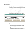
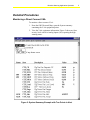
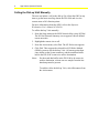
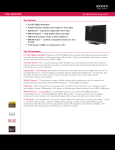
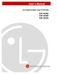
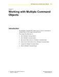
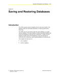
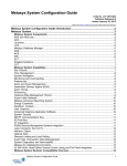
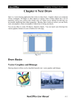
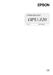
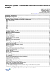
Issue Date 0401 TECHNICAL BULLETIN Vibration Alarming Application Operation Vibration Alarming Application Operation .........................................3 Introduction......................................................................................................... 3 Key Concepts...................................................................................................... 4 COS Messages ...............................................................................................................4 Detailed Procedures........................................................................................... 5 Monitoring a Direct Connect VAA ....................................................................................5 Calling the Dial-up VAA Manually ....................................................................................6 Formatting Trend Data ....................................................................................................7 Configuring Metasys Report Destinations........................................................................8 Troubleshooting ............................................................................................... 10 © 2001 Johnson Controls, Inc. Code No. LIT-1159400 www.johnsoncontrols.com 2 App. Notes: Operator Devices Vibration Alarming Application Operation 3 Vibration Alarming Application Operation Introduction The Vibration Alarming Application (VAA) is a continuously monitoring surveillance system that detects excessive vibration in rotating machinery. It does not perform automatic equipment shutdown. In addition to describing how to read VAA Change-of-State (COS) messages at the Operator Workstation (OWS), this document describes how to: • monitor a direct connect VAA • call the dial-up VAA manually • format trend data • configure Metasys report destinations 4 App. Notes: Operator Devices Key Concepts COS Messages Change-of-State (COS) messages regarding VAA alarm levels display at the Metasys OWS. The COS messages are formatted by the Metasys Report Router feature and take the same form as any Metasys COS, except for the following: • The point description describes the rotating equipment. • The engineering units indicate the severity level. • The alarm message indicates a user-defined action statement. Figure 1 shows an example of an Alert COS with numbered callouts referring to the differences specific to the VAA. Refer to Table 1 for an explanation of the numbered callouts. Figure 1: COS Message Example Table 1: COS Message Callouts Callout Section Name Description 1 Point Description The point description (24 characters maximum) describes the manufacturer and type of machine monitored. The same point description is used for all four Binary Inputs (BIs) to report the severity level of the machine. 2 Engineering Unit The State1 engineering unit (6 characters maximum) describes the severity level: Danger, Alarm, Alert. The State0 engineering unit describes the Accept level. 3 Alarm Message The user-defined alarm message (256 characters maximum) provides an operator or technician with the corrective action steps, if any, to perform. Use the definitions in the Vibration Severity Levels table of the Vibration Alarming Application Overview Technical Bulletin as guidelines for writing alarm messages. Note: One alarm message per severity level is allowed. Vibration Alarming Application Operation Detailed Procedures Monitoring a Direct Connect VAA To monitor a direct connect VAA: 1. From the OWS Network Map, open the System summary containing the VAA equipment points. 2. View the VAA equipment information. Figure 2 shows an Alert severity level with two Analog Inputs (AIs) reporting the high warning status. Figure 2: System Summary Example with Two Points in Alert 5 6 App. Notes: Operator Devices Calling the Dial-up VAA Manually The user can initiate a call to the dial-up VAA from the OWS at any time to get the latest trend log data in the DX-9100 and view the current status of all vibration points. For more information about the OWS, refer to the Operator Workstation User's Manual (FAN 634). To call the dial-up VAA manually: 1. From the Setup menu on the OWS Network Map, select N2 Dial. The N2 Dial Network Summary screen appears with all defined remote networks. 2. Highlight the remote site to call. 3. From the Action menu, select Dial. The N2 Dial screen appears. 4. Click Dial. This requests the selected local N2 Dialer Module (NDM) system to call the dial-up VAA. All remote points then come online on the System summary, and the trend data buffer held in the DX-9100 is sent to its archive destination. Notes: For the trend data buffer in the DX-9100 to be sent to its archive destination, at least one new sample from the last data dump must be present. To end the call to the dial-up VAA, select Disconnect from the Action menu. Vibration Alarming Application Operation Formatting Trend Data Note: The DX-9100 uses dBase Inc.’s dBASE III (.dbf file) format to store trended values. This is the same format used by the Metasys Point History feature. To format trend data: 1. Open the .dbf file using Microsoft Excel software. 2. Reformat and graph the data using only the FPVALUE, DATE_NDX, and TIME_NDX columns. As an option, download the Graph-It macro from The Advisor > Engineering/Technical > Predictive Diagnostics > Vibration Alarm App. This macro reformats and graphs the data. Note: The Graph-It macro is not supported or updated by Johnson Controls Inc. 7 8 App. Notes: Operator Devices Configuring Metasys Report Destinations To store trend data from the DX-9100 at an OWS, define a Personal Computer (PC) file destination under the appropriate report/access group. This is required for either the direct connect or dial-up VAA. The direct connect VAA archives history data stored by the Metasys Point History feature, and the dial-up VAA archives history data stored by the DX-9100 Trend Log feature. For more information about defining destinations for report/access groups, refer to the Operator Workstation User’s Manual (FAN 634). To configure Metasys report destinations: 1. When defining the PC file, check History under the Report types section. This is done because the DX-9100 trend data is linked to the Metasys Point History feature. Figure 3 shows an example of a PC file destination called REMOTE3 being defined on OWS1. Figure 3: PC File Destination Definition Example 2. Make sure the report access group chosen is under the same system as the vibration objects. Figure 4 shows an example of a group called REMOTE4 defined on Metasys OWS1. Vibration Alarming Application Operation 9 Figure 4: Report Access Group Definition Example IMPORTANT: For the dial-up VAA version, the Metasys OWS containing the PC file defined to store the remote DX-9100 trend data must be online at all times. If the OWS is offline at the time the trend upload occurs, the samples from the DX-9100 cannot transfer to the PC’s hard drive and will be lost. Therefore, as a precaution for dialup VAA installations, define a redundant PC file destination on a different OWS on the Metasys network. This second destination will save the same data as the primary PC file, but will be needed only if the upload to the primary PC file fails. 10 App. Notes: Operator Devices Troubleshooting Table 2: VAA Operation Troubleshooting Problem Resolution Workstation does not allow adjustment of setpoints or differentials of the Vibration CS object. The Adjust parameter for the Control System Analog Data (CSAD) point in the Control System (CS) model that the Vibration CS object references is set to N (No). Change it to Y (Yes). For a dial-up VAA, no trend data exists for the monitored vibration point. The point is not configured for trending under the Trend Log block of the downloaded GX program. Configure the point for trending and re-download the DX-9100 with the revised GX-9100 program. A vibration point continually goes into and out of alarm. First, make sure the setpoints and differentials for the three alarm limits and the Accept limit are set according to PDT recommendations. Second, consider increasing the default filter constant value of ten seconds for the vibration point in the GX-9100 program. This requires editing the downloaded program and then re-downloading it to the DX-9100. Third, with approval from the PDT, increase the Alarm thresholds and/or differentials slightly. The alarm sequencing does not occur per the literature. Make sure the Alert setpoint and differential match the Accept setpoint and differential per vibration point monitored. A vibration point is reporting a negative or very high value. Make sure the accelerometer is installed correctly and securely. Make sure all wire connections are tight and of the correct polarity. Make sure the vibration point AI is set for 4-20 mA in the downloaded GX-9100 program. Make sure the AI jumper on the DX-9100 is set to receive a 0-20 mA signal. Make sure the AI high and low range values in the downloaded GX-9100 program are correct for the signal conditioner you are using. Normally, the range is 0.0 to 1.0 inches per second (ips). Make sure the selected signal conditioner is ranged properly for the equipment being monitored. For assistance, contact the Predictive Diagnostics Team, 1-888-281-3792. The alarm light on the DX-9100 is on, but no vibration point is reporting an alarm. Check the configuration of the vibration point in the GX-9100 program to verify it is matched with its corresponding definition in the Metasys database. In particular, the High Limit value for the point defined in the GX-9100 program and the High Alarm Limit defined for the point in the Metasys database must match. Once they do, the alarm light will go on when the point is at an Alarm severity level. The value the vibration point is reporting never changes. For example, a value of 1.124 ips is being reported at all times. Properly configure the signal conditioner for the accelerometer. A signal conditioner sized for 0-1 ips, but connected to an accelerometer intended to report g’s, causes this problem Note: For additional troubleshooting information, refer to FAQ (Frequently Asked Questions) on The Advisor > Engineering/Technical > Predictive Diagnostics > Vibration Alarm App. Vibration Alarming Application Operation Notes 11 12 App. Notes: Operator Devices Notes Controls Group 507 E. Michigan Street P.O. Box 423 Milwaukee, WI 53201 www.johnsoncontrols.com Printed in U.S.A.