1
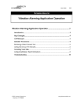
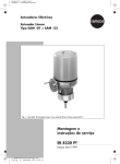
Series 290
Type 3291-1 and Type 3291-7
Pneumatic Control Valves
Fig. 1 · Type 3291-1 Control Valve
Mounting and
Operating Instructions
EB 8072 EN
Edition November 2011
Contents
Contents
1
General safety instructions . . . . . . . . . . . . . . . . . . . . . . . 4
2
2.1
Design and principle of operation. . . . . . . . . . . . . . . . . . . . 5
Transportation and storage . . . . . . . . . . . . . . . . . . . . . . . 5
3
3.1
Assembling valve and actuator. . . . . . . . . . . . . . . . . . . . . . 7
Assembly and adjustment . . . . . . . . . . . . . . . . . . . . . . . . 7
3.2
Pretensioning springs in actuator version "Actuator stem extends". . . . . 8
3.3
3.3.1
3.3.2
Valve and actuator with different rated travels . . . . . . . . . . . . . . 8
Actuator version "Actuator stem extends" . . . . . . . . . . . . . . . . 8
Actuator version "Actuator stem retracts" . . . . . . . . . . . . . . . . 10
4
4.1
Installation . . . . . . . . . . . . . . . . . . . . . . . . . . . . . . 11
Mounting position . . . . . . . . . . . . . . . . . . . . . . . . . . . 11
4.2
Piping design . . . . . . . . . . . . . . . . . . . . . . . . . . . . . 11
4.3
Valve insulation . . . . . . . . . . . . . . . . . . . . . . . . . . . . 11
4.4
Signal pressure line . . . . . . . . . . . . . . . . . . . . . . . . . . 11
4.5
Strainer and bypass . . . . . . . . . . . . . . . . . . . . . . . . . . 12
4.6
Test connection . . . . . . . . . . . . . . . . . . . . . . . . . . . . 12
5
Operation. . . . . . . . . . . . . . . . . . . . . . . . . . . . . . . 13
6
6.1
6.1.1
6.1.2
6.1.3
6.2
6.2.1
6.2.2
6.2.2.1
6.2.2.2
6.2.3
6.2.4
6.2.5
6.2.5.1
6.2.5.2
6.2.5.3
Maintenance – Replacing parts . . . . . . . . . . . . . . . . . .
General . . . . . . . . . . . . . . . . . . . . . . . . . . . . .
Sealing surfaces . . . . . . . . . . . . . . . . . . . . . . . . .
Measuring equipment . . . . . . . . . . . . . . . . . . . . . .
Lubricant . . . . . . . . . . . . . . . . . . . . . . . . . . . .
Replacing parts of standard version/version with extension bonnet
Removing the actuator . . . . . . . . . . . . . . . . . . . . . .
Packing and plug . . . . . . . . . . . . . . . . . . . . . . . .
Disassembly . . . . . . . . . . . . . . . . . . . . . . . . . . .
Assembly . . . . . . . . . . . . . . . . . . . . . . . . . . . .
Seat and/or seat retainer/flow divider St I . . . . . . . . . . . .
Disassembly . . . . . . . . . . . . . . . . . . . . . . . . . . .
Assembly . . . . . . . . . . . . . . . . . . . . . . . . . . . .
Height H1 . . . . . . . . . . . . . . . . . . . . . . . . . . . .
Gasket height H2 . . . . . . . . . . . . . . . . . . . . . . . .
Spacer ring . . . . . . . . . . . . . . . . . . . . . . . . . . .
2
EB 8072 EN
.
.
.
.
.
.
.
.
.
.
.
.
.
.
.
.
.
.
.
.
.
.
.
.
.
.
.
.
.
.
.
.
.
.
.
.
.
.
.
.
.
.
.
.
.
.
.
.
13
13
14
15
15
15
15
16
16
16
16
16
17
18
19
20
Contents
6.2.5.4
6.2.5.5
6.2.5.6
6.2.5.7
6.2.5.8
6.3
6.3.1
6.3.2
6.3.2.1
6.3.2.2
6.3.2.3
6.3.2.4
6.3.3
6.3.3.1
6.3.3.2
6.3.3.3
6.3.3.4
6.3.3.5
6.4
Bonnet gasket . . . . . . . . . .
Plug. . . . . . . . . . . . . . .
Bonnet . . . . . . . . . . . . .
Packing . . . . . . . . . . . . .
Threaded bushing . . . . . . . .
Valves with bellows section. . . .
Removing the actuator . . . . . .
Disassembly . . . . . . . . . . .
Bellows seal . . . . . . . . . . .
Plug. . . . . . . . . . . . . . .
Bellows bonnet . . . . . . . . .
Plug stem with bellows . . . . . .
Assembly . . . . . . . . . . . .
Bellows section . . . . . . . . .
Bellows bonnet . . . . . . . . .
Plug for version with bellows seal.
Bellows section with plug. . . . .
Additional assembly instructions .
Balanced valves . . . . . . . . .
.
.
.
.
.
.
.
.
.
.
.
.
.
.
.
.
.
.
.
.
.
.
.
.
.
.
.
.
.
.
.
.
.
.
.
.
.
.
.
.
.
.
.
.
.
.
.
.
.
.
.
.
.
.
.
.
.
.
.
.
.
.
.
.
.
.
.
.
.
.
.
.
.
.
.
.
.
.
.
.
.
.
.
.
.
.
.
.
.
.
.
.
.
.
.
.
.
.
.
.
.
.
.
.
.
.
.
.
.
.
.
.
.
.
.
.
.
.
.
.
.
.
.
.
.
.
.
.
.
.
.
.
.
.
.
.
.
.
.
.
.
.
.
.
.
.
.
.
.
.
.
.
.
.
.
.
.
.
.
.
.
.
.
.
.
.
.
.
.
.
.
.
.
.
.
.
.
.
.
.
.
.
.
.
.
.
.
.
.
.
.
.
.
.
.
.
.
.
.
.
.
.
.
.
.
.
.
.
.
.
.
.
.
.
.
.
.
.
.
.
.
.
.
.
.
.
.
.
.
.
.
.
.
.
.
.
.
.
.
.
.
.
.
.
.
.
.
.
.
.
.
.
.
.
.
.
.
.
.
.
.
.
.
.
.
.
.
.
.
.
.
.
.
.
.
.
.
.
.
.
.
.
.
.
.
.
.
.
.
.
.
.
.
.
.
.
.
.
.
.
.
.
.
.
.
.
.
.
.
.
.
.
.
.
.
.
.
.
.
.
.
.
.
.
.
.
.
.
.
.
.
.
.
.
.
.
.
.
.
.
.
.
.
.
.
.
.
.
.
.
.
.
.
.
.
.
.
.
.
.
.
21
21
22
23
23
24
24
24
24
24
25
25
26
26
26
27
28
28
29
7
7.1
Appendix . . . . . . . . . . . . . . . . . . . . . . . . . . . . . . . 29
Tools . . . . . . . . . . . . . . . . . . . . . . . . . . . . . . . . . 29
7.2
Tightening torques (1120-1400) . . . . . . . . . . . . . . . . . . . . 29
7.3
Spacer rings (1120-3074) . . . . . . . . . . . . . . . . . . . . . . . 30
8
8.1
Description of nameplates . . . . . . . . . . . . . . . . . . . . . . . 30
Type 3291 Valve . . . . . . . . . . . . . . . . . . . . . . . . . . . 30
8.2
Type 3277 Actuator . . . . . . . . . . . . . . . . . . . . . . . . . . 31
8.3
Type 3271 Actuator . . . . . . . . . . . . . . . . . . . . . . . . . . 31
9
Customer inquiries . . . . . . . . . . . . . . . . . . . . . . . . . . 32
10
Dimensions and weights. . . . . . . . . . . . . . . . . . . . . . . . 32
Note: Non-electrical actuators and valves do not have their own potential ignition source
according to the risk assessment in the rare incident of an operating fault, corresponding to
EN 13463-1: 2001 paragraph 5.2, and therefore do not fall within the scope of the
European Directive 94/9/EC.
EB 8072 EN
3
General safety instructions
1
General safety instructions
4 The control valve must only be mounted, started up or serviced by fully
4
4
4
4
trained and qualified personnel, observing the accepted industry codes and
practices. Make sure employees or third persons are not exposed to any
danger. All safety instructions and warnings in these mounting and operating instructions, particularly those concerning assembly, start-up and maintenance, must be observed.
The control valves fulfill the requirements of the European Pressure Equipment Directive 97/23/EC. Valves with a CE marking have a declaration of
conformity that includes information about the applied conformity assessment procedure.
For appropriate operation, make sure that the control valve is only used in
areas where the operating pressure and temperatures do not exceed the operating values which are based on the valve sizing data submitted in the order. The valve must be given adequate time to warm up or cool down according to the prevailing ambient and operating conditions. The manufacturer does not assume any responsibility for damage caused by external
forces or any other external influence!
Any hazards which could be caused in the control valve by the process medium, operating pressure, signal pressure or by moving parts are to be prevented by means of the appropriate measures.
Proper shipping and appropriate storage of the control valve are assumed.
CAUTION!
4 For installation and maintenance work on the valve, make sure the relevant
4
4
4
EB 8072 EN
section of the pipeline is depressurized and, depending on the process medium, drained as well. If necessary, allow the control valve to cool down or
warm up to reach ambient temperature prior to starting any work on the
valve.
Prior to performing any work on the valve, make sure the supply air and
control signal are disconnected or blocked to prevent any hazards that could
be caused by moving parts.
Special care is needed for pneumatic control valves when the actuator
springs are pretensioned. These actuators are labeled correspondingly and
can also be identified by three long bolts protruding from the bottom of the
actuator. Prior to starting any work on the control valve, relieve the compression from the pretensioned springs.
Design and principle of operation
2
Design and
operation
principle
of
The Type 3291-1 and Type 3291-7 Pneumatic Control Valves consist of the
Type 3291 Globe Valve with clamped-in
seat combined with either a Type 3271 or a
Type 3277 Pneumatic Actuator with integral
positioner and/or limit switch attachment.
The process medium flows through the valve
in the direction indicated by the arrow. The
position of the plug determines the flow rate
across the seat. Its position is determined by
changes in the signal pressure acting on the
actuator diaphragm.
The plug stem is connected to the diaphragm
stem by the stem connector. The stems are
sealed by a spring-loaded PTFE V-ring
packing or an adjustable high-temperature
(HT) packing.
Fail-safe position
Depending on how the springs are arranged
in the actuator, the control valve assumes
one of two different fail-safe positions:
Actuator stem extends:
When the pressure is reduced or the supply
air fails, the actuator springs move the actuator stem downwards and close the valve.
The valve opens when the signal pressure
rises opposing the force of the springs.
Actuator stem retracts:
When the pressure is reduced or the supply
air fails, the actuator springs move the actuator stem upwards and open the valve.
The valve closes when the signal pressure
rises opposing the force of the springs.
2.1
Transportation and storage
These instructions provide information on the
correct handling of valves during transportation, storage and hoisting.
NOTICE
Do not lift the control valve assembly using
the actuator's lifting ring. This lifting ring is
only intended for lifting the actuator without
the valve.
Attach the lifting support to the valve body.
4 Leave control valves in their transport
container or on the pallet as long as possible.
4 Store valves in a dry place until installation.
4 The transport and storage temperature
for valves must be kept between –20 and
65 °C.
4 Protect the valves (especially the dia-
phragm stem) against knocks and vibrations etc.
4 Any damage to corrosion protection
(paintwork, oiled surfaces etc.) must be
remedied immediately
4 Always wear protective gloves, clothing
and eyewear when performing any work
on the valve.
4 Never leave the load suspended in
mid-air.
4 Prior to lifting any valve, always check
the weight of the load in SAMSON's
technical documentation.
4 Always use lifting equipment according
to the actual load of the lifting goods.
EB 8072 EN
5
Design and principle of operation
4 Carefully lift the load off the ground and 4 Remove the protective caps from the
check that all lifting supports are securely
attached and that the control valve is well
balanced.
4 Lift the control valve in the position in
which it will be installed.
valve inlet and outlet shortly before installing the valve in the pipeline.
4 Make sure that the control valve is properly installed before removing the lifting
supports.
4 Lift the control valve at its center to pre-
4 Refer to the diagram showing how a
4 For valves weighing over 25 kg, make
4 Attach the slings around the valve body.
vent it from tipping to one side.
sure that mounting rings for chain hoists
are fitted at an adequate height above
the installation site. Often, it is recommendable to use sliding rails or swivel
arms with a hoist.
Fig. 2 · Safe lifting of the valve
6
EB 8072 EN
valve can be lifted at the installation site.
To keep the valve in the upright position
and to prevent it from tipping, attach a
sling to the lifting ring of the actuator.
Assembling valve and actuator
3
Assembling valve and actuator
Instead of a simple pneumatic actuator, the
valve can be operated by a pneumatic actuator with additional handwheel or by an
electric actuator.
The standard pneumatic actuator can be replaced with a larger or smaller actuator for
all valve sizes.
If the travel range of the actuator is larger
than that of the valve, the actuator springs
are preloaded by the manufacturer so that
the travels match.
Each valve is supplied with parts required
for a standard valve. If another actuator is to
be mounted on the valve, the mounting parts
must be ordered together with the actuator.
Refer to the documents 1600-0501 to
1600-0550 to find out which parts are required. The originally used parts must then
be replaced by the additionally ordered
parts.
3.1
Assembly and adjustment
If the valve and actuator have not been
pre-assembled by the manufacturer, or if the
actuator of a valve is to be replaced by an
actuator of another type or another size,
proceed as described below:
1. Undo the lock nut (10) and stem connector nut (9).
Firmly press the plug (5) together with
the plug stem into the seat (4). Thread
the stem connector nut (9) and lock nut
(10) downwards.
2. Remove stem connector clamps (A27)
and unscrew nut (A8) from the actuator.
Slide the nut over the plug stem (mount
dust sleeve, if necessary).
3. Place actuator onto the yoke (3) and secure with the nut (A8).
4. Read bench range (or bench range with
preloaded springs) and fail-safe action
from the actuator's nameplate (e.g. 0.2
to 1 bar and "Actuator stem extends").
The lower value of the bench range
(0.2 bar) corresponds to the lower bench
range value to be adjusted, while the upper
bench range value (1 bar) corresponds to
the upper bench range value. The fail-safe
action "Actuator stem extends" (FA) or "Actuator stem retracts" (FE) is indicated on the
Type 3271 and Type 3277 Actuator by the
corresponding symbol.
5. For actuators with "Actuator stem extends", apply a signal pressure to the
bottom diaphragm chamber which corresponds to the lower bench range value
(e.g. 0.2 bar).
For actuators with "Actuator stem retracts", apply a signal pressure to the
top diaphragm chamber which corresponds to the upper bench range value
(e.g. 1 bar).
6. Thread the stem connector nut (9) by
hand until it touches the actuator stem
(A7). Then, turn it another ¼ turn and
secure this position with the lock nut
(10).
7. Position the stem connector clamps
(A27) and fasten. Align the travel indicator scale (83) with the tip of the stem
connector.
EB 8072 EN
7
Assembling valve and actuator
Note on disassembling the actuator
Before disassembling an actuator with
fail-safe action "Actuator stem extends" and
particularly an actuator with preloaded
springs, apply a pressure to the signal pressure connection (S) that slightly exceeds the
lower bench range value (see nameplate of
the actuator) to allow the nut (A8) to be
undone.
3.2
Pretensioning springs in
actuator version "Actuator
stem extends"
To achieve a greater positioning force, the
springs in actuators with "Actuator stem extends" can be preloaded with up to 25 % of
their travel or bench range.
If the springs are preloaded with, for example, 0.1 bar for a bench range of 0.2 to
1 bar, the bench range is shifted by 0.1 bar
to result in a bench range of 0.3 to 1.1 bar
(0.1 bar corresponds to a preload of
12.5 %).
When adjusting the valve, the lower bench
range is to be set to 0.3 bar. Make sure the
new bench range of 0.3 to 1.1 bar is indi-
Legend for Fig. 3
1
Valve body
2
Bonnet
3
Yoke
4
Seat
5
Plug
7
Guide bushing
8
Threaded bushing
9
Stem connector nut
10
Lock nut
13
Stud bolt
8
EB 8072 EN
14
15
17
83
92
124
125
126
127
cated on the nameplate as the bench range
with preloaded springs!
3.3
Valve and actuator with
different rated travels
3.3.1 Actuator version "Actuator
stem extends"
NOTICE
Valves that have a travel smaller than the
rated travel of the actuator always need to
use preloaded springs.
Example:
Valve with 30 mm rated travel and
1400 cm² actuator with 60 mm rated travel,
0.4 to 2 bar bench range.
1. Set the signal pressure to 1.6 bar. This
pressure is slightly higher than the signal
pressure of 1.2 bar required for
tensioning the springs (1.2 to 2 bar
range) which corresponds to half the actuator travel (30 mm).
2. Thread stem connector nut (9) until it
touches the actuator stem (A7).
Nut
Packing
Gasket
Travel indicator scale
Nut
Seat retainer
Spacer ring
Gasket
Gasket
Actuator
A1
Top diaphragm case
A2
Bottom diaphragm
case
A4
Diaphragm
A7
Diaphragm stem
A8
Nut
A16
Venting
A27
Stem connector clamp
S
Signal pressure
connection
Assembling valve and actuator
A16
A1
A4
S
A8
A2
A7
3
83
A27
9
92
10
17
8
15
125
13
14
126
2
124
7
1
5
4
127
Fig. 3 · Type 3291-1 Control Valve
EB 8072 EN
9
Assembling valve and actuator
3. Secure the position with lock nut (10)
and attach stem connector as described
in section 3.1.
4. Enter the 1.6 to 2.4 bar bench range
valid for the mounted valve on the
nameplate of the actuator.
3.3.2 Actuator version "Actuator
stem retracts"
Note: The springs in the actuator version
"Actuator stem retracts" cannot be preloaded!
If a valve is to be attached to a larger actuator (rated travel of actuator larger than the
rated travel of the valve), only the first half
of the bench range of the actuator can be
used.
Example:
Valve with 30 mm rated travel and
1400 cm² actuator with 60 mm rated travel,
0.2 to 1 bar bench range:
A useable bench range of 0.2 to 0.6 bar is
available for the half valve range.
10
EB 8072 EN
CAUTION!
Actuators which have been
preloaded by the manufacturer without an attached valve are marked by
a label.
In addition, you will notice three extended bolts on the bottom diaphragm case. They enable you to
evenly relieve the compressed
springs when disassembling the actuator.
Installation
4
Installation
4.3
Valve insulation
NOTICE
The valve must be installed with the least
amount of vibrations possible and without
any stress.
Control valves with bellows seal or extension
bonnet can only be insulated up to the bonnet flange of the valve body when the medium temperature is below 0 °C or above
220 °C.
4.1
Valves used in applications according to
NACE MR 0175, NACE MR 0103 or
ISO 15156 must not be insulated.
Mounting position
The valve can be mounted in any desired
position. However, vertical installation with
the actuator pointing upwards is preferable
for valves in NPS 4 and larger to facilitate
maintenance.
For valves with extension bonnet or bellows
seal, or for actuators weighing more than
50 kg, mount a suitable support or suspension for the actuator.
4.2
Piping design
4.4
Signal pressure line
Connect the signal pressure line to the bottom diaphragm case for valves with actuator
version "Actuator stem extends" and to the
top diaphragm case for valves with actuator
version "Actuator stem retracts".
The bottom signal pressure connection of the
Type 3277 Actuator is located at the side of
the yoke of the bottom diaphragm case.
To allow the control valve to work properly,
the pipeline upstream of the valve must be
straight and free of obstructions for a length
twice to 10 times of the pipe diameter (NPS)
and the pipeline downstream of the valve for
a length at least 4 to 20 times of the pipe diameter (NPS), depending on the process
conditions or for process media containing
solids.
Contact SAMSON if this length cannot be
met during installation.
Clean out the pipeline thoroughly prior to installing the valve.
Fig. 4 · Type 3277 with signal pressure connection
at the side for "Actuator stem extends"
EB 8072 EN
11
Installation
4.5
Strainer and bypass
We recommend installing a strainer upstream of the valve body.
We also recommend installing a shut-off
valve both upstream of the strainer and
downstream of the valve as well as laying a
bypass so that you do not need to shut down
the plant for maintenance.
4.6
Test connection
A test connection at the top flange of a valve
version with bellows seal allows the bellows
seal to be monitored for leaks.
Particularly for liquids and vapors, we recommend installing a suitable leak indicator
at the test connection, such as a contact
pressure gauge, an outlet into an open vessel or an inspection window.
Fig. 5 · Test connection above the bellows seal
12
EB 8072 EN
Operation
5
Operation
(e.g. reversing the fail-safe action of the actuator etc.)
For details, refer to Mounting and Operating Instructions
EB 8310 EN for Type 3271 and
EB 8311 EN for Type 3277
6
Maintenance – Replacing parts
The control valve is subject to natural wear,
especially at the seat, plug and packing.
Depending on the application, the valve
needs to be checked regularly to prevent
against possible failures.
6.1
General
If leakage occurs, this could be caused by a
damaged packing or a defective bellows
seal.
If the valve does not seal properly, the tight
shut-off may be impeded by dirt or other impurities caught between the seat and plug,
or by damaged seating surfaces.
Remove the parts, clean them thoroughly
and replace them with new ones, if necessary.
CAUTION!
Before servicing or disassembling the control
valve, depressurize the concerned section of
the plant and drain it, if necessary, depending on the medium used.
Wait until the valve cools down to ambient
temperature if the process medium is hot.
As valves are not free of cavities, beware
that there might still be residual medium in
the valve.
This applies, in particular, for valve versions
with extension bonnet and bellows seal.
We recommend removing the valve from the
pipeline.
EB 8072 EN
13
Maintenance – Replacing parts
NOTICE
On performing any work on the valve, first
shut off the signal pressure, disconnect the
signal pressure line and remove the actuator.
Note: When mounting the valve bonnet, the
large port of the V-port plug and one of the
openings of the seat retainer must face the
valve outlet.
DF 10
6.1.1 Sealing surfaces
Make sure all sealing surfaces of the valve
(DF 1 to DF 10) are clean.
Check that newly inserted gaskets are undamaged, free of burrs from punching and
properly seated.
DF 8 und 9
DF 5
If new spacer rings are required, they must
also be free of burrs and flat.
DF 4
Note: Only one spacer ring (125) and one
gasket (126) may be used for valves up to
NPS 4 for height compensation.
Several spacer rings (125) and gaskets
(126) can be used for valves in NPS 6 or
larger. The rings and gaskets must be installed in alternating sequence.
yyy
yy
yyy
DF 3
DF 7
DF 2
NOTICE
To prevent damage to the internal parts,
sealing surfaces and threads, proceed carefully while assembling or disassembling the
valve.
During all work performed on the valve,
strictly observe the specified tightening
torques in Table 5 (according to document
1120-1400).
14
EB 8072 EN
DF 1
Fig. 6 · Sealing surfaces DF 1 to DF 10
DF 6
Maintenance – Replacing parts
6.1.2 Measuring equipment
To measure the heights, only use measuring
equipment that remains aligned at an angle
to the dimension to be measured. Appropriate measuring equipment includes, for example, a dial indicator gauge with magnetic
base, vernier depth gauge or depth gauge
with bridge.
To measure the gaskets, a caliper may also
be used, provided the wider jaws (and not
the blades) are used for measuring. Make
absolutely sure that no pressure is exerted
on the gasket to prevent the gasket from becoming deformed.
6.1.3 Lubricant
Note: Contact your nearest SAMSON subsidiary or the SAMSON After-sales Service
department for information on suitable lubricants.
Apply a suitable lubricant to the plug stem
(5) in area where the PTFE packing is located as well as to the individual parts of the
PTFE packing (15). In valves with balanced
plugs, additionally apply lubricant to the
pressure balancing sleeve and the bearing
strip.
Note: Do not apply lubricant to the packing
parts or plug stem when a graphite packing
is used. Similarly, do not apply lubricant to
the pressure-balancing sleeve or bearing
strip when graphite pressure-balancing
parts are used in the valve.
For corrosion protection and friction reduction, apply a suitable grease to the following
parts:
Threads of the bolts (13, 32), threads and
bearing face of the nuts (14, 33), thread
and sealing surface of the threaded bushing
(8), threads of the stem connector nut (9)
and lock nut (19), threads and screw head
faces of the pressure-balancing assembly.
6.2
Replacing parts of standard
version/version with
extension bonnet
The instructions below describe the procedure for the standard version with bonnet
(2). The same procedure applies to the version with extension bonnet (21).
6.2.1 Removing the actuator
The actuator and yoke must be removed to
perform maintenance or repair on the valve.
Pneumatic actuator with fail-safe action
"Actuator stem extends"
1. Remove clamp (A27).
2. Apply a pressure to the bottom signal
pressure connection that slightly exceeds
the lower bench range value (see nameplate). As a result, the actuator stem lifts
off the plug stem, making the actuator
stem line free of tension.
3. Undo nut (92) and lift the actuator together with yoke off the valve.
Pneumatic actuator with fail-safe action
"Actuator stem retracts"
Proceed in the same manner as described
for actuator with fail-safe action "Actuator
EB 8072 EN
15
Maintenance – Replacing parts
stem extends". However, pressure does not
need to be applied to the signal pressure
connection.
6.2.2 Packing and plug
If the process medium leaks from the
threaded bushing (8), this means the packing is leaking.
A damaged or blocked PTFE packing must
be replaced.
If a high-temperature (HT) packing is installed, the threaded bushing (8) can be
slightly retightened to stop the packing from
leaking.
As soon as the valve leaks constantly, check
the plug and seat. Clean, machine or replace the plug and seat as required.
6.2.2.1 Disassembly
1. Remove threaded bushing (8) and nuts
(14) from the bonnet (2).
2. Carefully lift the bonnet (2) with plug (5)
and the plug stem off the body (1).
3. Unscrew stem connector nut (9) and lock
nut (10) from the plug stem.
4. Pull the plug together with plug stem
from underneath out of the bonnet.
Carefully check the sealing surface.
Note: The plug must be replaced if any
slight damage to the seating surface cannot
be removed by machining.
5. Use a packing tool to pull all the packing
parts (PTFE V-rings, washers, bushing,
16
EB 8072 EN
spring) upwards out of the packing
chamber. Carefully clean the packing
chamber.
6. Check the parts for damage. Replace
any damaged parts.
6.2.2.2 Assembly
Note: Prior to mounting the plug, bonnet
and packing, renew all gaskets (127, 126,
17) at the seat (4) and seat retainer (124).
For this, you need to determine again the required thickness of the spacer ring (up to
NPS 4) or spacer rings (NPS 6 or higher).
6.2.3 Seat and/or seat
retainer/flow divider St I
If parts, such as the seat or seat retainer,
have been replaced with new ones due to
leakage or wear, we recommend replacing
the packing at the same time (see
section 6.2.2.1).
The flow divider St I is used instead of the
seat retainer (124) in versions with flow divider. The procedure to assemble or disassemble the valve is performed in the corresponding manner.
6.2.4 Disassembly
1. Unthread nut (14).
2. Carefully lift the bonnet (2) with plug (5)
and the plug stem out of the body (1).
3. Remove all the parts from inside the
valve body and place them in order on a
flat surface:
- Gasket (17)
Maintenance – Replacing parts
- Spacer ring(s) (125)
- Gasket(s) (126)
- Seat retainer (124) or flow divider St I
- Seat (4)
- Gasket (127)
4. Clean spacer ring(s), seat retainer and
seat. Check these parts for damage.
Machine or replace the seat retainer and
seat, if necessary.
of the seat bridge. Make absolutely sure
that the seating surface and mating surface do not get damaged.
The seat has a clear amount of clearance within the seat bridge and is
aligned centrally to the valve body's
neck.
1
4
Note: First determine the required thickness
of the spacer ring(s). Only after this, it is
possible to know whether they can be
reused. The gaskets must be replaced at any
rate.
127
Fig. 8 · Installing the seat (4)
6.2.5 Assembly
Note: When assembling internal parts, read
the instructions concerning the sealing surface (section 6.1.1) and measuring equipment (section 6.1.2).
1. Insert new gasket (127) of the seat
bridge.
2. Carefully place the seat (4) through the
valve body's neck onto the gasket (127)
3. Insert the seat retainer (124) into the
body as centrally as possible. Otherwise, it may get stuck in the area of the
valve body's neck. If it does get stuck,
the seat retainer can be aligned centrally
using a soft rubber hammer until it is further inserted into the body.
Carefully insert the seat retainer into the
seat, aligning the seat centrally.
To check whether the seat retainer sits correctly on the seating surface, slightly lift and
lower the seat retainer.
124
1
1
127
4
127
Fig. 7 · Gasket (127) for seat bridge
Fig. 9 · Installing the seat retainer (124)
EB 8072 EN
17
Maintenance – Replacing parts
2. Write the values 1 to 3 down in Table 1
in the appropriate columns. Calculate
the mean value of H1 from these values
and note it in the H1actual column.
Align the seat retainer so that one of its
openings faces the valve outlet.
6.2.5.1 Height H1
3. Calculate the difference ∆H between the
target height H1target and the actual
height H1actual and note it in the appropriate column.
H1
H1
To determine the height H1 between the inside seating surface (DF 3) of the seat retainer (124) and the outside seating surface
(DF 6) of the valve body (1), proceed as follows.
1
127
Fig. 11 · Detailed view of height H1
Fig. 10 · Determining the height H1
1. Measure height H1 at three locations
distributed evenly around the circumference of the valve body's neck.
Table 1 · Determining the height H1
NPS
H1target
[mm]
½ to 1
4.8
1½
5.1
2
5.1
3
5.1
4
5.1
18
6
9.9
8
10.1
EB 8072 EN
H1value 1
[mm]
H1value 2
[mm]
H1value 3
[mm]
H1actual
[mm]
∆H = H1target – H1actual
[mm]
Maintenance – Replacing parts
6.2.5.2 Gasket height H2
126
124
1
1. Prior to assembly, measure the height
H2actual of the new gasket (126, up to
NPS 4) or gaskets (126, NPS 6 or
larger) at three locations distributed
evenly around the circumference of the
valve body's neck.
H2
Fig. 13 · Inserting the gasket (126)
126
Note: For valves in NPS 6 or larger, gaskets
(126) and spacer rings (125) are inserted
into the groove of the seat retainer in alternating sequence.
Fig. 12 · Determining height H2 of gasket (126)
126
2. Write down the three values in Table 2
in the appropriate columns.
124
1
3. Calculate the mean value from these values and note it in the H2actual column.
4. Insert gasket (126) into the groove of the
seat retainer (124).
Fig. 14 · Exact position of the gasket (126)
Table 2 · Determining the height H2
Number of gaskets
(one gasket up to NPS 4
two gaskets from NPS 6)
H2value 1
[mm]
H2value 2
H2value 3
H2actual
[mm]
[mm]
[mm]
EB 8072 EN
19
Maintenance – Replacing parts
6.2.5.3 Spacer ring
1. Calculate the total height ttotal of the required spacer rings (125) using the previously measured values and write down
the result in Table 3 in the appropriate
column.
2. Select the spacer rings for the required
total height ttotal using the List of Accessories 1120-3074.
125
126
124
1
NOTICE
For height compensation, only one spacer
ring can be used for valves sizes up to
NPS 4. For valves in NPS 6 and larger, several spacer rings can be used as calculated
in Table 3 or from the valve parts list.
3. Carefully place the spacer ring (125)
onto the gasket (126) between the seat
retainer (124) and valve body (1).
For valves in NPS 6 and larger, place
the gasket (126) and spacer ring (125)
in alternating sequence until all the gaskets and spacer rings are installed.
Note: The spacer rings must not rest on any
part of the seating surface (DF 6) of the
valve body.
Fig. 15 · Spacer ring (125) on gasket (126)
Table 3 · Selecting the spacer ring
Height T
[mm]
Tolerance
[mm]
6.1 – ∆ – H2actual
– 0.1
1
12.1 – ∆ – H2actual_total
–0.1
2
NPS
Ideal height ttotal [mm]
Number of
spacer rings
½ to 1
1½
2
3
4
6
8
20
EB 8072 EN
Maintenance – Replacing parts
6.2.5.4 Bonnet gasket
6.2.5.5 Plug
1. Place gasket (17) into the groove of the
seat retainer and the body.
The gasket must not jut out over the seating
surface (DF 6) of the valve body (1).
17
125
126
1
124
Note: For valves with bellows section, the
bellows section (bonnet) and plug are
ready-assembled in one unit. Proceed as described in section 6.3.
1. Apply a suitable lubricant to the plug
stem (5) around the area where the PTFE
packing will be located.
2. Carefully insert the plug into the seat (4)
and align it so that the large port faces
the valve outlet (port that will be first to
release the flow rate when the valve
starts to stroke).
Fig. 16 · Gasket (17) on spacer ring (125)
Note: A slight height difference (S) exists between the bonnet gasket and the sealing surface of the valve body.
NOTICE
Do not apply any lubricant when a
high-temperature (HT) packing is used.
17
125
126
124
1
Fig. 18 · Inserting the plug (5)
Fig. 17 · Detailed view of bonnet gasket (27)
EB 8072 EN
21
Maintenance – Replacing parts
Table 4 · Tightening torques for nuts (14)
6.2.5.6 Bonnet
1. Carefully place bonnet over the plug
stem onto the bonnet gasket (17).
2. Apply a suitable lubricant to the threads
of the stud bolts (13) and nuts (14) as
well as to bearing face of the nuts.
NPS
Tightening torque [Nm]
Class 300
Class 600
60
60
½ to 1
1½
68
68
2
112
112
3
118
118
4
100
100
6
296
296
8
On req.
1040
Class 900
On request
2
17
1
6. Repeat this tightening procedure using
100 % of the specified tightening torque.
7. Finally, retighten all the nuts in clockwise
order with the full tightening torque one
last time.
Make sure the nuts are completely tightened and cannot be turned any further.
Fig. 19 · Mounting the bonnet (2)
3. Tighten the nuts in a criss-cross pattern
applying 50 % of the specified tightening torque.
4
6
1
2
5
7
Note: The gasket (126) under the spacer
ring yields, meaning tightening the nuts
once is not sufficient.
4. Repeatedly retighten the nuts with 50 %
of the specified tightening torque until
the nuts cannot be turned any further.
5. Repeat this tightening procedure using
75 % of the specified tightening torque.
22
EB 8072 EN
8
3
Fig. 20 · Tightening the nuts (14)
Maintenance – Replacing parts
6.2.5.7 Packing
1. Apply a suitable lubricant to the individual parts of the PTFE packing.
8
2. Carefully slide all the packing parts (15)
over the plug stem into the packing
chamber in the bonnet. Make absolutely
sure that they are inserted in the correct
order.
Note: The number of spacer bushings to be
used depends on the valve size (NPS) which
determines the size of the packing chamber.
15
6.2.5.8 Threaded bushing
1. Apply a suitable lubricant to the thread
and sealing surface of the threaded
bushing (8).
2. Slide threaded bushing over the plug
stem and screw it into the bonnet.
Note: When a high-temperature (HT) packing is used, only tighten the threaded bushing a little. If the medium leaks out at the
threaded bushing, you can retighten the
threaded bushing slightly.
3. When a PTFE packing is installed,
tighten the threaded bushing.
Mount the yoke and actuator as described in
section 3.1.
Fig. 21 · Packing (15) and threaded bushing (8)
EB 8072 EN
23
Maintenance – Replacing parts
6.3
Valves with bellows section
For valves with bellows section, the bellows
section containing the plug stem and bellows
is mounted as one unit.
6.3.1 Removing the actuator
Remove the actuator as described in section
6.2.1.
6.3.2 Disassembly
6.3.2.1 Bellows seal
1. Unscrew nut (14) and remove it.
2. Lift complete bellows section assembly
out of the body.
9
10
8
3. Clamp the bellows section in a suitable
apparatus to perform further work on it.
Do not apply a load to the bellows or
twist it.
15
101
42
39 (2x)
33
6.3.2.2 Plug
22
Valves up to NPS 1½
1. Place an open-end wrench on the flattened area of the plug stem to hold it
stationary and unscrew nut (6) from plug
(29).
37
2. Remove plug from hexagon end of the
plug stem.
14
17
6
4
29
Fig. 22 · Type 3291 with bellows section
24
EB 8072 EN
Fig. 23 · Plug for valves up to NPS 1½
Maintenance – Replacing parts
Valves in NPS 2 and larger
6.3.2.4 Plug stem with bellows
1. Bend back the edges of the lock plate
(31) from the heads of the screws (34).
1. Lift off top gasket (39).
2. Remove the screws (34).
3. Unscrew the plug (29) from the plug
stem and remove it.
34
2. Lift the plug stem/bellows assembly (37)
upwards out of the bellows section (22).
The second gasket (39) at the bottom is
now accessible.
31
27
28
101
Fig. 24 · Plug for valves in NPS 2 and larger
6.3.2.3 Bellows bonnet
1. Unthread stem connector nut (9) and
lock nut (10). Unscrew threaded bushing
(8).
2. Remove nuts (33) for bellows bonnet
(101).
DF 14
DF 13
39
37
DF 12
DF 11
39
22
3. Hold the plug stem stationary and lift off
the bellows bonnet.
4. If necessary, use a suitable tool to remove the packing.
Fig. 25 · Assembly consisting of plug stem and
bellows (37) and bellows bonnet (101)
EB 8072 EN
25
Maintenance – Replacing parts
surface (DF 12) of the bellows lies flat on
the gasket (39).
6.3.3 Assembly
Gaskets and sealing surfaces
Check gasket (39) and the sealing surface of
the bellows section (22), bellows bonnet
(101) and the plug stem/bellows assembly
(37) for damage. Renew them, if necessary.
3. Place the second gasket (39, top) flat on
the seating surface (DF 13) of the plug
stem/bellows assembly (37).
4. Apply a suitable lubricant to the area
what will later become the packing area.
6.3.3.1 Bellows section
6.3.3.2 Bellows bonnet
1. Insert the first gasket (39, bottom) into
the bellows section (22), making sure it
rests properly on the seating surface
(DF 11).
1. Carefully guide the bellows bonnet (101)
over the bellows/plug stem assembly.
Place the second gasket (39, DF 14) flat
on the seating surface.
2. Carefully insert the plug stem/bellows
assembly (37) from the top into the bellows section, making sure the seating
2. Apply a suitable lubricant to the thread
and sealing face of the threaded bushing (8). Screw it into the bonnet and
hand-tighten the bellows bonnet, so that
the plug stem with bellows (37) can still
turn.
3. Thread lock nut (10) onto the plug stem
(37) to protect the bellows against expanding too far.
101
DF 14
DF 13
39
37
DF 12
DF 11
39
22
Fig. 26 · Mounting the plug stem with bellows (37)
26
EB 8072 EN
4. Fasten the bellows bonnet (101) onto the
bellows section (22) using the nuts (33)
and bolts (32). Tighten nuts (33) only
slightly to allow the plug stem/bellows
assembly to still turn easily in ready-assembled state.
Maintenance – Replacing parts
6.3.3.3 Plug for version with
bellows seal
Use required tightening torques according to
document 1120-1400.
Valves in NPS 2 and higher
1. Screw plug (29) with associated washer
or lock plate (31) onto the plug stem.
Valves up to NPS 1½
2. Tighten screw (34) to fasten the plug
over the clamping washer (28) and
flange (27).
1. Thread nut (6) by hand as far as it will
go onto the plug stem (37).
3. Bend any edges of the lock plate (31)
over the heads of the screws.
2. Place plug (29) onto the hexagon end of
the plug stem.
3. Place an open-end wrench on the flattened area of the plug stem to hold it
stationary. Screw nut (6) onto plug.
6
34
31
27
28
Fig. 28 · Plug for valve in NPS 2 and higher
Note: Prior to mounting the bellows section
with plug, renew all gaskets and the spacer
rings. Refer to section 6.2.5.
Fig. 27 · Plug for valves up to NPS 1½
EB 8072 EN
27
Maintenance – Replacing parts
6.3.3.4 Bellows section with plug
1. Place the plug into the seat (4), making
sure that the large port of the plug faces
the valve outlet.
9
2. Place the bellows section on the body.
Make sure the gasket (17) does not
move.
10
8
15
3. Fasten the bellows bonnet with nuts (33).
101
4. Unthread lock nut (10) from the plug
stem and the threaded bushing (8) from
the bellows bonnet.
42
39 (2x)
33
6.3.3.5 Additional assembly
instructions
22
Proceed to assemble nuts (14), packing (15)
and threaded bushing (8) as described from
section 6.2.5.6 onwards.
37
14
17
4
29
Fig. 29 · Type 3291 with bellows seal
28
EB 8072 EN
Appendix
6.4
Balanced valves
The bonnet and plug of balanced valves are
assembled and disassembled in the same
manner as that of the valve with standard
V-port plug. Refer to section 6.2.2.1.
Any work on the plug itself must be
performed by SAMSON only. Otherwise,
the required leakage class cannot be guaranteed.
7
Appendix
7.1
Tools
The following tools and measuring equipment are required for servicing the control
valve:
- Open-end wrench
- Socket wrench
- Torque wrench
- Packing tool
- Caliper
- Dial indicator gauge with magnetic base
- Depth gauge with bridge
7.2
Tightening torques
(1120-1400)
Table 5 · Tightening torques for nuts (14)
according to document 1120-1400
NPS
Tightening torque [Nm]
Class 300
½ to 1
Class 600
1½
68
2
112
3
118
4
100
6
296
8
Class 900
60
On req.
On request
1040
EB 8072 EN
29
Description of nameplates
Spacer rings (1120-3074)
Spacer rings are available for each valve
size in sets containing seven rings ranging
from 0.7 to 1.25 mm optionally made of
1.4404/A 240 316L or
1.4301/A 240 304
Table 6 · Order numbers for spacer rings
Sets as listed in accessories list
1120-3074
8
Description of nameplates
8.1
Type 3291 Valve
SAMSON
1
3 -4
5
7
9
2
11 12
6
8
10
13
14
15
Made in
Germany
7.3
Fig. 30 · Valve nameplates
NPS
1.4404/
A 240 316L
1.4301/
A 240 304
½ to 1
1120-3074
1120-3095
1½
1120-3075
1120-3096
2
1120-3076
1120-3097
3
1120-3077
1120-3098
2 Identification no. of notified body, fluid
group and category, where applicable
4
1120-3078
1120-3099
3 Type designation
6
1120-3079
1120-3100
4 Modification index of valve
8
1120-3136
1120-3137
5 Material
1. CE marking or "Art. 3, Abs.3"
(see article 3, § 3 of PED), where applicable
6 Year of manufacture
7 Valve size: NPS …
8 Permissible excess pressure at room temperature PN/bar or Class/psi
9 Order number with modification index
10 Position of item in order
11 Flow coefficient: KVS or CV
12 Characteristic:
% equal percentage, Lin linear,
DIN: A/Z quick opening, ANSI: O/C
13 Sealing:
ME metal
PT soft sealing with PTFE
14 Pressure-balanced: DIN: D or ANSI: B
15 Flow divider
30
EB 8072 EN
Description of nameplates
8.2
or
Actuator stem retracts
Type 3277 Actuator
The nameplates of the Type 3277 and
Type 3271 Pneumatic Actuators is made of
plastic and stuck to the diaphragm case. The
labels contain all the details required for
identification.
4 Bench range in bar and psi
4 Symbol for rated travel in mm
4 Bench range with preloaded springs
4 Thread for pneumatic connection (G,
NPT or Rc)
SAMSON 3277
350 cm²
NBR-
123456789
Var-ID 1 2 3 4 5 6 7
Serial no. 1234
Made in Germany
15 mm
G
1.5 ... 2.7 bar
22 ... 39 psi
4 Permissible supply air pressure pmax in
bar and psi
2.0 ... 2.7 bar
29 ... 39 psi
pmax 6 bar / 90 psi
Fig. 31 · Actuator nameplate
8.3
Type 3271 Actuator
SAMSON 3271
350 cm²
NBR-
123456789
Var-ID 1 2 3 4 5 6 7
Serial no. 1234
Made in Germany
15 mm
G
1.5 ... 2.7 bar
22 ... 39 psi
2.0 ... 2.7 bar
29 ... 39 psi
pmax 6 bar / 90 psi
Fig. 32 · Actuator nameplate
4 Manufacturer and type designation
4 Configuration ID (Var.-ID) as bar code
and written form
4 Serial number
4 Country of production
4 Effective diaphragm area in cm²
4 Diaphragm material NBR or EPDM
4 Symbol for fail-safe action:
Actuator stem extends (in the example)
EB 8072 EN
31
Customer inquiries
9
Customer inquiries
If you encounter any problems, please submit the following details:
4 Order number and item number on order
4 Type, product number, nominal size and
version of the valve
4 Pressure and temperature of the process
medium
4 Flow rate
4 Bench range of the actuator (e.g. 0.2 to
1 bar)
4 Has a strainer been installed?
4 Installation drawing
32
EB 8072 EN
10
Dimensions and weights
Refer to the associated Data Sheet for dimensions and weights of the valve versions:
Type 3291 ANSI version
-> Data Sheet T 8072-1 EN
EB 8072 EN
33
34
EB 8072 EN
EB 8072 EN
35
EB 8072 EN
2014-07
SAMSON AG · MESS- UND REGELTECHNIK
Weismüllerstraße 3 · 60314 Frankfurt am Main, Germany
Phone: +49 69 4009-0 · Fax: 069 4009-1507
Internet: http://www.samson.de