1
Simplicity
™
(Installation Manual)
87 Progress Avenue, Tyngsboro, MA 01879, USA
Phone (978) 649-4ECU Fax (978) 649-8363
http://www.qtiusa.com
Trademarks, Version, Printing, and Copyright
Trademarks
Simplicity™ All-In-One™, Simplicity™ Voice, Simplicity™ Switch, Smart Switch™,
and VMK™ are registered trademarks of Quartet Technology, Inc.
X-10™ is a registered trademark of X-10 (USA), Inc.
Version
April, 2001
Version 8.2
North American Edition
Printing
Printed in the USA.
Quartet Technology, Inc. (QTI) is concerned about the environment. To reduce waste
and complete the recycling circle, we printed this manual and cover on stock that is
recyclable. QTI has made every effort to look at environmental implications when
deciding on packaging.
Copyright
Copyright © 2001 Quartet Technology, Inc. (QTI P/N 5121)
This manual is copyrighted and all rights are reserved. This manual may not, in
whole or in part, be copied, photocopied, translated, or reduced to any electronic
medium or machine-readable form without prior consent, in writing, from Quartet
Technology, Inc.
The information in this manual is subject to change without notice and Quartet
Technology, Inc. assumes no responsibility for any errors that may appear in this
document.
ii
Simplicity™ Family
Copyright© 2001 QTI
Warranty Information
Warranty
In connection with Products sold and Software licensed by Quartet to the Buyer
hereunder, Quartet makes the following warranties, and no others:
(1) Quartet warrants that the Products (excluding, where applicable, any batteries,
microphones therein contained, or any portion thereof comprised of Software, which
is specifically warranted below) will be free of defects in materials and workmanship
for a period of two years from the date of delivery to the Buyer. Quartet's sole
responsibility under the aforesaid warranty shall be, at its election, the repair or
replacement of defective materials and/or workmanship during the aforesaid period,
provided that the Buyer has promptly reported such defect to Quartet and Quartet has
found, upon inspection, that such Products are defective. The Buyer must obtain
shipping instructions from Quartet prior to returning any Products under warranty. It
is the Buyer's responsibility to return the defective Products to Quartet at the Buyer's
expense. Ordinary transportation charges back to the Buyer shall be the
responsibility of the Buyer, exclusive of duties, tariffs and transportation insurance.
All replaced hardware or parts shall become Quartet's property.
(2) Quartet warrants that all unmodified Software will substantially conform, for a
period of one year from the date of delivery to the Buyer, to Quartet's published
specifications prevailing at the time of shipment. Receipt by Quartet of a written
claim under this warranty and the return of the Software must occur within said
period. Quartet does not warrant that the Software will be error free or that all errors
will be remedied. Quartet's entire liability under this warranty shall be for Quartet to
make reasonable efforts to remedy, in a manner deemed suitable to Quartet, any
nonconformance reported in writing during the warranty period.
(3) EXCEPT FOR THE WARRANTIES SET FORTH IN THIS
SUBSECTION, QUARTET HEREBY DISCLAIMS, TO THE MAXIMUM
EXTENT ALLOWED BY LAW, ALL OTHER EXPRESS OR IMPLIED
WARRANTIES IN RESPECT OF THE PRODUCTS OR THE SOFTWARE,
INCLUDING, WITHOUT LIMITATION, ANY IMPLIED WARRANTIES OF
MERCHANTABILITY AND/OR FITNESS FOR A PARTICULAR PURPOSE.
THE EXPRESS WARRANTIES STATED ABOVE ARE IN LIEU OF ALL
OBLIGATIONS AND LIABILITIES OF QUARTET FOR DAMAGES,
INCLUDING, WITHOUT LIMITATION, INCIDENTAL CONSEQUENTIAL
(INCLUDING, WITHOUT LIMITATION, LOSS OF PROFITS OR LOSS OR
DESTRUCTION OF DATA), INDIRECT, SPECIAL OR EXEMPLARY
DAMAGES THAT ARISE IN ANY WAY OUT OF ANY DEFECTS IN THE
PRODUCTS OR SOFTWARE OR IN THEIR MATERIALS OR
WORKMANSHIP
Preface
Copyright © 2001 QTI
iii
Manual Description
Audience
This manual is intended for owners of Simplicity™ Switch, Simplicity™ Voice, and
Simplicity™ All-in-One Environmental Control Units (ECU’s), and/or others wishing
to install the device.
Purpose
The purpose of this manual is to provide:
•
An introduction to the ECU
•
Installation of the ECU
•
Instruction for controlling your environment
•
Instruction for connecting the telephone
•
Instructions for configuring infrared devices
•
Configuration utility instructions
•
Information about ECU messages
Intended Use
The intended function of this equipment is to provide those with motor impairments
increased control of electrical devices in a home, work, school, hospital, or leisure
environment via voice or switch commands.
Prerequisites
Before using your ECU, you should read the Simplicity All-in-One Owners Manual
(QTI P/N 5084) for detail in the use of your ECU.
The ECU should be installed and configured by an authorized Quartet Technology,
Inc. distributor.
Conventions
You’ll see the following conventions used in this manual:
•
•
iv
Bold font represents commands you issue the ECU
Bold italic font represents audio you hear from the ECU
Simplicity™ Family
Copyright© 2001 QTI
Table of Contents
CHAPTER 1: INTRODUCTION
OVERVIEW ............................................................................................................................................................. 1-2
Introduction ................................................................................................................................................................... 1-2
Preface........................................................................................................................................................................... 1-3
Objectives...................................................................................................................................................................... 1-3
ECU COMPONENTS ................................................................................................................................................ 1-4
Components................................................................................................................................................................... 1-4
Descriptions................................................................................................................................................................... 1-4
SYSTEM UNIT COMPONENTS .................................................................................................................................. 1-6
System Unit front view.................................................................................................................................................. 1-6
System Unit front view components.............................................................................................................................. 1-6
System Unit rear view ................................................................................................................................................... 1-7
System Unit rear view components ............................................................................................................................... 1-8
CLEANING AND MAINTENANCE ............................................................................................................................ 1-10
Cleaning ...................................................................................................................................................................... 1-10
Maintenance ................................................................................................................................................................ 1-10
ACCESSORIES ....................................................................................................................................................... 1-11
CHAPTER 2: INSTALLATION
OVERVIEW ............................................................................................................................................................. 2-2
Introduction ................................................................................................................................................................... 2-2
Objectives...................................................................................................................................................................... 2-2
CONNECTING THE MICROPHONE AND SWITCH ....................................................................................................... 2-3
Procedure ...................................................................................................................................................................... 2-3
SETTING THE DIPSWITCHES .................................................................................................................................... 2-4
Procedure ...................................................................................................................................................................... 2-4
SETTING UP THE LAMP MODULE ............................................................................................................................ 2-5
Procedure ...................................................................................................................................................................... 2-5
CONNECTING A LAMP............................................................................................................................................. 2-6
Procedure ...................................................................................................................................................................... 2-6
CONNECTING THE POWER SUPPLY ......................................................................................................................... 2-8
TURNING THE BATTERY BACK-UP ON .................................................................................................................. 2-10
VOICE TRAINING .................................................................................................................................................. 2-11
Introduction ................................................................................................................................................................. 2-11
Procedure .................................................................................................................................................................... 2-12
“The Name”................................................................................................................................................................. 2-13
Training ....................................................................................................................................................................... 2-13
TURNING ON A LAMP BY VOICE OR SWITCH .......................................................................................................... 2-14
Introduction ................................................................................................................................................................. 2-14
Voice Mode................................................................................................................................................................. 2-14
Switch Mode ............................................................................................................................................................... 2-14
Activate a lamp............................................................................................................................................................ 2-14
Preface
Copyright © 2001 QTI
v
Table of Contents, continued
CHAPTER 3: CONTROLLING YOUR ENVIRONMENT
OVERVIEW ............................................................................................................................................................. 3-2
Voice Commands .......................................................................................................................................................... 3-2
Voice Example .............................................................................................................................................................. 3-2
Switch Commands......................................................................................................................................................... 3-3
Switch Example............................................................................................................................................................. 3-4
CHAPTER 4: CONFIGURING THE HOUSE CODE
OVERVIEW ............................................................................................................................................................. 4-2
Introduction ................................................................................................................................................................... 4-2
Objectives...................................................................................................................................................................... 4-2
CONFIGURING THE HOUSE CODE ............................................................................................................................ 4-3
House Code ................................................................................................................................................................... 4-3
House Code Table ......................................................................................................................................................... 4-4
X-10 Groups.................................................................................................................................................................. 4-4
CHAPTER 5: CONNECTING THE TELEPHONE
OVERVIEW ............................................................................................................................................................. 5-2
Introduction ................................................................................................................................................................... 5-2
Objectives...................................................................................................................................................................... 5-2
CONNECTING THE TELEPHONE LINE ....................................................................................................................... 5-3
Introduction ................................................................................................................................................................... 5-3
Procedure ...................................................................................................................................................................... 5-3
CHAPTER 6: TELEVISION CODES
OVERVIEW ............................................................................................................................................................. 6-2
Introduction ................................................................................................................................................................... 6-2
Objectives...................................................................................................................................................................... 6-2
CONFIGURING THE TELEVISION MENU ................................................................................................................... 6-3
Brand Codes .................................................................................................................................................................. 6-3
Note............................................................................................................................................................................... 6-3
Procedure ...................................................................................................................................................................... 6-3
Note............................................................................................................................................................................... 6-4
CHAPTER 7: CABLE CODES
OVERVIEW ............................................................................................................................................................. 7-2
Introduction ................................................................................................................................................................... 7-2
Objectives...................................................................................................................................................................... 7-2
CONFIGURING THE CABLE MENU ........................................................................................................................... 7-3
Brand Codes .................................................................................................................................................................. 7-3
Note............................................................................................................................................................................... 7-3
Procedure ...................................................................................................................................................................... 7-3
Note............................................................................................................................................................................... 7-4
vi
Simplicity™ Family
Copyright© 2001 QTI
Table of Contents, continued
CHAPTER 8: VCR CODES
OVERVIEW ............................................................................................................................................................. 8-2
Introduction ................................................................................................................................................................... 8-2
Objectives...................................................................................................................................................................... 8-2
CONFIGURING THE VCR MENU .............................................................................................................................. 8-3
Brand Codes .................................................................................................................................................................. 8-3
Note............................................................................................................................................................................... 8-3
Procedure ...................................................................................................................................................................... 8-3
Note............................................................................................................................................................................... 8-4
CHAPTER 9: BED CABLE INSTALLATION
OVERVIEW ............................................................................................................................................................. 9-2
Introduction ................................................................................................................................................................... 9-2
Objectives...................................................................................................................................................................... 9-2
INSTALLING THE BED CABLE.................................................................................................................................. 9-3
Procedure ...................................................................................................................................................................... 9-3
Note............................................................................................................................................................................... 9-3
Caution .......................................................................................................................................................................... 9-3
CHAPTER 10: ACCESSORY CONTROL
OVERVIEW ........................................................................................................................................................... 10-2
Introduction ................................................................................................................................................................. 10-2
Objective ..................................................................................................................................................................... 10-2
CONFIGURING THE ACCESSORY PORTS ................................................................................................................ 10-3
Port Identification........................................................................................................................................................ 10-3
Warning....................................................................................................................................................................... 10-3
Note............................................................................................................................................................................. 10-3
Attaching an Accessory ............................................................................................................................................... 10-4
On Times ..................................................................................................................................................................... 10-5
Configuring Accessory 1 "On Time"........................................................................................................................... 10-5
Configuring Accessory 2 "On Time"........................................................................................................................... 10-6
Looping ....................................................................................................................................................................... 10-6
CHAPTER 11: RETRAINING
OVERVIEW ........................................................................................................................................................... 11-2
Introduction ................................................................................................................................................................. 11-2
Objective ..................................................................................................................................................................... 11-2
RETRAINING WORDS ............................................................................................................................................ 11-3
Retraining.................................................................................................................................................................... 11-3
Example....................................................................................................................................................................... 11-3
CHAPTER 12: UTILITY FUNCTIONS
OVERVIEW ........................................................................................................................................................... 12-2
Introduction ................................................................................................................................................................. 12-2
Objectives.................................................................................................................................................................... 12-2
THE UTILITY FUNCTIONS ..................................................................................................................................... 12-3
Utility Functions.......................................................................................................................................................... 12-3
Echo Mode ..................................................................................................................................................... 12-4
Definition .................................................................................................................................................................... 12-4
Enable Echo Mode ...................................................................................................................................................... 12-4
Preface
Copyright © 2001 QTI
vii
Table of Contents, continued
CHAPTER 12: UTILITY FUNCTIONS (CONTINUED)
Delete Echo Mode....................................................................................................................................................... 12-4
Tone Mode...................................................................................................................................................... 12-5
Definition .................................................................................................................................................................... 12-5
Note............................................................................................................................................................................. 12-5
Enable Tone Mode ...................................................................................................................................................... 12-5
Delete Tone Mode ....................................................................................................................................................... 12-5
Note............................................................................................................................................................................. 12-6
Voice/Mouse Keyboard Reset......................................................................................................................... 12-7
Definition .................................................................................................................................................................... 12-7
Note............................................................................................................................................................................. 12-7
Reset VMK.................................................................................................................................................................. 12-7
System Status .................................................................................................................................................. 12-8
Definition .................................................................................................................................................................... 12-8
Check System Status ................................................................................................................................................... 12-8
Breakout Mode ............................................................................................................................................... 12-9
Definition .................................................................................................................................................................... 12-9
Delete Breakout Mode................................................................................................................................................. 12-9
Enable Breakout Mode................................................................................................................................................ 12-9
Telephone Ringer Mode ............................................................................................................................... 12-10
Definition .................................................................................................................................................................. 12-10
Enable Telephone Ringer Mode................................................................................................................................ 12-10
Delete Telephone Ringer Mode................................................................................................................................. 12-10
Power Fail Warning ..................................................................................................................................... 12-11
Definition .................................................................................................................................................................. 12-11
Note........................................................................................................................................................................... 12-11
Delete Power Fail Warning ....................................................................................................................................... 12-11
Enable Power Fail Warning....................................................................................................................................... 12-11
UTILITY FUNCTIONS FLOWCHART ...................................................................................................................... 12-12
Introduction ............................................................................................................................................................... 12-12
CHAPTER 13: THE COMPUTER MENU
OVERVIEW ........................................................................................................................................................... 13-2
Introduction ................................................................................................................................................................. 13-2
Objectives.................................................................................................................................................................... 13-2
What the Computer Menu Can Do:............................................................................................................................. 13-2
THE COMPUTER MENU COMMANDS .................................................................................................................... 13-3
Computer Menu Commands........................................................................................................................................ 13-3
Turnon, and Shutoff Commands ..................................................................................................................... 13-4
Turnon ......................................................................................................................................................................... 13-4
Shutoff......................................................................................................................................................................... 13-4
COMPUTER MENU FLOWCHART ........................................................................................................................... 13-5
Introduction ................................................................................................................................................................. 13-5
CHAPTER 14: LEARNING INFRARED
OVERVIEW ........................................................................................................................................................... 14-2
Introduction ................................................................................................................................................................. 14-2
Objectives.................................................................................................................................................................... 14-2
LEARNING INFRARED ........................................................................................................................................... 14-3
Positioning .................................................................................................................................................................. 14-3
viii
Simplicity™ Family
Copyright© 2001 QTI
Table of Contents, continued
CHAPTER 14: LEARNING INFRARED (CONTINUED)
Learning a Remote Control ............................................................................................................................ 14-4
Introduction ................................................................................................................................................................. 14-4
Example....................................................................................................................................................................... 14-4
Procedure .................................................................................................................................................................... 14-4
Re-learning Individual Keys........................................................................................................................... 14-7
Introduction ................................................................................................................................................................. 14-7
Example....................................................................................................................................................................... 14-7
Adjusting Hold Times ..................................................................................................................................... 14-8
Introduction ................................................................................................................................................................. 14-8
Hold Times.................................................................................................................................................................. 14-8
“Power On/Off” Keys.................................................................................................................................................. 14-8
“All Other” Keys ......................................................................................................................................................... 14-8
Key Hold Times .............................................................................................................................................. 14-9
Introduction ................................................................................................................................................................. 14-9
Hold Time Table ......................................................................................................................................................... 14-9
CHAPTER 15: CONFIGURATION UTILITY
OVERVIEW ........................................................................................................................................................... 15-2
Introduction ................................................................................................................................................................. 15-2
Objectives.................................................................................................................................................................... 15-2
CONFIGURATION TABLES ..................................................................................................................................... 15-3
Introduction ................................................................................................................................................................. 15-3
Test and Utility Parameters ......................................................................................................................................... 15-3
(Entries 00-08) ............................................................................................................................................................ 15-3
Light and Appliance Parameters.................................................................................................................................. 15-3
(Entries 09-15) ............................................................................................................................................................ 15-3
Accessory Parameters.................................................................................................................................................. 15-4
(Entries 16-19) ............................................................................................................................................................ 15-4
Telephone Parameters ................................................................................................................................................. 15-4
(Entries 20-24) ............................................................................................................................................................ 15-4
Ability Switch Settings................................................................................................................................................ 15-4
(Entries 25-29) ............................................................................................................................................................ 15-4
Voice Options.............................................................................................................................................................. 15-5
(Entries 30-39) ............................................................................................................................................................ 15-5
Television Menu Options ............................................................................................................................................ 15-5
(Entries 40-49) ............................................................................................................................................................ 15-5
Cable Menu Options.................................................................................................................................................... 15-6
(Entries 50-59) ............................................................................................................................................................ 15-6
VCR Menu Options..................................................................................................................................................... 15-6
(Entries 60-69) ............................................................................................................................................................ 15-6
Remote 1 Menu Options.............................................................................................................................................. 15-7
(Entries 70-79) ............................................................................................................................................................ 15-7
Remote 2 Menu Options.............................................................................................................................................. 15-7
(Entries 80-89) ............................................................................................................................................................ 15-7
Remote 3 Menu Options.............................................................................................................................................. 15-8
(Entries 90-99) ............................................................................................................................................................ 15-8
Preface
Copyright © 2001 QTI
ix
Table of Contents, continued
CHAPTER 16: PROGRAMMING FLOWCHARTS
OVERVIEW ........................................................................................................................................................... 16-2
Introduction ................................................................................................................................................................. 16-2
Objectives.................................................................................................................................................................... 16-2
ENTERING 3-DIGIT BRAND CODES FOR TELEVISIONS ............................................................................................. 16-3
Preface......................................................................................................................................................................... 16-3
Note............................................................................................................................................................................. 16-3
ENTERING 3-DIGIT BRAND CODES FOR CABLE BOXES ........................................................................................... 16-4
Preface......................................................................................................................................................................... 16-4
Note............................................................................................................................................................................. 16-4
ENTERING 3-DIGIT BRAND CODES FOR VCR’S ...................................................................................................... 16-5
Preface......................................................................................................................................................................... 16-5
Note............................................................................................................................................................................. 16-5
CHANGING A 3-DIGIT BRAND CODES FOR TELEVISIONS ......................................................................................... 16-6
Preface......................................................................................................................................................................... 16-6
Note............................................................................................................................................................................. 16-6
CHANGING A 3-DIGIT BRAND CODES FOR CABLE BOXES ....................................................................................... 16-7
Preface......................................................................................................................................................................... 16-7
Note............................................................................................................................................................................. 16-7
CHANGING A 3-DIGIT BRAND CODES FOR A VCR.................................................................................................. 16-8
Preface......................................................................................................................................................................... 16-8
Note............................................................................................................................................................................. 16-8
LEARNING INFRARED KEYS................................................................................................................................... 16-9
Preface......................................................................................................................................................................... 16-9
RELEARNING INFRARED KEYS ............................................................................................................................ 16-10
Preface....................................................................................................................................................................... 16-10
APPENDIX A: ECU MESSAGES
OVERVIEW ............................................................................................................................................................ A-2
Introduction .................................................................................................................................................................. A-2
Objectives..................................................................................................................................................................... A-2
OPERATING MESSAGES ......................................................................................................................................... A-3
Operating Messages...................................................................................................................................................... A-3
INTERNAL MESSAGES............................................................................................................................................ A-4
Internal Messages ......................................................................................................................................................... A-4
APPENDIX B: WORD TRAINING LIST
WORD TRAINING LIST ........................................................................................................................................... B-2
Introduction .................................................................................................................................................................. B-2
Note.............................................................................................................................................................................. B-2
APPENDIX C: TELEVISION BRAND CODES
TELEVISION BRAND CODES ....................................................................................................................................C-2
APPENDIX D: CABLE BOX BRAND CODES
CABLE BOX BRAND CODES................................................................................................................................... D-2
APPENDIX E: VCR BRAND CODES
VCR BRAND CODES ..............................................................................................................................................E-2
x
Simplicity™ Family
Copyright© 2001 QTI
Chapter 1: Introduction
Overview
Introduction
Congratulations on your purchase of a Simplicity™ Environmental Control Unit
(ECU). You have selected a high-quality, highly reliable instrument designed to give
you many years of trouble free use. At your spoken or switch command, the
Simplicity™ can do a variety of tasks, such as:
•
Turn individual lights on or off
•
Dim or brighten individual lights
•
Turn all lights on or off simultaneously
•
Turn appliances on or off
•
Dial a phone number or answer a ringing phone
•
Answer a call-waiting
•
Turn a television on or off, select channels, and adjust the volume
•
Control a cable box (on/off, channel up/down, etc.)
•
Control other infrared devices such as CD players, stereos, etc.
•
Control accessories like page turners and door openers
•
Control an electric bed
•
Audio link to your computer, intercom, etc.
Despite its sophistication, your new ECU is very simple to operate because you
control it with either your voice or a switch. To simplify operation even more, this
manual provides step-by-step instructions on installing your unit.
It explains, in simple terms, how to attach and configure a variety of devices to your
unit.
Thank you for purchasing a product from Quartet Technology, Inc.
1-2
Simplicity™ Family
Copyright © 2001 QTI
Overview, continued
Preface
Before you learn how to install your Simplicity™ Environmental Control Unit (ECU),
take a moment to review its components. This chapter describes each component
and its function.
Cleaning procedures and maintenance requirements are also described. Also
provided is a partial listing of the many accessories available from Quartet.
Objectives
In this chapter you learn about:
Introduction
Copyright © 2001 QTI
•
ECU components
•
System Unit components
•
Safety Symbols
•
Regulatory Approvals
•
Specifications
•
Cleaning and maintenance
•
Accessories
1-3
ECU Components
Components
The following components comprise the Simplicity™:
Descriptions
Each component is described below:
Letter
Component
Function
A
Installation Manual
Provides instruction on how to install and
configure the Simplicity ECU
B
User Manual
Provides instruction on how to use the
Simplicity ECU
C
Warranty Card
Warranty registration card
D
Microphone
Used to issue commands to the ECU, or to talk
on the telephone
E
Phone Splitter
When connected, allows additional telephones to
be plugged in
F
Phone Cord
Connects to the ECU, allowing the use of the
telephone
G
Power Supply Unit
When connected, establishes power; use only a
harmonized mains cable, (Belden P/N 2104H) or
equivalent
continued on next page
1-4
Simplicity™ Family
Copyright © 2001 QTI
ECU Components, continued
Descriptions, continued
Letter
Introduction
Copyright © 2001 QTI
Component
Function
H
Mains Cable
Connects the Power Supply Unit to the AC
mains; use only a harmonized mains cable,
(Belden P/N 2104H) or equivalent
I
System Unit
Also referenced as the ECU, this machine
allows you to control your environment
1-5
System Unit Components
System Unit front view
Below is a diagram of the front panel of the Simplicity™:
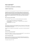
System Unit front view components
The following components are on the front of the All-In-One:
Letter
Component
Function
A
Infrared Light
Produces an invisible (infrared) beam
of light that travels in a straight line,
like the beam of a flashlight. This
beam controls infrared devices, like a
television, cable box, or VCR.
B
Infrared Receiver
This electronic eye “learns” other
infrared remote controls.
C
Off-Hook Indicator
An amber light that illuminates behind
the infrared receiver when the
telephone is off hook
D
Main Speaker
The ECU audibly responds to spoken
commands through this speaker.
continued on next page
1-6
Simplicity™ Family
Copyright © 2001 QTI
System Unit Components, continued
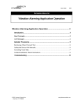
System Unit rear view
Below is a diagram of the rear of the Simplicity™:
continued on next page
Introduction
Copyright © 2001 QTI
1-7
System Unit Components, continued
System Unit rear view components
The following components are on the rear of the Simplicity™:
Letter
Component
Function
A
Reset Button (Red)
Allows the owner to reset and retrain
the unit.
B
Microphone Jack
Where the microphone attaches to the
ECU
C
Remote Microphone
Jack
Where the wireless remote package
plugs into the ECU
D
Dip Switches
Configures the House Code, pulse or
rotary telephone dialing, switch
operation, etc.
E
Accessory Connector 1
and 2
Attaches optional devices, such as
page-turners or door openers. The top
two terminals are Accessory
Connector 1, and the bottom two
terminals are Accessory Connector 2.
F
Modular Phone Jack
Where the phone line plugs into the
ECU
G
Power Jack
Where the power supply plugs into the
ECU
H
Battery Switch
Activates and deactivates the battery
backup
I
Ventilation Holes
Ventilates the ECU.
DO NOT block these openings.
J
External Speaker Jack
Where optional pillow or remote
speakers plug into the ECU
K
External Infrared Jack
Optional cable that repositions infrared
line-of-sight around objects
L
Volume Knob
Adjusts the ECU output volume
M
Bed Connector
Connects the optional bed cable to the
ECU
N
RS232 Serial Port
QTI Use Only
O
Attendant Switch
Used to advance and select menus and
select menu commands
continued on next page
1-8
Simplicity™ Family
Copyright © 2001 QTI
System Unit Components, continued
System Unit rear view components, continued
Introduction
Copyright © 2001 QTI
Letter
Component
Function
P
Audio Output Connector
Connects optional computers,
intercoms, or other devices requiring
audio line level input
Q
Switch Input
Where any Single or Dual ability
switch (such as the Quartet QSP)
connects to the ECU. The Simplicity™
comes with a stereo plug inserted in
the Switch Input. This plug can be
used to solder connections to any
Single or Dual switch to if needed.
1-9
Safety Symbols
Safety Symbols
The following symbols are on the ECU and/or Power Supply Unit:
Symbol
Definition
Caution, refer to documentation
Caution risk of electrical shock
This unit complies with requirements of a Class I device under the
Medical Device Directive of 93/42/EEC.
Class II equipment; the ECU is not earthed.
Type B applied part
This ECU complies with the requirements of UL2601-1, 2nd Edition
(1997) “Medical Electrical Equipment, Part 1: General Requirements
for Safety 2nd Edition Including Amendments 1 and 2”.
This ECU complies with the requirements of CAN/CSA C22.2 No.
601.1-M90, “Medical Electrical Equipment – Part 1: General
Requirements for Safety, including C22.2 No. 601.1S1-94 (IEC6011, Amendment 1:1991) Supplement No. 1-94 to CAN/CSA 22.2 No.
601.1-M90”
1-10
Simplicity™ Family
Copyright © 2001 QTI
Regulatory Approvals
Safety approvals
This ECU complies with the requirements of UL2601-1, 2nd Edition (1997) “Medical
Electrical Equipment, Part 1: General Requirements for Safety 2nd Edition Including
Amendments 1 and 2”.
This ECU complies with the requirements of CAN/CSA C22.2 No. 601.1-M90,
“Medical Electrical Equipment – Part 1: General Requirements for Safety, including
C22.2 No. 601.1S1-94 (IEC601-1, Amendment 1:1991) Supplement No. 1-94 to
CAN/CSA 22.2 No. 601.1-M90”
This ECU complies with the requirements of EN60601-1:1990, including
Amendments A13:1996.
Emissions approval
This ECU complies with the requirements of EMC Directive, number 89/336/EEC,
including EN60601-1-2:1993 and EN50065-1.
Telephone approval
This ECU complies with the conditions specified in NTR-3 Issue 2 Annex A.1.2.
In addition, this ECU complies with the requirements of EN60950:1992,
Amendment 1 & 2:1993 & Amendment 3:1995, (clause 6; connection to
telecommunication networks).
BABT approval
This ECU is approved for connection to telecommunications systems specified in the
instructions for use subject to the conditions set out in them.
BABT approval number: 504117
Introduction
Copyright © 2001 QTI
1-11
Specifications
Acceptable Input
Voltage
110-120VAC, 60Hz, Single Phase
Current
500mA
Input Over Current
Protection
Thermal Cutoffs on all legs of primary
Battery Type
Spill proof, maintenance free, sealed lead-acid
Typical Battery Life
Typical Recharge Time
1 to 3 years, depending on number of discharge cycles and
ambient temperature
24 hours from total discharge
Operating Temperature
32°F to 104°F (0 to 40°C)
Storage Temperature
5°F to 113°F (-15°C to 45°C)
Operating and Storage
Relative Humidity
0 to 95%, non-condensing
Operating Elevation
0 to +10,000ft (0 to +3,000m)
Storage Elevation
0 to +50,000ft (0 to +15,000m)
Size (H x W x D)
5.2” x 7.9” x 10.7” (13.20 x 20.06 x 27.17 cm)
Weight
ECU 11.5lb (5.2kg), PSU 5lb (2.2kg)
Notes:
This equipment is not suitable for use in the presence of a flammable anaesthic
mixture with air or with oxygen or nitrous oxide.
This equipment should be protected against ordinary ingress of water.
This equipment is intended for continuous use.
1-12
Simplicity™ Family
Copyright © 2001 QTI
Cleaning and Maintenance
Cleaning
You can clean the outside of the ECU with a slightly damp cloth, when necessary.
Use water only.
Maintenance
The Simplicity™ unit requires no special cleaning or daily maintenance, other than
the recommended two-year battery replacement. Contact your authorized Quartet
distributor for battery replacement and disposal.
You should annually check microphones, switches, and other accessories for safety
and integrity. Contact your authorized Quartet distributor for necessary repairs or
replacements.
Introduction
Copyright © 2001 QTI
1-13
Accessories
Accessories
A complete line of optional accessories complements the Simplicity™, including:
Accessory
QTI P/N
Description
Pillow speaker
8009
Allows for private telephone
conversations
Infrared extender
8066
Cable that repositions infrared lineof-sight around objects
QSP pneumatic sip and
puff switch
9260
Allows you to control the ECU by
switch activation
Lamp module
8013
Allows you to control incandescent
lamps
Appliance module
8039
Allows you to control devices (fans,
computers)
Radio remote package
9231
Allows you to remotely operate the
ECU with voice or switch commands
Radio remote speaker
package
9250
Allows you to hear the ECU remotely
from your wheelchair.
Contact Quartet Technology or your authorized distributor for more information.
1-14
Simplicity™ Family
Copyright © 2001 QTI
Chapter 2: Installation
Overview
Introduction
Your Simplicity ECU is easy to install and setup. To start using your ECU in
minutes, just follow the instructions outlined in this chapter.
Objectives
In this chapter you learn about:
2-2
•
Plugging in the microphone
•
Adjusting the volume
•
Plugging in the ability switch
•
Setting the dipswitches
•
Setting up the lamp module
•
Connecting a lamp
•
Connecting the power supply
•
Turning the battery back-up on
•
Voice training
Simplicity™ Family
Copyright © 2001 QTI
Connecting the Microphone and Switch
Procedure
1. Identify the microphone that came with the ECU and attach it to the
“Microphone” jack as shown.
2. Turn the volume up (clockwise) about halfway.
3. Plug the ability switch (1/4” jack) you have chosen into the “Switch Input” jack
as shown.
Note: Do not plug the unit into an electrical outlet at this point.
continued on next page
Installation
Copyright © 2001 QTI
2-3
Setting the Dipswitches
Procedure
1. Set the dipswitches located on the back of the unit.
Note: The figure above illustrates a unit that is set for House Code A, tone dialing,
and voice/switch operation.
continued on the next page
2-4
Simplicity™ Family
Copyright © 2001 QTI
Setting up the Lamp Module
Procedure
Using a small Flathead screwdriver, set the Unit number on the Lamp Module to 1
and the House Code to A.
continued on next page
Installation
Copyright © 2001 QTI
2-5
Connecting a Lamp
Procedure
Connect a lamp to the lamp module as follows:
1. Plug a lamp into an electrical outlet and turn it on; verify that the light is on
2. Unplug the lamp from the electrical outlet
3. Plug the lamp into the lamp module
Note: Do not force the line cord into the module.
continued on next page
2-6
Simplicity™ Family
Copyright © 2001 QTI
Connecting a Lamp, continued
4. Plug the lamp module into an electrical outlet.
Note: The lamp must stay switched ON. Other family members can control any lamp
or appliance module using the optional push-button mini controller (QTI P/N
8084).
Note: Do not use any type of surge suppression between the module and the
electrical outlet. This will cause the module to behave erratically.
Note: Lamp modules can only be used with incandescent lamps.
continued on next page
Installation
Copyright © 2001 QTI
2-7
Connecting the Power Supply
Plug the Power Supply into the ECU.
Note: Be sure to plug the connector firmly into place.
continued on the next page
2-8
Simplicity™ Family
Copyright © 2001 QTI
Connecting the Power Supply, continued
Plug the power supply cord into an electrical outlet.
Note: After performing self-diagnostics, the ECU will ask you to say the word
"Testing." Do not say anything; proceed to the next section, Voice Training,
before responding.
Note: If the ECU responds with something other than “Say Testing”, refer to
Appendix A, “ECU Messages”.
continued on next page
Installation
Copyright © 2001 QTI
2-9
Turning the Battery Back-up On
Turn the On/Off switch On to activate the battery charger inside the ECU.
Note: This switch should always be set to the On position except when the ECU will
be off for an extended period of time. The battery backup will not work if the
switch is in the off position and if there is a power failure.
continued on next page
2-10
Simplicity™ Family
Copyright © 2001 QTI
Voice Training
Introduction
When using the voice mode, the ECU operates on a sequence of voice commands.
You must train the unit to recognize your voice before it can respond to your
commands. Before you begin to train your unit, it is important to keep the following
points in mind when speaking into the microphone:
•
Your voice volume and word pronunciation should always be the same.
•
Speak in a clear flat voice. Try to leave any emotion out of your voice. For
example, when asked to say "Yes" don't say "Yes?" as if you were asking a
question. Be firm and say, "Yes."
•
When the ECU asks you to say a word, take your time. Repeat the word to
yourself before speaking into the microphone. Stop for a brief pause after each
word, the ECU will wait.
•
If you make a mistake, don't worry. Stop, collect yourself and continue. Later we
will show you how to correct a misspoken word.
•
You must speak directly into the front of the microphone. Your mouth should be
no more than 1-inch away from the microphone.
The ECU will expect you to say these words the same way every time, so repeat
them the way you normally would. Take your time and don't rush.
continued on next page
Installation
Copyright © 2001 QTI
2-11
Voice Training, continued
Procedure
You are now ready to begin voice training your ECU.
1. Press the red button located on the rear of the unit.
2. The ECU should respond with either "single" or "dual" switch. If the unit does
not, check to make sure you have plugged the ability switch all the way in.
Note: If you have purchased the optional radio remote package,
it should not be connected to the ECU at this time.
3. The ECU will then ask you to say the word "Testing". Pause, and then say
"Testing" into the microphone. It will repeat this command until it adjusts to the
volume of your voice. Do not change the volume of your voice. Pick a
comfortable volume and stay with it. Take your time!!
Note: The first "say Testing" may have to be spoken loudly in order to
"wake-up" the unit. After this, always speak to the unit at the same firm
level.
Pause here for a moment.......
continued on next page
2-12
Simplicity™ Family
Copyright © 2001 QTI
Voice Training, continued
“The Name”
The ECU will ask you to say "the name". The ECU is asking for the name of your
Simplicity ECU. You can name your Simplicity ECU whatever you wish. It is best,
however, if the name you choose does not sound like a word used in conversation.
Try an uncommon name like Egbert, Calvin, or Victor. Stay away from long and
complicated names (i.e., Montezuma) because they may get tiring after awhile. Hard
guttural words work best.
During training when the ECU asks you to say a word, you will repeat that word into
the microphone except when the ECU asks you to say "the Name". At this point, you
say Egbert, Calvin, Victor, or whatever name you have chosen.
Training
The ECU will now ask you to say a series of words.
Note: Appendix B contains a complete listing
After you have completed repeating all the words, you will hear the sound of three
clicks. This confirms that you have successfully trained your ECU to recognize the
words you repeated. You can now turn on your lamp through the use of voice
commands.
continued on next page
Installation
Copyright © 2001 QTI
2-13
Turning on a lamp by voice or switch
Introduction
Most commands use the three steps below to perform a function.
Voice Mode
1. Call the units name. (Egbert, Calvin, etc..)
2. Choose a menu function. (Light, Telephone, Bed, etc..)
3. Give a command. (Allon, Shutoff, Up, etc..)
Switch Mode
1. Activate the unit using the ability switch you have chosen.
2. Choose a menu function. (Light, Telephone, Bed, etc..)
3. Choose a command. (Allon, Shutoff, Up, etc..)
Activate a lamp
You can turn on all your lamp modules by activating the unit, choosing a menu
(Light), followed by a command (Allon).
Now it is your turn to try. To turn on your lamp do the following:
Voice Mode
Say: "Egbert", "Light", "Allon"
Switch Mode
Activate the unit, select "Light", and select "Allon"
Congratulations! You have just entered the world of environmental control!
2-14
Simplicity™ Family
Copyright © 2001 QTI
Chapter 3: Controlling your environment
Overview
Voice Commands
You train the Simplicity™ to respond to a sequence of spoken words. These voice
commands are made up of the same words you trained in Chapter 2. The examples in
this chapter refer to the Simplicity™ as "Egbert". To activate "Egbert", you must first
say its name. "Egbert" can now respond to any command sequence.
Voice Example
To turn on a light, first say: "Egbert". "Egbert" responds by saying, "Yes?”
Then say: "Light". "Egbert" responds by saying "Light".
Say "Allon". "Egbert" responds by saying "Allon". The ECU will repeat the word it
understood you to say. You can turn this "echo" feature off later if you wish.
Until you memorize the sequences of commands and have learned to pronounce your
words the same way, remember:
•
If you forget a command or if "Egbert" keeps saying, "Excuse me", just say
"Help-me". "Egbert" responds with a list of commands you can choose from.
•
At any time you can say, "Cancel" to stop the whole process. Say the name
("Egbert") to activate the unit again.
•
You must always pronounce words exactly the same way. For example, if you
train "Egbert" to recognize "Turnon" in a flat voice and you say "Turnon?" with
a rise at the end, "Egbert" responds with "Excuse me?” It cannot recognize
different pronunciations of the same word.
Note: If "Egbert" keeps saying, "Excuse me?" and does not respond to a different
pronunciation of the word, say "Helpme". You may be using the wrong
command.
continued on next page
3-2
Simplicity™ Family
Copyright © 2001 QTI
Overview, continued
Switch Commands
The ECU operates upon activation from an ability switch you have chosen attached
to the unit.
If you are using a "dual" switch, one side of the switch will activate the unit and
cause it to begin scanning through the menus (called the "Advance" side). The other
side of the switch (when activated) will select the current menu choice (called the
"Select" side).
If you are using a "single" switch, activating the switch once will cause the unit to
start scanning the menus. Activating the switch again, will select the current menu
choice.
The speed at which the unit verbally outputs the menu choices is configurable. (See
Owner’s Manual, Chapter 3) When using a "dual" switch, the menu speed delay can
be overridden by continuously activating the "Advance" side.
As with the menu speed, the "switch" speed (sometimes called the switch acceptance
rate) is also configurable. (See Owner’s Manual, Chapter 3)
Another unique feature of the Simplicity™ is the ability to "customize" entire menu
groups or selected commands within a menu group. (See Owner’s Manual, Chapter
3)
After activating your Simplicity with your ability switch, you have your choice of the
following menus:
•
•
•
•
•
•
•
Phone
Light
Appliance
Television
Cable
VCR
Remote 1
Controlling your environment
Copyright © 2001 QTI
•
•
•
•
•
•
Remote 2
Remote 3
Bed
Accessory
Utility
Cancel
3-3
Overview, continued
Switch Example
To turn on a light, activate the ability switch.
The ECU will start verbally scanning by saying, "Phone", “Light”, ….
When the ECU says “Light”, activate the ability switch again.
The ECU will start verbally scanning the “Light” menu by saying, "Turnon",
“Shutoff”, ….
When the ECU says “Allon”, activate the ability switch again.
3-4
Simplicity™ Family
Copyright © 2000 QTI
Chapter 4: Configuring the House Code
Overview
Introduction
The Simplicity™ can control up to 32 compatible X-10™ modules. Using the Light (or
Appliance) menu you can:
•
Turn on all lamp modules simultaneously
•
Shut off all modules simultaneously
•
Turn on or shut off a particular module(s)
•
Brighten or dim any lamp module(s)
•
Activate a remote chime module
•
Control a thermostat module
•
Control a wall switch module
Objectives
In this chapter you will learn about:
•
4-2
Configuring House Code setting
Simplicity™ Family
Copyright © 2001 QTI
Configuring the House Code
House Code
Control modules use a House Code and a Unit Code. Select the same House Code for
every module in your house. Select a unique Unit Code for each module.
Your Simplicity™ is factory set to House Code "A" for the "Light" menu, and "B" for
the appliance menu. You should not have to change this setting unless someone
nearby also uses X-10 devices.
To change the House Code, locate the dipswitches on the back of the unit.
Use the information in the following table to configure dipswitches 1 through 4.
continued on next page
Configuring House Codes
Copyright © 2001 QTI
4-3
Configuring the House Code, continued
House Code Table
Light
Menu
House
Code
Appliance
Menu
House
Code
Dipswitch 1
Dipswitch 2
Dipswitch 3
Dipswitch 4
A
B
On
On
On
On
B
C
On
On
On
Off
C
D
On
On
Off
On
D
E
On
On
Off
Off
E
F
On
Off
On
On
F
G
On
Off
On
Off
G
H
On
Off
Off
On
H
I
On
Off
Off
Off
I
J
Off
On
On
On
J
K
Off
On
On
Off
K
L
Off
On
Off
On
L
M
Off
On
Off
Off
M
N
Off
Off
On
On
N
O
Off
Off
On
Off
O
P
Off
Off
Off
On
P
P
Off
Off
Off
Off
*Note: The appliance House Code is automatically assigned. For example, if you
configure dip switches 1 through 4 to Off, On, Off, On, respectively, then the
House Code for the "Light" menu will be "K" and the House Code for the
"Appliance" menu will automatically be set to "L".
X-10 Groups
The Simplicity™ uses two menus for controlling X-10™ modules: Light and
Appliance. Both these menus are functionally identical. Each menu is capable of
controlling up to sixteen modules. There are a wide variety of modules available to
control many items. Any module can be used in either menu group.
In addition, there are another two sub-menus in the Accessory menu that are capable
of controlling up to sixteen modules each. This brings the total number of X-10™
modules that can be controlled to 64. Refer to Chapter 10, “Accessory Control” for
details on configuring these additional groups.
4-4
Simplicity™ Family
Copyright © 2001 QTI
Chapter 5: Connecting the Telephone
Overview
Introduction
The Simplicity™ contains a full featured, integrated, high quality telephone with
ringer. The phone menu is one of the most powerful tools within the unit.
Whether by switch, voice, or the optional remote package, you can communicate on
the telephone from anywhere in your environment as well as perform all other ECU
functions.
Some of the many telephone features are:
•
•
•
•
•
•
•
•
•
•
•
•
•
•
•
•
•
•
•
Answer or hang-up the phone
Answer a "call waiting"
Dial a random telephone number
Redial the last telephone number automatically
Put a caller on "hold"
Choose to have a "private" conversation
Store up to 100 telephone numbers
"Speed dial" up to 100 telephone numbers
Enter up to 35 digits per speed dial location
Nonvolatile memory storage
Change the telephone listening volume
Review any stored telephone number
Quick Dial™ - Navigate voice mail systems (voice only)
Turn the telephone ringer on or off
Perform other ECU functions while on the telephone
Automatically places callers on hold when accessing other ECU functions
Phone is fully functional during power outages
Built in surge protection
X-10™ Off-Hook Indicator
Objectives
In this chapter you will learn about:
•
5-2
Connecting the ECU to the telephone line
Simplicity™ Family
Copyright © 2001 QTI
Connecting the Telephone Line
Introduction
Once you connect your Simplicity™ unit to a telephone line, you can use switch or
voice commands to access any of the above-mentioned features.
Procedure
1. Connect one end of the six-foot telephone cable (supplied) to the phone jack on
the back of the Simplicity™ unit.
2. Disconnect the current telephone (if there is one) from the wall.
3. Install telephone "splitter" into wall jack.
4. Connect both the Simplicity and (optionally) your existing phone into the
"splitter" as shown.
Note: The Simplicity does not need to have an external telephone for operation.
5. Be sure both ends of the telephone cable "snap" and lock into place.
6. Locate dipswitch number 5 on the back of the Simplicity. Slide the switch to
"Off" if you have rotary dial service, "On" (factory setting) if you have tone dial
service. Pulse dialing is not selectable in countries that do not support pulse
dialing.
Connecting the Telephone
Copyright © 2001 QTI
5-3
X-10 Off-Hook Indicator
Definition
The X-10 off-hook indicator option allows you to:
•
•
Turn on an X-10 module automatically when the phone is answered
Shut off an X-10 module automatically when the phone is hung-up
Note
The module used for this feature must be set to P-16. Refer to Chapter 2,
“Installation”, “Setting up the Lamp Module”, for details on how to set the house
and unit code for the module.
Procedure
To configure your ECU to enable the X-10 off-hook option, select [say] the
following:
Enable X-10 Option
[Egbert]-Utility-Two-Four
You are now prompted with:
"Deleted”
Select [say] "Turnon".
The X-10 off-hook option is now enabled.
Disable X-10 Option
[Egbert]-Utility-Two-Four
You are now prompted with:
"Enabled”
Select [say] "Shutoff".
The X-10 off-hook option is now deleted.
5-4
Simplicity™ Family
Copyright © 2001 QTI
Chapter 6: Television Codes
Overview
Introduction
The Simplicity can be configured to control most televisions. Using the television
menu you can:
•
Turn on or off the television
•
Change the volume
•
Change the channels
•
Mute the volume
•
Toggle between two channels
•
Operate specially configured keys
Objectives
In this chapter you will learn about:
•
6-2
Entering a 3 digit brand code
Simplicity™ Family
Copyright © 2001 QTI
Configuring the Television Menu
Brand Codes
Before operating your television with switch or voice commands, you must first
configure your ECU to recognize your television. To operate a television, which uses
a remote control, first find your TV brand code listed in Appendix C.
Many of the brands listed have multiple codes. When more than one code is
available, enter the codes in the order listed until the television responds correctly.
If none of the codes listed works, the ECU will have to "learn" the remote control
that came with the television. Refer to Chapter 14, "Learning Infrared".
Note
The Simplicity can only operate televisions which already use a remote control. It
cannot operate a television that is not remote control ready.
Procedure
To train your ECU to recognize your TV brand code, select [say] the following:
[Egbert]-Utility-Television
Note: Three digit television brand codes can only be used in the "Television" or
"Remote 1” menu groups.
You are now prompted with the question:
"Do you want to enter a three digit number?”
Select [say] "Yes". You are now prompted with:
"Say the first digit."
Select [say] the first digit of your TV code. After you select [say] the first digit, the
ECU will repeat it to verify it heard it correctly and ask you to:
“Say the second digit."
Select [say] the second digit of your TV code.
continued on next page
Television Codes
Copyright © 2001 QTI
6-3
Configuring the Television Menu, continued
After you select [say] the second digit, the ECU will repeat it to verify it heard it
correctly and ask you to:
"Say the third digit."
Select [say] the third digit of your TV code. After you select [say] the third digit, the
ECU will repeat it to verify it heard it correctly. After a short delay (approximately
30 seconds), the unit will respond with:
"Training Complete."
You will hear three clicks signifying you have successfully trained the unit to
recognize your TV brand code. You are now ready to proceed to controlling your TV
using switch or voice commands.
Note
Before you can operate your television, make sure the front of the Simplicity is
facing your television and is within 15 to 20 feet of it. Make sure nothing is blocking
the ECU's view of your television.
6-4
Simplicity™ Family
Copyright © 2001 QTI
Chapter 7: Cable Codes
Overview
Introduction
The Simplicity can be configured to control most cable boxes. Using the cable menu
you can:
•
Turn on or off the cable box
•
Change the volume
•
Change the channels
•
Mute the volume
•
Toggle between two video inputs
•
Operate specially configured keys
Objectives
In this chapter you will learn about:
•
7-2
Entering a 3 digit brand code
Simplicity™ Family
Copyright © 2001 QTI
Configuring the Cable Menu
Brand Codes
Before operating your cable box with switch or voice commands, you must first
configure your ECU to recognize your cable box. To operate a cable box, which uses
a remote control, first find your cable box brand code listed in Appendix D.
Many of the brands listed have multiple codes. When more than one code is
available, enter the codes in the order listed until the cable box responds correctly.
If none of the codes listed works, the ECU will have to "learn" the remote control
that came with the cable box. Refer to Chapter 14, "Learning Infrared".
Note
The Simplicity can only operate cable boxes which already use a remote control. It
cannot operate a cable box that is not remote control ready.
Procedure
To train your ECU to recognize your cable box brand code, select [say] the
following:
[Egbert]-Utility-Cable
Note: Three digit cable box brand codes can only be used in the "Cable" or
"Remote 2” menu groups.
You are now prompted with the question:
"Do you want to enter a three digit number?”
Select [say] "Yes". You are now prompted with:
"Say the first digit."
Select [say] the first digit of your cable box code. After you select [say] the first
digit, the ECU will repeat it to verify it heard it correctly and ask you to:
“Say the second digit."
Select [say] the second digit of your cable box code.
continued on next page
Cable Codes
Copyright © 2001 QTI
7-3
Configuring the Cable Menu, continued
After you select [say] the second digit, the ECU will repeat it to verify it heard it
correctly and ask you to:
"Say the third digit."
Select [say] the third digit of your cable box code. After you select [say] the third
digit, the ECU will repeat it to verify it heard it correctly. After a short delay
(approximately 30 seconds), the unit will respond with:
"Training Complete."
You will hear three clicks signifying you have successfully trained the unit to
recognize your cable box brand code. You are now ready to proceed to controlling
your cable box using switch or voice commands.
Note
Before you can operate your cable box, make sure the front of the Simplicity is
facing your cable box and is within 15 to 20 feet of it. Make sure nothing is blocking
the ECU's view of your cable box.
7-4
Simplicity™ Family
Copyright © 2001 QTI
Chapter 8: VCR Codes
Overview
Introduction
The Simplicity can be configured to control most VCR’s. Using the VCR menu you
can:
•
Turn on or off the VCR
•
Play a video tape
•
Record a video tape
•
Rewind a tape
•
Fast forward a tape
•
Pause a tape
•
Stop a tape
•
Change the volume
•
Change the channels
•
Toggle between TV and VCR modes
•
Operate specially programmed keys
Objectives
In this chapter you will learn about:
•
8-2
Entering a 3 digit brand code
Simplicity™ Family
Copyright © 2001 QTI
Configuring the VCR Menu
Brand Codes
Before operating your VCR with switch or voice commands, you must first configure
your ECU to recognize your VCR. To operate a VCR, which uses a remote control,
first find your VCR brand code listed in Appendix E.
Many of the brands listed have multiple codes. When more than one code is
available, enter the codes in the order listed until the VCR responds correctly.
If none of the codes listed works, the ECU will have to "learn" the remote control
that came with the VCR. Refer to Chapter 14, "Learning Infrared".
Note
The Simplicity can only operate VCR’s which already use a remote control. It cannot
operate a VCR that is not remote control ready.
Procedure
To train your ECU to recognize your VCR brand code, select [say] the following:
[Egbert]-Utility-VCR
Note: Three digit VCR brand codes can only be used in the "VCR" or
"Remote 3” menu groups.
You are now prompted with the question:
"Do you want to enter a three digit number?”
Select [say] "Yes". You are now prompted with:
"Say the first digit."
Select [say] the first digit of your VCR code. After you select [say] the first digit, the
ECU will repeat it to verify it heard it correctly and ask you to:
“Say the second digit."
Select [say] the second digit of your VCR code.
continued on next page
VCR
Copyright © 2001 QTI
8-3
Configuring the VCR Menu, continued
After you select [say] the second digit, the ECU will repeat it to verify it heard it
correctly and ask you to:
"Say the third digit."
Select [say] the third digit of your VCR code. After you select [say] the third digit,
the ECU will repeat it to verify it heard it correctly. After a short delay
(approximately 30 seconds), the unit will respond with:
"Training Complete."
You will hear three clicks signifying you have successfully trained the unit to
recognize your VCR brand code. You are now ready to proceed to controlling your
VCR using switch or voice commands.
Note
Before you can operate your VCR, make sure the front of the Simplicity is facing
your VCR and is within 15 to 20 feet of it. Make sure nothing is blocking the ECU's
view of your VCR.
8-4
Simplicity™ Family
Copyright © 2001 QTI
Chapter 9: Bed Cable Installation
Overview
Introduction
The Simplicity contains a built-in electric bed controller. Using the bed menu you
can:
•
Raise or lower the bed
•
Raise or lower the foot
•
Raise or lower the head
Once the bed cable is connected, you can use voice or switch commands to access
any of the above-mentioned features.
Objectives
In this chapter you will learn about:
•
•
9-2
Installing the optional bed cable
Configuring the consecutive access option (switch only)
Simplicity™ Family
Copyright © 2001 QTI
Installing the Bed Cable
Procedure
The optional bed cable consists of a 20-foot cable with a "Y" connection on one end.
To connect your bed cable:
•
Connect one end of the bed cable to the Bed Connector on the back of the
Simplicity unit shown as “A” below.
•
Unplug the existing hand pendent controller from the bed.
•
Plug one side of the "Y" on the bed cable into the bed.
•
Plug the existing hand pendent into the other side of the "Y" on the bed cable.
Note
The Simplicity can only operate low voltage beds whose hand pendants support the
above features. It cannot control the bed if the bed manufacturer does not offer the
function.
Caution
Only low voltage, low current devices should be connected to the switch terminals.
Do not switch AC line voltages. The maximum rating for the accessory port
switches is 30 VDC, or 30 VAC at a maximum current of .5 Amps.
Caution
All cabling should be properly secured to prevent damage to the cables and/or ECU.
Bed Cable Installation
Copyright © 2001 QTI
9-3
Consecutive Access Option
Definition
The consecutive access option allows you to:
•
Change the number of times (from one to four) you can adjust the movement of
the bed, up or down, using a switch. The factory default is two.
Note
The consecutive access option is intended to prevent a switch user from raising or
lowering the head, foot, or mattress of the bed more then a pre-determined number of
times in any one direction.
This feature prevents unintended operation of the of the bed in the event of a switch
failure.
Note
The length of time the bed moves cannot be changed.
Procedure
To configure your ECU to change the number of consecutive accesses, select [say]
the following:
[Egbert]-Utility-Keyboard-Two-Eight
You are now prompted with:
"Two” (factory default)
Select [say] a number from “1” to “4”
9-4
Simplicity™ Family
Copyright © 2001 QTI
Chapter 10: Accessory Control
Overview
Introduction
The Simplicity provides control of standard accessories such as door openers, pageturners, drapery controls, nurse calls, etc. When selected by switch or verbal
command, the chosen Accessory port, 1 or 2, will momentarily be closed.
The Accessory menu also contains two optional X-10 menus that can be enabled to
provide additional control for 32 modules.
Objective
In this chapter you will learn about:
10-2
•
Location of Accessory ports 1 and 2
•
Attaching an accessory to the ECU
•
Configuring the “on time” for each accessory port
•
Configuring “loop” option
•
Configuring addition X-10 menus
Simplicity™ Family
Copyright © 2001 QTI
Configuring the Accessory Ports
Port Identification
The illustration below identifies the Accessory connector. Note that the top two
terminals belong to "Accessory 1" and the bottom two terminals belong to
"Accessory 2". These two terminals function just like a doorbell button. When
selected, the terminals are momentarily connected to each other.
Warning
ONLY LOW VOLTAGE, LOW CURRENT DEVICES SHOULD BE
CONNECTED TO THE SWITCH TERMINALS. DO NOT ATTEMPT TO
SWITCH AC LINE VOLTAGES!
Note
The maximum rating for the accessory ports switches is 30 VDC or 30 VAC at a
maximum current of .5 Amps.
continued on next page
Accessory Control
Copyright © 2001 QTI
10-3
Configuring the Accessory Ports, continued
Note
Most accessories use 5 to 12 volts to make them operate. These can be easily
handled by the Simplicity. However, the Simplicity is not designed for high current
or high voltage AC. You cannot, for example, use the Accessory connector to switch
a light on and off.
If you have any doubts about hooking up an accessory, contact the manufacturer of
the accessory you wish to control, or have a qualified, licensed electrician perform
the installation.
Attaching an Accessory
To connect an accessory to one of the accessory ports, unplug the green accessory
connector from the back of the ECU.
Using a small Flathead screwdriver, unscrew the setscrews in the accessory
connector (either 1 or 2) counter-clockwise.
Take one of the two wires used to control the accessory device and insert it into one
side of the accessory connector. Take the other wire and insert it into the other side
of the accessory connector.
Using a small Flathead screwdriver, screw the setscrews into the accessory connector
(either 1 or 2) clockwise. Do not over tighten!
Remember, that the top two terminals belong to "Accessory 1" and the bottom two
terminals belong to "Accessory 2".
10-4
Simplicity™ Family
Copyright © 2001 QTI
Configuring the Accessory Ports, continued
On Times
The "on time" (closed time) for Accessory 1 and 2 can be individually set. This time
can be adjusted from approximately .5 seconds to 8 seconds, in .5 second increments.
Configuring Accessory 1 "On Time"
To configure the "on time" for accessory one, select [say] the following:
[Egbert]-Utility-Keyboard-One-Eight
Note: After selecting [saying] "Keyboard", the unit will respond with "Say cancel".
If you wish to exit, select [say] "Cancel". Otherwise, ignore this message and
continue.
The ECU will verbally respond with the current setting:
"(Number)" (The factory default is 1 second.)
Choose a number from 1 (minimum) to 16 (maximum). The new hold time is now
entered. Remember that each number represents approximately .5 seconds. Thus,
entering 5 would cause Accessory 1 to close for approximately 2.5 seconds when
activated.
Example
Task
Change Accessory 1
“On Time” from 1
second (default) to 16
seconds
Say:
Egbert
Utility
Keyboard
One
Eight
ECU Response
One
Sixteen
continued on next page
Accessory Control
Copyright © 2001 QTI
10-5
Configuring the Accessory Ports, continued
Configuring Accessory 2 "On Time"
To configure the "on time" for accessory two, select [say] the following:
[Egbert]-Utility-Keyboard-One-Nine
Note: After selecting [saying] "Keyboard", the unit will respond with "Say cancel".
If you wish to exit, select [say] "Cancel". Otherwise, ignore this message and
continue.
The ECU will verbally respond with the current setting:
"(Number)" (The factory setting is 1 seconds.)
Choose a number from 1 (minimum) to 16 (maximum). The new hold time is now
entered. Remember that each number represents approximately .5 seconds. Thus,
entering 5 would cause Accessory 2 to close for approximately 2.5 seconds when
activated.
Example
Task
Change Accessory 2
“On Time” from 1
second (default) to 16
seconds
Say:
Egbert
Utility
Keyboard
One
Nine
ECU Response
One
Sixteen
Looping
Both Accessory ports 1 and 2 can be configured to loop or not. When looping is
configured for an accessory port, you can activate the Accessory port contact again
and again by selecting [saying] “x”, where “x” is the accessory number.
If looping is enabled, you must specify Cancel to exit the menu.
The factory default for Accessory 1 is looping deleted. The factory default for
Accessory 2 is looping enabled.
10-6
Simplicity™ Family
Copyright © 2001 QTI
Configuring Additional X-10 Menus
Definition
There are two sub-menus in the Accessory menu that are capable of controlling up to
sixteen modules each. These sub-menus are called “Light” and “Appliance”. This
brings the total number of X-10™ modules that can be controlled by the ECU to 64.
Objective
In this section you will learn about:
•
Enabling and deleting the additional “Light” menu.
•
Enabling and deleting the additional “Appliance” menu
•
Configuring house codes for these two menus
Procedure
To configure your ECU to enable the additional X-10 menus, select [say] the
following:
Enable Additional Light Menu
[Egbert]-Utility-Keyboard-Three-Five
You are now prompted with:
"Deleted”
Select [say] "Turnon".
The additional Light menu is now enabled.
Delete Additional Light Menu
[Egbert]-Utility-Keyboard-Three-Five
You are now prompted with:
"Enabled”
Select [say] "Shutoff".
The additional Light menu is now deleted.
Accessory Control
Copyright © 2001 QTI
10-7
Configuring Additional X-10 Menus (cont.)
Enable Additional Appliance Menu
[Egbert]-Utility-Keyboard-Three-Seven
You are now prompted with:
"Deleted”
Select [say] "Turnon".
The additional Appliance menu is now enabled.
Delete Additional Appliance Menu
[Egbert]-Utility-Keyboard-Three-Seven
You are now prompted with:
"Enabled”
Select [say] "Shutoff".
The additional Appliance menu is now deleted.
10-8
Simplicity™ Family
Copyright © 2001 QTI
Configuring the House Codes
Definition
There are two sub-menus (Light and Appliance) in the Accessory menu can be
configured for House Codes A thru P. The factory default is C and D respectively.
Objective
In this section you will learn how to:
•
Change the House Code for the “Light” menu.
•
Change the House Code for the “Appliance” menu.
Configuring the Light Menu
To configure the Light menu house code, select [say] the following:
[Egbert]-Utility-Keyboard-Three-Six
You are now prompted with:
"Three” (factory default, corresponds to House Code C )
Select [say] "X", where “x” is a number corresponding to a house code as shown in
the following table.
Configuring the Appliance Menu
To configure the Appliance menu house code, select [say] the following:
[Egbert]-Utility-Keyboard-Three-Six
You are now prompted with:
"Four” (factory default, corresponds to House Code D)
Select [say] "X", where “x” is a number corresponding to a house code as shown in
the following table.
Accessory Control
Copyright © 2001 QTI
10-9
Configuring the House Codes (cont.)
House Code Table
House
Code
Number
A
1
B
2
C
3
D
4
E
5
F
6
G
7
H
8
I
9
J
10
K
11
L
12
M
13
N
14
O
15
P
16
Note
The above table is for configuring the additional X-10 menu house codes in the
Accessory group only.
The main menus, Light and Appliance, are configured using the dipswitches as
explained in Chapter 4, “Configuring the House Code”, of the Installation Manual.
10-10
Simplicity™ Family
Copyright © 2001 QTI
Chapter 11: Retraining
Overview
Introduction
The Simplicity contains a "Retrain" utility that allows for correction of mistrained
words.
Let's say you're going through the words during the training session. The ECU just
said, "Please say the word Down". You start to repeat "Down" but someone
interrupts you and you say "what?” The ECU will now accept this as your
pronunciation of the word "Down", and move on to the next word. Now you're
stuck—the ECU has a bad word trained.
Or, what if the ECU is already trained, and every time you say a word to the ECU
during command sequences, it keeps saying, "Excuse me?” Maybe during training
you said the word with a particular pronunciation or a different tone of voice than
you usually use. No problem!
As you will see, any word(s) can be retrained at any time.
Objective
In this chapter you will about:
•
11-2
Retraining selected words
Simplicity™ Family
Copyright © 2001 QTI
Retraining Words
Retraining
To start the retraining process, simply say "Egbert," wait for the ECU to respond
"Yes?" and then say "Retrain". The ECU will go through the first six words, one at a
time, and ask if you want that particular word retrained. If the word to be retrained
is not one of the first six words, the ECU will ask you which group the word is in to
be retrained.
The ECU expects a "Yes" or "No" as a response. If you say "No", the ECU will
move on to the next word. If you respond with "Yes", the ECU will start the retrain
sequence for that particular word.
When you are finished retraining a word, simply say Cancel. The new word will be
updated and stored away for future use.
Example
"Egbert" is having trouble recognizing the word "Light". The following sequence
will rectify this situation.
Note: The following procedure assumes the ECU has been named “Egbert”.
Tasks:
Retrain
Say:
ECU Response:
Egbert
Yes
Retrain
Do you want to retrain the word “Cancel”?
No
Do you want to retrain the word “Help-me”?
No
Do you want to retrain “The Name”
No
Retrain “Yes”?
No
Retrain “No”?
No
Do you want to retrain the word “Retrain”?
No
Do you want to retrain a number?
No
Do you want to retrain a word from the menu group
“Lights”?
Yes
Retrain “Light”?
Yes
Say “Light”
Light
Say “Light”
Light
Retrain “Allon”?
Cancel
continued on next page
Retraining
Copyright © 2001 QTI
11-3
Retraining Words, continued
The ECU will ask you to say the word "Lights" two times. Take your time! The
new word(s) will be saved. The ECU will continue on, asking if you wish to train
the next word. Respond with "Cancel" if there are no more words to be retrained.
11-4
Simplicity™ Family
Copyright © 2001 QTI
Chapter 12: Utility Functions
Overview
Introduction
There are several functions included to enhance the use of the Simplicity™ ECU.
You can optionally do things like toggle the power failure announcement on and off,
or reset the optional VMK feature.
Objectives
In this chapter, you learn how to use each Utility Function, including:
12-2
•
Echo Mode
•
Tone Mode
•
Voice/Mouse Keyboard Reset
•
System Status
•
Breakout Mode
•
Telephone Ringer Mode
•
Power Fail Warning
•
Menu Privacy Mode
•
Light Shutoff
•
Nurse Call Light
Simplicity™ Family
Copyright © 2001 QTI
The Utility Functions
Utility Functions
To use any of the Utility functions, you first access the Utility Menu. Then you use
Voice or Switch commands to access each Utility Function by number:
Function
Number
Utility Functions
Copyright © 2001 QTI
Mode
Function
1
Echo Mode
Repeats all recognized words
2
Tone Mode
3
4
Voice/Mouse Keyboard
Reset
System Status Mode
5
Breakout Mode
6
Telephone Ringer Mode
7
Power Fail Warning
8
Menu Privacy Mode
Produces a “soft” tone in the Computer
Menu
Resets the optional VMK feature (if
installed)
Reports system status; used by Quartet
Technology Inc.
In voice Automatically exits the system
after the ECU prompts Excuse Me five
consecutive times
Turns on or shuts off the telephone
ringer
Turns on or shuts off the power fail
announcement
Turns on or shuts off the main speaker
9
Light Shutoff
Sends a P-16 shutoff command
10
Nurse Call Light
Sends a P-15 shutoff command
12-3
Echo Mode
Definition
When enabled, Echo Mode repeats all recognized words. Echo Mode is only
available in voice mode.
Enable Echo Mode
Complete the following to enable the Echo Mode:
Task
Enable Echo Mode
Say:
Select:
Egbert
Utility
Function
One
Utility
Function
One
Turnon
Turnon
ECU Response
Say Deleted
Note: Selecting this utility for the first time prompts the ECU to respond Say
Enable.
Echo Mode is enabled and the ECU will repeat each recognized word.
Delete Echo Mode
You may want to delete the Echo Mode after you feel comfortable using the ECU,
and do not want to have each command you speak repeated back to you. When Echo
Mode is deleted, the ECU only repeats Yes, Excuse Me, and any numbers you speak
while using the Phone, Light, or Appliance Menus.
Complete the following to delete the Echo Mode:
Task
Delete Echo Mode
Say:
Select:
Egbert
Utility
Function
One
Utility
Function
One
Shutoff
Shutoff
ECU Response
Say Enabled
Echo Mode is turned off. You can enable Echo Mode at any time.
12-4
Simplicity™ Family
Copyright © 2001 QTI
Tone Mode
Definition
If you have the optional Voice/Mouse Keyboard (VMK™) product installed, this
mode produces a “soft” tone in the Computer Menu. All recognized words in the
Computer Menu generate a “soft” tone to verify that a word was recognized.
Note
If the Echo Mode is enabled, the Tone Mode is suppressed. To enable the Tone
Mode, you must first delete the Echo Mode. See the prior page for detail on this
process.
Enable Tone Mode
Complete the following to enable the Tone Mode:
Task
Enable Tone Mode
Say:
Select:
Egbert
Utility
Function
Two
Utility
Function
Two
Turnon
Turnon
ECU Response
Deleted
Note: Selecting this mode for the first time prompts the ECU to respond
Enabled.
The Tone Mode is enabled and the ECU generates a “soft” tone for each
recognized Command Word in the Computer Menu.
Delete Tone Mode
Complete the following to delete the Tone Mode:
Task
Say:
Select:
Delete Tone Mode
Egbert
Utility
Function
Two
Utility
Function
Two
Shutoff
Shutoff
ECU Response
Enabled
The Tone Mode utility is turned off. You can enable the Tone Mode utility at any time.
continued on next page
Utility Functions
Copyright © 2001 QTI
12-5
Tone Mode, continued
The Tone Mode is turned off. You can enable the Tone Mode at any time.
Note
To run the ECU silently while in the VMK menus:
12-6
•
Delete Echo Mode
•
Delete Tone Mode
Simplicity™ Family
Copyright © 2001 QTI
Voice/Mouse Keyboard Reset
Definition
The optional VMK feature (QTI P/N: 9230) provides a complete voice interface
allowing full control of both keyboard and mouse functions of any IBM-compatible
personal computer. If you have this feature installed, you can reset it with the VMK
reset utility.
Note
A VMK reset may be necessary if your desktop keyboard and VMK are not working
together properly. Resetting the VMK feature does not reset the ECU.
Reset VMK
Complete the following to reset the VMK:
Task
Reset VMK
Say:
Egbert
Utility
Function
Three
Select:
Utility
Function
Three
ECU Response
Mouse, Keyboard, Up
If the reset was not successful, the ECU responds with a status message. Refer
to Appendix A, ECU Messages, for detailed explanation of each status message
the ECU may issue.
Utility Functions
Copyright © 2001 QTI
12-7
System Status
Definition
The System Status mode is used by Quartet Technology or your authorized
distributor to evaluate the ECU’s status.
Check System Status
Complete the following to check the system status:
Task
Check System status
12-8
Say:
Egbert
Utility
Function
Four
Select:
Utility
Function
Four
ECU Response
(ECU responds with a
list of status codes)
Simplicity™ Family
Copyright © 2001 QTI
Breakout Mode
Definition
When enabled, the Breakout Mode automatically exits the system after the ECU
prompts, “Excuse Me?” five consecutive times.
By default, the Breakout Mode is enabled.
Delete Breakout Mode
You may want to delete this mode after you are very comfortable using the ECU.
Complete the following to delete the Breakout Mode:
Task
Delete Breakout Mode
Say:
Select:
Egbert
Utility
Function
Five
Utility
Function
Five
Shutoff
Shutoff
ECU Response
Excuse Me Enabled
The Breakout Mode is turned off. You can enable this mode at any time.
Enable Breakout Mode
Complete the following to enable the Breakout Mode:
Task
Enable Breakout Mode
Say:
Select:
Egbert
Utility
Function
Five
Utility
Function
Five
Turnon
Turnon
ECU Response
Excuse Me Deleted
The Breakout Mode is enabled.
Utility Functions
Copyright © 2001 QTI
12-9
Telephone Ringer Mode
Definition
When enabled, the Telephone Ringer Mode turns on the telephone ringer. By
default, Telephone Ringer Mode is deleted.
Enable Telephone Ringer Mode
Complete the following to enable the Telephone Ringer Mode:
Task
Enable Telephone
Ringer Mode
Say:
Select:
Egbert
Utility
Function
Six
Utility
Function
Six
Turnon
Turnon
ECU Response
(Ring) Deleted
The Telephone Ringer Mode is enabled and the telephone ringer is turned on.
Delete Telephone Ringer Mode
You may want to delete this mode if you do not wish to hear the phone ring.
Complete the following to delete the Telephone Ringer Mode:
Task
Enable Telephone
Ringer Mode
Say:
Select:
Egbert
Utility
Function
Six
Utility
Function
Six
Shutoff
Shutoff
ECU Response
(Ring) Enabled
The Telephone Ringer Mode is deleted and the telephone ringer is turned off.
You can enable the Telephone Ringer Mode at any time.
12-10
Simplicity™ Family
Copyright © 2001 QTI
Power Fail Warning
Definition
When enabled, the Power Fail Warning mode turns on or shuts off the power fail
announcement. By default, the Power Fail Warning is enabled.
Note
You may want to delete this mode if the AC power goes off for an extended period
of time and you do not wish to hear the power fail warning repeated every minute.
Delete Power Fail Warning
Complete the following to delete the Power Fail Warning:
Task
Delete Power Fail
Warning Mode
Say:
Select:
Egbert
Utility
Function
Seven
Utility
Function
Seven
Shutoff
Shutoff
ECU Response
Power Failure
Enabled
The Power Fail Warning is turned off, and you will not hear an announcement if
the power fails.
Note: Once the power comes back on, the ECU automatically enables the Power
Fail Warning for you.
Enable Power Fail Warning
Complete the following to enable the Power Fail Warning mode:
Task
Delete Power Fail
Warning Mode
Say:
Select:
Egbert
Utility
Function
Seven
Utility
Function
Seven
Turnon
Turnon
ECU Response
Power Failure
Deleted
The Power Fail Warning is turned on, and you will hear an announcement if the
power fails.
continued on next page
Utility Functions
Copyright © 2001 QTI
12-11
Menu Privacy Mode
Definition
When enabled, Menu Privacy Mode shuts off the main speaker.
Enable Menu Privacy Mode
Complete the following to enable the Menu Privacy Mode:
Task
Enable Menu Privacy
Mode
Say:
Select:
Egbert
Utility
Function
Eight
Utility
Function
Eight
Turnon
Turnon
ECU Response
Menu Privacy Deleted
Note: Selecting this utility for the first time prompts the ECU to respond Menu
Privacy Deleted.
Menu Privacy Mode is enabled and the main speaker is shutoff. All audio output,
except telephone, is only available from the pillow speaker jack. Refer to Chapter 4,
“Privacy Command” for information on enabling phone privacy.
Delete Menu Privacy Mode
Complete the following to delete the Menu Privacy Mode:
Task
Delete Menu Privacy
Mode
Say:
Select:
Egbert
Utility
Function
Eight
Utility
Function
Eight
Shutoff
Shutoff
ECU Response
Menu Privacy
Enabled
Menu Privacy Mode is deleted. You can enable Menu Privacy Mode at any time.
Note
Menu privacy will be deleted automatically under the following conditions: (1) a
“power failure” announcement occurs, (2) the ECU says “excuse me” five
consecutive times, (3) the ECU scans twice through the menus without a switch
activation.
12-12
Simplicity™ Family
Copyright © 2001 QTI
Light Shutoff
Definition
Allows you to manually transmit a “Shut off” (house code P-16) command to the
module used for the X-10 off-hook indicator.
Shut Off X-10 Off-Hook Indicator
Complete the following to issue a “shut-off” command:
Task
Shut off X-10 off-hook
indicator module
(Choices are “yes”,
“no”)
Say:
Egbert
Utility
Function
Nine
ECU Response
“Light Shut Off”
Yes
Nurse Call Light
Definition
Allows you to manually transmit a “Shut off” (house code P-15) command to the
module used for nurse call indicator.
Shut Off Nurse Call Indicator
Complete the following to issue a “shut-off” command:
Task
Shut off nurse call
indicator module
(Choices are “yes”,
“no”)
Utility Functions
Copyright © 2001 QTI
Say:
Egbert
Utility
Function
Ten
ECU Response
“Nurse Call Shut-off”
Yes
12-13
Utility Flowchart
Introduction
This flowchart outlines the Utility functions:
Utility
Television
Cable
VCR
Remote1
Remote2
Remote3
See
Chapter16
See
Chapter16
See
Chapter16
See
Chapter16
See
Chapter16
See
Chapter16
continued on next page
12-14
Simplicity™ Family
Copyright © 2001 QTI
Utility Flowchart, continued
Utility
Function
Keyboard
See Installation
Manual
1
2
3
4
5
6
7
Echo
Mode
Soft
Tone
Mode
VMK
Reset
System
Status
Breakout
Mode
Phone
Ringer
Mode
Power
Failure
Warning
Turnon
Turnon
Turnon
Turnon
Turnon
Shutoff
Shutoff
Shutoff
Shutoff
Shutoff
Utility Functions
Copyright © 2001 QTI
8
9
10
Menu
Privacy
Light
Shutoff
Nurse
Call
Shutoff
Turnon
Yes
Yes
Shutoff
No
No
12-15
Chapter 13: The Computer Menu
Overview
Introduction
The Simplicity allows you to use the ECU microphone to access computer-based
voice recognition software, such as Dragon Dictate. Note that while you are using
one of these software packages, your ECU is still ready and able to complete other
commands, such as answer your phone or turn on a light.
As part of the setup process, you must connect your ECU’s Audio Output Connector
to your personal computers Line-In input.
The examples in this chapter assume that your PC is already turned on. See the
Light and Appliance chapter in this manual for details on this process.
Objectives
In this chapter, you learn how to:
•
•
Connect the audio cable from the ECU to the PC
Use the ECU microphone to access your PC’s voice-recognition software
Connecting the Audio Cable
Connect one end of the audio cable (QTI P/N: 4228) to the audio port shown below.
The audio cable is an 1/8” to 1/8” male to male cable. If your using a cable other
then the one provided by Quartet, be sure to use a high quality audio shielded type.
Connect the other end to your PC’s “Line In” jack. Refer to your computer
documentation for help in identifying the computer’s “Line In” jack.
Audio Port
Note
The audio port on the ECU produces a “Line Level” output.
13-2
™
Simplicity Family
Copyright © 2001 QTI
The Computer Menu Commands
What the Computer Menu Can Do:
•
Access your PC’s voice-recognition software
•
Disconnect the ECU microphone from the PC’s voice-recognition software
Computer Menu Commands
Once your personal computer is connected to the ECU and turned on, you use Voice
commands to access the PC’s voice-recognition software with the Computer Menu
commands:
Computer Menu Commands
Turnon
Shutoff
Function
Allows you to use the ECU microphone to
access the PC’s voice-recognition software
Disconnects the ECU microphone from the
computer’s voice-recognition software
Note
Once the “Turnon” command has been issued, the ECU’s microphone is effectively
connected to the computer.
Some computers and software require you to run an “audio wizard” to turn on the
computers line level input jack before the software will operate correctly.
If you are experiencing difficulties at this point with your PC voice recognition
software not hearing any audio input, please refer to the documentation that came
with your software on setting up the line level input or call the manufacturer directly.
Note
If you have the optional voice/mouse keyboard (VMK) card installed, refer to the
VMK documentation.
Computer Menu
Copyright © 2001 QTI
13-3
Turnon, and Shutoff Commands
Turnon
The Turnon command allows you to use the ECU microphone to the access the PC’s
voice-recognition software.
Task
Use the ECU microphone to
access computers voice
recognition software:
Voice Commands
Say:
Egbert
Computer
Turnon
Switch Commands
Select:
Computer
Turnon
Remember that as you work with the PC software, you can still issue other Voice or
Switch commands to the ECU.
Shutoff
The Shutoff command disconnects the ECU microphone from the computer’s voicerecognition software.
Task
Disconnect the ECU
microphone from computers
voice recognition software:
Voice Commands
Say:
Egbert
Computer
Shutoff
Switch Commands
Select:
Computer
Shutoff
Note
For switch users, the “Computer” menu must be enabled before access to the audio
output is available. Refer to the “Owners Manual”, Chapter 3, “Switch Commands,
Customizing Menu Selection” for details on how to enable the Computer menu.
13-4
™
Simplicity Family
Copyright © 2001 QTI
Computer Menu Flowchart
Introduction
This flowchart outlines the Computer Menu commands:
Computer
Turnon
Computer Menu
Copyright © 2001 QTI
Shutoff
13-5
(This page left blank intentionally)
13-6
™
Simplicity Family
Copyright © 2001 QTI
Chapter 14: Learning Infrared
Overview
Introduction
The brand codes listed in Appendix A allow you to enter a three-digit number for
any television, VCR, or cable box listed.
However, if the device you wish to control is something other then a television,
VCR, or cable box, then its remote control can be “learned” by the Simplicity.
Objectives
In this chapter, you learn how to:
14-2
•
Position the remote control to be learned correctly
•
Learn a remote control into the Simplicity
•
Re-learn individual keys
•
Adjust the “key hold” time
Simplicity™ Family
Copyright © 2001 QTI
Learning Infrared
Positioning
In order for the Simplicity to learn a remote control device, you must hold the remote
control directly in front of the “Infrared Receiver” (see Chapter 1, page 6).
It is very important to “optically” align the remote control with the ECU. The remote
control should be no more than a half-inch away from the front of the ECU.
Note: Some remote controls have a small LED (light emitting diode) at the top of the
remote control. Others have the LED at the top center. Regardless of location,
you must align this LED up with the ECU’s “Infrared Receiver”.
Note: If your remote has two or more LED’s, block all but one before training the
ECU.
Note: Always use fresh batteries in the remote to be learned before training the ECU.
Learning Infrared
Copyright © 2001 QTI
14-3
Learning a Remote Control
Introduction
The following example assumes you wish to learn a remote control for a room heater
into the Simplicity.
The remote control has eight functions:
•
•
•
•
•
•
•
•
Turn On
Shut Off
Stop
Up
Down
Cold
Warm
Hot
For this example, the remote control will be learned under the menu group
“Remote 1”.
Example
Task
Learn the room heater
remote control under menu
group “Remote 1”
Voice Commands
Say:
Egbert
Utility
Remote1
Switch Commands
Select:
Utility
Remote1
Procedure
1. The ECU responds with:
“Is the device a ….Television, Cable, etc.”
2. Say (or select) “No” until you come to:
“Is the device a Generic?”
3. Say (or select) “Yes”. The ECU responds with:
“Please wait…”
continued on next page
14-4
Simplicity™ Family
Copyright © 2001 QTI
Learning a Remote Control, continued
4. Shortly, you will be prompted with:
“Push the key for Turnon”
Respond by pressing the “Turn on” key of the remote control. Continue to hold
this key until told to release it.
Note: If the ECU cannot "see" your remote control, it will prompt you again to push
the key. If after three times it still cannot "see" your remote control signal, the
ECU will terminate the learning session. Check to make sure that the remote
control is operational by testing it on the appliance.
5. You will then be prompted with:
“Push the key for Shutoff”
Respond by pressing the “shut off” key of the remote control. Continue to hold
this key until told to release it.
6. You will then be prompted with:
“Push the key for Stop”
Respond by pressing the “stop” key of the remote control. Continue to hold this
key until told to release it.
7. You will then be prompted with:
“Push the key for Up”
Respond by pressing the “up” key of the remote control. Continue to hold this
key until told to release it.
8. You will then be prompted with:
“Push the key for Down”
Respond by pressing the “down” key of the remote control. Continue to hold this
key until told to release it.
continued on next page
Learning Infrared
Copyright © 2001 QTI
14-5
Learning a Remote Control, continued
9. You will then be prompted with:
“Push the key for Function 0”
Respond by pressing a key that you wish to associate with Function 0. In our
example, we'll push the "cold" key. Continue to hold this key until told to release
it.
10. You will then be prompted with:
“Push the key for Function 1”
Respond by pressing a key that you wish to associate with Function 1. In our
example, we'll push the "warm" key. Continue to hold this key until told to
release it.
11. You will then be prompted with:
“Push the key for Function 2”
Respond by pressing a key that you wish to associate with Function 2. In our
example, we'll push the "hot" key. Continue to hold this key until told to release
it.
12. You will then be prompted with:
“Please wait…”
Shortly (approximately 30 seconds), you will hear three clicks to indicate that
Remote 1 has been successfully learned.
Refer to Chapter 18 of the “Simplicity Owner’s Manual”, for operating a generic
device learned into the Remote 1 menu group.
14-6
Simplicity™ Family
Copyright © 2001 QTI
Re-learning Individual Keys
Introduction
After a device has been learned, individual keys for that device may be re-learned.
Example
For example, to re-learn a key from the previous example the sequence would be:
Task
Re-learn a key from the
previous example
Voice Commands
Say:
Egbert
Utility
Remote1
Switch Commands
Select:
Utility
Remote1
The unit will respond with:
“Retrain?"
Respond with "Yes". The unit will respond with:
“Please wait..."
You will then be prompted to re-learn a key at a time. Respond with "Yes" when you
come to the particular key(s) you wish to re-learn. A response of "No" will cause the
unit to move on to the next key. When you are finished, say (select) "cancel" to exit.
Learning Infrared
Copyright © 2001 QTI
14-7
Adjusting Hold Times
Introduction
Some remote controls require that their keys be "held" longer to operate a particular
device than other remote controls.
The Simplicity has the capability to configure hold times for each of the infrared
groups, i.e., Television, Cable, VCR, Remote1, Remote2, and Remote3.
Refer to Chapter 15, “Configuration Utility”, to learn how to change a particular
hold time.
Hold Times
The hold times are divided into two types:
•
•
Power on/off keys
All other keys
“Power On/Off” Keys
“Power on/off” keys are those keys that turn on or off power to a device. Most
devices require that these keys be “held” longer than all the others to ensure proper
operation.
The “hold” tome for these keys can be adjusted from zero to nine (.15 seconds to
2.85 seconds).
The factory default setting is 2 (.75 seconds).
“All Other” Keys
“All other” keys are those keys that perform other functions (channel up, volume,
mute, etc.).
The “hold” tome for these keys can be adjusted from zero to nine (.15 seconds to 1.5
seconds).
The factory default setting is 1 (.3 seconds).
14-8
Simplicity™ Family
Copyright © 2001 QTI
Key Hold Times
Introduction
The following table outlines the hold times for both the “power on/off” and “all
other” keys.
Hold Time Table
Number
Power On/Off
(seconds)
All Other Keys
(seconds)
0
1
2
3
4
5
6
7
8
9
0.15
0.45
0.75
1.05
1.35
1.65
1.95
2.25
2.55
2.85
0.15
0.30
0.45
0.60
0.75
0.90
1.05
1.20
1.35
1.50
Note: Generally, hold times need to be adjusted if the device seems intermittent. If
adjustment has to be made, it is recommended that the hold time be
incremented one step at a time until the device behaves properly.
Learning Infrared
Copyright © 2001 QTI
14-9
(This page left blank intentionally)
14-10
Simplicity™ Family
Copyright © 2001 QTI
Chapter 15: Configuration Utility
Overview
Introduction
One of the most powerful features of the Simplicity™ is the ability to configure the
ECU to a particular users need.
There are many parameters that can be modified, if needed, to enhance the
operational characteristics of the Simplicity™.
Objectives
In this Chapter you will learn to:
•
15-2
Modify a configuration parameter
Simplicity™ Family
Copyright © 2001 QTI
Configuration Tables
Introduction
The following tables define parameters that can be used to customize the ECU to
your needs. Items shown in boldface italic are the factory default setting.
To access a particular table entry, [Say] or select:
[The Name], Utility, Keyboard, X, X (Where x, x is the appropriate table entry.)
Test and Utility Parameters
(Entries 00-08)
Entry
ECU Response
Choice
Description
0,0
0,1
0,2
0,3
0,4
0,5
Not Programmed
Function 0 1 Please wait… 00Function Skipped
Function 0 2, (3 clicks), error 01
Plays out entire ECU word list
Plays out ECU model and revision of Software
Function 0 5, yes, no
Yes, No
0,6
Function 0 6, yes, no
Yes, No
0,7
0,8
Not Programmed
Not Programmed
Reserved for future use
ECU checks its hardware integrity
ECU checks its software integrity.
For Quartet Technology, Inc. usage.
For Quartet Technology, Inc. usage.
No exits without any changes. Yes erases all
phone numbers stored in memory.
No exits without any changes. Yes erases all
devices stored in infrared memory.
Reserved for future use
Reserved for future use
Light and Appliance Parameters
(Entries 09-15)
Entry
ECU Response
Choice
Description
0,9
Current house code
1-16
1,0
Light 6,0 enabled or Light 5,0 enabled
Turnon
Shutoff
1,1
Enabled or deleted
1,2
Enabled or deleted
Turnon
Shutoff
Turnon
Shutoff
1,3
After choosing a module from 1 to 16, the ECU
responds with the current time setting for that
module
After choosing a module from 1 to 16, the ECU
responds with the current time setting for that
module
Not Programmed
House Code setting (A-P), where 1=A, 2=B,
etc. (See Chapter 4)
Turnon exits without any changes. Shutoff
toggles from 60Hz to 50Hz, or 50Hz to 60Hz
line frequency.
Turnon enables and shutoff deletes looping
of the function command in the Light menu
Turnon enables and shutoff deletes looping
of the function command in the Appliance
menu.
Specifies (in seconds) the length of time a
module will activate for when using the
“function” command in the Light menu.
Specifies (in seconds) the length of time a
module will activate for when using the
“function” command in the Light menu.
Reserved for future use
1,4
1,5
Configuration Utility
Copyright © 2001 QTI
1-16
1-16
15-3
Configuration Table, continued
Accessory Parameters
(Entries 16-19)
Entry
ECU Response
Choice
Description
1,6
Enabled or deleted
1,7
Enabled or deleted
1,8
ECU responds with the current time setting
Turnon
Shuttoff
Turnon
Shuttoff
1-16
1,9
ECU responds with the current time setting
1-16
Turnon enables and shutoff deletes looping
of the Accessory 1 command
Turnon enables and shutoff deletes looping
of the Accessory 2 command
Specifies (in seconds) the length of time
Accessory 1 contact will activate for.
Specifies (in seconds) the length of time
Accessory 2 contact will activate for.
Telephone Parameters
(Entries 20-24)
Entry
ECU Response
2,0
0,1,2, or not programmed
2,1
Enabled or deleted
2,2
(Ring) enabled or (Ring) deleted
2,3
Phone record
2,4
Phone Light deleted or Phone Light enabled
Choice
0-2
Turnon
Shuttoff
Turnon
Shuttoff
00-99
Turnon
Shuttoff
Description
Selecting 1 or 2 sets a timed loop break
(TLB) (Consult factory for proper setting.)
Turnon enables and shutoff deletes pulse
dialing
Turnon enables and shutoff deletes the
telephone ringer
Enter a 2-digit number where the telephone
number is to be stored, followed by the
telephone number, followed by the word
“record”.
Enables (turnon) or deletes (shutoff) the X-10
off-hook indicator. Uses X-10 house code P16.
Miscellaneous Settings
(Entries 25-29)
Entry
ECU Response
Choice
Description
2,5
Turnon
Shuttoff
2,6
2,7
2,8
Nurse Call Light deleted or Nurse Call Light
enabled. (Available in optional “Nurse Call”
software only.)
Not programmed
Not programmed
1, 2, 3, 4
2,9
Not programmed
Enables (turnon) or deletes (shutoff) the
nurse call X-10 indicator. Uses X-10 house
code P-15.
Reserved for future use
Reserved for future use
Change the number of times you can adjust
the movement of the bed, up or down, using a
switch.
Reserved for future use
1,2,3,4
continued on next page
15-4
Simplicity™ Family
Copyright © 2001 QTI
Configuration Table, continued
Voice Options
(Entries 30-34)
Entry
ECU Response
Choice
Description
3,0
Say enabled or say deleted
3,1
(Tone) enabled, (tone) deleted
Turnon
Shuttoff
Turnon
Shuttoff
3,2
Excuse me enabled or excuse me deleted
3,3
3,4
Not programmed
Not programmed
Enables (turnon) or deletes (shutoff) “echo
mode”
Enables (turnon) or deletes (shutoff) “tone
mode”. Active only when optional VMK
controller is installed.
Enables (turnon) or deletes (shutoff) “
breakout mode”.
Reserved for future use
Reserved for future use
Turnon
Shuttoff
Accessory X-10 Menu Options
(Entries 35-39)
Entry
ECU Response
Choice
Description
3,5
Deleted or enabled
3,6
1 thru 16 (default 3, house code C)
Turnon
Shuttoff
1 thru 16
3,7
Deleted or enabled
3,8
1 thru 16 (default 3, house code D)
3,9
Mouse, keyboard, up
Enables (turnon) or deletes (shutoff) the
Light menu in the accessory group.
Specifies the house code for the Light group
in the Accessory menu.
Enables (turnon) or deletes (shutoff) the
Appliance menu in the accessory group.
Specifies the house code for the Appliance
group in the Accessory menu.
Resets the optional VMK controller.
Turnon
Shuttoff
1 thru 16
Television Menu Options
(Entries 40-49)
Entry
ECU Response
Choice
Description
4,0
4,1
Current setting
Current setting
0-9
0-9
4,2
Enabled or deleted
4,3
Enabled or deleted
4,4
Enabled or deleted
4,5
Enabled or deleted
4,6
Current setting
Turnon
Shuttoff
Turnon
Shuttoff
Turnon
Shuttoff
Turnon
Shuttoff
1,2,3,4
4,7
Enabled or deleted
4,8
4,9
Not programmed
Is the device a ….
Specifies the “hold time” for the “power” key
Specifies the “hold time” for all the “other
keys” keys
Enables (turnon) or deletes (shutoff) looping
of the “Turnon” command
Enables (turnon) or deletes (shutoff) looping
of the “Function 0” command
Enables (turnon) or deletes (shutoff) looping
of the “Function 1” command
Enables (turnon) or deletes (shutoff) looping
of the “Function 2” command
Specifies number of digits required before
channel command is transmitted
Enables (turnon) or deletes (shutoff) looping
of menu commands. Device dependent
Reserved for future use
Allows for entry of a device in this group.
(See Chapter 16)
Configuration Utility
Copyright © 2001 QTI
Turnon
Shuttoff
15-5
Configuration Table, continued
Cable Menu Options
(Entries 50-59)
Entry
ECU Response
Choice
Description
5,0
5,1
Current setting
Current setting
0-9
0-9
5,2
Enabled or deleted
5,3
Enabled or deleted
5,4
Enabled or deleted
5,5
Enabled or deleted
5,6
Current setting
Turnon
Shuttoff
Turnon
Shuttoff
Turnon
Shuttoff
Turnon
Shuttoff
1,2,3,4
5,7
Enabled or deleted
5,8
5,9
Not programmed
Is the device a ….
Specifies the “hold time” for the “power” key
Specifies the “hold time” for all the “other
keys” keys
Enables (turnon) or deletes (shutoff) looping
of the “Turnon” command
Enables (turnon) or deletes (shutoff) looping
of the “Function 0” command
Enables (turnon) or deletes (shutoff) looping
of the “Function 1” command
Enables (turnon) or deletes (shutoff) looping
of the “Function 2” command
Specifies number of digits required before
channel command is transmitted
Enables (turnon) or deletes (shutoff) looping
of menu commands. Device dependent
Reserved for future use
Allows for entry of a device in this group.
(See Chapter 16)
Turnon
Shuttoff
VCR Menu Options
(Entries 60-69)
Entry
ECU Response
Choice
Description
6,0
6,1
Current setting
Current setting
0-9
0-9
6,2
Enabled or deleted
6,3
Enabled or deleted
6,4
Enabled or deleted
6,5
Enabled or deleted
6,6
Current setting
Turnon
Shuttoff
Turnon
Shuttoff
Turnon
Shuttoff
Turnon
Shuttoff
1,2,3,4
6,7
Enabled or deleted
6,8
6,9
Not programmed
Is the device a ….
Specifies the “hold time” for the “power” key
Specifies the “hold time” for all the “other
keys” keys
Enables (turnon) or deletes (shutoff) looping
of the “Turnon” command
Enables (turnon) or deletes (shutoff) looping
of the “Function 0” command
Enables (turnon) or deletes (shutoff) looping
of the “Function 1” command
Enables (turnon) or deletes (shutoff) looping
of the “Function 2” command
Specifies number of digits required before
channel command is transmitted
Enables (turnon) or deletes (shutoff) looping
of menu commands. Device dependent
Reserved for future use
Allows for entry of a device in this group.
(See Chapter 16)
Turnon
Shuttoff
continued on next page
15-6
Simplicity™ Family
Copyright © 2001 QTI
Configuration Table, continued
Remote 1 Menu Options
(Entries 70-79)
Entry
ECU Response
Choice
Description
7,0
7,1
Current setting
Current setting
0-9
0-9
7,2
Enabled or deleted
7,3
Enabled or deleted
7,4
Enabled or deleted
7,5
Enabled or deleted
7,6
Current setting
Turnon
Shuttoff
Turnon
Shuttoff
Turnon
Shuttoff
Turnon
Shuttoff
1,2,3,4
7,7
Enabled or deleted
7,8
7,9
Not programmed
Is the device a ….
Specifies the “hold time” for the “power” key
Specifies the “hold time” for all the “other
keys” keys
Enables (turnon) or deletes (shutoff) looping
of the “Turnon” command
Enables (turnon) or deletes (shutoff) looping
of the “Function 0” command
Enables (turnon) or deletes (shutoff) looping
of the “Function 1” command
Enables (turnon) or deletes (shutoff) looping
of the “Function 2” command
Specifies number of digits required before
channel command is transmitted
Enables (turnon) or deletes (shutoff) looping
of menu commands. Device dependent
Reserved for future use
Allows for entry of a device in this group.
(See Chapter 16)
Turnon
Shuttoff
Remote 2 Menu Options
(Entries 80-89)
Entry
ECU Response
Choice
Description
8,0
8,1
Current setting
Current setting
0-9
0-9
8,2
Enabled or deleted
8,3
Enabled or deleted
8,4
Enabled or deleted
8,5
Enabled or deleted
8,6
Current setting
Turnon
Shuttoff
Turnon
Shuttoff
Turnon
Shuttoff
Turnon
Shuttoff
1,2,3,4
8,7
Enabled or deleted
8,8
8,9
Not programmed
Is the device a ….
Specifies the “hold time” for the “power” key
Specifies the “hold time” for all the “other
keys” keys
Enables (turnon) or deletes (shutoff) looping
of the “Turnon” command
Enables (turnon) or deletes (shutoff) looping
of the “Function 0” command
Enables (turnon) or deletes (shutoff) looping
of the “Function 1” command
Enables (turnon) or deletes (shutoff) looping
of the “Function 2” command
Specifies number of digits required before
channel command is transmitted
Enables (turnon) or deletes (shutoff) looping
of menu commands. Device dependent
Reserved for future use
Allows for entry of a device in this group.
(See Chapter 16)
Turnon
Shuttoff
continued on next page
Configuration Utility
Copyright © 2001 QTI
15-7
Configuration Table, continued
Remote 3 Menu Options
(Entries 90-99)
Entry
ECU Response
Choice
Description
9,0
9,1
Current setting
Current setting
0-9
0-9
9,2
Enabled or deleted
9,3
Enabled or deleted
9,4
Enabled or deleted
9,5
Enabled or deleted
9,6
Current setting
Turnon
Shuttoff
Turnon
Shuttoff
Turnon
Shuttoff
Turnon
Shuttoff
1,2,3,4
9,7
Enabled or deleted
9,8
9,9
Not programmed
Is the device a ….
Specifies the “hold time” for the “power” key
Specifies the “hold time” for all the “other
keys” keys
Enables (turnon) or deletes (shutoff) looping
of the “Turnon” command
Enables (turnon) or deletes (shutoff) looping
of the “Function 0” command
Enables (turnon) or deletes (shutoff) looping
of the “Function 1” command
Enables (turnon) or deletes (shutoff) looping
of the “Function 2” command
Specifies number of digits required before
channel command is transmitted
Enables (turnon) or deletes (shutoff) looping
of menu commands. Device dependent
Reserved for future use
Allows for entry of a device in this group.
(See Chapters 16)
15-8
Turnon
Shuttoff
Simplicity™ Family
Copyright © 2001 QTI
Configuration Flowchart
Test Function
Test Function
X,X
Function
0,1
0,2
0,3
0,4
Default
Watch dog test
Stack test
Word list
System Status
"Function 0 1..."
"Function 0 2..."
"Function 0 3..."
"Model dependant.."
X,X
0,5
0,6
3,9
Light
X,X
0,9
1,0
1,1
1,3
Function
Default
Watch dog test
IR Erase, Reset
VMK reset
"Function 0 5 yes no"
"Function 0 6 yes no"
"Mouse keyboard up"
Appliance
Default
X-10 House code
Power frequency
Function
X-10 Module hold time
Function
"1"
"Light 6 0"
"Deleted"
X,X
1,2
1,4
Function
Default
Function
X-10 Module hold time
"Deleted"
X-10 Module
Say or Select: 1-16
X-10 Module
Say or Select: 1-16
Module hold time
Say or Select: 0-16
Module hold time
Say or Select: 0-16
continued on next page
Configuration Utility
Copyright © 2001 QTI
15-9
Configuration Flowchart, continued
Accessory
X,X
1,6
1,7
1,8
1,9
Phone
Function
Acc. 1 loop
Acc. 2 loop
Acc. 1 hold time
Acc. 2 hold time
Default
"Deleted"
"Enabled"
"1"
"1"
X,X
Function
Default
2,0
Timed loop break
2,1
Pulse/Tone
2,2
Ringer
2,3
Phone list
2,4 X10 Phone Off Hook Indicator
"0"
"Deleted"
"Deleted"
"Phone Record"
"Deleated"
Accessory hold time
Say or Select: 1-16
Miscellaneous Settings
X,X
2,5
2,8
Function
Voice Recognition
Default
Nurse Call Light
" Deleated"
Bed Movement Looping
"2"
X,X
3,0
3,1
3,2
Function
Smart Switch
Tone
Excuse Me
Default
"Say Enabled"
"Tone Enabled"
"Excuse Me Deleted"
Accessory X10 Menus
X,X
3,5
3,6
3,7
3,8
Function
Light
House Code
Appliance
House Code
Default
"Deleted"
"3"
"Deleted"
"4"
continued on next page
15-10
Simplicity™ Family
Copyright © 2001 QTI
Configuration Flowchart, continued
Television
Cable
X,X
Function
Default
X,X
Function
Default
4,0
4,1
4,2
4,3
4,4
4,5
4,6
4,7
Power hold
Key hold
TURNON
Function 0
Function 1
Function 2
Channel digits
Menu loop
"2"
"1"
"Enabled"
"Enabled"
"Enabled"
"Enabled"
"2"
"Enabled"
5,0
5,1
5,2
5,3
5,4
5,5
5,6
5,7
Power hold
Key hold
TURNON
Function 0
Function 1
Function 2
Channel digits
Menu loop
"2"
"1"
"Enabled"
"Enabled"
"Enabled"
"Enabled"
"2"
"Enabled"
VCR
Remote1
X,X
Function
Default
X,X
Function
Default
6,0
6,1
6,2
6,3
6,4
6,5
6,6
6,7
Power hold
Key hold
TURNON
Function 0
Function 1
Function 2
Channel digits
Menu loop
"2"
"1"
"Enabled"
"Enabled"
"Enabled"
"Enabled"
"2"
"Enabled"
7,0
7,1
7,2
7,3
7,4
7,5
7,6
7,7
Power hold
Key hold
TURNON
Function 0
Function 1
Function 2
Channel digits
Menu loop
"2"
"1"
"Enabled"
"Enabled"
"Enabled"
"Enabled"
"2"
"Enabled"
continued on next page
Configuration Utility
Copyright © 2001 QTI
15-11
Configuration Flowchart, continued
Remote2
15-12
Remote3
X,X
Function
Default
X,X
Function
Default
8,0
8,1
8,2
8,3
8,4
8,5
8,6
8,7
Power hold
Key hold
TURNON
Function 0
Function 1
Function 2
Channel digits
Menu loop
"2"
"1"
"Enabled"
"Enabled"
"Enabled"
"Enabled"
"2"
"Enabled"
9,0
9,1
9,2
9,3
9,4
9,5
9,6
9,7
Power hold
Key hold
TURNON
Function 0
Function 1
Function 2
Channel digits
Menu loop
"2"
"1"
"Enabled"
"Enabled"
"Enabled"
"Enabled"
"2"
"Enabled"
Simplicity™ Family
Copyright © 2001 QTI
Chapter 16: Programming Flowcharts
Overview
Introduction
The following pages contain flowcharts to help you when training or learning
infrared codes.
Objectives
In this chapter you will learn about:
16-2
•
Entering 3-digit brand codes for televisions
•
Entering 3-digit brand codes for cable boxes
•
Entering 3-digit brand codes for VCR’s
•
Changing 3-digit brand codes for televisions
•
Changing 3-digit brand codes for cable boxes
•
Changing 3-digit brand codes for VCR’s
•
Learning infrared keys
•
Relearning infrared keys
Simplicity™ Family
Copyright © 2001 QTI
Entering 3-digit brand codes for televisions
Preface
The following flowchart demonstrates entering a 3-digit brand code for a television.
Note
Only menu groups Television and Remote1 can accept 3-digit television brand codes.
Utility
Television
VCR
Remote1
Is the device
a television?
Is the device
a television?
Yes
Yes
Do you want
to enter a 3
digit number?
Do you want
to enter a 3
digit number?
Yes
Yes
Say the first
digit.
Say the first
digit.
One
One
Say the
second digit.
Say the
second digit.
XX
XX
Say the third
digit.
Say the third
digit.
XX
Programming Flowcharts
Copyright © 2001 QTI
Cable
Please wait...
Training
Complete
XX
Remote2
Remote3
Please wait...
Training
Complete
16-3
Entering 3-digit brand codes for cable boxes
Preface
The following flowchart demonstrates entering a 3-digit brand code for a cable box.
Note
Only menu groups Cable and Remote2 can accept 3-digit cable box brand codes.
Utility
Television
Say the first
digit.
VCR
Remote1
Remote2
Is the device
a television?
Is the device
a television?
No
No
Is the device
a Cable?
Is the device
a Cable?
Yes
Yes
Do you want
to enter a 3
digit number?
Do you want
to enter a 3
digit number?
Yes
One
Say the
second digit.
Say the third
digit.
XX
XX
16-4
Cable
Please wait...
Training
Complete
Say the first
digit.
One
Say the third
digit.
XX
Remote3
Yes
Say the
second digit.
XX
Please wait...
Training
Complete
Simplicity™ Family
Copyright © 2001 QTI
Entering 3-digit brand codes for VCR’s
Preface
The following flowchart demonstrates entering a 3-digit brand code for a VCR.
Note
Only menu groups VCR and Remote3 can accept 3-digit VCR brand codes.
Utility
Television
Cable
VCR
Remote1
Remote2
Is the device
a television?
Is the device
a television?
Is the device
a Cable?
No
Do you want
to enter a 3
digit number?
Yes
Say the
second digit.
XX
Please wait...
Training
Complete
Programming Flowcharts
Copyright © 2001 QTI
No
Is the device
a VCR?
Yes
Say the first
digit.
One
Say the third
digit.
XX
Remote3
Is the device
a Cable?
No
Do you want
to enter a 3
digit number?
Yes
Say the
second digit.
XX
Please wait...
Training
Complete
No
Is the device
a VCR?
Yes
Say the first
digit.
One
Say the third
digit.
XX
16-5
Changing a 3-digit brand codes for televisions
Preface
The following flowchart demonstrates changing a 3-digit brand code for a television.
Note
Only menu groups Television and Remote1 can accept 3-digit television brand codes.
Utility
Television
VCR
Remote1
Do you want
to retrain?
Do you want
to retrain
No
No
Is the device
a television?
Is the device
a television?
Remote2
Yes
Do you want
to enter a 3
digit number?
Yes
Do you want
to enter a 3
digit number?
Say the first
digit.
Yes
Say the first
digit.
Yes
One
Say the
second digit.
One
Say the
second digit.
Say the third
digit.
XX
Say the third
digit.
XX
XX
16-6
Cable
Please wait...
Training
Complete
XX
Remote3
Please wait...
Training
Complete
Simplicity™ Family
Copyright © 2001 QTI
Changing a 3-digit brand codes for cable boxes
Preface
The following flowchart demonstrates changing a 3-digit brand code for a cable box.
Note
Only menu groups Cable and Remote2 can accept 3-digit cable box brand codes.
Utility
Television
Cable
VCR
Remote1
Do you want
To retrain?
Is the device
a television?
No
Do you want
to enter a 3
digit number?
Yes
Say the
second digit.
XX
Please wait...
Training
Complete
Programming Flowcharts
Copyright © 2001 QTI
No
Is the device
a Cable?
Yes
Say the first
digit.
One
Say the third
digit.
XX
Remote2
Remote3
Do you want
To retrain?
Is the device
a television?
No
Do you want
to enter a 3
digit number?
Yes
Say the
second digit.
XX
Please wait...
Training
Complete
No
Is the device
a Cable?
Yes
Say the first
digit.
One
Say the third
digit.
XX
16-7
Changing a 3-digit brand codes for a VCR
Preface
The following flowchart demonstrates changing a 3-digit brand code for a VCR.
Note
Only menu groups VCR and Remote3 can accept 3-digit VCR brand codes.
Utility
Television
Cable
VCR
Remote1
Remote2
Do you want
to retrain?
Is the device
a television?
No
Is the device
a VCR?
Yes
Say the first
digit.
One
Say the third
digit.
XX
16-8
No
Is the device
a Cable?
No
Do you want
to enter a 3
digit number?
Yes
Say the
second digit.
XX
Please wait...
Training
Complete
Remote3
Do you want
to retrain?
Is the device
a television?
No
Is the device
a VCR?
Yes
Say the first
digit.
One
Say the third
digit.
XX
No
Is the device
a Cable?
No
Do you want
to enter a 3
digit number?
Yes
Say the
second digit.
XX
Please wait...
Training
Complete
Simplicity™ Family
Copyright © 2001 QTI
Learning infrared keys
Preface
The following flowchart demonstrates learning infrared keys for a television.
Utility
Television
Cable
VCR
Remote1
Remote2
Remote3
Is the device
a Television?
Yes
Please wait..
Do you want to
enter a three digit
number?
No
Push the key
for turn on
Push IR controller key
Release the
key.
Push the key
for shut off
Push IR controller key
Release the
key.
Programming Flowcharts
Copyright © 2001 QTI
Continue on to next IR item
You must push a key for all
items
16-9
Relearning infrared keys
Preface
The following flowchart demonstrates relearning infrared keys for a television.
Utility
Television
Cable
VCR
Remote1
Remote2
Remote3
Do you want
to retrain?
Please wait..
Retrain mute?
Yes
No
Retrain toggle?
Push the key
for toggle
Yes
Push IR controller key
Release the
key
Continue on to next IR item
or
Say or select to complete
16-10
Simplicity™ Family
Copyright © 2001 QTI
Appendix A: ECU Messages
Overview
Introduction
The All-In-One contains extensive built-in self diagnostics.
Objectives
In this chapter, you learn about each ECU message, including:
A-2
•
Operating Messages
•
Status Messages
Simplicity™ Family
Copyright © 2001 QTI
Operating Messages
Operating Messages
Operating messages provide system information. Operating Messages include the
following:
Message
Meaning
Stop
Defective switch is detected or the
microphone is plugged into the
switch jack
Retry
No switch is detected
Single Switch
¼” mono plug detected
Dual Switch
¼” stereo plug detected
Phone, Answer, Phone, Answer,…… Switch has been unplugged
Power Failure
ECU Messages
Copyright © 2001 QTI
A.C. power has been lost or
disconnected
A-3
Internal Messages
Internal Messages
Internal messages provide possible error codes. These messages do not necessarily
indicate a system malfunction, but you should call your local distributor if any of
these messages are heard. Operating Messages include the following:
Message
A-4
Meaning
Function 00
Watchdog time out
Function 01
Stack error
Function 02
Watchdog test failed
Function 10
Failed third attempt to read infrared
Function 21
Parity, or overrun error (voice
up/down load)
Function 30
Incorrect first digit for three-digit
entry for remotes
Simplicity™ Family
Copyright © 2001 QTI
Appendix B: Word Training List
Word Training List
Introduction
The following is a list of words that you will be asked to repeat during training.
Note
After the All-In-One asks you to train the first six words, it will go back and ask you
to repeat them. If the All-In-One is satisfied that the words were recognized
correctly, it will continue on with the word list. If not, it will ask you to repeat a
word(s) until it is sure they can be recognized.
1. Cancel
2. Helpme
3. “The Name”
4. Yes
5. No
6. Retrain
7. Phone
8. Television
9. Cable
10. VCR
11. Light
12. Bed
13. Accessory
14. Allon
15. Everythingoff
16. Turnon
17. Shutoff
18. Dial
19. Answer
20. Hangup
21. Retry
22. Channel
B-2
23. Volume
24. Up
25. Down
26. Mute
27. Head
28. Mattress
29. Foot
30. Play
31. Record
32. Reverse
33. Stop
34. Toggle
35. Enter
36. Computer
37. Function
38. Utility
39. Remote1
40. Remote2
41. Remote3
42. Privacy
43. Appliance
44. Forward
45. Pause
46. Mouse
47. Keyboard
48. Zero
49. One
50. Two
51. Three
52. Four
53. Five
54. Six
55. Seven
56. Eight
57. Nine
58. Ten
59. Eleven
60. Twelve
61. Thirteen
62. Fourteen
63. Fifteen
64. Sixteen
Simplicity™ Family
Copyright © 2001 QTI
Appendix C: Television Brand Codes
Television Brand Codes
Akai -------------------------------------------------------------------------- 115
Amark ----------------------------------------------------------------------- 131
AOC-------------------------------------------------------------------------- 115
Centurion ------------------------------------------------------------------- 130
Contec ----------------------------------------------------------------------- 136
Coronado ------------------------------------------------------------------- 131
Curtis Mathes -------------------------------------------------------------- 130
Daytron---------------------------------------------------------------------- 130
Emerson --------------------------------------------------------------------- 110
111
115
131
140
Fisher ------------------------------------------------------------------------ 116
125
GE ---------------------------------------------------------------------------- 102
117
118
128
Goldstar --------------------------------------------------------------------- 115
131
Hitachi----------------------------------------------------------------------- 119
131
132
C-2
Simplicity™ Family
Copyright © 2001 QTI
Television Brand Codes, continued
JCP --------------------------------------------------------------------------- 102
115
117
124
JVC--------------------------------------------------------------------------- 109
141
KMC ------------------------------------------------------------------------- 131
KTV -------------------------------------------------------------------------- 115
131
138
Lodgenet -------------------------------------------------------------------- 113
Logix ------------------------------------------------------------------------- 113
Magnavox------------------------------------------------------------------- 106
107
121
122
130
131
Marantz --------------------------------------------------------------------- 103
115
MGA/Mitsubishi ---------------------------------------------------------- 103
115
130
135
Television Brand Codes
Copyright © 2001 QTI
C-3
Television Brand Codes, continued
NEC -------------------------------------------------------------------------- 115
130
Panasonic ------------------------------------------------------------------- 127
128
Philco/Phillips-------------------------------------------------------------- 115
121
122
131
Pioneer----------------------------------------------------------------------- 134
Portland --------------------------------------------------------------------- 131
Quasar----------------------------------------------------------------------- 127
128
Radio Shack ---------------------------------------------------------------- 111
129
RCA -------------------------------------------------------------------------- 108
117
118
Sampo ----------------------------------------------------------------------- 130
Samsung--------------------------------------------------------------------- 104
130
131
Sanyo ------------------------------------------------------------------------ 116
125
126
Scott -------------------------------------------------------------------------- 130
C-4
Simplicity™ Family
Copyright © 2001 QTI
Television Brand Codes, continued
Sears ------------------------------------------------------------------------- 104
116
123
Sears (cont.) ---------------------------------------------------------------- 124
125
126
131
Sharp ------------------------------------------------------------------------ 112
129
131
139
Sony -------------------------------------------------------------------------- 105
120
Tatung ----------------------------------------------------------------------- 128
Sylvania --------------------------------------------------------------------- 106
107
121
122
130
133
Telerent --------------------------------------------------------------------- 113
Teknika---------------------------------------------------------------------- 113
122
131
137
Television Brand Codes
Copyright © 2001 QTI
C-5
Television Brand Codes, continued
Toshiba ---------------------------------------------------------------------- 104
123
124
Wards------------------------------------------------------------------------ 102
113
114
115
121
129
130
Yorx -------------------------------------------------------------------------- 130
Zenith ------------------------------------------------------------------------ 100
101
C-6
Simplicity™ Family
Copyright © 2001 QTI
Appendix D: Cable Box Brand Codes
Cable Box Brand Codes
Drake ------------------------------------------------------------------------ 305
341
Gemini ----------------------------------------------------------------------- 302
328
333
G.I./Jerrold ----------------------------------------------------------------- 323
324
325
326
327
328
329
Hamlin----------------------------------------------------------------------- 314
330
331
Kale Vision ----------------------------------------------------------------- 334
Lazer Tag ------------------------------------------------------------------- 345
Macom----------------------------------------------------------------------- 311
312
342
Magnavox------------------------------------------------------------------- 337
338
NSC -------------------------------------------------------------------------- 332
334
D-2
Simplicity™ Family
Copyright © 2001 QTI
Cable Box Brand Codes, continued
OAK-------------------------------------------------------------------------- 301
321
322
Panasonic ------------------------------------------------------------------- 313
320
Paragon --------------------------------------------------------------------- 350
Pioneer----------------------------------------------------------------------- 318
319
Regency --------------------------------------------------------------------- 304
Philips ----------------------------------------------------------------------- 306
307
308
309
310
Salora ------------------------------------------------------------------------ 340
Samsung--------------------------------------------------------------------- 334
Scientific Atlanta ---------------------------------------------------------- 317
335
347
Sprucer ---------------------------------------------------------------------- 320
Standard Components --------------------------------------------------- 334
Texscan---------------------------------------------------------------------- 303
Tocom------------------------------------------------------------------------ 315
316
346
Toshiba ---------------------------------------------------------------------- 311
344
Cable Box Brand Codes
Copyright © 2001 QTI
D-3
Cable Box Brand Codes, continued
Uniden Satellite------------------------------------------------------------ 348
United Satellite ------------------------------------------------------------ 343
Unika ------------------------------------------------------------------------ 336
Vid Tech--------------------------------------------------------------------- 339
Videoway-------------------------------------------------------------------- 349
Viewmaster ----------------------------------------------------------------- 306
307
Zenith ------------------------------------------------------------------------ 300
305
311
D-4
Simplicity™ Family
Copyright © 2001 QTI
Appendix E: VCR Brand Codes
VCR Brand Codes
Akai -------------------------------------------------------------------------- 210
211
Audio Dynamics ----------------------------------------------------------- 216
232
Broksonic ------------------------------------------------------------------- 213
Cannon ---------------------------------------------------------------------- 220
Citizen ----------------------------------------------------------------------- 225
Curtis Mathes -------------------------------------------------------------- 220
Craig ------------------------------------------------------------------------- 222
Daytron---------------------------------------------------------------------- 205
DBX -------------------------------------------------------------------------- 216
232
Fisher ------------------------------------------------------------------------ 221
222
223
Emerson --------------------------------------------------------------------- 202
213
231
233
234
238
Funai ------------------------------------------------------------------------- 203
GE ---------------------------------------------------------------------------- 214
218
220
E-2
Simplicity™ Family
Copyright © 2001 QTI
VCR Brand Codes, continued
Goldstar --------------------------------------------------------------------- 225
Hitachi----------------------------------------------------------------------- 219
Instant Replay ------------------------------------------------------------- 207
220
JVC--------------------------------------------------------------------------- 209
232
Kenwood -------------------------------------------------------------------- 232
Magnavox------------------------------------------------------------------- 220
227
Marantz --------------------------------------------------------------------- 216
227
Marta ------------------------------------------------------------------------ 225
Memorex -------------------------------------------------------------------- 220
222
MGA/Mitsubishi ---------------------------------------------------------- 212
230
Multi Tech ------------------------------------------------------------------ 208
NEC -------------------------------------------------------------------------- 216
232
Panasonic ------------------------------------------------------------------- 220
JC Penney------------------------------------------------------------------- 207
216
220
Pentex------------------------------------------------------------------------ 219
VCR Brand Codes
Copyright © 2001 QTI
E-3
VCR Brand Codes, continued
Philco/Philips--------------------------------------------------------------- 207
216
220
Pioneer----------------------------------------------------------------------- 236
239
Quasar----------------------------------------------------------------------- 220
RCA -------------------------------------------------------------------------- 206
207
214
218
219
Realistic --------------------------------------------------------------------- 203
220
222
226
228
Samsung--------------------------------------------------------------------- 204
214
Sanyo ------------------------------------------------------------------------ 222
228
Scott -------------------------------------------------------------------------- 202
230
Sharp ------------------------------------------------------------------------ 226
E-4
Simplicity™ Family
Copyright © 2001 QTI
VCR Brand Codes, continued
Sears ------------------------------------------------------------------------- 219
222
223
225
228
Shintom --------------------------------------------------------------------- 208
Sony -------------------------------------------------------------------------- 217
224
237
Sylvania --------------------------------------------------------------------- 207
220
227
Symphonic ------------------------------------------------------------------ 203
Tashico ---------------------------------------------------------------------- 225
Tatung ----------------------------------------------------------------------- 232
Teac -------------------------------------------------------------------------- 203
232
Teknika---------------------------------------------------------------------- 235
Toshiba ---------------------------------------------------------------------- 219
229
Vector Research ----------------------------------------------------------- 216
230
Wards------------------------------------------------------------------------ 215
220
226
Yamaha --------------------------------------------------------------------- 216
232
VCR Brand Codes
Copyright © 2001 QTI
E-5
VCR Brand Codes, continued
Zenith ------------------------------------------------------------------------ 200
201
224
E-6
Simplicity™ Family
Copyright © 2001 QTI
Appendix F: Nurse Call
Overview
Introduction
The Simplicity All-in-One and the Simplicity Switch ECU’s can be ordered with the
optional “Nurse Call” feature.
This feature allows for quick access to any signaling device connected to the
Accessory Port 1 and/or any X-10 module set to house code P, unit number 15.
Objectives
In this Appendix you will learn how to use the Nurse Call feature to:
•
•
Operate Accessory Port 1
Operate an X-10 device set to house code P, unit number 15.
Note
The Nurse Call feature is an option. Contact your local distributor for information on
obtaining this option.
F-2
Simplicity™ Family
Copyright © 2001 QTI
The Nurse Call Command
Definition
The Nurse Call command activates any signaling device attached to Accessory Port 1
and/or an X-10 module set to house code P, unit number 15.
Nurse Call
Task:
Say:
Activate Accessory Port 1 and/or an X-10 module set
to house code P, unit number 15.
Egbert
Nurse Call
Select:
Nurse Call
Note
By default, Accessory Port 1 is always enabled, and the X-10 nurse call signaling is
deleted. For more information on the use of Accessory Port 1, refer to the
“Installation Manual”, Chapter 10, “Accessory Control”.
Note
When the optional Nurse Call feature is installed, the main menu “Appliances” is not
available.
Nurse Call
Copyright © 2001 QTI
F-3
Nurse Call X-10 Signaling
Definition
The Nurse Call X-10 signaling option allows you to:
•
Turn on an X-10 module automatically when Nurse Call is selected
Note
The module used for this feature must be set to P-15. Refer to Chapter 2,
“Installation”, “Setting up the Lamp Module”, for details on how to set the house
and unit code for the module.
Procedure
To configure your ECU to enable Nurse Call X-10 signaling, select [say] the
following:
Enable Nurse Call X-10 Signaling
[Egbert]-Utility-Keyboard-Two-Five
You are now prompted with:
"Nurse Call Light Deleted”
Select [say] "Turnon".
The Nurse Call X-10 signaling is now enabled.
Disable Nurse Call X-10 Signaling
[Egbert]-Utility-Keyboard-Two-Five
You are now prompted with:
" Nurse Call Light Enabled”
Select [say] "Shutoff".
The Nurse Call X-10 signaling is now deleted.
F-4
Simplicity™ Family
Copyright © 2001 QTI
Voice Mode
The Name
Nursecall
Nurse Call
Copyright © 2001 QTI
F-5
Switch Mode
Nursecall
F-6
Simplicity™ Family
Copyright © 2001 QTI
Nursecall
Phone
Light
Answer
Dial OP
Hangup
Mute
Retry
Privacy
Dial
Record
Play
Volume
Utility
Allon
Everythingoff
1-16
Turnon
Shutoff
Up
Down
No
Function
1-16
00-99
0-9
Television
Cable
VCR
Turnon
Shutoff
Mute
Volume
Channel
Function
Toggle
Turnon
Shutoff
Mute
Volume
Channel
Function
Toggle
0-2
Enter
No
0-2
Enter
No
Turnon
Shutoff
Play
Record
Reverse
Pause
Stop
Toggle
Channel
Volume
Forward
Function
Enter
Up
Down
No
0-9
Enter
Up
Down
No
0-9
00-99
Up
Down
No
Function
0-11
No
Pause
Record
Function
0-11
No
Pause
Dial
Mute
0-11
Hangup
Up
Down
No
The Name
Notes: Bold words - loop in menu
Bold italic words - "selectable loop" in menu
0-2
Enter
No
Up
Down
No
Enter
Up
Down
No
0-9
Global Commands:
Cancel
Helpme
Remote1
Remote2
Remote3
Bed
Accessory
Retrain
Utility
Computer
Select
Infrared
Menu
Select
Infrared
Menu
Select
Infrared
Menu
Head
Mattress
Foot
1
2
Yes
No
Television
Cable
VCR
Remote1
Remote2
Remote3
Function
Keyboard
Turnon
Shutoff
Refer
To
Manual
1 - Echo
2 - Tone
3 - VMK Reset
4 - Version
5 - Breakout
6 - Ring
7 - Power Failure
Satellite
Stereo
CD
Tape
Generic
Turnon
Shutoff
Mute
Keyboard
Channel
Volume
Function
Toggle
Up
Down
Enter
Turnon
Shutoff
Mute
Volume
Channel
Function
Turnon
Shutoff
Play
Stop
Pause
Channel
Function
Turnon
Shutoff
Forward
Reverse
Pause
Stop
Record
Function
Turnon
Shutoff
Stop
Up
Down
0-9
Function
0-2
Enter
No
0-2
Enter
No
0-2
Enter
No
0-2
Enter
No
Enter
Up
Down
No
0-9
Enter
Up
Down
No
0-9
0-2
Enter
No
Up
Down
No
Enter
Up
Down
No
0-9
Forward
Reverse
Up
Down
0-9
Enter
Keyboard
Toggle
Remote1
Remote2
Remote3
No
Up
Down
No