1
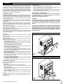
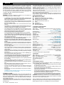
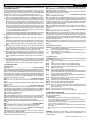
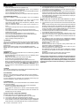
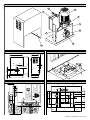
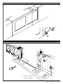
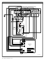
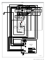
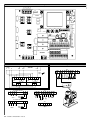
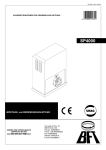
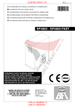
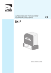
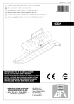
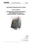
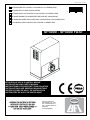
D811229 ver.05 11-10-07 I AUTOMAZIONE PER CANCELLI SCORREVOLI A CREMAGLIERA GB AUTOMATION FOR RAK SLIDING GATES 8 027908 114341 F AUTOMATIONS POUR PORTAILS COULISSANTS Á CREMAILLÉRE D AUTOMATIONENE FÜR SCHIEBEGITTERTORE MIT ZAHNSTANGE E AUTOMATIZACIONES PARA PORTONES CORREDIZOS CON CREMALLERA P ACCIONADOR PARA PORTÖES DE CORRER A CREMALLERA SP4000 - SP4000 FAST ISTRUZIONI D’USO E DI INSTALLAZIONE INSTALLATION AND USER’S MANUAL INSTRUCTIONS D’UTILISATION ET D’INSTALLATION INSTALLATIONS-UND GEBRAUCHSANLEITUNG INSTRUCCIONES DE USO Y DE INSTALACION INSTRUÇÕES DE USO E DE INSTALAÇÃO Via Lago di Vico 44 36015 Schio (VI) - Italy Tel. +39 0445 69 65 11 Fax. +39 0445 69 65 22 www.bft.it e-mail: [email protected] USER’S MANUAL Thank you for buying this product, our company is sure that you will be more than satisfied with the product’s performance. The product is supplied with a “Warnings” leaflet and an “Instruction booklet”. These should both be read carefully as they provide important information about safety, installation, operation and maintenance. This product complies with the recognised technical standards and safety regulations. We declare that this product is in conformity with the following European Directives: 89/336/EEC, 73/23/EEC and 98/37/EEC (and subsequent amendments). 1) General outline The SP4000 - SP4000 FAST controller consists of a strong gearmotor. The motor/reduction gear is an hydrodynamic coupling tipe that allows the gate leaf to start and stop smoothly, in order to avoid high structural stress. The self-braking motor allows the leaf to stop rapidly avoiding uncontrollable inertial sliding movements. The gearmotor is joined to the gate by means of a rack. The control panel is incorporated and comprises: protection fuses, three-phase overload cutout and control unit. The function logic allows various configurations to be set in order to better adapt the automation to the customer’s needs (e.g.: automatic closing, photocells activated on closing, etc.). To change any settings, contact a qualified technician (installer). The irreversible type gearmotor keeps the leaf locked on closing. This way it does not need an electric lock. A manual release system allows the leaf to be opened manually in case of power supply disconnection or inefficiency. The installation must be provided with all the devices needed to guarantee safety of persons, animals and things, according to the provisions set out by the current standards. 2) Safety If correctly installed and used, this automation device satisfies the required safety standards. However, it is advisable to observe some practical rules in order to avoid accidental problems. Before using the automation device, carefully read the operation instructions and keep them for future reference. • Keep children, persons and things outside the automation working area, particularly during operation. • Keep radio control or other control devices out of children’s reach, in order to avoid any unintentional automation activation. • Do not intentionally oppose the leaf movement. • Do not attempt to open the gate manually before to have released the motor by mean of the appropriate key. • Do not modify the automation components. • In case of malfunction, disconnect the power supply, activate the emergency release in order to be able to open the gate manually and request the assistance of a qualified technician. • Before proceeding to any outside cleaning operation, disconnect the mains powers supply. • Keep the sliding guide of the gate, photocell optical components and light signal devices clean. Check that the safety devices (photocells) are not obscured by branches or shrubs. • Check the rack lubrication periodically. • For any direct assistance to the automation system, request the help of a qualified technician (installer). • Have qualified personnel checking the automation system once a year. 3.2) Re-activation • Open the actuator door with the appropriate key. • Insert the release key (fig.2 ref. “C”) in the release screw (fig.2 ref. “V”) and turn it clockwise until it is completely tightened. • Put release key “C” back in its place, close the actuator door and check that the automation operates electrically. • Put the actuator door key away in a safe place known to the operators. 4) MAINTENANCE AND DEMOLITION The maintenance of the system should only be carried out by qualified personnel regularly. The materials making up the set and its packing must be disposed of according to the regulations in force. Batteries must be properly disposed of. WARNINGS Correct controller operation is only ensured when the data contained in the present manual are observed. The company is not to be held responsible for any damage resulting from failure to observe the installation standards and the instructions contained in the present manual. The descriptions and illustrations contained in the present manual are not binding. The Company reserves the right to make any alterations deemed appropriate for the technical, manufacturing and commercial improvement of the product, while leaving the essential product features unchanged, at any time and without undertaking to update the present publication. Fig. 1 C Fig. 2 3) Emergency manoeuvre When the electric supply is disconnected or the automation is faulty, the leaf must be opened manually. 3.1) Activation • Open the front actuator door using the key provided (fig.1). • At the time of opening, a safety microswitch stops the actuator from operating electrically. • Take out the release key (fig.2 ref. “C”) located inside the box and insert it in the release screw (fig.2 ref. “V”) . • Turn the key (fig.2 ref. “C”) anticlockwise until the pinion drive system becomes completely loosen. • This way, the pinion is released and the gate can be operated manually. WARNING - Considering the leaf weight, it is recommended to guide the leaf manually along the entire run, and absolutely avoid to push it in an uncontrolled way. C - SP4000 - SP4000 FAST - Ver. 05 v D811229_05 ENGLISH INSTALLATION MANUAL Thank you for buying this product, our company is sure that you will be more than satisfied with the product’s performance. The product is supplied with a “Warnings” leaflet and an “Instruction booklet”. These should both be read carefully as they provide important information about safety, installation, operation and maintenance. This product complies with the recognised technical standards and safety regulations. We declare that this product is in conformity with the following European Directives: 89/336/EEC and 73/23/EEC, 98/37/EEC (and subsequent amendments). 1) General safety WARNING! An incorrect installation or improper use of the product can cause damage to persons, animals or things. • The “Warnings” leaflet and all “Instruction booklets” supplied with this product should be read carefully as they provide important information about safety, installation, operation and maintenance. • Scrap packing materials (plastic, cardboard, polystyrene etc) according to the provisions set out by current standards. Keep nylon or polystyrene bags out of children’s reach. • Keep the instructions together with the technical brochure for future reference. • This product was exclusively designed and manufactured for the use specified in the present documentation. Uses not specified in this documentation could damage the product and be dangerous. • The Company declines all responsibility for any consequences resulting from improper use of the product, or use which is different from that expected and specified in the present documentation. • Do not install the product in explosive atmosphere. • The construction elements must comply with the Current Standards. The Company declines all responsibility for any consequences resulting from failure to observe good technical practice when constructing closing structures (door, gates etc.), as well as from any deformation which might occur during use. • The installation must comply with the provisions set out by the Current Standards and always respect good technical practice. • Disconnect the electrical power supply before carrying out any operations on the installation. Also disconnect any buffer batteries, if fitted. • Fit an omnipolar circuit breaker or thermal magnetic circuit breaker on the mains power supply, having a contact opening distance equal to or greater than 3 mm. • Check that a differential switch with a 0.03A threshold is fitted just before the power supply mains. • Check that earthing is carried out correctly: connect all metal parts for closure (doors, gates etc.) and all system components provided with an earth terminal. • Fit all the safety devices (photocells, electric edges etc.) which are needed to protect the area from any danger caused by squashing, conveying and shearing. • Place at least one light signal device (blinker), and fix a Warning sign to the structure where it can be easily seen. • The Company declines all responsibility with respect to the automation safety and correct operation when other manufacturers’ components are used. • Only use original parts for any maintenance or repair operation. • Do not modify the automation components, unless explicitly authorised by the company. • Instruct the product user about the control systems provided and the manual opening operation in case of emergency. • Do not allow persons or children to remain in the automation operation area. • Keep radio control or other control devices out of children’s reach, in order to avoid unintentional automation activation. • The user must avoid any attempt to carry out work or repair on the automation system, and always request the assistance of qualified personnel. • Anything which is not expressly provided for in the present instructions, is not allowed. • Installation must be carried out using the safety devices and controls prescribed by the EN 12978 Standard. 2) General outline The SP4000 - SP4000 FAST controller consists of a strong gearmotor. The motor/reduction gear is an hydrodynamic coupling tipe that allows the gate leaf to start and stop smoothly, in order to avoid high structural stress. The self-braking motor allows the leaf to stop rapidly avoiding uncontrollable inertial sliding movements. The gearmotor is joined to the gate by means of a rack. The control panel is incorporated and comprises: protection fuses, three-phase overload cutout and control unit. 14 - SP4000 - SP4000 FAST - Ver. 05 The function logic allows various configurations to be set in order to better adapt the automation to the customer’s needs (e.g.: automatic closing, photocells activated on closing, etc.). To change any settings, contact a qualified technician (installer). The irreversible type gearmotor keeps the leaf locked on closing. This way it does not need an electric lock. A manual release system allows the leaf to be opened manually in case of power supply disconnection or inefficiency. The installation must be provided with all the devices needed to guarantee safety of persons, animals and things, according to the provisions set out by the current standards. The gearmotor (fig.1) comprises : MF) Motor with electric brake G) Hydrodynamic motor/reduction gear coupling R) Reduction gear in oil bath with worm screw/wheel MS) Opening door safety microswitch S) Electromechanical end-of-stroke unit P) Pinion Q) Control panel SB) Emergency release C) Box with lockable door. 3) Technical specifications 3.1) SP4000 - SP4000 FAST Power supply....... : three-phase+N 400V three-phase 230V ±10% 50Hz (*) Motor revolutions.................................................... ....: 1400min-1 (SP 4000) .........................................................................2800 min-1 (SP 4000 FAST) Absorbed power.............................................................................. : 1500W Max absorbed power........................................ : 2.6A (400V); 4.84A (230V) Protection.............................................. : overload cutout wired in the panel Insulation class......................................................................................... : F Reduction ratio.....................................................................................: 1/46 Output revolutions........................................................... : 30min-1 (SP 4000) ............................................................................. 60 min-1 (SP 4000 FAST) Pinion pitch..................................................................: m=6mm z=18 teeth Max leaf weight............................................. : 40000N (~4000kg) (SP 4000) .......................................................... : 10000N (≈1000kg) (SP 4000 FAST) Leaf speed................................................................. : 10.1m/min (SP 4000) ...................................................................... : 20.2 m/min (SP 4000 FAST) Impact reaction......................................................: stop (with electric edge) Reduction gear lubrication....................................................................... : oil Manual manoeuvre................................ : multi-disk mechanical key release No. manoeuvres in 24 hours..........................................: continuous service Control unit.......................................................... : SIRIO TEL with interface Environmental conditions........................................... : from -15°C to +50°C Degree of protection............................: IP X4(Electrical components:IP 54) Dimensions...................................................................................: See fig. 2 Controller weight....................................................................: 850N (~86kg) (*) 230V three-phase power supply available 3.2) SIRIO TEL Power supply (*):....................400 vac three-phase + /230 vac three-phase Mains - low voltage insulation:........................................ > 2MOhm 500Vdc Mains - low voltage dielectric strength:........................................3750Vac 1' Power supply to accessories:..................................................... 24Vac/0,5A Gate-open warning light:.................................................................... 24/3W Blinker:..........................................................................................230V/40W 4) Preliminary checks Check that the gate structure is conform to whatever is prescribed by the current standards, and in particular that: • the gate sliding track is linear and horizontal, and the wheels are suitable for supporting the gate weight; • the gate manual operation can be carried out smoothly along its entire run, and there is no excessive side slipping; • a correct play is provided between the upper guide and the gate to ensure regular noiseless movement; • the gate stops on opening and closing are or can be positioned; • the established position for gearmotor fixing allows the emergency manoeuvre to be carried out smoothly and safely. In the case where the elements checked do not meet the above requirements, proceed to carrying out the necessary corrective actions or replacements. WARNING: Remember that control devices are intended to facilitate gate use, but can not solve problems due to any defects or deficiency resulting from failure to carry out gate maintenance. Take the product out of its packing and inspect it for damage. Should it be damaged, contact your dealer. Remember to dispose of its components (cardboard, polystyrene, nylon, etc.) according to the current prescriptions. D811229_05 ENGLISH D811229_05 INSTALLATION MANUAL 5) Base plate anchoring 1) Identify a suitable position, and check that there are no underground cables or pipes. 2) Arrange for a pit or column near the fixing plate for the various connections, in order to have a single raceway with a 60-80mm diameter reaching the actuator. 3) The anchoring base, which is already assembled (fig. 3), must be positioned with the gear label facing the gate. 4) Dig a hole having the size specified in fig. 3, where to cement the base plate log bolts to fix the actuator with. If the sliding track is already there, digging must be partly carried out in the track foundation casting. This way, should the track sag, the gearmotor base would also lower, thus maintaining the play between pinion and rack (approximately 4-5mm). In order to keep the base plate correct position during installation, it may be useful to weld two iron rods under the track, and then weld the log bolts onto them (fig. 3). 5) Position the base plate according to the mesurement specified in fig. 4. The pinion symbol printed on the base plate must be visible and directed towards the gate. This also ensures the correct positioning of the pipe or the cable channel for electrical connections. 6) Let the single pipe or cable channel provided for electric cables protrude from the base plate. 7) Proceed to casting the concrete. 8) Accurately check that: - The positioning dimensions (fig. 4) are correct, - The base plate to be levelled in both directions, - The 4 stud threads and the base are free from cement. - Let the casting harden. Note: The actuator must be fixed to the foundation base which comprises a steel plate treated against corrosion and the log bolts to anchor the plate to the ground. WARNING: Do not loosen the nuts securing the log bolts. After cementing, use a dynamometric wrench to check that these are tightened with a 70Nm torque. Fig. 5 shows dimensions and holes to be drilled in the actuator base. 6) Gearmotor fixing When the casting has hardened, make all the mains and accessory connection cables go through, letting them protrude from the foundation plate by approximately 1 metre. Observe fig. 6 and proceed as follows: 1) Open the door and unscrew the 4 screws which fix the protective cover to the base (fig. 1 ref. ”C”) using a suitable key. 2) Position the actuator over the plate, and insert all the cables or pipes in the appropriate hole (fig. 6), and the tie rods in the fixing slots. 3) Thread a flat spacer washer, a spring washer and an M12 nut on each one of the four base tie rods. Leave the nuts loose for correct positioning. 4) Fit the four levelling dowels (fig. 7 ref. “G”) and adjust them so as to level (fig. 7 ref. “L”) the actuator, which should be raised by approximately 810mm with respect to the foundation base. 5) Slide the actuator in the appropriate slots, find its final position respecting the measurements specified in fig. 4, and fix the four nuts (fig. 7 ref. “T”) which secure the actuator to the foundation plate and the levelling dowel lock nuts. Note: the rack teeth should mesh with the pinion along their entire width. 7) Arrangement for rack fitting A steel rack having a pitch of m=6mm teeth and cross section of at least 30x30mm must be fixed to the gate. It is usually supplied in 2-metre elements. As far as length is concerned, this must take into account the passage space, the pinion meshing section and also the space for fixing the runners controlling the end-of-stroke. Rack fixing must be suitable for the type of gate used. As an example, this paragraph describes the rack fixing method by means of welded angle bars (fig. 8). WARNING – Welding is to be carried out by a skilled operator wearing all personal protective equipment prescribed by the current safety standards. During welding operations, use suitable screens to protect the actuator from any welding spits. 7.1) Fitting 1) Prepare some rack fixing angle bars using adequately-sized “L” shaped sections. They must be fixed or welded at a distance of approximately 80-100cm. 2) Bring the gate to a fully closed position (or open, if more practical) by hand. 3) Activate the emergency release (See paragraph on “EMERGENCY MANOEUVRE”). ENGLISH 4) Rest the end of one rack element on the control pinion, keeping it levelled (parallel to the track). 5) Rest one angle bar on the rack and secure it with a suitable clamp; while keeping the rack level and lined up with the pinion profile, spot weld the angle bar to the gate and then the rack to the angle bar (fig. 8). 6) Push the leaf by hand as far as the other end of the rack, centre the rack into the pinion teeth, rest one angle bar on the rack, secure it with a suitable clamp, spot weld it to the gate and then weld the rack to the angle bar. 7) While sliding the leaf by hand, position and lightly spot weld the intermediate angle bars (one every 80-100cm). 8) Slide the rack element out of the pinion, and strongly weld the angle bars and the rack. WARNING: Do not weld the joints of the rack elements together. 9) Position another rack element next to the one welded previously. Couple the joints of the two elements by opposing a piece of rack (fig. 9) to keep the correct pitch, and secure everything using suitable clamps. 10)Proceed to welding and positioning all the elements by repeating the procedure described above. 8) Pinion adjustment Having finished fixing the rack, the rack-pinion play must be adjusted as follows, with reference to fig. 10. 1) Slacken the four “G” dowels at the base of the actuator by approximately 4 mm. 2) Check levelling by means of a level. 3) Check that the rack meshes with the pinion all along its width and the leaf stroke. 4) Fix the 4 log-bolts nuts (fig. 10 ref. “T”) which fasten the actuator to the ground. 5) Fix the 4 levelling dowel lock nuts (fig. 10 ref. “G”). 6) Check the slack between pinion and rack along the whole rack length; if necessary, adjust the play between pinion and rack. WARNING – Remember that the life of the rack and pinion largely depends on the mesh. 9) Fitting of end-of-stroke runners These are used to control the opening/closing limit microswitches. They can be directly welded on the rack or fixed by means of screws. When fixed by screws, the runner position can be re-adjusted later. WARNING - The automation must not be electrically operated without the end-of-stroke runners. This operation is to be carried out with the emergency release activated and mains power supply disconnected. 1) If the mains power is already connected, ensure that the automation switch is down. 2) Activate the emergency release as described in the respective paragraph. 3) Push the leaf fully open by hand, and stop it approximately 4-5cm before the required stop point. 4) Connect an ohmmeter to the control unit terminals related to the opening limit switch (SWO) by consulting the paragraph on “Terminal connections”. Check the instrument reading by pushing the end-of-stroke control lever by hand towards the opening direction (the instrument must show interruption of continuity). 5) Position the end-of-stroke runner on the rack and push it against the endof-stroke lever (fig. 11 ref. “P”) until the instrument signals microswitch intervention. 6) After identifying the runner position, fix it by spot welding. In the case of screw fixing, mark the identified position and proceed accordingly. 7) Connect the instrument to the control unit terminals related to the closing limit switch (SWC). Check the instrument reading by pushing the end-of-stroke control lever by hand towards the opening direction (the instrument must show interruption of continuity). 8) Push the leaf fully closed by hand. Stop the leaf by approximately 45cm from the required closing point. If necessary, take into account any clearance (fig.12) or impact device (fig.13 - ref. “CS”) needed, according to the provisions set out by current national standards. 9) Position the end-of-stroke runner on the rack and push it against the endof-stroke lever until the instrument signals microswitch intervention. 10)After identifying the runner position, fix it by spot welding. In the case of screw fixing, mark the position and proceed accordingly. 11)Disconnect the instrument, restore motorised operation (see paragraph on “Emergency release”). Correct electrical limit switch intervention is to be checked after carrying out electrical connections and checking the “DIRECTION OF ROTATION” (see relevant paragraph). If the position is correct, secure the welded runners with sturdy welding, or check that the fixing screws to be well tightened (depending on the chosen fixing way). SP4000 - SP4000 FAST - Ver. 05 - 15 INSTALLATION MANUAL IMPORTANT: In the case where the leaf keeps sliding after the stop command, the moulded end section of the runner (fig. 11 ref. “A”) can be lengthened so as to stop the runner from going past the end-of-stroke point. WARNING! To avoid inefficiency, or damage to the automation, keep always a space of 4-5cm before the required opening/closing end positions (fig. 12). 10) Gate backstops DANGER - The gate must be provided with mechanical backstops both on closing and opening (fig. 12 ref. “F”) in order prevent it from coming out of the upper guide. The mechanical stops must be sturdily secured to the ground, a few centimetres beyond the electric stop point. 11) Electrical installation set-up Lay out the electrical installation as shown in fig. 13, with reference to the CEI 64-8 and IEC 364 provisions complying with the HD 384 and other national standards in force for electrical installation. WARNING – Check the actuator rating. For the 400V three-phase version, connect the mains using a multipolar R-S-T-N+EARTH cable having a minimum cross section of 2.5 sq mm and complying with the current national standards (e.g.: H07RN-F type). For the 230V three-phase version, connect the mains using a multipolar R-S-T+EARTH cable having a minimum cross section of 2.5 sq mm and complying with the current national standards (e.g.: H07RN-F type). Connect the control and safety devices in compliance with the previously mentioned technical installation standards. The mains power supply connections must be kept totally separate from the auxiliary connections. Fig. 13 shows the number of connections and the cross section for approximate lengths of 100 metres; in case of greater lengths, calculate the cross section for the true automation load: The main automation components are (fig. 13): I Type-approved omnipolar circuit breaker with adequate capacity and at least 3 mm contact opening, provided with protection against overloads and short circuits, suitable for cutting out automation from the mains. If not already installed, place a type-approved differential switch with a 0.03A threshold before the automation system QR Control panel and incorporated receiver S Key selector AL Blinker with tuned antenna M Actuator E Electric lock P Control buttons CS Electric edge CC Edge control Fte, Fre Pair of external photocells Fti, Fri Pair of internal photocells CF Posts T 1-2-4 channel transmitter. WARNING! Operator without torque limiter: install the actuator with appropriate safety systems (eg. device type E item 5.5.1 of EN12453:2000 standard) 12) Control panel connections After the appropriate electric cables have been passed through the raceways and fixed to the various automation components in the chosen points, these must be connected according to the indications and diagrams shown in the relevant instruction manuals. Connect the phase, neutral (230V three-phase excluded), and earth (compulsory) cables.The protection (earth) wire, having a yellow/green insulating sheath, must be connected to the appropriately marked terminals provided . The automation device is to be operated after all the safety devices have been connected and checked. Fig. 14-15 shows the wiring diagram of the panel fitted to the actuator. Here follows a description of the terminals to be connected to the control panel (fig.14-15) including the SIRIO TEL mod. unit (fig. 16). Panel N-R-S-T+ EARTH 400Vac ±10%, 50Hz, three-phase panel power supply R-S-T+ EARTH 230Vac ±10%, 50Hz, three-phase panel power supply SIRIO TEL control unit terminal board (fig.16) N.B.: The board is supplied with a series of previously bridged terminals. The jumpers refer to the following terminals: 26-29, 26-30, 26-31, 26-35. If these terminals are not used, leave them bridged. JP1 - THREE-PHASE 400V 1-2-3-4 Three-phase power supply+neutral 400V (1N - 2R - 3S - 4T). 8-9 230Vac output for blinker 40W max. 16 - SP4000 - SP4000 FAST - Ver. 05 JP1 - THREE-PHASE 230V 2-3-4 Three-phase power supply 230V (2R - 3S - 4T). 8-9 230Vac output for blinker 40W max. JP2 10-11 11-12 12-13 14 15 16-17 24Vac (3W) output for gate-open warning light. 24Vac power supply to accessories and safety devices which are not checked. 24VTx power supply only for safety device transmitters which are checked. LOOP1 input for safety device check ring (see fig.5). LOOP2 input for safety device check ring (see fig.5). Second radio channel output for two-channel receiver board (n.o.). Antenna input for radio receiver board (18 signal, 19 braid). 18-19 JP7 20-21-22 23-24-25Outputs for the connection of safety devices which areto be checked (see fig.5). JP4 26-27 START button (n.o.). 26-28 Block button (n.c.). Additional buttons to be connected in series with one another. 26-29 Photocell contact input (n.c.). If not used, leave on. If used while checking, observe wiring diagram in fig.5. 26-30 Opening limit switch (n.c.). If not used, leave bridged. 26-31 Closing limit switch (n.c.). If not used, leave bridged. 26-32 Pedestrian access button (n.o.). 26-33 Open button (n.o.). 26-34 Close button (n.o.). 26-35 IR edge contact input (n.c.). If not used, leave bridged. JP6 1-2 channel radio receiver board connector. 12.1) Check of direction WARNING! Before supplying the system with power, it is compulsory to check the “DIRECTION OF ROTATION” as described below. 1) Activate the release as described in the paragraph on “EMERGENCY MANOEUVRE”. 2) Bring the leaf to the fully closed position by hand (limit microswitch pressed). 3) When the system is supplied with power (control unit door and box open), the SWC LED must be off. If the LED are on, the SWO and SWO limit switch connections must be reversed in the control unit. 4) Bring the leaf to the half-way position by hand. 5) Restore motorised operation (“EMERGENCY MANOEUVRE”) and reposition the box door to close the respective safety contact. 6) Disconnect the mains power supply temporarily to reset the control unit. 7) At the first start command, the control unit always carries out the opening manoeuvre; check the following: a)if the gate moves along the opening direction, the direction of rotation of the actuator is correct; b)if the gate moves along the closing direction, disconnect the mains power supply and invert two phases in the control unit power supply terminal board. 8) Connect the mains power supply and carry out a complete checking cycle. 13) CONNECTION TO SAFETY DEVICES • In case of standard devices with 4 terminals and without self-diagnostic function, the connection can be carried out without verification as indicated in point 13.1. • In case of devices featuring internal self-diagnostic function, refer to point 13.2. • The standard devices with 5 terminals and without self-diagnostic function can be included in the control and self-diagnostic cycle observing the instructions given in point 13.3. 13.1) Safety devices WITHOUT SELF-DIAGNOSIS Connections must be carried out as shown in fig. 18. Keep the Dip-switches 9 and 10 in the ON position (standard setting). The tripping contacts of a group of devices of the same type, must be connected in series with one another. 13.2) Safety devices WITH INTERNAL SELF-DIAGNOSIS Connections must be carried out as shown in fig.18. Keep the Dip-switches 9 and 10 in the ON position (standard setting). The tripping contacts of several devices of the same type, must be connected in series. D811229_05 ENGLISH D811229_05 INSTALLATION MANUAL 13.3) Safety devices without self-diagnosis but with voltage-free EX-CHANGE CONTACTS. We conventionally make reference to a receiving device (RCS- fig.5) with 5 terminals which have the following functions: terminals 1 and 2 are for 24Vac power supply, terminal 3 is a common terminal, terminal 4 is a normally closed contact not in use, terminal 5 is a normally open contact not in use. A) Fig. 19 “A” shows the wiring diagram for connecting the power supply to those receivers and transmitters for which a self-diagnosis is required. B)Fig. 19 “B”. Connection of one or more receivers (photocell) of the same type up to a maximum of four (Dip 9 OFF/Dip 10 ON, photocells only, leave jumped 35-26). For example, if there are two photocells, connect F1 and F2, then interrupt the connection chain by connecting the terminal 4 of F2 to LOOP1 and the terminal 5 of F2 to COM. If only one receiver has to be connected, connection must be made as shown in fig.19 ref.1. If the receivers to be connected are less than four, it is necessary to interrupt the connection chain by performing the connections as shown in fig.19 ref. 2 or 3. If rubber edges instead of photocells have to be connected, use terminal 35-BAR of the control unit. If the devices concerned are rubber edges instead of photocells, use terminal 35-BAR in the control unit (Dip 9 ON/Dip 10 OFF, leave jumped 29-26). C) Connection of one photocell and one rubber edge.(Dip 9 OFF/Dip 10 OFF) D)Connection of two photocells and one rubber edge.(Dip 9 OFF/Dip 10 OFF) When connecting two rubber edges and one photocell, F1 and F2 in fig.19 “D” become 2 rubber edges, and C1 one photocell; invert the connections PHOT and BAR of the control unit with one another.(Dip 9 OFF/Dip 10 OFF) E) Connection of three photocells and one rubber edge. When connecting three rubber edges and one photocell, F1, F2 and F3 (fig.19 “E”) become 3 rubber edges and C1 one photocell; invert the connections PHOT and BAR of the control unit with one another.(Dip 9 OFF/Dip 10 OFF) F) Connection of three photocells and two rubber edges When connecting three rubber edges and two photocells, F1, F2 and F3 (fig.19 “F”) become three rubber edges, C1 and C2 two photocells; invert the connections PHOT and BAR of the control unit with one another.(Dip 9 OFF/Dip 10 OFF) G)Connection of four photocells and one rubber edge. When connecting four rubber edges and one photocell, F1, F2 , F3 and F4 (fig.19 “G”) become four rubber edges and C1 one photocell; invert the connections PHOT and BAR of the control unit with one another.(Dip 9 OFF/Dip 10 OFF) 14) OPERATION LOGIC 14.1) Dip-switch Dip 1 and 2 .......................................................................Photocells (FCH) ON - Excludes photocell operation during gate opening, and immediately reverses movement during the closing phase when the photocell is obscured. OFF - In the case where the photocell is obscured by an obstacle during the closing manoeuvre, the gate is stopped; when the obstacle is removed, the gate reopens. In the case where the photocell is obscured by an obstacle during the opening manoeuvre, the gate is stopped; when the obstacle is removed, the gate continues to open. Dip 3........................................................................ Impulse blocking (IBL) ON - The Start / Start pedestrian impulse has no effect during the opening phase. OFF - The Start / Start pedestrian impulse during the opening phase causes the gate to stop. Dip 4.................................................................... Automatic closing (TCA) ON - Automatically closes the gate after a dwell time set by the TCA trimmer. The automatic closing manoeuvre is activated after the gate has reached the opening end-of-stroke position, after the gate opening time has ended, or after the gate has stopped in the opening phase due to a Start impulse. OFF - Excludes automatic closing. Dip 5 2 or 4 step logic (2P/4P) ON - A Start impulse given during the closing phase reverses the direction of movement, during the opening phase it stops the gate. (Dip-switch OFF). OFF - A Start impulse given while the gate is moving, causes it to stop; the following impulse reverses the running direction. (4-step logic). N.B.: The Start impulse in the opening phase has no effect when Dip-switch 3 is ON. Dip 6 ........................................................................... Pre-alarm (PREALL) ON - The blinker comes on about 3 seconds before the motor starts. OFF - The blinker comes on at the same time as the motor starts. Dip 7 ..............................................................Open/Close command (U.P.) Activates the signals connected to terminals 33-34. ON - Hold-to-run operation: the manoeuvre continues as long as pressure is maintained on the command button. OFF - Separate automatic Open/Close operation: by means of an impulse, it opens the gate if closed and vice versa. ENGLISH Dip 8 .............................. Reduced or normal operation time range (S.TW) ON - TW operation time ranging between 1-90 seconds (TW.PED pedes-trian operation time from 1 to 20 seconds). OFF - TW operation time ranging between 3÷210 seconds (TW.PED pedestrian operation time from 5 to 60 seconds). Dip 9.............................................................. Unchecked photocells (FNV) Activates the photocell control logic. ON - The photocells are excluded from the safety check cycle which is carried out before each manoeuvre; however their logic state is analysed (for connection, refer to the typical method of connecting photocells with continuously active beams). This is used to connect photocells which have not been checked or have internal self-diagnosing systems, and always provide a voltage-free output contact. OFF - The photocells are included in the Ok safety check cycle which is carried out before each manoeuvre. For connection, refer to the enclosed diagrams. Dip 10.................................................................... Unchecked edge (BAR) Activates the rubber edge device control logic. ON - The edge devices are excluded from the safety check cycle which is carried out before each manoeuvre; however their logic state is analysed (for connection, refer to the typical method of connecting infrared edges with continuously active beams). This is used to connect IR edges which have not been checked or have internal self-diagnosing system, and always provide a voltage-free output contact. OFF - The IR edge devices are included in the Ok safety check cycle which is carried out before each manoeuvre. For connection, refer to the enclosed diagrams. 14.2) Trimmer-set functions TW.PED Sets the partial operation time of a sliding gate which is being used for both vehicles and pedestrians. TW Sets the operation time during both the opening and closing phases (adjustable from 3 to 210 seconds). TCA Sets the dwell time, after which the gate closes automatically (from 1 to 120 seconds). 14.3) LED functions The SIRIOTEL control unit is provided with leds which are useful in identifying any anomalies in the system. (DL1) Stays on when supplied with mains power and with F1 fuse intact. (DL2) Comes on when the motor is activated during closing. (DL3) Comes on when the motor is activated during opening. (DL4) Comes on following the Start command or the activation of the first radio-receiver channel. (DL5) Goes off when the block command is activated. (DL6) Goes off when photocells are not aligned, i.e. when obstacles are present. When Dip-switch 9 is OFF, the photocells and related leds are only activated during manoeuvring. (DL7) Goes off when the gate is in the completely open position, if provided with end-of-stroke device. (DL8) Goes off when the gate is in the completely closed position, if provided with end-of-stroke device. (DL9) Comes on at the Start command for pedestrian gate. (DL10) Comes on with manual opening command. (DL11) Comes on with manual closing command. (DL12) Goes off when the pneumatic edge is activated. When Dipswitch10 is OFF, the edge and its related LED are only activated during manoeuvring. (DL13) Comes on when the safety ring is closed. (DL14) Comes on when the safety micro has stepped in. 15) Emergency manoeuvre When the electric supply is disconnected or the automation is faulty, the leaf must be opened manually. 15.1) Activation • Open the front actuator door using the key provided (fig.23). At the time of opening, a safety microswitch stops the actuator (fig.23 - ref. “S”) from operating electrically. • Take out the release key (fig.23 ref. “C”) located inside the box and insert it in the release screw (fig.24 ref. “V”) . • Turn key “C” anticlockwise until the pinion drive system becomes completely loose. This way, the pinion is released and the gate can be operated manually. WARNING - Considering the leaf weight, it is recommended to guide the leaf manually along the entire run, and absolutely avoid pushing it in an uncontrolled way. SP4000 - SP4000 FAST - Ver. 05 - 17 INSTALLATION MANUAL 15.2) Re-activation • Open the actuator door with the appropriate key. • Insert the release key in the release screw (fig.24 - ref. “V”) and turn it clockwise until it is completely tightened. • Put the release key back in its place, close the actuator door and check that the automation operates electrically. • Put the actuator door key away in a safe place known to the operators. 16) AUTOMATION TESTING Before the installation is made fully operational, carry out the following checks. • Check that the overload cutout (fig.22 – ref. “SM”) is set for the rated current absorbed by the motor (400V / 2.8A) -(230V / 4.84A). • Check that all safety devices (limit microswitches, photocells, electric edges, etc.) operate correctly. • Check the tightening torque of the pinion release (emergency release). • Check that the leaf stops within the time and limits provided for by current prescriptions. • Check that the rack-pinion mesh is correct (4mm minimum play). • Check that the opening and closing end-of-stroke runners are correctly positioned and secured. • Check the start and stop operation in case of manual control. • Check the start and stop operation in case of remote radio control. • Check the normal or customised function logic. • Check that all components are tightly secured. • Apply the danger warning label (fig. 23). 17) Control The use of this control device allows the gate to be opened and closed automatically. There are different types of controls (manual, remote, magnetic badge access control, etc.) depending on the installation requirements and characteristics. For the various control systems, refer to the applicable instructions. Explain the correct operation of the automation device to the end users. 18) Maintenance WARNING! Any maintenance operation must be carried out by qualified personnel (see paragraph 2). • Check the play between the pinion and rack (4mm c.a.). Moderately clean and grease the rack. • Always keep the sliding track clean and free from debris. • Occasionally clean the photocell optical elements. • Check the correct tightening torque of the pinion release screw. • When any operational malfunction is found, and not solved, disconnect the mains power supply. When automation is out of order, activate the emergency release (see paragraph “EMERGENCY RELEASE”) so as to put the pinion in neutral and allow the gate to be opened or closed manually. 19) Noise The aerial noise produced by the gearmotor under normal operating conditions is constant and does not exceed 70dB(A). 20) Scrapping Materials must be disposed of in conformity with the current regulations. In case of scrapping, the automation devices do not entail any particular risks or danger. In case of materials to be recovered, these should be sorted out by type (electrical components, copper, aluminium, plastic etc.). 21) Dismantling When the automation system is disassembled to be reassembled on another site, proceed as follows: • Disconnect the power supply and the entire electrical installation. • Remove the gearmotor from its fixing base. • Disassemble the control panel, if separate, and all installation components. • In the case where some of the components cannot be removed or are damaged, they must be replaced. 22) Malfunction: causes and remedies. 22.1) The gate does not open. The motor does not turn. 1) Check that the system is supplied with power (see main switch). 2) Check that the door safety microswitch operates correctly. 3) Check that the overload cutout located inside the control panel has not been activated; if necessary, restore operation using the appropriate button and check current absorption by means of amperometric pliers. 18 - SP4000 - SP4000 FAST - Ver. 05 4) Check that the photocells or electric edges are neither dirty nor engaged nor misaligned. Otherwise proceed accordingly. 5) Check that the electronic equipment is correctly supplied with power. Check that the fuses are not damaged. 6) By means of the control unit diagnosing LEDs (see respective instructions), check that the functions are correct. If not, identify the cause of any fault. If the LEDs show a persistent unwanted start command, check that there are no radio controls, start buttons or other control devices keeping the start contact activated (closed). 7) If the control units does not work, replace it. 22.2) The gate does not open. The motor turns but there is no movement. 1) The manual release was left activated. Restore motorised operation. 2) Check whether the gate is well housed in the mechanical end-of-stroke stops. Release the gate manually, move it from its position and restore motorised operation. Check and correct the position of the end-of-stroke runners to anticipate microswitch intervention. If after electric stoppage there is excessive leaf sliding, check the electric brake air gap, as specified in the motor instruction manual supplied with the product. 3) Check that the gate does not show mechanical defects, as for example wheels blocked, pinion/rack misaligned, etc. 4) If the motor turns, but the leaf is not strong enough to move, check that there are no oil leaks in the coupling, and check the oil level in the hydrodynamic coupling, as explained in the instruction manual for the coupling. 5) Any abundant oil leak may indicate that the hydrodynamic coupling thermal protection has been triggered. Find the hidrodynamic coupling oil plug, the appropriate type of oil and proceed as follows: Disconnect the mains power supply. Remove the box. Remove the actuator from its fixing base and lay it down tilted to the right with the motor in a horizontal position. Rotate the hydrodynamic coupling by hand until it shows the green thermal plug (fig.24 ref. TV) to be replaced. For maintenance and repair, carefully read the hydrodynamic coupling instruction manual supplied with the product, and follow the relevant instructions. Reposition the actuator in the base plate, align and secure it. Refit the box, the doors and then recheck operation. The descriptions and illustrations contained in the present manual are not binding. The Company reserves the right to make any alterations deemed appropriate for the technical, manufacturing and commercial improvement of the product, while leaving the essential product features unchanged, at any time and without undertaking to update the present publication. D811229_05 ENGLISH 56.5 Min. 10 81.5 45 43.5 30 49 350 699 MS Fig. 2 40 0 Fig. 4 245 65 M12 Ø6 0 327 115 40 54 236 120 542 45 187 288 293 160 Piano superiore Top level Oberseite Dessus supérieur Superficie superior 0√7 524 45 185 Lato uscita pignone Pinion exit side Côté sortie de pignon Seite des zahnrades Lato salita piñón 187 √ 194 D811229_05 Fig. 1 MF Q G S P R C SB Fig. 3 52 16 Øp108-Z18 M6 55 0 305 Fig. 5 297 60 133.5 93 SP4000 - SP4000 FAST - Ver. 05 - 39 Fig. 7 D811229_05 Fig. 6 T G L 8 √ 10 L 8 Fig. 9 Fig. 10 Fig. 11 4√5mm Fig. 8 A P T 40 - SP4000 - SP4000 FAST - Ver. 05 L SWO 30 31 SWC COM G 26 COM 30 31 SWO 26 SWC D811229_05 Fig. 12 n. mi n. mi mm 50 mm 50 0m ≥2 m F Fig. 13 CC CS Al CS C Fre M Qr CC Fti CF S Fte 2 m x1m 3x1 mm2 2 P 2 m m 4x1 Fri I CF * 2 mm T 4x1 2 mm 2 2x1 mm 3x1 2 m * * 400V 3~ 5x2.5mm2 230V 3~ 4x2.5mm2 5m x1. 2 58 RG * SP4000 - SP4000 FAST - Ver. 05 - 41 K3 A1 D811229_05 Fig.14 K2 A1 K1 A2 K0 A1 A2 K0 + ~ ~ - M 400V 3~ 5* 4* 3* 2* 1* * 40 39 38 37 45 46 47 42 43 44 48 49 SIRIOTEL 400 26 27 28 29 30 31 32 33 34 35 36 50 51 52 53 N R S T 20 21 22 23 24 25 10 11 12 13 14 15 16 17 18 19 N R S T 400V 42 - SP4000 - SP4000 FAST - Ver. 05 ~ * 7 x 1,5 mm 2 D811229_05 Fig.15 K3 A1 K2 A1 K1 A2 K0 A1 A2 K0 + ~ ~ - M 230V 3~ 3* 2* 1* 5* 4* * 41 40 39 38 37 45 46 47 42 43 44 48 49 26 27 28 29 30 31 32 33 34 35 36 50 51 52 53 N R S T R S T 230V SIRIOTEL 230 ~ 20 21 22 23 24 25 10 11 12 13 14 15 16 17 18 19 * 7 x 1,5 mm 2 SP4000 - SP4000 FAST - Ver. 05 - 43 D811229_05 Fig. 16 41 40 39 38 37 230V S 400V Safety JP5 T1 RV1 IC1 C4 F1 + C7 0.2AT 42 45 43 46 C3 C2 2AT U2 R8 44 47 R32 R31 U1 TWPED 49 DIP function 1 FCH 2 FCH 3 IBL 4 TCA 5 2P/4P 6 PREALL 7 U.P. 8 S.TW 9 FNV 10 BAR C11 R33 ON 1 2 3 4 5 6 7 8 9 10 U4 - + - TCA + + K9 - TW + C37 U5 D20 K8 R105 R104 DL14 F3 U6 COM START STOP PHOT SWO SWC PED OPEN CLOSE BAR MICRO T JP7 BLINK 10 11 12 13 14 15 16 17 18 19 JP2 SCA 1 2 3 4 5 6 7 8 24VAC TX L1 L2 IICAN ANT SHLD 9 Fig. 18 35 BAR 26 COM 13 12 29 PHOT Fig. 17 11 JP6 RICEV K10 20 21 22 23 24 25 K4 JP1 24VAC R5 U7 NAR NCB CFB NAA NCA CFA F2A SIRIOTEL S D13 D16 D17 D19 D18 D14 D15 D26 U8 26 27 28 29 30 31 32 33 34 35 36 53 R7 R U10 K7 52 51 Y1 C8 DL2 DL3 DL4 DL5 DL6 DL7 DL8 DL9 DL10 DL11 DL12 DL13 50 L DL2 C1 F2 48 N + R1 R6 N + U3 SIRIOTEL JP4 Rx FL 1 2 Tx RI JP2 4 S T 230V ~ 8 9 24V 3W 230V 40W JP1 SIRIO TEL 400 1 2 3 4 10 11 12 13 14 15 16 17 18 19 8 9 24V Tx R 3 CH2 JP7 20 21 22 23 24 25 N R S 400V ~ T 230V 40W 44 - SP4000 - SP4000 FAST - Ver. 05 fig.19 ANT. BAR NO NC APRE CHIUDE NO STOP S 24Vac 2 START Rx RI JP1 SIRIO TEL 230 1 PED 2 NO 1 5 SWC 4 NC 3 LOOP2 Tx FL 2 SWO 1 PHOT 5 NC 4 NC 3 ON NO 2 Dip 10 LOOP1 1 ON COM 26 27 28 29 30 31 32 33 34 35 36 Dip 9 5 4 5 29-PHOT 4 26-COM 35-BAR 3 23 5 24 4 24 5 SIRIO TEL 15-LOOP2 4 C 35-BAR 5 29-PHOT 4 26-COM 3 23 5 24 4 20 26-COM 2 21 14-LOOP1 3 1 11 24Vac 12 SIRIO TEL 25 22 B 3 SIRIO TEL 5 3 4 5 3 4 SIRIO TEL F2 1 2 3 4 5 4 5 F1 1 2 3 F1 1 2 3 SIRIO TEL F3 1 2 3 4 5 F2 1 2 F1 1 2 3 4 5 29-PHOT C1 1 2 3 Fig. 20 26-COM 25 E 35-BAR 5 C1 1 2 4 5 1 15-LOOP2 4 26-COM 3 3 3-26 COM / 4-14 LOOP1 F3 1 5 29-PHOT 4 2 25 2 4-14 LOOP1 / 5-26 COM 2 26-COM 3 F3 1 F1 1 4 5 29-PHOT 2 5 3 26-COM 4 2 23 F4 1 F1 1 5 20 5 3 4 29-PHOT 26 C2 1 2 35-BAR 4 3 21 3 2 26-COM 5 F2 1 5 26-COM 4 SIRIO TEL 26-COM 35-BAR 20 3 F2 1 2 25 C1 1 2 3 22 G 4 21 C1 1 2 3 15-LOOP2 C3 1 2 2 24 2 15-LOOP2 D F3 1 4-14 LOOP1 / 5-26 COM 22 TX 2 23 1 12 24VTx 13 F F4 1 24 RX 5 26-COM 4 15-LOOP2 D811229_05 Fig. 19 A 4 5 2 3 4 5 SIRIO TEL F2 1 2 3 F1 1 2 3 Legenda RX: ricevente fotocellule o coste infrarossi. TX: trasmittente fotocellule o coste infrarossi. F1 - F2 - F3 - F4: dispositivi riceventi fotocellule. C1 - C2 - C3 - C4: dispositivi riceventi coste sensibili. key RX: photocell receiver or infrared rubber edges. TX: photocell transmitter or infrared rubber edges. F1 - F2 - F3 - F4: photocell receiving devices. C1 - C2 - C3 - C4: rubber edge receiving devices. Légende RX: récepteur cellules photoélectriques ou barres palpeuses à infrarouges. TX: émetteur cellules photoélectriques ou barres palpeuses à infrarouges. F1 - F2 - F3 - F4: dispositifs récepteurs cellules photoélectriques. C1 - C2 - C3 - C4: dispositifs récepteurs barres palpeuses. Zeichenerklärung RX: Empfangsteil der Photozellen oder Infrarotleisten. TX: Sendeeinheit der Phototellen oder Infrarotleisten. F1 - F2 - F3 - F4: Empfangsvorrichtungen der Photozellen. C1 - C2 - C3 - C4: Empfangsvorrichtungen der Sicherheitsleisten. Leyenda RX: receptor fotocélulas o barras de infrarrojos. TX: receptor fotocélulas o barras de infrarrojos. F1 - F2 - F3 - F4: dispositivos receptores fotocélulas. C1 - C2 - C3 - C4: dispositivos receptores barras sensibles. Legenda RX: ricevente fotocellule o coste infrarossi. TX: trasmittente fotocellule o coste infrarossi F1 - F2 - F3 - F4: dispositivi riceventi fotocellule. C1 - C2 - C3 - C4: dispositivi riceventi coste sensibili. Fig. 21 S C C v SP4000 - SP4000 FAST - Ver. 05 - 45 D811229_05 Fig. 22 400V 3~ 2.2 2.7 3.2 230V 3~ 5,2 6,3 4 Fig. 23 Fig. 24 TV 46 - SP4000 - SP4000 FAST - Ver. 05