1
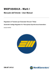
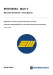
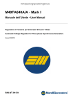
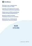
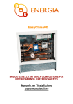
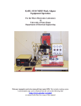
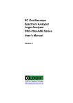
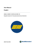
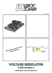
M40FA640A/A - Mark I
User Manual
Automatic Voltage Regulator for Three-phase Synchronous Generators
(Issued: 04.2010)
SIN.NT.015.6
Instruction Manual
Installation • Operation • Maintenance
MARELLI AVR M40FA640A
hanada technology Co.,Ltd.
Page 1
ENGLISH
INTRODUCTION
This Technical Note provides general installation and operating
information exclusively concerning the Marelli Motori regulator
code specified in the document, mounted on the Marelli Motori
synchronous generators specified in the next paragraph
“APPLICATION”.
Before the generator start and any types of regulation
operation, read carefully and completely this Technical Note.
IMPORTANT NOTE: It is not the intention of this document to
cover all the installation or connection diagram variations, nor
does this manual provide information for every possible
contingency. The connection drawings provided with the
generator, the generator user manual and all the technical
information provided by Marelli Motori Technical Personnel can
integrate this Note.
In particular, the connection drawings into this document are
provided only for explanation purposes. They do not cover all
the application cases and not substitute the connection
drawings usually provided with the generator.
Should further information be required, please contact After
Sales Department (see the reference at the end of the page).
SAFETY PRECAUTIONS
WARNING: when the regulation device is
energized (generator running), a lethal
voltage is present at the top panel
(connection side) and at all the parts electrically connected
to it. Furthermore, there are components into the card that can
reach high working temperatures, with high danger for the user
in case of direct contact.
Every wiring and/or mechanical installation
operation on the regulator must be performed only
in generator stop conditions, and only by skilled
personnel. Furthermore, pay attention to wait a time
interval sufficient for the device cooling-down.
Every regulation setting operation must be
performed with generator running in no load
conditions, by skilled personnel, using tools
suitable to assure the user safety (i.e. isolated screwdriver,
protection glasses and gloves).
Marelli Motori is under no liability for any damages which may
occur to the AVR, the plant or the persons, or for lost earnings,
or financial loss, or system stoppages, due to missed out
Technical Note reading (both safety and installation/operating
instructions).
AFTER MARKET DEPARTMENT
MARELLI MOTORI S.p.A.
Tel: +39 0444 479775 Fax: +39 0444 479757
E-mail: [email protected]
Web: www.marellimotori.com
SIN.NT.015.6 – M40FA640A/A
2
Issued 04.2010
ENGLISH
APPLICATION
The voltage regulator type “MARK I”, is suitable for
Synchronous Generators of MARELLI MOTORI make,
MJB series, size range 160-500 frames. This regulator is
proper to operate on machines rated from 10 up to 2000
kVA. The regulator is fully insulated in order to maintain
high reliability also with severe ambient conditions (high
level of humidity, dust, salt atmosphere), and in case of
high vibrations level. The regulator is proper both for single
and 3-phase operation.
DATI TECNICI - TECHNICAL DATA
REGULATION ACCURACY
±0.5%
a regime, per valori di tensione e carico nominali
steady state conditions, for rated Voltage and PF
VOLTAGE DRIFT:
±0.5%
variazione di tensione per variazione Tamb 50°C
of voltage change for 50°C T amb change
RESPONSE TIME:
1 cycle
(20ms-16.6ms)
OPERATING TEMPERATURE:
-30°C ÷ +70°C
EXCITER FIELD RESISTANCE:
3.5Ω (min) ÷ 20Ω (max)
INPUT/OUTPUT DATA:
-SUPPLY VOLTAGE:
-
170 - 277V (50/60Hz)
-POWER SUPPLY:
-
1000 VA (max)
-POWER DISSIPATED:
-
30 W (max)
-VOLTAGE SENSING:
-
170 - 270 / 380 - 415 / 440 - 480 V
(Three or Single Phase Sensing)
-OUTPUT VOLTAGE (DC):
-
80V
(max, servizio continuo)
-OUTPUT CURRENT (DC):
-
8A
(max, servizio continuo)
(max, continuous)
-OUTPUT CURRENT (DC):
-
15 A
(max, in forzamento 1 minuto)
(max 1 minute forcing)
SIN.NT.015.6 – M40FA640A/A
3
Issued 04.2010
ENGLISH
VOLTAGE REGULATOR
M40FA640A/A
MARK I
AMP
FREQ
STAB
SLOPE
ON
VOLT
1
P
Q
2
3
4
OFF
60
Hz
PAR
RED
LED
micro-switches 1-4
YELLOW
LED
A
B
8
6
9
-
+
Varicomp
S6
S5
S4
S3 S2
S1
Three phase
voltage
reference
-
+
N
U
F
U
S
E
Supply
Exciter
stator
TERMINALS
Connection terminals are performed through FAST-ON
terminals. The terminals have to be connected according
the applicable wiring diagram, in order to avoid any
possible mistake in the wiring. The use of FAST-ON
terminals makes any operation on regulator (as
replacement, connection to accessories, setting up)
extremely simple.
POWER STAGE INPUT TERMINALS
“U”, “N” : terminals for power supply
VOLTAGE SENSING INPUT TERMINALS
“S1 - S2”, “S3 - S4”, “S5 - S6” are the terminals for three
phase or single phase voltage sensing.
POWER OUTPUT TERMINALS
“+”, “-”: output terminals (positive, DC, and negative, DC).
SIN.NT.015.6 – M40FA640A/A
4
Issued 04.2010
ENGLISH
CONTROL TERMINALS
“Hz”, “60” : terminals for changing the low speed protection
terminals
“P”, “Q” : terminals for connection of external trimmer
(100kOhm).
“6”, “8”: input terminals for connections of external control
systems (input for D.C. voltage , +/-3 Vdc). The terminal
“
” is to be used only in case of special connections.
TERMINALS for interconnecting with over-boosting
excitation systems
“+”, “-” : output terminals (positive, DC, and negative, DC)
“9” : voltage sensing
EXTERNAL POTENTIOMETER
At the terminals “P” and “Q” an external trimmer (minimum
rating 500mW, resistance about 100kOhm) can be
connected. By acting on such trimmer, it is possible to
obtain a voltage regulation of about +/- 5 % around the
nominal voltage. By using a 200kOhm potentiometer it is
possible to obtain a voltage regulation of about +/- 10 %.
The trimmer is connected anyway (through the regulator) to
the output of the generator and then it represents a live
part.
UNDERFREQUENCY LIMITER
The regulator is provided with internal circuits in order to
reduce the excitation, when running at low speed, in order
to avoid damages to the excitation system of the generator
(i.e. to the regulator, to the exciter field, to the rotating
rectifier, main rotor).
The potentiometer “FREQ” fixes the corner-frequency, that
is the frequency at which the limiter operates. Below that
particular frequency, red LED switches-on and the voltage
of the generator reduces further with speed reduction.
By setting the micro-switch nr. 4 in OFF position, the
voltage reduction is smaller and is close to be proportional
to the speed reduction (voltage reduction is settable by the
potentiometer ”SLOPE”).
ANALOGUE INPUT
The AVR accepts a voltage analogue input of +/-3Vdc
maximum, to control the exciter field of the generator.
This input has to be applied to terminals 6 and 8.
In case of single operation, a maximum change of +/-3Vdc
of the analogue input leads to a maximum change of +/25% of the generator voltage, with respect to the rated
generator voltage.
A value of 0Vdc does not lead to any change in excitation.
SIN.NT.015.6 – M40FA640A/A
5
Issued 04.2010
ENGLISH
The analogue input is usually used for the voltage regulator
control by means of the Marelli power factor regulator, for
parallel operation with the grid.
This input can be also connected to external devices not
made by Marelli, for remote control of the generator voltage
or the excitation during parallel operations (voltage
matching and power factor regulation), as long as those
devices were equipped with suitable outputs (insulated
outputs, and voltage range not higher than +/-3Vdc).
WARNING: in the case of parallel with the grid, and voltage
regulator controlled by an external device by means of the
analogue input, pay attention to the analogue input
voltage value after the load rejection.
In this particular case, in order to avoid any dangerous
generator over-voltages, the voltage value between the
terminals 6 and 8 must be reduced to 0Vdc or to any
values leading to a generator voltage not exceeding the
rated + 5%.
STABILITY SETTING
The voltage regulator is provided with internal adjustable
stability circuits in order to allow operation in a wide range
of applications.
The stability of the regulator can be set on field to adapt it
to the characteristics of the plant and/or the driving engine
(diesel engine, water turbine, gas turbine) in order to obtain
the best voltage response.
To change the stability characteristics of the regulator, it is
necessary to act on the potentiometer “STAB” (for fine
setting of stability).
An additional coarse setting of stability can be achieved by
means of the micro-switches number 1 e 2.
DROOP KIT DEVICE
The device is included in the voltage regulator, to allow
parallel operation between similar generators: the device
permits to share correctly the total reactive power required
by the load among all generators operating in parallel.
The device is composed by an external current transformer
(which senses the current in phase “W”) and the internal
“droop” circuit of the regulator. The C.T. is placed on phase
“W”; the phases “U” and “V” have to be connected to
terminals “S1” and “S2”.
The voltage regulator is provided with input terminals
(terminals “A” and “B”) for easy connection to an external
current transformer. Such terminals are normally shorted
by a connection bridge, when the generator is used in
single operation.
If the voltage is increasing as the load increases, it is
necessary to reverse the leads of the current transformer at
the terminals A-B.
SIN.NT.015.6 – M40FA640A/A
6
Issued 04.2010
ENGLISH
OVER-EXCITATION LIMITER
This function permits to limit the over-excitation due to
particular load conditions that could cause the generator
damage.
As soon as the excitation voltage rises over a certain
threshold, set by means of the potentiometer AMP, for a
time larger than the limiter time delay, the over-excitation
limiter steps-down the excitation voltage to the threshold
value.
Limiter time delay depends on the amount of the over-load:
more the over-load arisen, quicker the limiter action.
Limiting the excitation voltage, the generator excitation
level decreases, partially or totally, depending on the overload occurred. In case of excitation shutdown due to the
limiter, the de-excitation condition could be not maintained.
WARNING: Even if correctly set, this device does not
substitute external systems protections, it is only a
completing device.
WARNING: in case of generator paralleled with the
grid, an over-excitation condition detected by the
limiter can lead to a generator excitation shutdown,
with risk of loss of synchronism.
LIMITER SETTING:
for a quicker limiter setting, it is possible to momentarily
disable the time delay, by means of the micro-switch 3 (see
also the next paragraphs).
In order to properly set the limiter, please apply the
following procedure:
when the generator is running at the rated speed,
apply the maximum desired load;
select position OFF for the micro-switch 3;
carefully rotate counter-clockwise the potentiometer
AMP, until the yellow LED lights up and the generator
voltage decreases to a stable value, lower than the
rated voltage;
carefully rotate clockwise AMP until the yellow LED
switches-off; the generator voltage must recover the
rated value;
select position ON for the micro-switch 3.
If the procedure is properly carried out, the excitation
voltage threshold is set to a value 15-20% higher than the
excitation voltage at the maximum desired load, previously
applied.
Time delay depends on the amount of the over-load
occurred: it can range from 10s minimum to some minutes
maximum.
SIN.NT.015.6 – M40FA640A/A
7
Issued 04.2010
ENGLISH
USE OF POTENTIOMETERS
VOLT - potentiometer to change the output voltage of
the generator:
Normally the internal potentiometer VOLT allows possibility
of adjusting the voltage in a wide range (i.e. between 200
and 560 V); to obtain a finer possibility of voltage setting or
to adjust the voltage from the control panel, or in order to
limit the voltage range, an external potentiometer can be
connected to the terminal “P” and “Q” (resistance about
100kOhm, 500mW, to obtain +/- 5% voltage regulation).
⇒ increases voltage
FREQ - potentiometer to change the low speed
protection:
usually it is set at the factory in order to reduce the
excitation when speed becomes lower than 90% of rated
speed at 50 Hz. By removing the bridge which normally
shorts the terminals “Hz” and “60”, the speed protection
acts properly for 60 Hz operation.
By acting on potentiometer FREQ it is possible to adjust
further (in case should it be necessary) the frequency at
which the low-speed protection is effective.
⇒ decreases frequency of intervention
AMP - potentiometer to change the over-excitation
limiter:
it permits to set the excitation voltage threshold of the overexcitation limiter.
The default setting of this potentiometer is at the maximum
excitation voltage threshold.
⇒ increases the over excitation threshold.
STAB - potentiometer to change stability:
by rotating it clockwise stability increases, but response
time becomes larger.
⇒ increases response time, increases stability
SLOPE - potentiometer to change the low speed
protection characteristic slope:
with the micro-switch 4 OFF, this potentiometer allows to
increase or decrease the under speed ramp slope, and set
the voltage droop for a fixed reduced speed.
⇒ decreases the voltage droop for a fixed frequency
intervention.
PAR - potentiometer to change the droop
This potentiometer allows to change the voltage droop in
load conditions.
⇒ the droop increases
SIN.NT.015.6 – M40FA640A/A
8
Issued 04.2010
ITALIANO
ENGLISH
USE OF MICROSWITCHES
To change the stability characteristics of the regulator, it is
possible to use the micro-switches.
In such a way it is possible obtain changes in the transient
response of the regulator.
Micro-switch 1
ON
Transient response becomes faster
Micro-switch 2
ON
Transient response becomes faster
Micro-switch 3
ON
OFF
Solo per taratura rapida limitazione di sovraeccitazione: toglie il tempo di intervento della limitaz.
Only for quick setting of the excitation limiter: it permits to disable the normal limiter time delay
Micro-switch 4
ON
OFF
Protezione bassa frequenza con pendenza V/f tarabile (fare anche riferimento al potenz. “SLOPE”)
Low speed protection with V/f slope adjustment (see “SLOPE” potentiometer)
FUSE
The voltage regulator is provided with an internal protecting
fuse (which acts in case of faults on the regulator or very
large overloads on exciter circuit).
EMI SUPPRESSOR
The AVR is provided with an internal Electromagnetic
Interference filter: this interference suppression system
permits to obtain compliance with relevant EMC standards
on MARELLI MOTORI generators.
SIN.NT.015.6 – M40FA640A/A
9
Issued 04.2010
ENGLISH
12 TERMINALS + AUX. WINDING
SIN.NT.015.6 – M40FA640A/A
10
Issued 04.2010
ITALIANO
ENGLISH
12 TERMINALS + OVER EXCITATION DEVICE
SIN.NT.015.6 – M40FA640A/A
11
Issued 04.2010
ITALIANO
ENGLISH
6 TERMINALS + OVER EXCITATION DEVICE
SIN.NT.015.6 – M40FA640A/A
12
Issued 04.2010
ITALIANO
ENGLISH
6 TERMINALS + AUX. WINDING
SIN.NT.015.6 – M40FA640A/A
13
Issued 04.2010