1
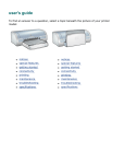
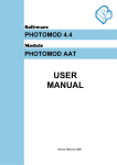
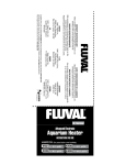
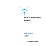
STEREO CAMERA MARK II User Manual Contents Introduction Who should read this document What is in this document What is included Warranty and Support Information Warranty Information Disclaimer and Limitation of Liability Shipping Damage 4 4 4 4 5 5 5 5 Support Information 5 Troubleshooting Getting Support 5 5 Service Locations 6 Safety Guidelines 8 Laser Pointers CAE Stereo Camera Overview Features – Rear View Features – Front View The LCD screen display Technical Specifications Mechanical Specifications Environmental Battery Battery Charger Power Source External DC Power Source Internal DC Power Source User Interface Laser Pointers Flash Digital SLR Camera Monopod General Operating Instructions Check the Camera batteries Prepare the Face Set Out Control Points Set up the Camera Take the photographs 8 9 9 11 12 13 13 13 13 13 13 13 14 14 14 14 14 14 15 15 16 16 18 18 Transferring Digital Images and Starting a New Sirovision Project 23 Removing and Installing the Batteries 24 Removing the Batteries Installing the Batteries 24 24 Performing Preventive Maintenance 25 Inspecting the camera shell and protective glass 25 2 Cleaning the LCD screen Cleaning the Protective Glass Cleaning the shell Glossary 25 26 26 27 3 Introduction CAE Stereo Camera Mark II™ is a second generation remote sensing system primarily used to map geological features and interpret geotechnical characteristics. The CAE Stereo Camera application controls the lasers, ambient lighting and battery life. CAE Stereo Camera allows you to maintain a 3D image database of the mine structures (ground conditions), lithology (rock types) and geological visualizations. Who should read this document Personnel who use CAE Stereo Camera should read this document. What is in this document This document contains the following Stereo Camera information: Warranty and Support Information Service Locations Safety Guidelines CAE Stereo Camera Overview Technical Specifications Opertaing Instructions What is included Stereo Camera is sold with the following components. 1 Rigid carrying case 1 Monopod 2 Lithium Ion Batteries 1 Dual Bay battery charger with accessories 1 Power Supply Unit (PSU) 4 Warranty and Support Information Warranty Information Disclaimer and Limitation of Liability The Stereo Camera comes with a 30-day limited warranty. For details, refer to “Clause 9 of the Warranty contained in the CAE Mining Stereo Camera General Terms and Conditions”. CAE Inc. assumes no responsibility for any damage, loss or other claim incurred by an end user or any third party arising or resulting from the use of this instrument or its associated software. Shipping Damage Each CAE Stereo Camera is inspected before shipment. As soon as the unit is received from the carrier, and before operation, inspect the unit for damage that may have occurred during shipment. If any damage is found, file a claim promptly with the carrier and notify CAE immediately. Support Information If you have any questions or need assistance with your CAE Stereo Camera, contact the nearest CAE Mining Service Location. To find the CAE Mining Service Location nearest you, consult the list of Service Locations on page 6. Troubleshooting Problem Verify that Can’t turn the camera on At least one lithium battery is in the camera and charged Batteries are correctly seated Can’t turn the camera off The Power ON/OFF button was pressed and held down for at least 4 seconds. Blurry image There are no fingerprints or dirt on the protective glass. Getting Support When calling for support, please have on hand the following CAE Stereo Camera information: 5 MFG Part number and Serial Number: You will find these numbers on the nameplate located on the bottom of CAE Stereo Camera. The MFG Part Number is alphanumeric and the Serial Number is numeric. Service Locations CAE Mining has a global network of regional offices that sell, implement and support our technology in every mining region of the world. No matter where our customers are located, CAE Mining has highly trained professionals ready to meet their needs. CAE Mining Canada Inc. In Québec : 3200 rue Guénette Saint-Laurent, Québec Canada H4S 2G5 Tel : +1-514-341-6780 [email protected] cae.com/mining In Ontario: 866 Newgate Avenue, Unit 2 Sudbury, Ontario Canada, P3A 5J9 Toll-free: 1-800-240-6941 Tel: +1-705-688-0101 [email protected] [email protected] Datamine North America Inc. 10901 W Toller Drive #205 Littleton, Colorado 80127 United States Toll-free: 1-800-499-7877 Tel: +1-303-985-7713 [email protected] CAE Mining International Limited Includes Cement and Industrial Minerals Unit A, Underwood Business Park Wookey Hole Road, Wells Somerset BA5 1AF United Kingdom Tel: +44-1749-683350 [email protected] CAE Datamine Chile S.A. Santa Magdalena, 75 Oficina 903, Providencia Santiago 751-0038 Chile Tel: +56-2-334-5952 /+56-2-231-8063 [email protected] CAE Mining Corporate Limited (Cement and Industrial Minerals) Unit A, Underwood Business Park Wookey Hole Road, Wells Somerset BA5 1AF United Kingdom Tel: +44-1749-683350 [email protected] CAE Datamine Peru S.A. Av. Jorge Basadre, 592 Of. 703 Torre Azul, San Isidro Lima 27 Perú Tel: +51-1-222-6000 [email protected] CAE Datamine International Ltd. India Branch Office 601, Elegance Tower Jasola District Centre New Delhi - 110025, India Tel: +91-11-2694-8393 /+91-11-2697-5970 [email protected] CAE Mining Brasil Ltda. Alameda da Serra, 360 - 7• Andar 34000-000 - Nova Lima - MG - Brasil Tel: +55 31 3264-9377 [email protected] Datamine International Limited Kazakhstan Branch Office 201, 2 Lenin Street 100012, Karaganda Republic of Kazakhstan Tel: +7 7212 425138 [email protected] 6 CAE Mining South Africa (Pty) Limited 8, Bentley Office Park Corner Bevan & Wessel Rd Rivonia 2128 South Africa Tel: +27-11-253-3360 [email protected] CAE Mining Australia Pty Limited Level 3, 41 - 43 Ord Street West Perth, Western Australia 6005 Australia Business Office: Level 15, 120 Edward Street Brisbane, Queensland 4000 Australia Tel: +61-8-6462-0900 +61-7-3220-0670 [email protected] 7 Safety Guidelines The following icons are used throughout the manual to alert the user of a possible or certain risk to individuals or the equipment. ALERTS THE USER OF A HAZARD POSING A RISK OF PHYSICAL INJURY TO THE USER OR BYSTANDERS. ALERTS THE USER OF A HAZARD POSING A RISK OF DAMAGE TO EQUIPMENT. The light bulb icon is used to add details for optimal use of the tool. Laser Pointers CAE Stereo Camera is equipped with four (4) Class 3R laser pointers. The Class 3R lasers are Flex 365 nm 5mW dot, and represent a small risk of eye damage within the time of the blink reflex. Avoid direct eye exposure. Even low-power lasers can cause permanent eye damage. Staring into such a beam for several seconds would most likely cause damage to a spot on the retina. For your safety and the safety of those around you, ensure you comply with the following safety guidelines when operating CAE Stereo Camera with the laser pointers turned on to take photos or to perform maintenance tasks: Before turning on the laser pointers, ensure that they are pointed away from yourself and others Never look directly into a laser pointer Never direct a laser pointer at another person Follow the same rules for direct reflections of laser light originating from reflective surfaces WARNING! RISK OF PERMANENT EYE INJURY. NEVER STARE DIRECTLY INTO THE LASERS OR DIRECT THE LASER TOWARD ANOTHER PERSON. LASERS CAN CAUSE PERMANENT EYE DAMAGE. 8 CAE Stereo Camera Overview This section describes the stereo camera features as well as the information on the touchscreen. Features – Rear View Handles – The camera is equipped with three handles: a top-mount handle, and two side-handles to steady the camera when capturing digital images. LCD screen bezel – The bezel holds the screen in place with four screws. LCD screen – The screen is a Liquid Crystal Display with a multi-coated toughened glass. Shutter Release Button – The shutter release button is located on the right handle when the user is facing the LCD touchscreen. Pressing down on the shutter release button triggers the capture of the digital image. Figure 1: Rear View Battery Compartments and Rechargeable Lithium Ion Batteries – The camera is equipped with two rechargeable Lithium Ion batteries that, when fully charged, power the camera when an external power source is not available. The batteries are installed in compartments located in the lower left and right corners of the camera. ON/OFF Power Button – The ON/OFF power button is installed in the camera shell near the lower right-hand corner of the LCD touchscreen bezel. Pressing the button once powers on the camera, pressing the button a second time and holding it down 4 seconds powers off the camera. A blue ring on the button illuminates to indicate the power is on. 9 Cable Port and Cable Port Cover – The cable port provides connectors to attach external cables to the CAE Stereo Camera. The port is equipped with a USB cable connector, an Ethernet cable connector, and a DC power-in cable connector to connect an external power source. The port is capped with a plastic cover to prevent dust migration when no cables are connected. Monopod Adaptor Bracket – The underside of the camera is equipped with a bracket to attach the camera to a monopod. Mounting the camera on a monopod allows the camera to pivot to capture images close to floor and roof range. 10 Features – Front View The following features are shielded from the weather, water and dirt by protective windows. Ambient Lighting Units – The camera is equipped with two (2) LED ambient lighting units, one on each side of the camera flash. The ambient lighting units provide lighting for the setup of the camera. The units momentarily shut off when the camera flash is triggered. Digital Camera and Lens Assemblies – Two digital camera and lens assemblies are installed in CAE Stereo Camera. Each camera and lens assembly is mounted on a turntable that allows horizontal adjustment of the camera angle. The cameras are controlled by a Camera Control Board in the camera shell. Flash Unit – A single flash unit provides the lighting required to capture the digital image. The flash unit is mounted inside the camera shell between the cameras. Laser Pointers – Four laser pointers (one above and below each ambient lighting unit) define the corners of the image field. The laser pointers are aligned so that each one defines the opposite corner of the image field (for example, the upper, left laser pointer defines the lower, right-hand corner of the image field). FIGURE 2: FRONT VIEW 11 The LCD screen display When the Stereo Camera Mark II is turned on, the LCD screen displays the current digital SLR camera settings. FIGURE 3: DIGITAL SLR SETTINGS SCREEN DISPLAYED ON START UP. Below the LCD screen there are 4 buttons: REVIEW Press this to review the left and right photographs that have been captured. DEL Delete the currently displayed stereo pair of photographs. BK Scroll backwards through captured photographs. FW Scroll forward through captured photographs. 12 Technical Specifications Mechanical Specifications Physical Dimensions: Shell Material: Chassis Material: Protective Glass Material: Shipping Weight: Shell Color: ~ 770 x 280 x 280 (mm) Polyurethane Aluminum sheet Lexan for ambient lighting and laser pointers and Fused Silica DLC for camera lenses ~ 9 kg (without carrying case) Orange and Gray Environmental Temperature Range: Weatherproof Rating: Humidity: -10°C to +50°C Splash resistant 95% non-condensing Output Voltage: Required Charge Voltage: Battery type: Battery capacity: 14.4 V dc 16.8 V dc Lithium Ion Pack >= 6270 mAh Battery Battery Charger Power Source Voltage Output: Current: 24 V dc required for battery trickle charge 2.7 amps External DC Power Source Voltage Output: Current: 18 V 12.2 A Internal DC Power Source Voltage Output: Voltage Input: Power: 12 V dc @ 7 A (max), 5 V dc @ 10 A (max), 3.3 V dc @ 10 A (max) 2 chargeable Lithium Ion Batteries 14.4 V dc OR 18 V dc 100 W (max) 13 User Interface Resolution: Backlight: Touch Screen: LCD, 800 x 480, 18 bit (6 bits/color) LED, 12 V dc N/A Laser Pointers Wavelength: Beam Power: Voltage: 650 nM 5 mW 5 V dc Type: Voltage Input: Current: Nikon SB910 5 V dc Limited to 10 A Flash Digital SLR Camera Models: Voltage: Power: Nikon D5100 with Nikkor 20mm F1:2.8 D lens (16 megapixels) 12 V 3.8 W, 6 W Make: Model: Manfrotto 681B Purpose: Industry: Location of use: Host Interfaces: Stereo imaging data collection Mining In underground mines USB 2.0 Ethernet (gigabit) ~ 16 GB Monopod General Image storage space: 14 Operating Instructions The capture of underground stereo photographs using the CAE Stereo Camera Mark II is designed to be quick and accurate and to cause minimum disruption to the underground cycle. FIGURE 4 : THE UNDERGROUND MINING CYCLE In order to obtain the best results, it is recommended the following process be completed. Check the Camera batteries Prepare the face Set Out Control Points Set up the Camera Take the photographs Check the Camera batteries Before leaving to capture images: 1. Remove the camera from the carrying case. 2. Open the battery compartments and pull batteries out half-way. 3. Verify that the batteries in the camera are fully charged (see Figure 5). 15 FIGURE 5: LOCATION OF BAR GRAPH ON BATTERY 4. Push the batteries back into the battery compartments. (see Installing the Batteries on page 24). 5. Ensure the window protecting the camera lenses is clean. (To clean the protective glass, refer to Cleaning the Protective Glass on page 26.) 6. Put the camera back in its carrying case and close the case securely for transport. Prepare the Face CAE Stereo Camera Mark II is used to capture rounds of the rock face. It is preferable to wash the face to remove dust. This reveals the structure and mineralogy to enable the creation of 3D images. This process allows the mine to maintain a 3D image database of the rock mass structures (discontinuities), lithology (rock types), and geological visualizations. Set Out Control Points In underground applications it is highly recommended to survey at least 4 control points on the rock face. There are two commonly used methods: The Four Control Point Method Place 4 control points in a ‘kite’ shape on to the face wall. Some users use a long pole with a paint spray can attached to apply the paint marks whilst remaining within the safe zone underneath the shotcrete. 16 FIGURE 6: FOUR CONTROL POINTS PLACED IN A ‘KITE’ DISTRIBUTION ON THE FACE WALL The Six Control Point Method 1. Whilst remaining underneath shotcrete, apply 3 paint marks (control points) on the LEFT side wall in a triangular shape. These marks should be easily distinguishable and have a center for the surveyors to pick up. They should also be numbered so they can be easily identified in the survey data (see Figure 7). 2. Apply a second (2nd) set of 3 paint marks (control points) on the RIGHT face or the side wall also in a triangular shape, totaling 6 control points. These should also be numbered clearly. 17 FIGURE 7: CONTROL POINTS Set up the Camera 1. Once you are on location: a. Open the carrying case. b. Flip the camera face down in the carrying case to keep the protective glass clean. c. Take the monopod and screw it into the mounting bracket on the bottom of the camera. d. Remove the camera from its carrying case. – CAE Stereo Camera Mark II is ready for use. Take the photographs Important Information CONTROL POINT IMAGES Make sure to capture the control points inside the red laser pointers which delineate the four corners of the photographs. These control points must be visible within the 3D images so that they can be georeferenced. NUMBER OF IMAGES IN A ROUND There is no set number of images that have to be taken in a round. You can take as little as 1 or as many as required to capture the full surface of the subject matter 18 (typically 4 to 6 images). Each image captured must overlap adjacent images by at least 50%. ANGLE TO THE ROCK FACE Place the camera as perpendicular to the rock face as possible. Below is an example where 4 stereo pairs are used to capture the back walls: Shooting the face wall – Stand in the middle of the heading underneath the shotcrete and point the camera at the face wall at 90 degrees. Shooting the left wall – Stand as far to the right of the heading and point the camera in to the left corner where the face wall and left wall merge, capturing 50% overlap between this stereopair and the face wall stereopair. Shooting the right wall – Stand as far to the left of the heading and point the camera in to the right corner where the face wall and right wall merge, capturing 50% overlap between this stereopair and the face wall stereopair. Shooting the ceiling - Stand in the middle of the heading and point the camera upwards capturing where the face wall and ceiling merge, capturing 50% overlap between this stereopair and the face wall stereopair. Procedure Below is an example of capturing the back walls of a heading with four overlapping stereopairs of photographs: 1. 2. 3. 4. Face wall (red) Ceiling (yellow) Right wall (green) Left Wall (brown) 19 FIGURE 8: FOUR STEREOPAIRS COVERAGE DELINEATED BY DIFFERENT COLOURED RECTANGLES. 1. Place the camera underneath the shotcrete but as close as possible to the face wall. Place the camera as perpendicular to the rock face as possible. You should take the photgraphs from as short a range as possible whilst remaining underneath shotcrete for safety. 2. Press the power button once to power on the camera – a blue ring around the button lights up to indicate the power is on. NOTE: Pressing the power button a second time and holding it down for 4 seconds, powers off the camera. 3. Press the button on the left panel of the unit, accessed by holding the left handle to turn on ambient lighting, if desired. Ambient lighting is not required to capture an image, but ambient lights or headlamps will not interfere with the image quality. 4. Press the button on the left panel of the unit, accessed by holding the left handle to turn on the four red laser pointers. These laser pointers point in to the 4 corners of the area that will be captured by the left and right photographs (stereopairs) , so they are there to help you make sure you get 50% overlap between adjacent stereopairs. 20 WARNING! CLASS 3R LASERS RISK OF PERMANENT EYE INJURY. NEVER STARE DIRECTLY INTO THE LASERS OR DIRECT THE LASER IN SOMEONE’S DIRECTION. LASERS CAN CAUSE PERMANENT EYE DAMAGE. 5. Set the laser pointers to the desired position by tilting the camera up or down. First capture – align bottom laser dots at approximately the junction of the face and the floor, include some wall, if necessary. Identify a feature half way (50%)up the wall between the bottom and top laser dots as displayed in Figure 9. Capture the area inside the red rectangle. FIGURE 9: ALIGNMENT OF LASER DOTS – IMAGE 1 6. Second capture – align bottom laser dots with the feature identified in the first shot. Again, identify a feature 50% of the distance from the bottom to the top laser dots (see Figure 10). Essentially you are capturing 50 % overlap between the red and yellow rectangles. 21 FIGURE 10: ALIGNMENT OF LASER DOTS – IMAGE 2 7. Third capture – right wall a. Camera placement – move the camera as far to the left as you can go whilst remaining underneath the shotcrete for safety but so that you can obtain as close to a perpendicular angle in to the rock face as you can get.. Point the camera in to the right corner, making sure you get 50% overlap with the face wall ( green and red rectangles in Figure 8 b. Overlap with ceiling – if you have not been able to get 50% overlap with the celling (yellow rectangle) in the last shot, rotate the camera upwards and capture another stereopair with 50% overlap between the ceiling (yellow) and the right wall ( green). 8. Fourth capture – left wall c. Camera placement – move the camera as far to the right as you can go whilst remaining underneath the shotcrete for safety but so that you can obtain as close to a perpendicular angle in to the rock face as you can get.. Point the camera in to the left corner, making sure you get 50% overlap with the face wall ( brown and red rectangles in Figure 8 d. Overlap with ceiling – if you have not been able to get 50% overlap with the ceiling ( yellow rectangle) in the last shot, rotate the camera upwards and capture another stereopair with 50% overlap between the ceiling (yellow) and the left wall (brown). 9. Power off the camera, remove the monopod and put the camera back in the carrying case. 10. Move to the next location. 22 Transferring Digital Images and Starting a New Sirovision Project Materials needed USB drive Procedure 1. Create two new folders on your computer named ‘LEFT’ and ‘RIGHT’. 2. Insert the USB lead in the USB port (see Figure 1) of the CAE Stereo Camera with the other end connected to your computer. 3. Two camera folders will appear on your computer, one for the left and right cameras. Drill down in to the DCIM folder and you will see a subfolder called ‘LEF’ for the left camera and ‘RIG’ for the right. 4. Copy the left camera images in to the folder ‘LEFT’ and the right images in to the folder ‘RIGHT’. 5. Remove the USB drive from the USB port. 6. When you start a new ‘CAE Stereo Camera Mark II’ project in the Sirovision software, you will be asked to browse to the location of the LEFT and RIGHT folders from which to load the images from. No manual renaming of the image files are necessary. Once the New Project Wizard knows the location of the LEFT and RIGHT folders, it automatically renames the images with a prefix of ‘LEF_’ and ‘RIG_’ accordingly. 7. The software then automatically pairs the left and right images together and applies calibration data. 8. The stereopairs are then loaded and ready to be processed in Project Explorer. 23 Removing and Installing the Batteries Removing the Batteries Materials needed N/A Procedure To remove the camera batteries, as follows: 1. Power the camera off. 2. Open the battery compartment doors by sliding the door latches inward and swinging the doors down. 3. Grip the battery by its pull tab, and pull the battery out of the battery compartment. Installing the Batteries Materials needed N/A Procedure To install the camera batteries, do the following for each battery: 1. Power the camera off. 2. Open the battery compartment door by sliding the door latch inward and swinging the door down. 3. Holding the battery so the electrical connector is directed toward the camera and the label is facing up, insert the battery into the battery compartment until their electrical contacts are seated in place. 4. Close the battery compartment door and slide the door latch outward to lock. 24 Performing Preventive Maintenance Inspecting the camera shell and protective glass Inspect the camera shell and protective glass for signs of wear or physical damage every time you use it: 1. Look for cracks or holes in the shell and protective glass. 2. Inspect the protective glass for signs of dust inside the shell. – Dust on the inside of the protective glass is an indication that the gasket is not sealing properly in that area. Cleaning the LCD screen Materials needed Clean, dry and soft lint-free cloth Water or 50-50 mixture of isopropyl alcohol and water that contain no impurities Procedure To clean your CAE Stereo Camera LCD screen: 1. Gently wipe the display with a soft dry lint-free, cloth. 2. If you see a scratch-like mark on your display, wipe or dust the stain gently with a soft dry, lint-free cloth. 3. If the stain persists, moisten a soft lint-free cloth with water or a 50-50 mixture of isopropyl alcohol and water. ISOPROPYL ALCOHOL IS A FLAMMABLE LIQUID. DO NOT USE THIS CLEANER NEAR AN EXPOSED FLAME OR WHEN THE CAMERA IS POWERED ON. 4. Wring out as much of the liquid as you can. 5. Wipe the display again. Do not let any liquid drip onto the camera. 6. Let the touchscreen dry. Anti-static LCD cleaning cloths and Kim Wipes are acceptable alternatives. 25 Cleaning the Protective Glass Materials needed Clean dry lint free cloth Glass cleaner Procedure 1. With a dry lint-free cloth, remove dirt or fingerprints from the lens by wiping it in a circular motion. If dirt is persistent, remove with lens cleaning fluid. Always drip the fluid onto the cloth and then wipe the lens; never pour fluid directly onto a lens. 2. If dirt persists, drip glass cleaner onto the cloth, and then wipe the lens using a circular motion. Cleaning the shell Materials needed Clean lint free cloth Glass cleaner Procedure 1. Wipe down with clean lint free cloth. 2. If the shell is still dirty, moisten rag with glass cleaner and wipe down again. 26 Glossary Angle of slope Also called tilt or slope angle, the angle of slope is the angle of the primary inclined opening, connecting the surface with the underground workings Back In mining terms the back is the ceiling, also called the roof. Control point: A position in a horizontal and/or vertical control system identified on a photograph and used to georeference the data displayed on that photograph. DC Direct current (DC) is the unidirectional flow of electric charge. Direct current is produced by such sources as batteries, thermocouples, or solar cells. DCL Diamond Like Coating. On CAE Stereo Camera, the protective window for the lenses is made of Fused Silica DCL. Discontinuity Drift In mining, a drift is a horizontal passage underground. A drift follows the vein, as distinguished from a crosscut that intersects it, or a level or gallery, which may do either. Drive In mining, a drive is a tunnel or level which is in or parallel to a mineralized lode or vein. It is distinct from a crosscut, which only gives normal access to the lode. Drive, to To excavate horizontally, or at an inclination, as in a drift, or entry. Distinguished from sinking and raising. End wall Also known as face. See Face for the definition. Ethernet Ethernet is a packet based transmission protocol that is primarily used in LANs. Ethernet is the common name for the IEEE 802.3 industry specification and it is often characterized by its data transmission rate and type of transmission medium. Rock mass structure An abrupt change in the physical properties of adjacent materials in the Earth's interior. Source: Mather Any interruption in the normal physical structure or configuration of a part, such as cracks, laps, seams, inclusions, or porosity. A discontinuity may or may not affect the usefulness of a part. Source: ASM (Artisanal and Small Scale Mining) 27 Face Also known as the end wall The exposed surface of a coal or ore deposit in the working place where mining is proceeding. An edge of rock used as a starting point in figuring drilling and blasting. Inclinometer An inclinometer is an instrument used to measure slope angles, elevation or depression of an object with respect to gravity. Lexan Lexan is the brand name for polycarbonate sheet and resin (plastic). In CAE Stereo Camera, this clear high-performance plastic is used to shield the camera lenses, the flash, ambient lighting and lasers from the environment. Lithology Also called rock type, lithology is the description of rock composition and texture. Noise Image noise is unwanted electrical fluctuations on the image. Power Supply Unit: (PSU) Also known as a PSU, a power supply is a device that supplies electrical energy. Remote sensing system A remote sensing system allows mining personnel to map geological features and interpret geotechnical characteristics. Resistive touchscreen technology Resistive touchscreen technology works well with almost any stylus-like object, and can also be operated with gloved fingers and bare fingers alike. Rock Mass Structure Roof In mining terms the ceiling is called a roof or a back. Round Discontinuity An abrupt change in the physical properties of adjacent materials in the Earth's interior. Source: Mather Any interruption in the normal physical structure or configuration of a part, such as cracks, laps, seams, inclusions, or porosity. A discontinuity may or may not affect the usefulness of a part. Source: ASM (Artisanal and Small Scale Mining) Shutter release button In the mining industry, a round is a term used to describe work done at a face. In a CAE Stereo Camera context, the term is used when taking one or more image pairs to capture data for a given face. Also called a shutter button. Mechanism, usually a button that is fully depressed to take a picture. 28 Slope angle Also called tilt or angle of slope, the slope angle is the angle of the primary inclined opening, connecting the surface with the underground workings Survey points Spots painted on the rock face used as reference marks. Tilt Also called a slope angle or angle of slope, the tilt is the angle of the primary inclined opening, connecting the surface with the underground workings USB USB (Universal Serial Bus) is an industry standard that defines the cables, connectors and protocols used for connection, communication and power supply between computers and electronic devices. USB drive Also called USB key, memory stick or USB flash drive, the USB drive is a data storage device that consists of flash memory with an integrated Universal Serial Bus (USB) interface. USB flash drives are typically removable and rewritable. Water scaling Using water to remove loose rocks from the roof or face. 29 CAE Mining Australia Pty Ltd Trading as Datamine Level 3, 41-43 Ord Street WEST PERTH WA 6005, AUSTRALIA Tel: +61 8 6462 0900 www.dataminesoftware.com