1
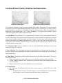
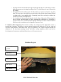
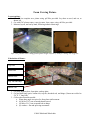
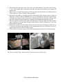
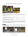
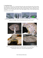
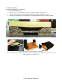
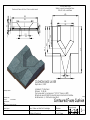
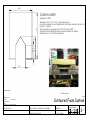
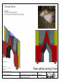
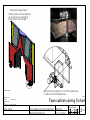
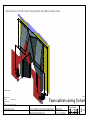
Whirlwind Wheelchair International’s Contoured Pressure Relief Cushion a guide to building a carved foam cushion for adults (a fitting guide is available from Whirlwind Wheelchair) Video guide: whirlwindwhelchair.com/cushion Carved foam base layer only ©2009 Whirlwind Wheelchair Assembled cushion Overview This guide explains how to carve a foam pressure relief cushion following the design of Jamie Noon, designed in conjunction with Whirlwind Wheelchair. This is a four layer cushion that has a soft layer, a contoured base layer, and two optional sub layers to add additional relief. This guide also shows how to select which foams to use for the top layer and base layer, and also how to perform a test to ensure that the foam is the right density. This cushion is designed to relieve seating pressure for wheelchair riders who have limited sensation in their legs and buttocks. It helps relieve a rider’s weight on bony areas which are vulnerable to pressure sores which can be very dangerous to a rider. Using this cushion does not eliminate the need for the rider to reposition their weight frequently, nor to perform proper self-care, nor does it guarantee against the development of pressure sores. See the Whirlwind publication, “RoughRider User Manual”, for more information on pressure. While it isn’t necessary to make a carving fixture to fabricate these carved foam cushions, a fixture ensures quick and accurate cuts, and it may be worthwhile for the manufacture of more than a few cushions. These cushions are designed for easy replacement of the softer top foam (not carved), but when the bottom foam requires replacement as well, it can be carved by hand if a fixture is not available. Top foam typically lasts for 3 months while bottom foam typically lasts for 6-9 months. Whirlwind provides drawings and instructions for making a carving fixture to quickly and easily carve the cushion base. The carving fixture can be made from sheet metal. After building the fixture, make sample cushions and check the dimensions to ensure that they are within tolerance. Please contact Whirlwind for additional technical support. All dimensions are in millimeters. This cut pattern optimizes the use of sheet metal. Sheet should be 12 gauge / 2mm thick steel. Variations These cushions can also be carved by hand, by drawing the cut lines onto the cushion with a felt marker, and free-hand cutting along those lines. The fixture described in this guide allows the cushions to be carved quickly and accurately, but for replacement or small batches, the cushions can be carved by hand with good results. Some base foams like “Ethafoam” may be suitable even though they do not have the same compression characteristics. Contact Whirlwind for more information on alternate foams. This document builds on the work by the Motivation Charitable Trust, published in 2001 in the document A Guide to Understanding and Making Pressure Relieving Cushions. ©2009 Whirlwind Wheelchair Contoured Foam Cushion Features and Explanation Firm foam cushion base Cushion base with top foam layer This cushion is designed to reduce pressures common at the Ischial Tuberosities (ITs) and to relocate the pressure load to the proximal thighs (middle of upper leg close to the pelvis). In most cases the proximal thighs are an ideal area for loading in order to relieve pressure at bony areas which are at higher risk of skin damage such as IT's, Greater Trochanters (GT's), and Coccyx (tailbone). In this cushion the highest point is under the proximal thigh. A. Ischial Relief: For an adult, the IT's are approximately 1.5 inches (38 mm) lower than the bottom of the GT's when sitting. The ischial recess has an open back in order to promote air and blood circulation and to allow drainage of liquid toward the rear of the cushion. The firm foam (often chip foam) at the bottom of the ischial relief should be no thinner than .5 inch (13 mm). If the top foam available is very soft, a thicker layer under the ischial releif may be needed to prevent "bottoming out", when the ITs sit with firm pressure on the cutout. B. Trochanteric Shelf: This level platform at each side of the Ischial Relief will help to transfer load bearing from the IT's to the GT's. C. Pre-Ischial Bar: This is the highest point on the cushion and acts as a fulcrum under the femurs. As the knees are lowered (by adjusting the footrests), some pressure is moved from the GT's forward onto the proximal thighs. D. Thigh Relief: The thickness of the cushion becomes less at the front of the cushion. This serves three main functions. Helps to maintain a low cushion thickness for easier transfers in and out of the wheelchair. Creates a natural Abductor (knee separator) to prevent the knees from coming together and increases stability. Helps to focus pressure at the Pre-Ischial Bar by lowering the knees. E. Perineal Relief: The front edge of the Ischial Relief (the back cutout) comes to a point. This serves four functions. o The added space in front of the pelvis helps to prevent impingement of male anatomy and can improve ease of catheterization and other urinary care processes. ©2009 Whirlwind Wheelchair o The shape of this relief matches the angle of the left and right IT’s. This helps to reduce high point pressure at the sharp front edge of the IT’s when the pelvis moves forward in the cushion. o The pointed front also allows space for the urethra as it passes in front of the pubic bone. The extra space here helps to prevent closing of the urethra when leaning forward or sitting with a very upright pelvis. Promoting urine flow can help to reduce the incidence of Urinary Tract Infections. o Air circulation is increased by having this relief in front of the pelvis. When the pelvis moves forward and backward (as when propelling the wheelchair or performing a pressure relief), air is circulated under the pelvis. This helps to reduce moisture and heat which are major contributors to development of pressure sores. F. Abductor (Knee Separator): The contour created by the cutting out of the thigh reliefs creates a natural knee separator. This helps to prevent internal rotation and adduction of the hip joint and increases sitting stability. Wheelchairs with sling seat upholstery can promote internal rotation and adduction of the hip joints (rotating inward and knees coming together), which can lead to development of contractures and joint deformities, as well as pressure sores. Cushion Layers Cushion Cover not pictured Top Layer Base Layer Sub Layer 1 Sub Layer 2 ©2009 Whirlwind Wheelchair Foam Carving Fixture Layout options: 1. Print full size template on a plotter using .pdf files provided. Lay sheet on steel, and cut, as shown left. 2. Cut with CNC plasma cutter, water jet cutter, laser cutter, using .dxf files provided. 3. Measure, layout, and cut by hand, following technical drawings. Left: CNC plasma cutter cutting fixture plates. Right: Layout by hand for cutting with a jig saw. Fabrication of fixture: Top Plate Front Plate Bottom Plate Top Tab and Hinge Carving Fixture with cushion base layer Bottom Tab 1. Cut parts: Bottom plate, front plate, and top plate. 2. Cut and drill hinge parts: bottom tab, top tab, threaded rod, and hinge (10mm nut welded to 5/6” X 1” long bolt) 3. Collect other materials needed: a. 50mm long angle iron piece for front plate reinforcement b. (8) M10 or 3/8” nuts to match threads on rod c. (4) M8 or 5/16” nuts to match bolt on hinge d. (6) washers—flat and split-ring assortment ©2009 Whirlwind Wheelchair 4. Weld bottom tab onto bottom plate. The center of the hole should be 15mm from the back edge of the of the bottom plate, and 60mm from the side edge of the bottom plate. Repeat on opposite side. 5. Weld one face of an M10 nut to the top of the head of the M8 bolt. Drill out the M10 threads to 10mm. Make two. This is called the “hinge assembly.” 6. Assemble the threaded rod through the holes in the bottom tabs with two nuts to clamp on either side of the tab. Slide the drilled M10 nut over the threaded rod, with the M8 bolts facing outwards away from the center of the fixture. Slide the angle tab over the holes, with the outer edge of the angle facing the threaded rod. Assemble with washers on both sides of the tab. 7. Place the top plate onto the bottom plate and align edges. Clamp the angle tab to the top plate where it intersects to set the hinge location. Ensure that the fixture is symmetrical. Tack weld the top tab to the top plate. 8. Remove the top plate, and reassemble with one nut on each side of the hinge assembly nut, at 2”, 50mm, or whatever the dimension of the cushion foam, but lower by 2mm to allow for slight compression of the foam to hold it in place. 9. Test the fixture by carving a foam cushion and comparing dimensions to the cushion drawings. Left: Hinge Assembly. Right: Reinforcement between front plate and base plate ©2009 Whirlwind Wheelchair Creating a pressure relief cushion—carved foam Material Selection Base layer Top Foam Sub layer Base layer: Use firm chip foam.. In this case, a 2” x 2” x 2” block of foam is compressed to 1” high, requiring between 10 and 18 pounds force. We have found foam that works well with compression of 18 lbs. (4.5 to 8.2 kg) The top foam should be 2” thick, and a 2” x 2” x 2” block should compress to 2” x 2” x 1” high with at least 5 pounds force. (5-9 lb range, or 2.3 to 4 kg) The sub-layer sheets should be 3/8” / 10mm, or ½” / 12 mm thick chip foam. Often this foam is used under carpets and has a backing to hold it together. Cushion Cover: The cushion cover should have two types of material. The sides and bottom should be durable nylon, and the top should be a stretchy and soft fabric. Use a zipper or hook and loop material (i.e. Velcro) to hold the cushion cover closed. The closure should not be in contact with the user when sitting on the cushion (it could cause a pressure sore). Foam Testing To select appropriate foam for each layer, test samples of the chip foam and soft top foam to ensure correct density. Compress a 2” X 2” X 2” sample of foam to half its height, and measure the force required for this compression. Foam tester: Measure the force required to compress a 2” X 2” X 2” cube of foam to 1” thick. Left: Tester components. Right: Foam tester assembled. ©2009 Whirlwind Wheelchair Tube end sharpened as foam cutter Foam to be tested (cut to 50 mm cube and hole cut through) 50X50 mm flat plate with hole Spring Scale (up to 10 kg) "T" plate (50X50 mm with hole and 40 mm Marks to indicate 0 and 25 mm compression Rod with hole at each end Units conversion: Ok to interchange 25mm with 1” 50mm with 2” 1 kg with 2.2 lbs Guidelines for foam firmness: Firm foam for base layer and contours 4.5 to 8.2 kg Seat and backrest surface foam 2.3 to 4 kg Lateral trunk support foam 5 to 10 kg Headrest base (contour) foam 5 to 10 kg. Headrest surface foam 3 to 4.5 kg Strap pads 2.5 to 5 kg Elbow pad (for tray surface) 5 to 10 kg Note: Some foams cannot be compressed (i.e. ethefoam) Foam Firmness Tester Description: Can be made with basic materials and technology. Foam firmness can be quantified in kilograms required to compress 50 square mm of any foam by 50 % (25 mm). To be used to quantify foam firmness between suppliers and users of foam for seating and cushions. Metric Parts: •Spring scale •"T" plate •Flat plate •Rod •"S" pin •Foam cube 50mm on each side Retaining "S" pin (or the 50 mm plate can also be welded here, perpendicular to the rod) Date Modified: Oct 7, 2009 Materials: •Metal plate •Brazing/welding •Epoxy if no welding •6mm rod •tube with 8mm inside diameter •Wire for "S" pin •Scale (up to 10 kg) Method: •Cut a foam sample 50X50X50 mm (use flat plate as cutting guide). Use no glue. •Cut hole in foam using "T" plate tube. •Feed rod through and hook scale on. •Pull "T" plate down until 1" mark shows. •Read number on scale. Far Left: Making a hole for testing the foam. Left: Test setup: Pull downward on the spring scale until the 2” thick block of foam has compressed to 1”, and read force required at this compression. ©2009 Whirlwind Wheelchair Making the Cushion 1. Base layer Cut the base layer from chip foam, to the correct dimensions for the size cushion that is required. A cutting fixture with two slots for a knife blade works well to ensure straight, even cuts. All cushions are 420mm deep, and the five widths are 320, 355, 400, 440, and 480mm. Cut foam with a slotted Fixture to ensure straight cuts 2. Centering: Mark the center of foam (from left to right). 3. Locating Base Layer in Fixture: Lay the foam in the carving fixture, with the back of the foam at the end with the hinges. The lid should compress the foam about 2mm when it is lowered. The foam should be centered on the fixture, for any size cushion. Base layer in Carving Fixture. Left: Before cutting, Right, after cutting. ©2009 Whirlwind Wheelchair 4. Carve Base Layer Carve along each edge of the fixture. It works well to cut from the back of the back cutout along the sides towards the center, from each side, and each of the cuts for the bottom of the thighs from the outer edge of that cut. Use an electric carving knife or serrated breadknife to make these cuts. (A hacksaw blade with the side edges of the teeth filed off works well for short cuts, and to make small adjustments at the fitting of the wheelchair. Hacksaw blades are inexpensive and common, and their flexibility allows them to create curved cuts.) Top Photos: Cutting Thigh Relief Bottom: Cutting IT relief cutout ©2009 Whirlwind Wheelchair 5. Ischial Relief Foam Cut a thin layer of foam (1/2” or 12mm thick) from the wedge removed from the back of the cushion. Glue this thin piece into the foam base using a Contact Cement such as Shoe Glue. Apply glue to each edge (cushion base and foam wedge) and let dry before pressing together. This part will provide some cushioning as well as hold the two sides of the foam together so they do not spread apart when someone sits on the cushion. Ischial Relief Foam. Use the foam wedge removed from the foam base cutting. Cut off a ½” / 12mm thick layer, and glue it in place at the bottom of the IT cutout, as shown. Top: Cut ½” thick foam from the bottom of the wedge that was cut out from the rear cutout. Bottom Left: Glue in place with contact cement, pressing edges firmly. Bottom Right: The base layer with foam cutout glued in place ©2009 Whirlwind Wheelchair 6. Top Layer: Cut the top layer of the cushion from foam that is somewhat softer than the base foam to the same dimensions as the base layer. Cutting top foam with a straight edge cutting fixture 7. Sub layers: Cut two sub-layers from thin chip foam. These layers provide additional pressure relief for some wheelchair riders, and will be selected at the time of the wheelchair fitting. These layers should have a cutout to match the bottom of the IT cutout, as shown in the drawings. Left: Bottom of sub-layer with plastic backing and mesh. Right: This foam can be cut with scissors. ©2009 Whirlwind Wheelchair 8. Cushion Cover: Make a cushion cover with a hook and loop or zipper closure in the rear, using durable fabric for the bottom and sides, and stretchy, soft, non-rotting fabric for the top. Most fabrics are not stretchy enough to use without pleats; if your fabric does not stretch easily, sew the cover with space for the sitting bones by sewing in several pleats along the back edge of the cushion cover. The back of the cushion fabric should be 4” wider than the width of the cushion. There should be four pleats that take up 1” of fabric each, along the back of the cushion cover. Left: fingers should sink easily into the foam, through the cushion cover. Center: Small pleats. Right: cushion top fabric sketch ©2009 Whirlwind Wheelchair 9. Cushion Assembly: Assemble the cushion layers as follows: The softer foam is on top. The base layer is underneath the soft foam, wrapped in plastic for protection. The two sub layers are on the bottom with the cutouts aligned with the base layer. Put these layers into the cover so that the cover opening ends up at the rear of the cushion. 4 layer cushion assembled without cover Left: Cushion in cover (with sub layers removed) Center: Wrap base layer in plastic before assembly, leaving enough plastic to fill the IT relief cutout Right: One style of cushion cover ©2009 Whirlwind Wheelchair Cushion Drawings Cushion Base Layer Widths to match wheelchair Sizes: 355, 400, 440, and 480mm Back end View--with two 10 mm cutout inserts 400 400 255 153 10 38 400 10 71 51 255 419 267 241 200 123 119 153 20 159 CUSHION BASE LAYER September 1, 2009 Material:= 2" chip foam Firmness: 10-18 Lbs (Force required to compress a 2" X 2" X 2" Cube by 50%) All features are left/Right Symmetrical and centered on midline. All dimensions +/- 3mm unless specified. Assembly Number: Assembly Title: Version: Contoured Foam Cushion on 10/6/2009 Approval Date: Drawing Set Last Saved On: 10/6/2009 Sheet Title: Drawn By: Dimensions in: Base Layer Aaron Wieler and Matt McCambridge Millimeters Project Title: Assembly Issued By & ©: Optimized for: Whirlwind Wheelchair 8½" x 11" Paper Projection: First Angle (European) Sheet No. 1 of 3 200 200 118 123 177 Side view. Glue this piece into the Base Layer with contact cement 119 Cushoin cutout filler is cut from the foam that is removed during Base layer cutting 13 153 Assembly Number: Assembly Assembly Title: Version: Contoured Foam Cushion on 10/6/2009 Approval Date: Drawing Set Last Saved On: 10/6/2009 Sheet Title: Drawn By: Dimensions in: Cushion bottom wedge Aaron Wieler and Matt McCambridge Millimeters Project Title: Issued By & ©: Optimized for: Whirlwind Wheelchair 8½" x 11" Paper Projection: First Angle (European) Sheet No. 2 of 3 356 CUSHION INSERT Material:= 3/8" to 1/2" (10 to 12 mm) dense foam or similar compliant, non-rotting materal (Chip Foam, Insulation Foam, etc) Firmness: 10-30 Lbs (Force required to compress a 2" X 2" X 2" Cube by 50%) All features are left/Right Symmetrical and centered on midline. All dimensions +/- 3mm unless specified. 201 125 419 September 1 2009 153 Assembly Number: Cushion Layers Assembly Assembly Title: Version: Contoured Foam Cushion on 10/6/2009 Approval Date: Drawing Set Last Saved On: 10/6/2009 Sheet Title: Drawn By: Dimensions in: Cushion Insert Aaron Wieler and Matt McCambridge Millimeters Project Title: Issued By & ©: Optimized for: Whirlwind Wheelchair 8½" x 11" Paper Projection: First Angle (European) Sheet No. 3 of 3 Carving Fixture Drawings Carving Fixture Material: 2 to 4mm thick steel sheet Nuts, bolts, assorted steel stock for hinge Assembly Number: Assembly Assembly Title: Version: Foam cushion carving fixture on 9/11/2009 Approval Date: Drawing Set Last Saved On: 9/11/2009 Dimensions in: Sheet Title: Drawn By: Project Title: Millimeters Aaron Wieler, Matt McCambridge Optimized for: Carving Fixture Asy Issued By & ©: Whirlwind Wheelchair 8½" x 11" Paper Projection: First Angle (European) Sheet No. 1 of 4 Adjustable Hinge Detail The top plate can be adjusted up and down by changing the position of the hinge A Assembly Number: A bolt head is welded to a nut that is drilled out to slide over the threaded rod. Assembly Title: Version: Foam cushion carving fixture on 9/11/2009 Approval Date: Drawing Set Last Saved On: 9/11/2009 Dimensions in: Sheet Title: Drawn By: Project Title: Millimeters Aaron Wieler, Matt McCambridge Optimized for: Hinge detail Assembly Issued By & ©: Whirlwind Wheelchair 8½" x 11" Paper Projection: First Angle (European) Sheet No. 2 of 4 Exploded View of Foam Cushion Carving Fixture with 400 mm wide cushion Assembly Number: Assembly Assembly Title: Version: Foam cushion carving fixture on 9/11/2009 Approval Date: Drawing Set Last Saved On: 9/11/2009 Dimensions in: Sheet Title: Drawn By: Project Title: Millimeters Aaron Wieler, Matt McCambridge Optimized for: Exploded View Issued By & ©: Whirlwind Wheelchair 8½" x 11" Paper Projection: First Angle (European) Sheet No. 3 of 4 506 10 280 145 220 180 122 425 425 173 122 260 506 253 Bottom plate dimensions Top plate dimensions 13 159 20 506 Front plate dimensions Suggested Layout and cutting process: CNC Plasma cutter, parts nested on a sheet Assembly Number: Assembly Assembly Title: Version: Foam cushion carving fixture on 9/11/2009 Approval Date: Drawing Set Last Saved On: 9/11/2009 Dimensions in: Sheet Title: Drawn By: Project Title: Millimeters Aaron Wieler, Matt McCambridge Optimized for: Dimensions Issued By & ©: Whirlwind Wheelchair 8½" x 11" Paper Projection: First Angle (European) Sheet No. 4 of 4 Carving Fixture Layout and Dimensions Base Plate Top Plate Front Plate ©2009 Whirlwind Wheelchair