1
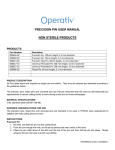
Surgical Technique
Version 2.1
AchieveCAS™ Knee Surgical Technique
Contents
AchieveCAS Knee Surgical Technique ..................................................2
General Precautions ..............................................................................3
Operating Room Setup ..........................................................................4
Start Up ..................................................................................................5
Surgical Plan............................................................................................6
Operative Side ........................................................................................8
Instrument Calibration ............................................................................8
Reference Array Placement ....................................................................9
Touch-Less Navigation............................................................................11
Anatomic Registration ............................................................................12
Pre-Op Limb Alignment ..........................................................................16
Femoral Sizing ........................................................................................17
Cut Navigation ........................................................................................18
Navigation – Femoral Cut........................................................................18
Navigation - Femoral Measure................................................................20
Navigation – Femoral Guide....................................................................21
Navigation – Tibial Cut ..........................................................................22
Navigation – Tibial Measure ..................................................................23
Post-Op Limb Alignment ........................................................................24
Ligament Balancing ................................................................................25
Archive Surgery Data ..............................................................................26
Actions Button Menu ..............................................................................27
Nota Bene
The technique description herein is made available to the healthcare professional to illustrate the author’s
suggested treatment for the uncomplicated procedure. In the final analysis, the preferred treatment is that
which addresses the needs of the specific patient.
1
AchieveCAS™ Knee Surgical Technique
Smith & Nephew is proud to announce the
launch of Version 2.1 of the AchieveCAS
system for knee arthroplasty. This surgical
technique will guide you through the software
and instrument workflow for an AchieveCAS
knee arthroplasty.
The AchieveCAS system offers the surgeon
accurate, real-time, imageless computer
navigation and facilitates precise knee
implant placement.
The software interface and workflow of the
AchieveCAS system is designed to be
streamlined and user-friendly. The advantage
is that the surgeon only sees the numerical
values and images that he or she needs –
no extraneous information that distract rather
than help.
The AchieveCAS system also enhances the
use of MIS techniques. The increased “vision”
from the AchieveCAS system advances and
strengthens minimally invasive surgery.
All told, the AchieveCAS system is compact,
simple and inexpensive. A simply brilliant
concept. Turn it on.
2
General Precautions
The AchieveCAS™ system should only be used by
trained surgeons.
Do not proceed any further in the surgery if there are
any doubts regarding the quality of the registration
(i.e., orientation of a femoral/tibial array has been
compromised or the AchieveCAS system is making
recommendations that the surgeon strongly feels do
not seem accurate). If this occurs, the registration
process should be restarted or the surgeon can refer
to traditional TKA technique as described in stated
technique guide.
The AchieveCAS system should only be used with
the instruments provided by Smith & Nephew for the
specific application.
Before every surgery, verify that the navigation
instruments are not damaged and in good condition
to perform the surgery.
Strong infrared sources within the vicinity of the
arrays may affect the infrared camera's ability to
track the navigational array. There is a very small
percentage of OR lights that may cause this. If you
feel that your OR could be in this group, try briefly
averting the OR lights from the surgical field.
3
Operating Room Setup
Appropriate positioning of the optical tracking
equipment (camera and arrays) is vital to ensure
an unobstructed camera view of the surgical field.
Care must be taken to ensure that no operating
room equipment obstructs the field between the
camera and the navigation instruments.
The AchieveCAS™ system should be stationed in
the OR with a minimum distance of approximately
4 feet maintained between the camera and the
calibration/navigation areas.
The OR setup must be determined according
to the side of the operated knee (left or
right knee), the specifications of the optical
system and the standard instrument setup.
Camera
Camera
view
Operative
side
Due to the orientation of the arrays, the camera
is typically placed approximately 30° medially
to the patient's feet. The exact camera position
depends on the OR setup, the surgeon's
preferences and the position of the tracked
instruments on the patient.
Note: Line of sight is essential to the proper use
of the optical tracking system. However, line of site
only needs to be maintained while the surgeon
is actively using the system (i.e., registration,
navigating cutting blocks, verifying cuts, ligament
balancing, etc.).
4
Surgeon
Start Up
Turn the AchieveCAS™ unit on via the power toggle
switch on the back of the computer. Press the
Knee icon button on the touch screen to begin
the AchieveCAS operation.
Select a surgeon profile from the list provided or
press the Create button to create a new surgeon
profile (see next screens).
Type in a name for the new profile.
5
Surgical Plan
Select the appropriate implant for the profile.
Select the desired Femur settings.
Notes: The software defaults to a femoral implant
position of 4° Flexion relative to the mechanical
axis. Since most femurs have an anterior bow, the
anatomic axis of a typical distal femur is flexed
approximately 4° to the mechanical axis. The
surgeon may change the target Flexion value for
individual patients who may have more or less
distal femur flexion relative to the mechanical axis.
The software defaults to a femoral implant position
of 0° Varus. It is important to note that this
measurement is relative to the mechanical axis of
the femur. With standard instrumentation, the
Valgus angle (typically 5° or 6° Valgus) is relative to
the anatomic axis. If desired, the surgeon may
change the target Varus value for individual
patients.
Select the desired Tibia settings.
6
Select the desired General settings.
Notes:
Joint Line Indexing
If “Yes” is selected for Joint Line Indexing, the computer will modify
the target resection depths for the distal femur and proximal tibia cuts
based on the amount of wear on the medial or lateral side of the joint.
The goal of Joint Line Indexing is to ensure a precise extension gap
and maintain the position of the joint line.
Note that for navigation of the JOURNEY™ implant, Joint Line Indexing
is automatically selected.
If “No” is selected for Joint Line Indexing, the computer will select the
healthy condyle or plateau with respect to the mechanical axis and
recommend the standard resection.
Check Points Acquisition
This feature allows the surgeon to register additional landmark points
at the completion of the registration. Using the pointer, the surgeon will
register a random point (marked by bovie) on the tibia and one point on
the femur, as prompted by the computer. If at any time during the
procedure the surgeon feels an array has moved and the accuracy of
the registration is compromised, they are able to access this screen to
verify. To access this screen intra-operatively, press:
Actions
Verify Checkpoints
Sequence
The Sequence feature allows the user to specify the order of the cutting
sequence as it appears in the software flow. In the Sequence field,
“Fem” represents the Distal Femur cut.
GENESIS™ II Measurement Tool
When a GENESIS II or GENESIS II SPC implant is chosen, the user must
specify which version of the Measurement Tool will be used. This is only
for the purpose of manual calibration, which is not required unless the
measurement instrument is damaged.
Measurements
The angular and linear measurement settings determine when the
computer will display a solid green line during navigating values,
indicating a desirable resection. If measurements are set at 1,
displayed values will turn green when navigated instruments are
within 1° or millimeter of the desired target.
7
Operative Side and Instrument Calibration
Select the operative side.
Calibrate the Pointer Probe by inserting its tip at a 90° angle into the
square divot on either the Femoral or Tibial Reference Array. Make
sure the pointer and array are not too close to the camera. Verify that
the Pointer tip is seated in the bottom of the divot, and that both the
Pointer and the appropriate Reference Array are visible to the camera.
When the calibration is complete, a beep will sound.
Make sure that no other arrays or spheres are visible to the camera
during calibration. This step is best performed while holding the chosen
array parallel with the floor with one hand and the Pointer Probe in
the other.
8
Reference Array Placement
The two-pin fixator is designed to accommodate
any combination of two 3mm or 4mm pins (ie, two
3mm, one 3mm and one 4mm, or two 4mm).
Place two partially threaded pins into the distal femur
using the AchieveCAS™ Drill Guide, making sure
that the pins will not interfere with any bone cuts or
the femoral trial.
Slide the fixator over the pins until it is approximately
one inch above the skin. It is important that the
large black knob is loosened all the way and the site
for array attachment is facing upwards and away
from the incision.
The large knob should be tightened firmly to lock the
fixator against the pins, using the spanner wrench
from the set if necessary.
9
Reference Array Placement continued
Place the magnetic portion of the femoral reference
array onto the fixator, and adjust to the desired
position. The black dial on the underside of the
fixator will allow for rotational adjustments, while
the dial on the side of the reference array will allow
for flexion and extension of the array.
Once the array is in the desired position, tighten
both dials securely by hand to prevent movement
of the array during the procedure.
Repeat the above procedure to attach the tibial
reference array to the proximal tibia, making
sure that the proximal pin is at least a hand's
breadth beneath the top of the proximal tibia.
Notes: Although the arrays may be removed
and replaced on the magnetic connections,
the fixators and adjustable joints must remain
fixed throughout the procedure.
Be aware of the risk of causing damage to
the saphenous artery or femoral artery and
vein while inserting the pins.
Be aware that muscle fibers may apply bending
forces on the pins.
Always ensure that reflective spheres are
firmly seated.
Always minimize handling of the spheres, since
accuracy is optimized by uniform reflection off
the surface of unblemished spheres.
10
Ensure that both the Tibial and Femoral reference arrays can be seen
by the camera with the leg in both deep flexion and extension. To
access this screen intra-operatively, press:
Actions
Aim Camera
If at any time an array cannot be seen by the camera, a shaded circle
will appear behind the array's representative icon at the bottom of the
applicable screen.
Can be seen by camera
Cannot be seen by camera
Touchless Navigation
Navigating through the application can also be controlled from the
sterile field by using the touchless commands. There are three divots
on the Femoral and Tibial Reference Arrays, with a corresponding
shape (circle, square, and triangle). These shapes correspond to
certain commands in the AchieveCAS™ software, as depicted by the
corresponding images on the screen.
The tip of the Pointer Probe may be placed into the corresponding
divot to trigger the action associated with the button. Visual and
audible feedback will notify the user the action has been executed.
11
Anatomic Registration
The center of the femoral head is calculated by
recording 14 static positions of the Femoral
Reference Array. The 14 points should be taken
with the femur in a conical pattern relative to the
pelvis, holding the leg steady for each point until
a “beep” is heard.
The pelvis and the optical camera must remain
immobile during registration of the 14 points to
locate the femoral head center.
The contraindications for femoral head detection
are joint pathologies including severe hip arthritis
and hip dysplasia.
Note: On every page where there is a list of points
to acquire, two buttons become available when at
least one point is digitized: Clear All and Clear Last.
The last acquired point may be deleted by pressing
Clear Last, which is also activated touchlessly by
the circle divot. Pressing Clear All deletes all points
acquired on the page.
12
Hold the Pointer Probe tip steady on the most
prominent point of the medial malleolus. Ensure
that the leg positioner, if used, does not prevent
accurate digitization of the point.
The reading of the point is triggered automatically
based on a stability criterion. After each point is
successfully acquired, a “beep” will sound.
Follow the same process to digitize the most
prominent point of the lateral malleolus.
Hold the Pointer Probe tip steady on the medial distal
condyle to take the first distal condyle point. In the
bottom right corner of the screen, the software prompts
the user to take a number of points on the medial
distal femoral condyle, as specified in the surgical plan.
The surgeon should acquire the specified number
of points at the most distal area of the condyle with
small variations of anterior-posterior position. The
software will then choose which of the points is the
most distal to calculate depth of resection.
As the surgeon begins to take points, the number
in the bottom right corner of the screen counts
down until the medial distal condyle point acquisition
is complete. Once complete, the software will beep
twice and proceed to the next step.
Hold the Pointer Probe tip steady on the distal
mechanical axis, which is in the trochlear groove
approximately where the surgeon would drill to
access the intramedullary canal.
The same process should be followed for the
digitization of the lateral distal condyle.
13
Anatomic Registration continued
Hold the Pointer Probe tip steady on the most
posterior point of the medial femoral condyle. It
is recommended to flex the knee approximately
115° to allow for accurate digitization of
the posterior condyle.
Follow the same process to digitize the most
posterior point on the lateral femoral condyle.
Optional
If the A/P axis was selected as the femoral axis of
rotation, the user will be prompted to digitize the
anterior and posterior trochlear groove. It is
recommended that the surgeon draw the A/P
axis onto the femur before taking the trochlear
groove points to ensure accuracy.
If the epicondylar axis was selected as the femoral
axis of rotation, the user will be prompted to put
the Pointer tip on the medial epicondyle, and then
the lateral epicondyle.
14
Hold the Pointer Probe tip steady on each of two
points on the anterior cortex.
The two points should bracket the point where
the sizing stylus from the standard instrumentation
would touch the anterior cortex, as shown on
the screen. One point should be acquired more
distally and the other point more proximally; the
order is not important, but the two points should
be approximately 2cm apart.
If the Anterior Cortex points are digitized on the
prominent lateral ridge of the femur, the resulting
anterior cut will typically be less aggressive than
if the points are digitized in the low point in the
center of the anterior cortex.
Hold the Pointer Probe tip steady on the medial
plateau at the place where the resection level should
be calculated. The software will again prompt the
user to take a specified number of points in the
lowest area of the medial plateau.
Hold the Pointer tip steady on the proximal
mechanical axis entry point, which is
approximately where the surgeon would
drill to access the intramedullary canal.
Follow the same process to digitize the
lateral plateau.
Flex the knee to 90° (± 2°) and hold it steady with
the tibia in a natural, unstressed rotational position.
The knee must remain steady to trigger the projection
of the femoral mechanical axis on the tibial plateau.
The value will turn green when the knee is in the
correct range.
Optional, depending on surgical plan
Option 1
Hold the Pointer Probe tip steady on the medial third
of the tubercle.
Option 2
Hold the Pointer Probe tip steady on the ACL footprint
and then on the PCL footprint, as directed by the
screen instructions.
15
Pre-Op Limb Alignment
When registration is complete, the computer will display the
preoperative alignment of the Mechanical Axis. The surgeon can use
this screen to measure preoperative varus or valgus deformity, range
of motion and flexion contracture.
The Evaluate Limb Alignment screen may be accessed at any time
once registration is complete by pressing:
Actions
16
Eval Limb Alignment
Femoral Sizing
The AchieveCAS™ system computes the femoral component size based on the implant referencing method
and the anterior-posterior dimension of the digitized femoral bony landmarks. The system uses the target
values entered in the Input Surgical Plan screen, such as the femur flexion angle, to compute the size.
Flexion may be changed on this screen and will be automatically updated in the Surgical Plan.
Posterior Implant Referencing
Posterior display is 0.0mm; anterior display will read “Large” if the implant's A/P dimension is larger than
the digitized anatomic A/P dimension (this indicates possible anterior overhang), and will read “Small” if
the implant's A/P dimension is smaller than the digitized anatomic A/P dimension (this indicates a
potential for notching).
Anterior Implant Referencing
Anterior display is 0.0mm; posterior display will read “Small” if the implant's A/P dimension is smaller than
the digitized anatomic A/P dimension (this indicates possible additional posterior resection), and will
read “Large” if the implant's A/P dimension is larger than the digitized anatomic A/P dimension (this
indicates a potential for stuffing the flexion gap).
Notes: The software will always round up to the next size with Posterior Referencing and will always
round down with Anterior Referencing. It is recommended to view the size fit with both Anterior and
Posterior Referencing (ie, both larger and smaller implants) before choosing the appropriate size. The user
can toggle between anterior and posterior implant referencing by pressing the appropriate screen button.
The implant size can also be changed either touchlessly or by using the + and - boxes to select the most
appropriate size. In case of any doubt regarding the femoral component sizing, confirm the sizing with the
standard sizing instruments.
On the lateral femur representation, the yellow dots represent the location of the implant's anterior flange
point and the implant's most posterior condyle. The green dots represent the digitized anterior cortex points.
By implant design, the default size for the PROFIX™ femoral component is 2.5mm smaller than the size of
the digitized femoral A/P dimension.
The array recognition feature may be used to customize the order of the navigation screens.
Starting at the Select Femoral Size screen, place the Pointer Probe tip inside the cutting guide
array that corresponds to the desired navigation screen. The AchieveCAS system will recognize
this as an indication to move to the corresponding screen.
17
Cut Navigation
All navigation screens make use of target lines and target values to guide
navigation. When the navigated instrument is exactly on target, the
navigated line becomes thick and green. The box in which values are
displayed also becomes green. When the value is on target, it matches
the target that is displayed in green text underneath the value box.
To align a navigated block, first align the varus and flexion angles using
visual cues. When an angle is in the target range defined in the Surgical
Plan, the navigated line and the applicable field become green.
When both angles are in range, depth can be aligned. When depth is in
the target range, the navigated line will become solid instead of dashed.
Note: Do not use the pictorial representation of the bones for
component positioning purposes. They are provided solely to visualize
axis orientation and do not represent the actual bony anatomy.
Navigation - Femoral Cut
The appropriate distal cutting block should be attached to the GENESIS™ II
Valgus Alignment Guide and set to the appropriate resection depth.
Attach the distal cutting block array to the distal cutting block. Place
the distal cutting block assembly onto the distal femur, and use the
navigation screen to guide the block into the desired cut position.
Using a pin driver, hold the flexion angle steady at the desired target
value and drive the first trocar pin though the distal cutting block into
the bone. This will set the flexion angle and resection depth.
With the Flexion angle secured by the first pin, rotate the assembly until
the Valgus angle is at its desired target, and place a second trocar pin
parallel to the first.
If a change in depth is desired, the block can be lifted and reset to the
desired resection depth.
Place a third trocar pin while holding the assembly to the desired
parameters. Remove the valgus alignment guide (if attached). Remove
all arrays to protect them from fluid and debris while cutting.
Perform the distal femoral cut as usual.
Note: The left and right distal cutting blocks are interchangeable.
The contraindicated block may be used to prevent tracking issues,
if necessary.
18
Navigation - Femoral Cut
19
Navigation - Femoral Measure
After making the distal cut, place the Measurement
Tool on the cut. Ensure that the instrument's surface
is flat against the distal cut.
If the measured cut is not within acceptable
parameters, the surgeon may use the saw or a
file to revise the cut as appropriate. Repeat the
Measure step after revising the cut.
20
Navigation - Femoral Guide
Position the Measurement Tool (GENESIS™ II or
JOURNEY™ knees) or the 4-in-1 cutting block with the
appropriate array attached (PROFIX™ system) against
the distal cut. First, adjust the rotation of the block,
then adjust the A/P position.
Posterior Offset (in millimeters) is the distance
between the location of the posterior condyle of
the implant and the digitized posterior condyle.
A negative Posterior Offset indicates additional
posterior resection, while a positive value indicates a
risk of inadequate posterior resection (overstuffing).
Anterior Flange Overhang (in millimeters) is the
distance between the location of the implant anterior
flange point and the digitized anterior cortex line.
A negative Flange Overhang indicates a risk of
notching, while a positive value indicates a smaller
anterior resection.
If the current size does not allow for appropriate
Posterior Offset and Flange Overhang values, select
a different femoral implant size in the Size field at
the top of the screen.
For GENESIS II or JOURNEY implants, use the
Measurement Tool to drill both holes. Remove the
tool and put the corresponding AP cutting guide in
the holes. Perform the cuts according to the standard
GENESIS II or JOURNEY surgical technique.
For the PROFIX system, when the navigated 4-in-1
cutting block is in position, pin it to the bone. Remove
the array and perform the cuts according to the
standard PROFIX implant surgical technique.
Rotation indicator (in degrees) is the angle between
the axis of the femoral component and the
referenced rotational axis chosen in the Input
Surgical Plan screen.
By design, the GENESIS II femoral component has
3° of external rotation built into the articular
geometry, with respect to the 4-in-1 cuts. The
rotation displayed by the software is the rotational
position of the 4-in-1 cuts.
By design, the default Posterior Offset for the PROFIX
femoral component is -2.5mm, in accordance with
the default implant sizing of 2.5mm smaller than the
digitized femoral A/P dimension.
Note: Sizes 1 & 2 for the JOURNEY system cannot
be navigated.
21
Navigation - Tibial Cut
For enhanced stability, attach the appropriate Tibia
Cutting Block to the GENESIS™ II or JOURNEY™ EM
Alignment Guide (use a non-spiked rod).
Position the EM Alignment Guide and cutting block
onto the anatomy as directed by the standard
surgical technique.
Place the Proximal Tibia array onto the cutting block
and use the alignment guide to adjust the Depth,
Varus angle, and Slope angle to the desired values.
Place two trocar pins into the parallel holes. If a
change in depth is desired, the block can be lifted
and reset to the desired resection depth.
Place a third trocar pin into the medial hole while
holding the cutting block at the desired Varus and
Slope angles.
Note: If Joint Line Indexing was selected in the
Surgical Plan, the target resection depth will be
measured from the more proximal plateau with
respect to a 3° Varus joint line. Otherwise,
it will be measured from the more proximal
plateau with respect to the digitized tibial
mechanical axis.
22
Navigation - Tibial Measure
After making the tibial cut, place the Measurement
Tool on the cut surface so that the rectangular
surface is flat against the tibial cut.
If the measured cut is not within acceptable
parameters, the surgeon may use the saw or a file to
revise the cut as appropriate. Repeat the Measure
step after recutting.
23
Post-Op Limb Alignment
Proceed to trial reduction and implant the knee components as specified in the appropriate surgical
technique. Determine the postoperative flexion/extension range and the varus/valgus alignment.
If desired, evaluate the flexion/extension range with various tibial inserts.
24
Ligament Balancing
The Ligament Balancing screen is available through
the Actions Menu. It allows the surgeon to assess
laxity in Varus/Valgus and in A/P Drawer. These two
tasks are available individually by selecting the
appropriate task button on the screen. Each task
works similarly.
Starting at 0°, hold the knee at the desired flexion
angle without applying a varus/valgus stress on the
joint while ensuring condylar contact both medially
and laterally. A stability criterion must be reached to
trigger automatic zeroing. To do so, hold the leg in a
stable position; digitization will be triggered
automatically. These zero values will be used for both
varus/valgus and A/P drawer tests.
Apply a varus/valgus stress on the knee joint while
maintaining the articulation at the desired flexion
angle (0°, 30°, 60° or 90°). Note the difference
between medial and lateral laxity. Balance ligaments
and soft tissues as needed. Press clear to erase the
laxity values but not the mapped zeros.
Use the same workflow in the A/P Drawer task using
an anterior drawer stress. The total excursion will be
measured to calculate the sum of the anterior and
posterior travel.
Note: All laxity values in millimeters of gap.
Note: While mapping the zero position make sure
that the tibial plateau contacts the femoral condyles.
25
Archive Surgery Data
The Archive Surgery Data screen is used to save the surgery data on
a CD. The surgery data includes screen snapshots, the position of the
bony landmarks and the surgical input parameters used for the surgery.
Most screens can be captured as a snapshot by touching the camera
icon in the upper right of the screen. This icon may also be used
touchlessly by placing the pointer in the circle divot of the Tibial or
Femoral Reference Array.
Insert a blank CD in the disk drive. Click on the start button to burn
a CD with the surgery data. Logged information can be viewed on
any computer.
Note: If the knee application is closed before a CD is burned, the
data is retained in the computer. Please contact Orthosoft at
1-866-3D-ORTHO (1-866-336-7846) for guidance in retrieving data
from previous cases.
26
Actions Button Menu
The Actions button is used to access various menus:
1. An Aim Camera function to verify arrays and accompanying instruments.
2. A Snapshot function to capture the screen display and save it to a file.
3. A Verify Checkpoints function to acquire and check landmarks on the
femur and/or the tibia at specific locations.
4. A Verify Instrument function to check that an instrument has not
been damaged.
5. A Balance Ligaments function to check the knee joint stability. This
function is available when all the bony landmarks have been acquired.
6. An Evaluate Limb Alignment function to measure the angles between
the tibial mechanical axis and the femoral mechanical axis. This
function is available when all the bony landmarks have been acquired.
7. An Archive Surgery Data function to write data to a blank CD.
8. An Exit Application function to quit the application.
Settings Button
The Settings button is used to access various menus:
1. An Input Surgery Plan function to view/modify various surgical options.
2. A Language function to select different user languages.
3. A System Information function to view system specifications.
“?” Button
Press the “?” button for a comprehensive User's Manual.
27
Orthopaedic Reconstruction
Smith & Nephew, Inc.
1450 Brooks Road
Memphis, TN 38116
USA
www.smith-nephew.com
Telephone: 1-901-396-2121
Information: 1-800-821-5700
Orders/Inquiries: 1-800-238-7538
™Trademark of Smith & Nephew. Reg. US Pat. & TM Off.
43740101-1 9/07