1
Quick Start
ICPDAS LinCon-8000 SDK
Implement industry control with Linux Technique
(Version 2.0)
Warranty
All products manufactured by ICPDAS Inc. are warranted against defective
materials for a period of one year from the date of delivery to the original purchaser.
Warning
ICPDAS Inc. assume no liability for damages consequent to the use of this
product. ICPDAS Inc. reserves the right to change this manual at any time without
notice. The information furnished by ICPDAS Inc. is believed to be accurate and
reliable. However, no responsibility is assumed by ICPDAS Inc. for its use, nor for
any infringements of patents or other rights of third parties resulting from its use.
Copyright
Copyright 1997-1999 by ICPDAS Inc. All rights are reserved.
Trademark
The names used for identification only maybe registered trademarks of their
respective companies.
License
The user can use, modify and backup this software on
a single machine.
The user may not reproduce, transfer or distribute this software, or any copy, in whole
or in part.
Quick Start of LinCon-8000:1
Contents
1. INTRODUCTION ....................................................................4
2. INSTALLATION OF LINCON-8000 SDK ..............................7
2.1 Quick Installation of LinCon-8000 SDK...........................................7
3. THE ARCHITECTURE OF LIBI8K.A IN THE LINCON-8000
..................................................................................................12
4. LINCON-8000 SYSTEM SETTINGS....................................14
4.1 Settings for the LinCon-8000 Network ..........................................14
4.1.1 Setting the IP、Netmask and Gateway ............................................................ 14
4.1.2 Setting of DNS ..................................................................................................... 16
4.2 The CF Card Usage......................................................................16
4.2.1 Mount the CF Card............................................................................................. 17
4.2.2 Umount the CF Card .......................................................................................... 17
4.3 The USB Device Usage................................................................17
4.3.1 Mount the USB Device ....................................................................................... 17
4.3.2 Umount the USB Device ..................................................................................... 17
4.4 Adjust VGA Resolution .................................................................18
5. DEMO OF LINCON-8000 MODULES WITH C LANGUAGE
..................................................................................................19
5.1 I-7k Modules DIO Control Demo...................................................19
5.2 I-7k Modules AIO Control Demo ...................................................25
5.3 I-87k Modules DIO Control Demo.................................................27
5.3.1 I-87k Modules in slots of LinCon-8000 ............................................................. 28
5.3.2 I-87k Modules in slots of I-87k I/O expansion unit.......................................... 30
5.3.3 I-87k Modules in slots of I-8000 Controller...................................................... 32
5.4 I-87k Modules AIO Control Demo .................................................32
5.4.1 I-87k Modules in slots of LinCon-8000 ............................................................. 33
Quick Start of LinCon-8000:2
5.4.2 I-87k Modules in slots of I-87k I/O expansion unit.......................................... 35
5.4.3 I-87k Modules in slots of I-8000 Controller...................................................... 37
5.5 I-8k Modules DIO Control Demo...................................................37
5.5.1 I-8k Modules in slots of LinCon-8000 ............................................................... 38
5.5.2 I-8k Modules in slots of I-8000 Controller........................................................ 39
5.6 I-8k Modules AIO Control Demo ...................................................42
7.6.1 I-8k Modules in slots of LinCon-8000 ............................................................... 42
5.6.2 I-8k Modules in slots of I-8000 Controller........................................................ 45
5.7 Conclusion of Functions and Source Files of Modules .................47
6. ADDITIONAL SUPPORT .....................................................48
6.1 Support N-Port Module ( i-8114, i-8112 )......................................48
6.2 I-talk Utility ....................................................................................52
6.3 Crash Free Support ......................................................................55
6.4 GUI Funtion Support.....................................................................56
6.5 ScreenShot Support .....................................................................57
6.6 WebCAM Support.........................................................................57
6.7 Network Support ...........................................................................58
6.8 Other Optional Function................................................................62
Quick Start of LinCon-8000:3
1. INTRODUCTION
Recently, Linux has been adopted widely by many users because of the
properties of stability, open source, and free charge. In the mean while, the
development of linux is supported by many large international companies and the
function in linux is not inferior to Windows so that linux OS is more and more popular
and accepted. In the other hand, the hardware requirement that linux OS can works in
embedded system smoothly is not high, just only 386 CPU or better and 8 MB RAM.
Therefore except Win CE of Microsoft, Linux has been already another good choice in
embedded OS.
The Linux OS demands less system resources from the embedded controller and
is therefore the best fit for it because of the embedded controller has some limitations
in system resources. It is for this reason that the LinCon-8000 embbeded controller
has been published to be a new generation product from ICPDAS and the
Embedded-Linux OS has been adopted into the LinCon-8000. The LinCon-8000’s
main purpose is to allow the numerous enthusiastic linux users to control their own
embedded systems easily within the Linux Environment.
ICPDAS provides the library file - libi8k.a
which includes all the functions
from the I-7000/8000/87000 series modules which are used in the LinCon-8000
Embedded Controller. The libi8k.a is desiged specially for the I-7000/8000/87000
series modules on the Linux platform for use in the LinCon-8000. Users can easily
develop applications in the LinCon-8000 by using either C or Java Language and
the .NET applications will also be supported In the future. The various functions of the
libi8k.a are divided into the sub-group functions for ease of use within the different
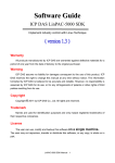
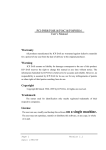
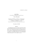
applications. The powerful functions of the LinCon-8000 embedded controller are
depicted in figure 1-1, which includes a VGA, USB(Card Reader, Camera …),
Mouse, Keyboard,
Compact flash card, Series ports(RS-232, RS-485),
Ethernet(Hub…) and many I/O slots in the picture. Presently, HTTP、FTP、Telnet、
SSH、SFTP Servers are built in and users can transfer files or use remote control with
the LinCon-8000 more conveniently. In network communication, wireless、Bluetooth
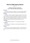
transfer and Modem、GPRS、ADSL、Firewall are also supported. Fig. 1-2 illustrates
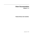
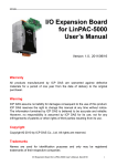
the outline of the LinCon-8000 with modules. Fig. 1-3 illustrates hardware architecture
of the LinCon-8000.
Quick Start of LinCon-8000:4
Fig. 1-1
Fig. 1-2
Quick Start of LinCon-8000:5
Fig. 1-3
Quick Start of LinCon-8000:6
2. INSTALLATION OF LINCON-8000 SDK
“LinCon-8000 SDK” consists of the following major items.
z
LinConSDK library files
z
LinConSDK include files
z
Demo files
z
GNU ToolChain
From
ftp://ftp.icpdas.com.tw/pub/cd/linconcd/napdos/linux/sdk/,
you
can
download the latest version of LinCon-8000 SDK and the Manual. And then follows
the below steps in order to install the development toolkit which has been provided by
ICP DAS for the easy application of the LinCon-8000 embedded controller platform.
2.1 Quick Installation of LinCon-8000 SDK
1. Please insert the installation CD into your CD-ROM driver.
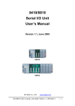
2. Run the “setup.exe” file under the folder \napdos\LinCon8000\. Then click on
the “Next” button, refer to Fig. 2-1.
Fig. 2 -1
Quick Start of LinCon-8000:7
3. Choose the option of “I accept the terms in the license agreement” and click
the “next” button, refer to Fig. 2-2 below.
Fig. 2-2
4. Input your user name and your organization’s name, then to click on the “Next”
buttion, refer to Fig 2-3.
Quick Start of LinCon-8000:8
Fig. 2-3
5. Then click on the “Install” button to install the LinCon-8000 SDK, refer to Fig
2-4.
Fig. 2-4
Quick Start of LinCon-8000:9
6. After successfully installing the software, please click on the “Finish” button to
finish the development toolkit installation, refer to Fig. 2-5
Fig. 2-5
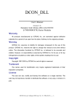
7. Open the “C:\cygwin\LinCon8k” folder and see the content. Refer to Fig 2-6.
Fig. 2-6
8. Start using the “LinCon-8000 Build Environment” by double clicking the
shortcut for the “LinCon-8000 Build Environment” on the desktop or by
clicking through “ Start ”>” Programs ”>” DAQPro ”>” LinCon-8000 SDK ”>”
LinCon-8000 Build Environment ” icon. Then a special DOSBOX will be
displayed in which we can compile applications for the LinCon-8000. refer to
Fig. 2-7.
Quick Start of LinCon-8000:10
Fig. 2-7
Once your Installation is complete, you can find the files for the library and demo
in the following paths.
The Libi8k.a path is “C:\cygwin\LinCon8k\lib".
The include files path is “C:\cygwin\LinCon8k\include”
The demo path is “C:\cygwin\LinCon8k\examples”.
Quick Start of LinCon-8000:11
3. The Architecture of LIBI8K.A in the LinCon-8000
The libi8k.a is a library file that is designed for I7000/8000/87000 applications
running in the Lincon-8000 Embedded Controller using the Linux OS. Users can
apply it to develop their own applications with C language. In order to assist users,
we provide many demo programs. Based on the demo programs, users can easily
understand how to use these functions and develop their own applications within a
short period of time.
The relationships among the libi8k.a and user’s applications are depicted as Fig.
3-1:
I-7000/8000/87000 series
Modules functions
Fig. 3-1
Functions for Lincon-8000 Embedded Controller are divided into sub-groups for
ease of use within the different applications.:
1.
System Information Functions
Quick Start of LinCon-8000:12
2.
3.
4.
5.
6.
7.
8.
Digital Input/Output Functions
Watch Dog Timer Functions
EEPROM Read/Write Functions
Analog Input Functions
Analog Output Functions
3-axis Encoder Functions
2-axis Stepper/Servo Functions
Quick Start of LinCon-8000:13
4. LINCON-8000 SYSTEM SETTINGS
In this section, we will introduce how to setup the LinCon-8000 configuration. Let
users can use the LinCon-8000 more easily.
4.1 Settings for the LinCon-8000 Network
The LinCon-8000 network setting includes two ways. One is DHCP and the other
is “Assigned IP”. DHCP is the default setting after the LinCon-8000 is produced and
this way is easy for users. However, if your network system is without DHCP server,
then users need to configure the network setting by using “Assigned IP”.
4.1.1 Setting the IP、Netmask and Gateway
(1) Using DHCP :
Boot up LinCon-8000 and click the “ start/xterm ” to open a “ command
Prompt ”. Type in “ vi /etc/network/interfaces ” to open the network setting file.
Remove “ # ” in the dhcp block and add “ # ” in the Assign IP block. Then type
“ :wq ” to save the setting. Type “ ifup eth0 “ to make the setting work. ( Refer to
the Fig 4-1 )
Fig 4-1
Quick Start of LinCon-8000:14
(2) Using “Assigned IP” :
Boot up LinCon-8000 and click the “ start/xterm ” to open a “command
line”. Type in “ vi /etc/network/interfaces ” to open the network setting file.
Remove “ # ” in the Assign IP block and add “ # ” in the dhcp block. Type ip、
netmask and gateway you want in the Assign IP block. Then type “ :wq ” to save
the setting. Type “ ifup eth0 “ to make the setting work. ( Refer to the Fig 4-2 )
Fig 4-2
After finish the LinCon network setting, users can type “ ifconfig “ to see the
network setting. ( Refer to the Fig 4-3 )
Quick Start of LinCon-8000:15
Fig 4-3
4.1.2 Setting of DNS
Boot up LinCon-8000 and click the “ start/xterm ” to open a “command line”.
Type in “ vi /etc/resolv.conf ” to open the DNS setting file. Type “ DNS server ” in the
“ nameserver “ field. Then type “ :wq ” to save the setting. Type “ reboot “ to reboot
the LinCon-8000 to make the setting work. ( Refer to the Fig 4-4 )
Fig 4-4
4.2 The CF Card Usage
The contents of CF Card in the LinCon-8000 is in the default path of /mnt/hda.
Therefore, users can access the files of CF Card in the directory.
Quick Start of LinCon-8000:16
4.2.1 Mount the CF Card
When you want to use the CF Card, you can insert the CF Card into the Slot of
CF Card in the LinCon-8000. ( Refer to Fig. 1-3 ) It will be auto-mounted in the
LinCon-8000, and you can access the files of CF Card in the /mnt/hda directory.
4.2.2 Umount the CF Card
Before you want to pull out the CF Card from the LinCon-8000, you need to type
the “ umount /mnt/hda “ command first. Then you can pull out the CF Card safely to
prevent the damage to CF Card.
4.3 The USB Device Usage
Before accessing the USB device, users need to mount the USB device to the
LinCon-8000. Because it will not auto-mount the USB device in the LinCon-8000.
4.3.1 Mount the USB Device
The steps are as follows :
(1) Change the path to /mnt, and then type “ mkdir usb “ to build a usb directory.
(2) Type “ mount
/dev/sda1
/mnt/usb “ to mount the USB device to the usb
directory and change the path to /mnt/usb. Then type “ ls ” and you can see
the content of USB device.
4.3.2 Umount the USB Device
Before you want to pull out the USB device from the LinCon-8000, you need to
type the “ umount /mnt/usb “ command first. Then you can pull out the USB device
safely to prevent the damage to USB device.
Quick Start of LinCon-8000:17
4.4 Adjust VGA Resolution
There are three modes -- 640x480、800x600、1024x768 supported in the LinCon
VGA resolution and the default setting is 800x600. If users want to change the VGA
resolution. Please follow below steps :
(1) Type “ vi /etc/init.d/fbman “ to open resolution setting file.
(2) If users want to set the resolution to be 1024x768. First, Add “#” in the
800x600 column and then remove “#” in the 1024x768 column. Type “ :wq “ to save
the setting. ( Refer to Fig 4-5 )
(3) Type “ Reboot “ to reboot LinCon-8000.
Fig 4-5
Quick Start of LinCon-8000:18
5. Demo of LinCon-8000 Modules With C Language
In this section, we will focus on examples for the description and application of
the control functions on the I-7000/I-8000/I-87k series modules for use in the
Lincon-8000. After you install the LinCon-8000 SDK, all these demo programs as
below are in the path of “c:/cygwin/lincon8k/examples”.
5.1 I-7k Modules DIO Control Demo
This demo – i7kdio.c will illustrate how to control DI/DO with the I-7050 module
(8 DO channels and 7 DI channels). The address and baudrate of the I-7050 module
in the RS-485 network are 02 and 9600 separately.
The result of this demo allows the DO channels 0 ~ 7 output and DI channel 2
input. The source code of this demo program is as follows:
#include<stdio.h>
#include<stdlib.h>
#include "msw.h"
char szSend[80], szReceive[80], ans;
WORD wBuf[12];
float fBuf[12];
/* ------------------------------------------------------------------- */
int main()
{
int wRetVal;
// Check Open_Com3
wRetVal = Open_Com(COM3, 9600, Data8Bit, NonParity, OneStopBit);
if (wRetVal > 0) {
printf("open port failed!\n");
return (-1);
}
// ***** 7050 DO && DI Parameter *******
wBuf[0] = 3;
// COM Port
Quick Start of LinCon-8000:19
wBuf[1] = 0x02;
wBuf[2] = 0x7050;
wBuf[3] = 0;
wBuf[4] = 100;
wBuf[5] = 0x0ff;
wBuf[6] = 0;
// Address
// ID
// CheckSum disable
// TimeOut , 100 msecond
// 8 DO Channels On
// string debug
// 7050 DO Output
wRetVal = DigitalOut(wBuf, fBuf, szSend, szReceive);
if (wRetVal)
printf("DigitalOut_7050 Error !, Error Code=%d\n", wRetVal);
printf("The DO of 7050 : %u \n", wBuf[5]);
// 7050 DI Input
DigitalIn(wBuf, fBuf, szSend, szReceive);
printf("The DI of 7050 : %u \n", wBuf[5]);
Close_Com(COM3);
return 0;
}
Follow the below steps to achieve the desired results:
STEP 1:( Write i7kdio.c )
Copy the above source code and save it with the name - i7kdio.c or get the file
from C:\cygwin\LinCon8k\examples\i7k.
STEP 2:( Compile i7kdio.c to i7kdio.exe )
Here we will introduce two methods to accomplish step 2.
< Method One > Using Batch File ( lcc.bat )
Execute Start>Programs>DAQPro>LinCon-8000 SDK> LinCon-8000 Build
Environment to open LinCon-8000 SDK and change the path to
C:\cygwin\LinCon8k\examples\i7k. Then type lcc i7kdio to compile i7kdio.c to
i7kdio.exe. ( refer to Fig. 5-1 )
Quick Start of LinCon-8000:20
Fig. 5-1
< Method Two > Using Compile Instruction
If you choose this method, change the path to C:\cygwin\LinCon8k\examples\i7k
and then type arm-linux-gcc -I../../include –lm –o i7kdio.exe i7kdio.c ../../lib/libi8k.a to
compile i7kdio.c to i7kdio.exe. ( refer to Fig. 5-2 )
Fig. 5-2
Quick Start of LinCon-8000:21
STEP 3:( Transfer i7kdio.exe to the LinCon-8000 )
Here we introduce two methods for achieving this purpose.
< Method One > Using FTP Software
(1) Open a FTP Software and add a ftp site of the LinCon-8000. The User_Name
and Password default value is “ root ”. Then click the “Connect” button to connect
to the ftp server of the LinCon-8000. (refer to Fig.5-3).
Fig.5-3
(2) Upload the file – i7kdio.exe to the LinCon-8000. (refer to Fig.5-4).
Quick Start of LinCon-8000:22
Fig.5-4
(3) Choose i7kdio.exe in the LinCon-8000 and Click the right mouse button to
choose the “ Permission ”option. Then type 777 into the Numeric blank textbox. (refer
to Fig.5-5 and refer to Fig.5-6 ).
Fig.5-5
Fig.5-6
Quick Start of LinCon-8000:23
< Method Two > Using DOS Command Prompt
Open DOS Command Prompt and type ftp IP Address of LinCon-8000 in order to
connect to the ftp server of the LinCon-8000. Then input User Name and Password
(root is the default value ) to login to the LinCon-8000. Type bin to make the file
transference in “binary” mode. Then type put
c:/cygwin/lincon8k/examples/i7k/i7kdio.exe i7kdio.exe to transfer the i7kdio.exe to the
LinCon-8000. After the “Transfer complete” message appears, the process of
transference would have been completed.( refer to Fig. 5-7 )
Fig. 5-7
STEP 4:( Telnet to the LinCon-8000 to execute i7kdio.exe )
Type telnet IP Address of LinCon-8000 into the remote control the LinCon-8000
and input your User Name and Password (root is the default value ) to login to the
LinCon-8000. And then type chmod 777 i7kdio.exe to make i7kdio.exe executable.
Type i7kdio.exe to execute i7kdio.exe. ( refer to Fig. 5-8 and Fig. 5-9 )
Fig. 5-8
Quick Start of LinCon-8000:24
Fig. 5-9
“ The DO of I-7050:255 ( =2^8-1 )” means DO channel 0 ~ 7 will output and
“ The DI of I-7050:123 ( =127-2^2 )” means there is input in DI channel 2.
5.2 I-7k Modules AIO Control Demo
This demo – i7kaio.c will illustrate how to control the AI/AO with the I-7017 (8 AI
channels ) and I-7021 modules ( 1 AO channel ). The address for the I-7021 and
I-7017 modules are in the RS-485 network where 05 and 03 are separate and the
baudrate is 9600.
The result of this demo allows the I-7021 module’s AO channel to output 3.5V
and the I-7017 ‘s AI channel 2 to input. The source code of this demo program is as
follows:
#include<stdio.h>
#include<stdlib.h>
#include "msw.h"
char szSend[80], szReceive[80];
WORD wBuf[12];
float fBuf[12];
/* ------------------------------------------------------------------- */
int main()
{
int i,j, wRetVal;
Quick Start of LinCon-8000:25
DWORD temp;
wRetVal = Open_Com(COM3, 9600, Data8Bit, NonParity, OneStopBit);
if (wRetVal > 0) {
printf("open port failed!\n");
return (-1);
}
//--- Analog output ---- **** 7021 -- AO ****
i = 0;
wBuf[0] = 3;
// COM Port
wBuf[1] = 0x05;
// Address
wBuf[2] = 0x7021;
// ID
wBuf[3] = 0;
// CheckSum disable
wBuf[4] = 100;
//wBuf[5] = i;
wBuf[6] = 0;
fBuf[0] = 3.5;
// TimeOut , 100 msecond
// Not used if module ID is 7016/7021
// Channel No.(0 to 1) if module ID is 7022
// Channel No.(0 to 3) if module ID is 7024
// string debug
// Analog Value
wRetVal = AnalogOut(wBuf, fBuf, szSend, szReceive);
if (wRetVal)
printf("AO of 7021 Error !, Error Code=%d\n", wRetVal);
else
printf("AO of 7021 channel %d = %f \n",i,fBuf[0]);
//--- Analog Input ---- ****
7017 -- AI ****
j = 1;
wBuf[0] = 3;
// COM Port
wBuf[1] = 0x03;
// Address
wBuf[2] = 0x7017;
// ID
wBuf[3] = 0;
// CheckSum disable
wBuf[4] = 100;
// TimeOut , 100 msecond
wBuf[5] = j;
// Channel of AI
wBuf[6] = 0;
// string debug
Quick Start of LinCon-8000:26
wRetVal = AnalogIn(wBuf, fBuf, szSend, szReceive);
if (wRetVal)
printf("AI of 7017 Error !, Error Code=%d\n", wRetVal);
else
printf("AI of 7017 channel %d = %f \n",j,fBuf[0]);
Close_Com(COM3);
return 0;
}
All the steps from programming to execution are the same as those in the section
5.1. The result of execution refers to Fig. 5-10.
Fig. 5-10
5.3 I-87k Modules DIO Control Demo
When using I-87k modules for I/O control of the LinCon-8000, the program will
be a little different, according to the location of I-87k modules. There are three
conditions for the location of the I-87k modules:
(1) When I-87k modules are in the LinCon-8000 slots, the two functions
“ Open_Slot ” and “ ChangeToSlot ”, must be added before using other
functions for the I-87k modules and the function of “Close_Slot() “ also needs
to be added to the end of the program. Please refer to demo in section 5.3.1.
Quick Start of LinCon-8000:27
(2) When I-87K modules are in the I-87k I/O expansion unit slots, then please
refer to the demo in section 5.3.2.
(3) When the I-87k modules are in the I-8000 controller slots, then the I-87k
modules will be regarded as I-8k modules and so please refer to I/O control of
I-8k modules in section 5.5.2
5.3.1 I-87k Modules in slots of LinCon-8000
This demo – i87kdio.c will illustrate how to control the DI/DO with the I-87054
module ( 8 DO channels and 8 DI channels). The I-87054 module is in slot 3 of the
LinCon-8000. The address and baudrate in the LinCon-8000 are constant and they
are 00 and 115200 respectively. The result of this demo lets DO channel 0 ~ 7 of
I-87054 output and DI channel 1 of I-87054 input. The source code of this demo
program is as follows:
#include<stdio.h>
#include<stdlib.h>
#include "msw.h"
char szSend[80], szReceive[80];
DWORD dwBuf[12];
float fBuf[12];
/* ------------------------------------------------------------------- */
int main()
{
int i, wRetVal;
DWORD temp;
//Check Open_Slot
wRetVal = Open_Slot(0);
if (wRetVal > 0) {
printf("open Slot failed!\n");
return (-1);
}
Quick Start of LinCon-8000:28
//Check Open_Com1
wRetVal = Open_Com(COM1, 115200, Data8Bit, NonParity, OneStopBit);
if (wRetVal > 0) {
printf("open port failed!\n");
return (-1);
}
//Choose Slot3
ChangeToSlot(3);
//--- digital output ---- **(DigitalOut_87k()**)
dwBuf[0] = 1;
// COM Port
dwBuf[1] = 00;
// Address
dwBuf[2] = 0x87054;
// ID
dwBuf[3] = 0;
// CheckSum disable
dwBuf[4] = 100;
dwBuf[5] = 0xff;
dwBuf[6] = 0;
// TimeOut , 100 msecond
// digital output
// string debug
wRetVal = DigitalOut_87k(dwBuf, fBuf, szSend, szReceive); // DO Output
printf("DO Value= %u", dwBuf[5]);
//--- digital Input ---**(DigitalIn_87k()**)
dwBuf[0] = 1;
// COM Port
dwBuf[1] = 00;
// Address
dwBuf[2] = 0x87054;
// ID
dwBuf[3] = 0;
// CheckSum disable
dwBuf[4] = 100;
// TimeOut , 100 msecond
dwBuf[6] = 0;
getch();
// string debug
DigitalIn_87k(dwBuf, fBuf, szSend, szReceive);
printf("DI= %u",dwBuf[5]);
//--- digital output ---** Close DO **
dwBuf[0] = 1;
// COM Port
dwBuf[1] = 00;
// Address
dwBuf[2] = 0x87054;
// ID
dwBuf[3] = 0;
// CheckSum disable
Quick Start of LinCon-8000:29
// DI Input
dwBuf[4] = 100;
// TimeOut , 100 msecond
dwBuf[5] = 0x00;
// digital output
dwBuf[6] = 0;
// string debug
getch();
// push any key to continue
wRetVal = DigitalOut_87k(dwBuf, fBuf, szSend, szReceive);
Close_Com(COM1);
Close_SlotAll();
return 0;
}
5.3.2 I-87k Modules in slots of I-87k I/O expansion unit
If the I-87k modules are in the slots of the I-87k I/O expansion unit, the above
program needs to be modified in three parts:
(4) The functions of Open_Slot() , ChangeToSlot(), Close_SlotAll() will be
deleted.
(5) The address and baudrate of I-87k modules in the network of RS-485 need
to be set by DCON Utility
(6) Open com1( internal serial port of LinCon-8000 ) will be modified to open
com3 ( RS-485 port of LinCon-8000 )
The address and baudrate of the I-87054 in the RS-485 network are set to be 06
and 9600 separately by the DCON Utility. The source code of this demo program –
i87kdio_87k.c is as follows:
#include<stdio.h>
#include<stdlib.h>
#include "msw.h"
char szSend[80], szReceive[80];
DWORD dwBuf[12];
float fBuf[12];
/* ------------------------------------------------------------------- */
int main()
{
Quick Start of LinCon-8000:30
int i, wRetVal;
DWORD temp;
//Check Open_Com3
wRetVal = Open_Com(COM3, 9600, Data8Bit, NonParity, OneStopBit);
if (wRetVal > 0) {
printf("open port failed!\n");
return (-1);
}
//--- digital output ---- **(DigitalOut_87k()**)
dwBuf[0] = 3;
dwBuf[1] = 06;
dwBuf[2] = 0x87054;
dwBuf[3] = 0;
// COM Port
// Address
// ID
// CheckSum disable
dwBuf[4] = 100;
dwBuf[5] = 0xff;
dwBuf[6] = 0;
// TimeOut , 100 msecond
// digital output
// string debug
wRetVal = DigitalOut_87k(dwBuf, fBuf, szSend, szReceive); // DO Output
printf("DO Value= %u", dwBuf[5]);
//--- digital Input ---**(DigitalIn_87k()**)
dwBuf[0] = 3;
// COM Port
dwBuf[1] = 06;
// Address
dwBuf[2] = 0x87054;
// ID
dwBuf[3] = 0;
// CheckSum disable
dwBuf[4] = 100;
// TimeOut , 100 msecond
dwBuf[6] = 0;
getch();
// string debug
DigitalIn_87k(dwBuf, fBuf, szSend, szReceive);
printf("DI= %u",dwBuf[5]);
//--- digital output ---** Close DO **
dwBuf[0] = 3;
// COM Port
dwBuf[1] = 06;
// Address
dwBuf[2] = 0x87054;
// ID
dwBuf[3] = 0;
// CheckSum disable
dwBuf[4] = 100;
// TimeOut , 100 msecond
Quick Start of LinCon-8000:31
// DI Input
dwBuf[5] = 0x00;
// digital output
dwBuf[6] = 0;
// string debug
getch();
// push any key to continue
wRetVal = DigitalOut_87k(dwBuf, fBuf, szSend, szReceive);
Close_Com(COM3);
return 0;
}
All the steps from programming to execution are the same as those in the section
5.1. The result of execution refers to Fig. 5-11.
Fig. 5-11
5.3.3 I-87k Modules in slots of I-8000 Controller
If the I-87k DI/DO modules are in the I-8000 controller slots, I-87k modules will
be regarded as I-8k modules and so please refer to DI/DO control of I-8k modules in
the section 5.5.
5.4 I-87k Modules AIO Control Demo
When using I-87k modules for I/O control of the LinCon-8000, according to the
location of the I-87k modules, the program will be a little different. There are three
conditions for the location of the I-87k modules:
(1) When the I-87k modules are in the LinCon-8000 slots, the two functions
Quick Start of LinCon-8000:32
“ Open_Slot ” and “ ChangeToSlot ” must be added before using the other
functions of the I-87k modules and the function “ Close_Slot() “ also needs to
be added to the end of the program. Please refer to the demo in section 5.4.1.
(2) When I-87K modules are in the I-87k I/O expansion unit slots, please refer
to the demo in section 5.4.2.
(3) When the I-87k modules are in the I-8000 controller slots, the I-87k modules
will be regarded as I-8k modules and so please refer to I/O control of I-8k
modules in section 5.6.2
5.4.1 I-87k Modules in slots of LinCon-8000
This demo – i87kaio.c will illustrate how to control the AI/AO with the I-87022
module ( 2 AO channels ) and the I-87017 module ( 8 AI channels ).The I-87022 and
I-87017 modules are plugged into slot 2 and slot 3 of the LinCon-8000 separately. The
address and baudrate in the LinCon-8000 are constant and they are 00 and 115200
separately. The result of this demo lets AO channel 0 of I-87022 output 2.5V and AI
channel 1 of I-87017 input. The source code of this demo program is as follows:
#include<stdio.h>
#include<stdlib.h>
#include "msw.h"
char szSend[80], szReceive[80];
DWORD wBuf[12];
DWORD wBuf7[12];
float fBuf[12];
/* ------------------------------------------------------------------- */
int main()
{
int i,j, wRetVal;
DWORD temp;
//Check Open_Slot
wRetVal = Open_Slot(0);
if (wRetVal > 0) {
Quick Start of LinCon-8000:33
printf("open Slot failed!\n");
return (-1);
}
//Check Open_Com1
wRetVal = Open_Com(COM1, 115200, Data8Bit, NonParity, OneStopBit);
if (wRetVal > 0) {
printf("open port failed!\n");
return (-1);
}
ChangeToSlot(2);
//--- Analog output ---i=0;
wBuf[0] = 1;
wBuf[1] = 0x00;
wBuf[2] = 0x87022;
wBuf[3] = 0;
wBuf[4] = 100;
wBuf[5] = i;
wBuf[6] = 0;
fBuf[0] = 2.5;
****
87022 -- AO
****
// COM Port
// Address
// ID
// CheckSum disable
// TimeOut , 100 msecond
// Channel Number of AO
// string debug
// AO Value
wRetVal = AnalogOut_87k(wBuf, fBuf, szSend, szReceive);
if (wRetVal)
printf("AO of 87022 Error !, Error Code=%d\n", wRetVal);
else
printf("AO of 87022 channel %d = %f \n",i,fBuf[0]);
ChangeToSlot(3);
//--- Analog Input ---- **** 87017 -- AI ****
j=1;
wBuf7[0] = 1;
// COM Port
wBuf7[1] = 0x00;
// Address
wBuf7[2] = 0x87017;
// ID
wBuf7[3] = 0;
// CheckSum disable
wBuf7[4] = 100;
// TimeOut , 100 msecond
wBuf7[5] = j;
//Channel Number of AI
Quick Start of LinCon-8000:34
wBuf7[6] = 0;
// string debug
wRetVal = AnalogIn_87k(wBuf7, fBuf, szSend, szReceive);
if (wRetVal)
printf("AI of 87017 Error !, Error Code=%d\n", wRetVal);
else
printf("AI of 87017 channel %d = %f \n",j,fBuf[0]);
Close_Com(COM1);
Close_SlotAll();
return 0;
}
5.4.2 I-87k Modules in slots of I-87k I/O expansion unit
If the I-87k modules are in slots of I-87k I/O expansion unit, the above program
needs to be modified in three parts:
(1) The functions of Open_Slot() , ChangeToSlot(), Close_SlotAll() will be
deleted.
(2) The addrss and baudrate of I-87k modules in the network of RS-485 need to
be set by DCON Utility
(3) Open com1( internal serial port of LinCon-8000 ) will be modified to open
com3 ( RS-485 port of LinCon-8000 )
The addresses I-87022 and I-87017 are in the RS-485 network and are set to be
01 and 02 separately and the baudrate is 9600 by DCON Utility. The source code of
this demo program – i87kaio_87k.c is as follows:
#include<stdio.h>
#include<stdlib.h>
#include "msw.h"
char szSend[80], szReceive[80];
DWORD wBuf[12];
DWORD wBuf7[12];
float fBuf[12];
Quick Start of LinCon-8000:35
/* ------------------------------------------------------------------- */
int main()
{
int i,j, wRetVal;
DWORD temp;
//Check Open_Com3
wRetVal = Open_Com(COM3, 9600, Data8Bit, NonParity, OneStopBit);
if (wRetVal > 0) {
printf("open port failed!\n");
return (-1);
}
//--- Analog output ---i=0;
wBuf[0] = 3;
wBuf[1] = 0x01;
wBuf[2] = 0x87022;
wBuf[3] = 0;
wBuf[4] = 100;
wBuf[5] = i;
wBuf[6] = 0;
fBuf[0] = 2.5;
****
87022 -- AO
****
// COM Port
// Address
// ID
// CheckSum disable
// TimeOut , 100 msecond
// Channel Number of AO
// string debug
// AO Value
wRetVal = AnalogOut_87k(wBuf, fBuf, szSend, szReceive);
if (wRetVal)
printf("AO of 87022 Error !, Error Code=%d\n", wRetVal);
else
printf("AO of 87022 channel %d = %f \n",i,fBuf[0]);
//--- Analog Input ---- ****
j=1;
wBuf7[0] = 3;
wBuf7[1] = 0x02;
wBuf7[2] = 0x87017;
wBuf7[3] = 0;
wBuf7[4] = 100;
87017 -- AI ****
// COM Port
// Address
// ID
// CheckSum disable
// TimeOut , 100 msecond
Quick Start of LinCon-8000:36
wBuf7[5] = j;
wBuf7[6] = 0;
//Channel Number of AI
// string debug
wRetVal = AnalogIn_87k(wBuf7, fBuf, szSend, szReceive);
if (wRetVal)
printf("AI of 87017 Error !, Error Code=%d\n", wRetVal);
else
printf("AI of 87017 channel %d = %f \n",j,fBuf[0]);
Close_Com(COM3);
return 0;
}
All the steps from programming to execution are the same as those in the section
5.1. The result of execution refers to Fig. 5-12.
Fig. 5-12
5.4.3 I-87k Modules in slots of I-8000 Controller
If the I-87k AI/AO modules are in slots of I-8000 controller, I-87k modules will be
regarded as I-8k modules and refer to AI/AO control of I-8k modules in the section 5.6.
5.5 I-8k Modules DIO Control Demo
I8000.c of Libi8k.a is the source file for i8k modules in slots of I-8000 controller.
Quick Start of LinCon-8000:37
Slot.c of Libi8k.a is the source file for i8k modules in slots of LinCon-8000. Therefore
the functions for i8k modules in slots of LinCon-8000 and in slots of I-8000 controller
are different completely.
5.5.1 I-8k Modules in slots of LinCon-8000
In this section, this demo program – i8kdio.c will introduce how to control the
DI/DO with the I-8055 ( 8 DO channels and 8 DI channels ) module and it is plugged
into slot 3 of the LinCon-8000.
The address and baudrate in the LinCon-8000 are constant and they are 00 and
115200 separately. The result of this demo lets DO channel 0 ~7 of I-8055 output and
DI channel 0 of I-8055 input. The source code of this demo program is as follows:
#include<stdio.h>
#include<stdlib.h>
#include "msw.h"
char szSend[80], szReceive[80];
DWORD dwBuf[12];
float fBuf[12];
/* ------------------------------------------------------------------- */
int main()
{
int i,j, wRetVal;
WORD DOval,temp;
wRetVal = Open_Slot(3);
if (wRetVal > 0) {
printf("open Slot failed!\n");
return (-1);
}
//I-8055_DO
DO_8(3,255);
printf("DO of I-8055 = 0x%x \n", 255);
Quick Start of LinCon-8000:38
//I-8055_DI
printf("DI of I-8055 = %x",DI_8(3));
Close_Slot(3);
return 0;
}
All the steps from programming to execution are the same as those in the section
5.1. The result of execution refers to Fig. 5-13.
Fig. 5-13
5.5.2 I-8k Modules in slots of I-8000 Controller
In this section, this demo program – i8kdio_8k.c will illustrate how to control the
DI/DO with the I-8055 ( 8 DO channels and 8 DI channels ) module. Please follow the
below steps to configure the hardware:
(1) Put the I-8055 module in slot 0 of I-8000 controller.
(2) Install 8k232.exe or R232_300.exe to flash memory of I-8000 controller as
firmware.
(3) Connect the com2 of LinCon-8000 to the com1 of I-8000 controller with the
RS-232 cable.
The address of I-8000 controller is 01 and the baudrate is 115200 that can be
modified by DCON Utility. The result of this demo lets DO channel 0 ~7 of I-8055
output and DI channel 0 of I-8055 input. The source code of this demo program is as
follows:
Quick Start of LinCon-8000:39
#include<stdio.h>
#include<stdlib.h>
#include "msw.h"
char szSend[80], szReceive[80];
DWORD dwBuf[12];
float fBuf[12];
/* ------------------------------------------------------------------- */
int main()
{
int i, wRetVal;
DWORD temp;
//Check Open_Com2
wRetVal = Open_Com(COM2, 115200, Data8Bit, NonParity, OneStopBit);
if (wRetVal > 0) {
printf("open port failed!\n");
return (-1);
}
//--- digital output ---- **(DigitalOut_8K()**)
dwBuf[0] = 2;
// COM Port
dwBuf[1] = 01;
// Address
dwBuf[2] = 0x8055;
// ID
dwBuf[3] = 0;
// CheckSum disable
dwBuf[4] = 100;
// TimeOut , 100 msecond
dwBuf[5] = 0xff;
// digital output
dwBuf[6] = 0;
// string debug
dwBuf[7] = 1;
// slot number
wRetVal = DigitalOut_8K(dwBuf, fBuf, szSend, szReceive);
if (wRetVal)
printf("DO of 8055 Error !, Error Code=%d\n", wRetVal);
else
printf("DO of 8055 = 0x%x" ,dwBuf[5]);
Quick Start of LinCon-8000:40
//--- digital Input ---**(DigitalIn_8K()**)
dwBuf[0] = 2;
// COM Port
dwBuf[1] = 01;
// Address
dwBuf[2] = 0x8055;
// ID
dwBuf[3] = 0;
// CheckSum disable
dwBuf[4] = 100;
// TimeOut , 100 msecond
dwBuf[6] = 0;
dwBuf[7] = 1;
// string debug
// slot number
getch();
DigitalIn_8K(dwBuf, fBuf, szSend, szReceive);
printf("DI = %u",dwBuf[5]);
//--- digital output ---dwBuf[0] = 2;
dwBuf[1] = 01;
dwBuf[2] = 0x8055;
dwBuf[3] = 0;
dwBuf[4] = 100;
dwBuf[5] = 0x00;
dwBuf[6] = 0;
dwBuf[7] = 1;
** Close DO **
// COM Port
// Address
// ID
// CheckSum disable
// TimeOut , 100 msecond
// digital output
// string debug
// slot number
getch();
// push any key to continue
wRetVal = DigitalOut_8K(dwBuf, fBuf, szSend, szReceive);
Close_Com(COM2);
return 0;
}
All the steps from programming to execution are the same as those in the section
5.1. The result of execution refers to Fig. 5-14.
Quick Start of LinCon-8000:41
Fig. 5-14
5.6 I-8k Modules AIO Control Demo
I8000.c of Libi8k.a is the source file for i8k modules in slots of I-8000 controller.
Slot.c of Libi8k.a is the source file for i8k modules in slots of the LinCon-8000.
Therefore the functions for the i8k modules in LinCon-8000 slots and in the I-8000
controller slots are completely different.
7.6.1 I-8k Modules in slots of LinCon-8000
In this section, this demo program – i8kaio.c will illustrate how to control the
AI/AO with the I-8024 ( 4 AO channels ) and I-8017 ( 8 AI channels ) module and they
are in slot 1 and slot 2 of the LinCon-8000 separately.
The address and baudrate in the LinCon-8000 are constant and they are 00 and
115200 separately. The result of this demo lets AO voltage channel 0 of I-8024 output
5.5V and AI channel 2 of I-8017H input. The source code of this demo program is as
follows:
#include<stdio.h>
#include<stdlib.h>
#include "msw.h"
char szSend[80], szReceive[80];
DWORD dwBuf[12];
float fBuf[12];
Quick Start of LinCon-8000:42
/* ------------------------------------------------------------------- */
int main()
{
int i, wRetVal,j;
float fAi;
int hAi, chAi, Succ;
int Arr_hAi[5];
float Arr_fAi[5];
//I-8024
wRetVal = Open_Slot(1);
if (wRetVal > 0) {
printf("open Slot failed!\n");
return (-1);
}
//I8024 Initial
I8024_Initial(1);
//I8024_AO Output
I8024_VoltageOut(1,0,5.5);
Close_Slot(1);
/***************************************/
//I-8017H
wRetVal = Open_Slot(2);
if (wRetVal > 0) {
printf("open Slot failed!\n");
return (-1);
}
//I8017H Initial
I8017_Init(2);
//I8017H _Channel Setup
I8017_SetChannelGainMode(2,2,0,0);
// First Method:Get AI Value
hAi = I8017_GetCurAdChannel_Hex(2);
//Get Not-calibrated AI Hex Value
Quick Start of LinCon-8000:43
printf("8017_AI_not_Cal_Hex =%x\n",hAi);
fAi = HEX_TO_FLOAT_Cal(hAi,2,0);
to calibrated AI Float Value
printf("8017_AI_Cal_Float =%f\n\n",fAi);
//Not-calibrated AI Hex Value modify
// Second Method:Get AI Value
hAi = I8017_GetCurAdChannel_Hex_Cal(2);
printf("8017_AI_Cal_Hex =%x\n",hAi);
fAi = CalHex_TO_FLOAT(hAi,0);
to Calibrated AI Float Value
printf("8017_AI_Cal_Float =%f\n\n",fAi);
//Get Calibrated AI Hex Value
//Calibrated AI Hex Value modify
// Third Method:Get AI Value
fAi = I8017_GetCurAdChannel_Float_Cal(2); //Get Calibrated AI Float Value
printf("8017_AI_Cal_Float =%f\n\n\n",fAi);
Close_Slot(2);
return 0;
}
All the steps from programming to execution are the same as those in the section
5.1. The result of execution refers to Fig. 5-15.
Fig. 5-15
Quick Start of LinCon-8000:44
5.6.2 I-8k Modules in slots of I-8000 Controller
In this section, this demo program – i8kaio_8k.c will introduce how to control the
AI/AO with the I-8024 ( 4 AO channels ) and I-8017 ( 8 AI channels ) module and they
are plugged into slot 0 and slot 1 of the I-8000 controller separately. Please follow the
below steps to configure the hardware:
(1) Put the I-8024 and I-8017 modules in slot 0 and slot 1 of I-8000 controller.
(2) Install 8k232.exe or R232_300.exe to flash memory of I-8000 controller as
firmware.
(3) Connect com2 of LinCon-8000 to com1 of I-8000 controller with RS-232
cable.
The address and baudrate of I-8000 controller are 01 and 115200 that can be
modified by DCON Utility. The result of this demo lets AO voltage channel 0 of 8024
output 3.5V and AI channel 2 of 8017H input. The source code of this demo program
is as follows:
#include<stdio.h>
#include<stdlib.h>
#include "msw.h"
char szSend[80], szReceive[80];
DWORD wBuf[12];
float fBuf[12];
/* ------------------------------------------------------------------- */
int main()
{
int i,j, wRetVal;
DWORD temp;
wRetVal = Open_Com(COM2, 115200, Data8Bit, NonParity, OneStopBit);
if (wRetVal > 0) {
printf("open port failed!\n");
return (-1);
}
//--- Analog output ---- ****
8024 -- AO ****
Quick Start of LinCon-8000:45
i = 0;
wBuf[0] = 2;
wBuf[1] = 0x01;
wBuf[2] = 0x8024;
wBuf[3] = 0;
wBuf[4] = 100;
wBuf[5] = i;
wBuf[6] = 0;
wBuf[7] = 0;
fBuf[0] = 3.5;
// COM Port
// Address
// ID
// CheckSum disable
// TimeOut , 100 msecond
// Channel No. of AO
// string debug
// Slot Number
wRetVal = AnalogOut_8K(wBuf, fBuf, szSend, szReceive);
if (wRetVal)
printf("AO of 8024 Error !, Error Code=%d\n", wRetVal);
else
printf("AO of 8024 channel %d = %f \n",i,fBuf[0]);
//--- Analog Input ---- **** 8017H -- AI ****
j = 2;
wBuf[0] = 2;
// COM Port
wBuf[1] = 0x01;
// Address
wBuf[2] = 0x8017;
// ID
wBuf[3] = 0;
// CheckSum disable
wBuf[4] = 100;
// TimeOut , 100 msecond
wBuf[5] = j;
// Channel of AI
wBuf[6] = 0;
// string debug
wBuf[7] = 1;
// Slot Number
wRetVal = AnalogIn_8K(wBuf, fBuf, szSend, szReceive);
if (wRetVal)
printf("AI of 8017H Error !, Error Code=%d\n", wRetVal);
else
printf("AI of 8017H channel %d = %f \n",j,fBuf[0]);
Close_Com(COM2);
return 0;
}
Quick Start of LinCon-8000:46
All the steps from programming to execution are the same as those in the section
5.1. The result of execution refers to Fig. 5-16
Fig. 5-16
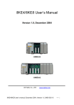
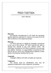
5.7 Conclusion of Functions and Source Files of Modules
Fig. 5-17 is the table of communication functions for the I-7000/I-8000/I-87000
modules in different locations. When using the ICPDAS modules in the LinCon-8000,
this table will be helpful to let users understand which functions of communication
should be used.
Fig. 5-17
Quick Start of LinCon-8000:47
6. Additional Support
In this chapter, ICPDAS provides extra module supported and instructions to
enhance LinCon-8000 functionality and affinity.
6.1 Support N-Port Module ( i-8114, i-8112 )
i-8114 and i-8112 modules provide four and two serial ports separately. Users
can insert them in the slots of the LinCon-8000. In this way, users can use more serial
ports in the LinCon-8000 and the expanded maximum number of serial port in the
LinCon-8000 is twenty-eight. Because it is multi-tasking in the LinCon, users can
control all the serial ports simultaneously. The serial port number of i-8114 and
i-8112 are figured in the fig.6-1 and fig.6-2 and it is fixed according to their slot
position in the LinCon-8000.
fig.6-1
Quick Start of LinCon-8000:48
fig.6-2
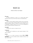
Fig.6-3 is the serial port number corresponding to the device name in the
LinCon-8000.
fig.6-3
The demo - i7kdio_8114.c will illustrate how to use the i-8114 module in the
LinCon-8000. In this demo, we will control the I-7044 ( 8 DO channels and 4 DI
channels ) through the second serial port of i-8114 plugged in the slot 2 of the
LinCon-8000. The address and baudrate of the I-7044 module in the RS-485 network
are 02 and 115200 separately. Fig.6-4 is the control diagram.
Quick Start of LinCon-8000:49
fig.6-4
The result of this demo allows users to control which DO channels’ state on and
return the DI channels’ state. The source code of this demo program is as follows:
#include<stdio.h>
#include<stdlib.h>
#include "msw.h"
char szSend[80], szReceive[80], ans;
WORD wBuf[12];
float fBuf[12];
/* ------------------------------------------------------------------- */
int main()
{
int wRetVal,j=0;
char i[10];
// Check Open_Com9 in I-8114
wRetVal = Open_Com(COM9, 115200, Data8Bit, NonParity, OneStopBit);
if (wRetVal > 0) {
printf("open port failed!\n");
return (-1);
}
Quick Start of LinCon-8000:50
//
*****
7044 DO & DI Parameter *******
wBuf[0] = 9;
wBuf[1] = 0x02;
wBuf[2] = 0x7044;
wBuf[3] = 0;
wBuf[4] = 100;
wBuf[6] = 0;
// COM Port
// Address
// ID
// CheckSum disable
// TimeOut , 100 msecond
// string debug
// 7044 DO
while(j!=113) {
printf("Input DO value or press 'q' to quit!! -> ");
scanf("%s",i);
if (i[0]=='q') {
wBuf[5] = 0;
// All DO Channels Off
wRetVal = DigitalOut(wBuf, fBuf, szSend, szReceive);
break;
}
j=atoi(i);
if (j>=0 & j<=255)
wBuf[5] = j;
else if (j>255)
wBuf[5] = 255;
// DO Channels On
wRetVal = DigitalOut(wBuf, fBuf, szSend, szReceive);
if (wRetVal)
printf("DigitalOut_7044 Error !, Error Code=%d\n", wRetVal);
printf("The DO of 7044 : %u \n", wBuf[5]);
// 7044 DI
DigitalIn(wBuf, fBuf, szSend, szReceive);
printf("The DI of 7044 : %u \n", wBuf[5]);
}
Close_Com(COM9);
return 0;
}
Quick Start of LinCon-8000:51
All the steps from programming to execution are the same as those in the section
5.1. The result of execution refers to Fig. 6.5.
Fig. 6.5
6.2 I-talk Utility
The i-Talk utility provides sixteen instructions that make it convenient for
users to access the modules and hardware in the LinCon-8000 and they are placed in
the path - /usr/local/bin. Fig. 6-6 describes the functions of i-Talk utility.
Quick Start of LinCon-8000:52
Fig. 6-6
Fig. 6-7 lists the demo that show how to use the I-talk utility. In the demo,the
I-8024 ( AO Module ) 、I-8017H ( AI Module ) and I-8055 ( DIO Module) are all used
and they are plugged into the slots 1、2 and 3 of the LinCon seperately.
Quick Start of LinCon-8000:53
Fig. 6-7
Users can also type in the instructions name and it will show the instructions
usage.
Quick Start of LinCon-8000:54
Fig. 6-7
Users can also type the name of instructions and it will show the usage of
instructions.
6.3 Crash Free Support
If it is unfortunate, the LinCon-8000 is crashed and can’t reboot. Please follow
the steps to make the LinCon recover the normal state :
(1) Reboot the LinCon-8000.
(2) When the “ boot up screen “ shows up, connect the pin 1 and pin 5 of the
second row of any slot with a wire immediately. ( Refer to the Fig. 6-8 )
(3) The LinCon-8000 will boot up with its correct “ /etc “ directory built in and
user’s “ /etc “ directory will be placed to the path – “ /tmp/etc “. When the
LinCon-8000 boot up successfully, users should copy the correct files in the
/etc to the path - /tmp/etc or correct the files in the /tmp/etc.
(4) After the correction, remove the connection wire and reboot LinCon-8000
again.
Quick Start of LinCon-8000:55
Fig. 6-8
6.4 GUI Funtion Support
Now “ X-window “ is supported in the LinCon-8000 and when the LinCon-8000
boot up, the GUI like “ Windows screen “ will show up. The most important thing is
that users can write GUI programs and run them in the LinCon-8000. The GUI Library
in the LinCon-8000 is provided with GTK+ v1.2 & v2.0 Library. Therefore users can
design their own “ SCADA “ screen by the GTK+ Library in the LinCon-8000. In the
meanwhile, we provide some GUI demo programs to control I/O modules of ICPDAS
and assist users to develop own GUI programs quickly. These demo programs are
placed in the path - C:\cygwin\LinCon8k\examples\gui after users install the
LinCon-8000 SDK. ( Refer to the Fig. 6-9 )
Except GTK+ GUI Function, “ Java GUI “ is also supported in the LinCon-8000.
So if users are familiar with Java, users can also use Java to develop own GUI
programs. But just Awe and Swing v1.1 elements below are supported in the
LinCon-8000. To execute Java GUI program – Stylepad.jar in the LinCon-8000, users
just type in “ java -jar Stylepad.jar -cp .:Stylepad.jar “. Then it will take some time to
run up the Java GUI program.
Quick Start of LinCon-8000:56
Fig. 6-9
6.5 ScreenShot Support
There is a screenshot program - “ fbshot “ built in to let users to catch the
LinCon-8000 screen conveniently. Users just type in “ fbshot -d /dev/fb0
/mnt/hda/catch1.png “ and the screen will be catched and saved to the file -
/mnt/hda/catch1.png. If users want to take a look the picture, just type in “ iv
/mnt/hda/catch1.png “. If users want to know the detailed parameters of fbshot, just
type in “ fbshot --help ”.
6.6 WebCAM Support
WebCAM is also supported in the LinCon-8000 and Logitech brand works
successfully now. Other brands will need to do a test. Please follow the steps to make
the Webcam work smoothly :
(1) Connect the webcam to the LinCon-8000 with “ USB Interface “.
(2) Reboot the LinCon-8000.
(3) Open a “ Command Prompt “. Type in “ insmod pwcx.o “ to load the
gqcam program decompressor and then type in “ gqcam “ to see the
webcam screen. If users want to know the detailed parameters of gqcam, just
type in “ gqcam --help ”.
Quick Start of LinCon-8000:57
If users want to catch the picture through webcam, users can use gqcam program
to do that. Please follow the steps as below :
(1) Click “ File/Save Image… “
(2) At “ Gqcam: Save Image “ screen, input the path and file name in the “ File
Field “ and then click “ OK “ button.
6.7 Network Support
There are many network functions already built in the LinCon-8000. Here are the
network functions supported in the LinCon-8000 :
(1) Support UPnP :
UPnP is “ Universal Plug and Play “ and allows automatic discovery and
control of services available on the network from other devices without user
intervention. Devices that act as servers can advertise their services to clients. Client
systems, known as control points, can search for specific services on the network.
When they find the devices with the desiredservices, the control points can retrieve
detailed descriptions of the devices and services and interact from that point on.
(2) Support VPN
VPN is “ Virtual Private Network “ and describes a network that includes
secure remote access for client computers. It can be explained best by looking at its
parts. “ Virtual “ describes the fact that the network doesn't need to be physically
connected directly. The “ Private “ confirms that the data is encrypted and can only
be viewed by a defined group. The last word, “ Network “, means that the users
configured for VPN can be connected and share files or information. So it's extremely
difficult for anyone to snoop on confidential information through VPN. ( Refer to the
Fig. 6-10 )
Quick Start of LinCon-8000:58
Fig. 6-10
(3) Support QoS
QoS is “ Quality of Service “. It means when the kernel has several packets to
send out over a network device, it has to decide which ones to send first, which ones
to delay, and which ones to drop. With Linux QoS subsystem, it is possible to make
very flexible traffic control. Let users be able to control flow rate of assigned port to
improve the network quality.
(4) Support Wireless LAN
“ Wireless communication “ is a networking technology allowing the
connection of computers without any wires and cables, mostly using radio technology
(and sometime infrared). It's called LAN because the range targeted is small
( generally within an office, a building, a store, a small campus, a house... ). This
technology is slowly growing and Linux is able to take advantage of some of the
wireless networks available.
(5) Support Dual LAN
Dual LAN means that users can combine wireless and cable network together
through LinCon-8000. Therefore the communication between Cable LAN and
Quick Start of LinCon-8000:59
Wireless LAN. If one of these LANs can connect to internet, then all the PC can
connect to internet. ( Refer to Fig. 6-11 )
Fig. 6-11
(6) Support BlueTooth
The Bluetooth wireless technology is a worldwide specification for a small-form
factor, low-cost radio solution that provides links between mobile computers, mobile
phones, other portable handheld devices, and connectivity to the Internet. Now
“ BlueZ “ is built in the LinCon-8000 and provides support for the core Bluetooth
layers and protocols. It is flexible, efficient and uses a modular implementation.
(7) Support Modem / GPRS / ADSL
LinCon-8000 can be connected to the Internet with “ Modem “, “ GPRS “ or
“ ADSL “ mode. The setup method is described separately as follows :
[ Modem ]
[ GPRS ]
The default GPRS baudrate is “ 115200 “ in the LinCon, so if users finish the
setting of gprs modem and connect the gprs modem to the COM 2 of
LinCon-8000, just type in “ pppd call wavecom “ and then LinCon-8000 will be
connected to the internet automatically. Remember that the network interface
card of LinCon should stop first, just type in “ ifdown eth0 “ to stop it. If users
type in “ ifconfig “ will see the “ ppp0 “ option.
Quick Start of LinCon-8000:60
[ ADSL ]
Users need to type in “ adsl-setup “ first to setup ADSL options. After that,
users need to type in “ adsl-connect “ to make LinCon-8000 connect to the
internet. If users want to stop adsl connection, just type in “ adsl-stop “.
(8) Support Firewall ( iptables function )
A firewall can controls outside access to a local network, locking out intruders to
ensure your systems and data safe on the inside, even against an intentional attack
from outside network.
(9) Provide Web Browser
Users can see the Web Page by using the Web Browser built in the
LinCon-8000. Just type in “ dillo “ to open the web browser and input the web site
address. ( Refer to Fig 6-12 )
Fig 6-12
(10) Provide Apache Server
The Web Server - “ Apache Server “ has been built in the LinCon-8000.
Quick Start of LinCon-8000:61
These files are placed in the path - /mnt/hda/opt/apache2. Users can type in
like “ http://192.168.0.200 “ in web browser with PC to attempt to connect to the
web server in the LinCon-8000. If it returns a successful web page, it means the
web server in the LinCon-8000 has been started.
These files are placed in the CF Card. So if users want to use the Web Server
in the LinCon-8000, users must plug in CF Card in the LinCon-8000 and the
“ apache2 ” directory must be in the “ /opt “ directory of CF Card. Then when
users boot up the LinCon-8000, the Web Server will start automatically.
6.8 Other Optional Function
These optional functions are listed below all supported in the LinCon-8000. Users
can choose which function to be used in the LinCon-8000 and just copy the
corresponding file directory to the “ opt “ directory of CF Card. Then reboot
LinCon-8000 and the function users choose will work automatically.
(1) Support MySQL
MySQL is a small database server and it is “ Relational DataBase Management
System ( RDBMS ) “. By using MySQL, users can add or delete data easily and it is
open source and supports many platforms, like UNIX、Linux or Windows operating
system. If users want to use MySQL in the LinCon-8000, remember to copy the
“ mysql “ directory to the “ opt “ directory of CF Card and reboot LinCon-8000.
(2) Support PHP
PHP is a kind of “ open source script language “ and used to design active web
page. When PHP combined with MySQL are cross-platform. It means that users can
develop in Windows and serve on a Linux platform. ( Refer to Fig 11-11 )
PHP has been built in the LinCon-8000 Kernel so users just boot up LinCon-8000
and can use PHP directly in the LinCon-8000.
Quick Start of LinCon-8000:62
Fig 11-11
(3) Support Perl
Perl(Practical Extraction and Report Language)is also a “ open source script
language “ and has been built in the LinCon-8000 Kernel so users just boot up
LinCon-8000 and can use Perl directly in the LinCon-8000.
Quick Start of LinCon-8000:63