1
Software Guide
ICP DAS LinPAC-5000 SDK
Implement industry control with Linux Technique
Warranty
All products manufactured by ICP DAS are warranted against defective materials for a
period of one year from the date of delivery to the original purchaser.
Warning
ICP DAS assume no liability for damages consequent to the use of this product. ICP
DAS reserves the right to change this manual at any time without notice. The information
furnished by ICP DAS is believed to be accurate and reliable. However, no responsibility is
assumed by ICP DAS for its use, or for any infringements of patents or other rights of third
parties resulting from its use.
Copyright
Copyright © 2011 by ICP DAS Co., Ltd. All rights are reserved.
Trademark
Names are used for identification purposed and only maybe registered trademarks of
their respective companies.
License
.
The user can use, modify and backup this software on a single machine
The user may not reproduce, transfer or distribute this software, or any copy, in whole or in
part.
LinPAC-5000 SDK Manual:1
Contents
1. Introduction ............................................................................................5
2. Installation of LinPAC-5000 SDK.........................................................7
2.1 Quick Installation of LinPAC-5000 SDK .............................................................7
2.2 The LinPAC-5000 SDK Introduction ...................................................................9
2.2.1 Introduction to Cygwin ..................................................................................................10
2.2.2 Introduction to Cross-Compilation...............................................................................10
2.2.3 Download the LinPAC-5000 SDK .................................................................................10
3.The Architecture of library in the LinPAC-5000................................11
4. LinPAC-5000 System Settings .............................................................13
4.1 Settings for the LinPAC-5000 Network ..............................................................13
4.1.1 Setting the IP、Netmask and Gateway ........................................................................13
4.1.2 Setting of DNS.................................................................................................................15
4.2 microSD Card Usage.............................................................................................15
4.2.1 Mount microSD Card.....................................................................................................15
4.2.2 Umount microSD Card ..................................................................................................16
4.2.3 Scan and repair microSD Card .....................................................................................16
4.3 USB Storage Device Usage ...................................................................................17
4.3.1 Mount USB Storage Device............................................................................................17
4.3.2 Umount USB Storage Device .........................................................................................17
4.4 Adjust VGA Resolution ........................................................................................17
4.5 Running applications automatically at boot time ..............................................18
4.5.1 Making program run at boot time ................................................................................18
4.5.2 Disabling program run at boot time .............................................................................20
4.6 Automatic login .....................................................................................................21
5. Instructions for the LinPAC-5000.......................................................22
5.1 Basic Linux Instructions.......................................................................................22
5.1.1 ls : list the file information -> ( like dir in DOS ) ...............................................22
5.1.2 cd directory : Change directory -> ( like cd in DOS )........................................22
5.1.3 mkdir:create the subdirectory -> ( like md in DOS ) ......................................22
5.1.4 rmdir:delete(remove) the subdirectory and it must be empty ->
( like rd in DOS )......................................................................................................................22
5.1.5 rm : delete file or directory -> ( like del or deltree in DOS ) .............................22
LinPAC-5000 SDK Manual:2
5.1.6
5.1.7
5.1.8
5.1.9
5.1.10
5.1.11
5.1.12
5.1.13
5.1.14
5.1.15
5.1.16
5.1.17
5.1.18
5.1.19
5.1.20
5.1.21
cp:copy file -> ( like copy in DOS ) ...................................................................23
mv:move or rename file or directory -> ( like move or ren in DOS ) ............23
pwd:show the current path ......................................................................................23
who:show the on-line users ......................................................................................23
chmod:change authority of file..............................................................................23
uname:show the version of linux ...........................................................................23
ps:show the procedures that execute now.............................................................24
ftp:transfer file ........................................................................................................24
telnet:connect to other PC......................................................................................24
date:show date and time.........................................................................................24
netstat:show the state of network ..........................................................................24
ifconfig:show the ip and network mask ( like ipconfig in DOS )........................24
ping:check to see if the host in the network is alive.............................................24
clear:clear the screen ..............................................................................................24
passwd:change the password .................................................................................24
reboot:reboot the LinPAC......................................................................................24
5.2 General GCC Instructions ...................................................................................25
5.2.1 Compile without linking the LinPAC-5000 library .....................................................26
5.2.2 Compile with linking the LinPAC-5000 library ( libi8k.a ) ........................................26
5.3 A Simple Example – Helloworld.c .......................................................................27
5.4 i-Talk Utility ..........................................................................................................32
6. LIBI8K.A...............................................................................................34
6.1 System Information Functions.............................................................................36
6.2 Watch Dog Timer Functions................................................................................57
6.3 EEPROM Read/Write Functions ........................................................................60
6.4 Digital Input/Output Functions ...........................................................................64
6.4.1 I-7000 series modules .....................................................................................................64
6.5 Analog Input Functions ........................................................................................81
6.5.1 I-7000 series modules .....................................................................................................81
6.6 Analog Output Functions .....................................................................................93
6.6.1 I-7000 series modules .....................................................................................................93
5.7 Error Code Explanation .....................................................................................104
7. Demo of LinPAC-5000 Modules With C Language.........................105
7.1 I-7k Modules DIO Control Demo ......................................................................105
7.2 I-7k Modules AIO Control Demo ......................................................................110
7.3 Conclusion of Module Control Demo................................................................112
7.4 Timer Function Demo.........................................................................................113
8. Introduction of LinPAC-5000 Serial Ports.......................................114
LinPAC-5000 SDK Manual:3
8.1 Introduction of COM1 Port of LinPAC-5000 ..................................................115
8.2 Introduction of COM2 Port of LinPAC-5000 ..................................................116
8.3 Introduction of COM3 Port of LinPAC-5000 ..................................................117
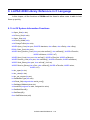
9. LinPAC-5000 Library Reference in C Language ............................118
9.1 List Of System Information Functions .............................................................118
9.2 List Of Digital Input/Output Functions............................................................119
9.3 List Of Watch Dog Timer Functions.................................................................119
9.4 List Of EEPROM Read/Write Functions .........................................................119
9.5 List Of Analog Input Functions.........................................................................119
9.6 List Of Analog Output Functions ......................................................................120
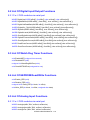
10. Additional Support ...........................................................................121
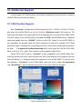
10.1 GUI Funtion Support........................................................................................121
10.1.1 Disable X-window.......................................................................................................122
10.1.2 Enable X-window........................................................................................................122
10.2 ScreenShot Support ..........................................................................................122
10.3 WebCAM Support ............................................................................................123
10.4 Screen Resolution Setting.................................................................................123
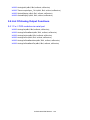
10.5 Network Support...............................................................................................124
10.6 Audio Function ..................................................................................................128
10.7 USB to RS-232 Support ....................................................................................129
10.8 Other Optional Function ..................................................................................130
Appendix A. Service Information .........................................................132
Internet Service : .......................................................................................................132
Manual Revision : .....................................................................................................132
LinPAC-5000 SDK Manual:4
1. Introduction
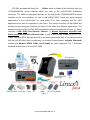
LinPAC-5000 is the new generation Linux-based PAC from ICP DAS and is equipped
with a PXA270 CPU (520 MHz) running a Linux kernel 2.6.19 operating system, variant
connectivity (VGA, USB, Ethernet, RS-232/485 and audio port) and contains an optional I/O
expansion board that can be used for implementing various I/O functions, such as D/I, D/O,
A/D, D/A, Timer/Counter, UART, flash memory, etc.
The LP-5000 had the advantages of good control system. These advantages include:
stability, small core size, I/O expansion board optional, support for Web services
(Web/FTP/Telnet/SSH server), support
for multiple development environments (LinPAC
SDK for Linux and Windows environment using the GNU C language, JAVA, GUI software),
etc. They give you all of the best features of both traditional PLCs and Linux capable PCs.
That’s the most powerful and flexible embedded control system.
Compared to the first generation LinCon-8000, it not only improves the CPU
performance (from 206 MHz to 520 MHz) and upgraded OS (from Linux kernel 2.4 to Linux
kernel 2.6), but also adds many reliability features, such as plam-sized, dual LAN, audio
ports, I/O expansion board optional, etc. That’s the most powerful control systems available.
LinPAC-5000 SDK Manual:5
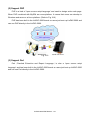
ICP DAS provides the library file - libi8k.a which includes all the functions from the
I-7000/8000/87000 series modules which are used in the LinPAC-5000 Embedded
Controller. The libi8k.a is designed specially for the high profile I-7000/8000/87000 series
modules on the Linux platform for use in the LinPAC-5000. Users can easily develop
applications in the LinPAC-5000 by using either C or Java Language and the .NET
applications will also be supported in the future. The various functions of the libi8k.a are
divided into the sub-group functions for ease of use within the different applications. The
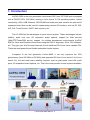
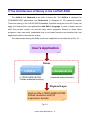
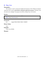
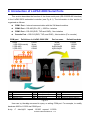
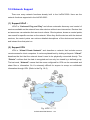
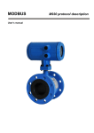
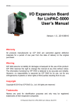
powerful functions of the LinPAC-5000 embedded controller are depicted in figure 1-1, which
includes a VGA, USB (Card Reader, Camera …), Mouse, Keyboard, microSD card,
Series ports (RS-232/485), Ethernet (Hub…), etc. in the picture. Presently, HTTP, FTP,
Telnet, SSH and SFTP Servers are built in and users can transfer files or use remote control
with the LinPAC-5000 more conveniently. In network communication, wireless, Bluetooth
transfer and Modem, GPRS, ADSL and Firewall are also supported. Fig. 1 illustrates
hardware architecture of the LinPAC-5000.
Fig. 1-1
LinPAC-5000 SDK Manual:6
2. Installation of LinPAC-5000 SDK
“LinPAC-5000 SDK” consists of the following major items.
z
LinPAC SDK library files
z
LinPAC SDK include files
z
Demo files
z
GNU ToolChain
From ftp://ftp.icpdas.com/pub/cd/linpac/napdos/lp-5000/ users can download the latest
version of LinPAC-5000 SDK. Then follows below steps to install the development toolkit
provided by ICP DAS for the application development of the LinPAC-5000 embedded
controller platform easily.
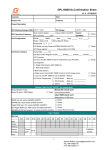
2.1 Quick Installation of LinPAC-5000 SDK
(1) Quick Installation Guide for Windows
1. Please insert the installation CD into your CD-ROM driver.
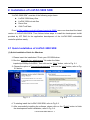
2. Run the “linpacsdk_for_windows.exe” file under the folder
\napdos\lp-5000\lp-5x3x\SDK\. Then click on the “Next” button, refer to Fig. 2-1.
3. Choose the option of “I accept the agreement” and click the “next” button, refer to Fig.
2-2 below.
Fig. 2 -1
Fig. 2-2
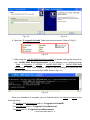
4. To starting install the LinPAC-5000 SDK, refer to Fig 2-3.
5. After successfully installing the software, please click on the “Finish” button to finish
the development toolkit installation, refer to Fig. 2-4.
LinPAC-5000 SDK Manual:7
Fig. 2-3
Fig. 2-4
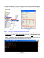
6. Open the “C:\cygwin\LinCon8k” folder and see the content. Refer to Fig 2-5.
Fig. 2-5
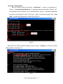
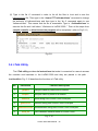
7. Start using the “LinPAC-5000 Build Environment” by double clicking the shortcut for
the “LinPAC-5000 Build Environment” on the desktop or by clicking through
“ Start ”>” Programs ”>” ICPDAS ”>” LinPAC-5000 SDK ”>”
LinPAC-5000 Build
Environment ” icon. Then a special DOSBOX will be displayed in which we can
compile applications for the LinPAC-5000. Refer to Fig. 2-6.
Fig. 2-6
Once your Installation is complete, you can find the files for the library and demo in the
following paths.
The Libi8k.a and libxwboard.a path is “C:\cygwin\LinCon8k\lib".
The include files path is “C:\cygwin\LinCon8k\include”
The demo path is “C:\cygwin\LinCon8k\examples”
LinPAC-5000 SDK Manual:8
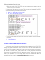
(2) Quick Installation Guide for Linux
1. Before you install LinPAC-5000 SDK, you must complete several tasks as the root
user by ‘sudo’ or ‘su’ command.
2. Download the “lp5k_sdk_for_linux.tar.bz2” file under the folder \napdos\lp-5xxx\SDK\.
3. Enter the following commands to extract the file:
$ bzip2
$
tar
-d
jxvf
lp5k_sdk_for_linux.tar.bz2
lp5k_sdk_for_linux.tar
4. To run the shell startup script and set the environment variables, enter the following
command:
$ . /lincon/linpac.sh
2.2 The LinPAC-5000 SDK Introduction
In this section, we will discuss some techniques that are adopted in the LinPAC-5000.
Through our detailed explanations, users can learn how to use the LinPAC-5000 easily.
LinPAC-5000 SDK is based on cygwin and it is also a Linux-like environment for Windows. It
still provides a powerful GCC cross-compiler and an IDE (Integrated Development
Environment) for developing LinPAC-5000 applications quickly. Therefore after you have
written your applications, you can compile them through the LinPAC-5000 SDK into
executable files that can be run in your LinPAC-5000 embedded controller.
LinPAC-5000 SDK Manual:9
2.2.1 Introduction to Cygwin
What is Cygwn ? Cygwin is a collection of free software tools originally developed by
Cygnus Solutions to allow various versions of Microsoft Windows to act somewhat like a
UNIX system. That is Cygwin is a Linux-like environment for Windows. It consists of two
parts:
(1) A DLL (cygwin1.dll) which acts as a Linux emulation layer providing substantial Linux API
functionality.
(2) A collection of tools, which provide users with the Linux look and feel.
2.2.2 Introduction to Cross-Compilation
What is Cross-Compilation? Generally, compiling a program takes place by running the
compiler on the build platform. The compiled program will run on the target platform. Usually
these two processes are on the same platform; if they are different, the process is called
cross-compilation. That is the process that can compile source code on one platform to the
executable files on other platforms. For example, you can compile source code in a x86
windows platform into an executable file that can run on an arm-linux platform if you use the
cross-compiler - “arm-linux-gcc”.
So why do we use Cross-Compilation? In fact, Cross-Compilation is sometimes more
involved and errors are easier to make than with normal compilation. Therefore it is often
only employed if the target is not able to compile programs on its own or when we want to
compile large programs that need more resources than the target can provide. For many
embedded systems, cross-compilation is the only possible way.
2.2.3 Download the LinPAC-5000 SDK
(1) For Windows system : (Extract the .exe file into to the C: driver.)
lp5k_sdk_for_windows.exe as below:
ftp://ftp.icpdas.com/pub/cd/linpac/napdos/lp-5000/lp-5x4x/sdk/lp5k_sdk_for_windows.exe
(2) For Linux system : (Extract the .bz2 file into to the root(/) directory.)
lp5k_sdk_for_linux.tar.bz2 as below:
ftp://ftp.icpdas.com/pub/cd/linpac/napdos/lp-5000/lp-5x4x/sdk/lp5k_sdk_for_linux.tar.bz2
LinPAC-5000 SDK Manual:10
3.The Architecture of library in the LinPAC-5000
The libi8k.a and libxboard.a are both a library file. The libi8k.a is designed for
I7000/8000/87000 applications and libxboard.a is designed for I/O expansion boards.
There are running in the LinPAC-5000 Embedded Controller using the Linux OS. Users can
apply it to develop their own applications with GNU C language. In order to assist users to
build their project quickly, we provide many demo programs. Based on these demo
programs, users can easily understand how to use these functions and develop their own
applications within a short period of time.
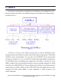
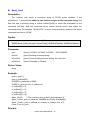
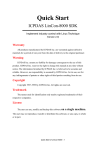
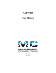
The relationships among the libi8k.a and user’s applications are depicted as Fig. 3-1:
User ’s Application
Driver
Libi8k.a
Libxwboard.a
( I-7000/I-8000/I-87000
Series modules function)
(xwboard series function)
Physical Layer
High profile I-7000/I-8000/I-87000
Series modules and I/O
expansion boards
Fig. 3-1
LinPAC-5000 SDK Manual:11
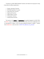
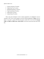
Functions for LinPAC-5000 Embedded Controller are divided into sub-groups for easy
of use within the different applications:
1.
System Information Functions
2.
EEPROM Read/Write Functions
3.
Watch Dog Timer Functions
4.
Digital Input Functions
5.
Digital Output Functions
6.
Analog Input Functions
7.
Analog Output Functions
The functions in the libi8k.a and libxwboard.a are specially designed for LinPAC-5000.
For libi8k.a usage, users can easily find the functions they need for their applications from
the descriptions in chapter 6 and in the demo programs provided in chapter 7. Another
driver-libxwboard.a, users can refer to LinPAC-5K_xwboard_user_guide.pdf.
LinPAC-5000 SDK Manual:12
4. LinPAC-5000 System Settings
In this section, we will introduce how to setup the LinPAC-5000 configuration. Let users
can use the LinPAC-5000 more easily.
4.1 Settings for the LinPAC-5000 Network
The LinPAC-5000 network setting includes two ways. One is DHCP and the other is
“Assigned IP”. DHCP is the default setting after the LinPAC-5000 is produced and this way
is easy for users. However, if your network system is without DHCP server, then users need
to configure the network setting by using “Assigned IP”.
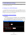
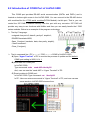
4.1.1 Setting the IP、Netmask and Gateway
(1) Using DHCP :
Boot up LinPAC-5000 and click the “start/xterm” to open a “command Prompt”.
Type in “vi /etc/network/interfaces” to open the network setting file. Remove “#” in
the dhcp block and add “#” in the Assign IP block. Then type “:wq” to save the
setting. Type “ifup eth0” to make the setting work. (Refer to the Fig 4-1)
Fig 4-1
LinPAC-5000 SDK Manual:13
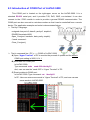
(2) Using “Assigned IP” :
Boot up LinPAC-5000 and click the “ start/xterm ” to open a “command line”.
Type in “ vi /etc/network/interfaces ” to open the network setting file. Remove “ # ”
in the Assign IP block and add “ # ” in the dhcp block. Type ip、netmask and gateway
you want in the Assign IP block. Then type “ :wq ” to save the setting. Type “ ifup
eth0 “ to make the setting work. (Refer to the Fig 4-2)
Fig 4-2
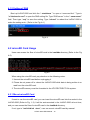
After finish the LinPAC network setting, users can type “ ifconfig “ to see the network
setting. (Refer to the Fig 4-3)
Fig 4-3
LinPAC-5000 SDK Manual:14
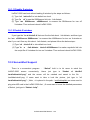
4.1.2 Setting of DNS
Boot up LinPAC-5000 and click the “ start/xterm ” to open a “command line”. Type in
“vi /etc/resolv.conf” to open the DNS setting file. Type “DNS server” in the “ nameserver”
field. Then type “:wq” to save the setting. Type “reboot” to reboot the LinPAC-5000 to
make the setting work. ( Refer to the Fig 4-4 )
Fig 4-4
4.2 microSD Card Usage
Users can access the files of microSD card in the /mnt/hda directory (Refer to the Fig
4-5).
Fig 4-5
When using the microSD card, pay attention to the following notes:
1. Umount the microSD card before unplugging it.
2. Please do not power off or reboot the LinPAC-5000 while data is being written to or
read from the microSD card.
3. The microSD memory must be formatted in the VFAT/EXT2/EXT3 file system.
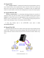
4.2.1 Mount microSD Card
If want to use the microSD card, you can insert the microSD card into the socket in the
LinPAC-5000 (Refer to Fig. 1-3). It will be auto-mounted in the LinPAC-5000 at boot time,
and you can access the files of microSD card in the /mnt/hda directory.
If not, type in “/etc/init.d/sd
start ”, user can mount microSD card by manual.
LinPAC-5000 SDK Manual:15
4.2.2 Umount microSD Card
Before you want to pull out the microSD card from the LinPAC-5000, please type the
following steps:
(1) /etc/init.d/apachect1
stop
(2) /etc/init.d/startx stop
(3) umount
/mnt/hda
Then you can pull out the microSD card safely to prevent the damage to microSD card.
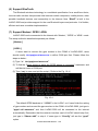
4.2.3 Scan and repair microSD Card
The microSD card at boot will be named “ /dev/mmcblk0p1 “. User could be umount
microSD card first before scan or repair microSD card.
blockdev : call block device ioctls from the command line
ex. blockdev
--report
/dev/mmcblk0p1
blockdev -v --getra --getbz /dev/mmcblk0p1
(print a report for device)
(get readhead and blocksize)
fsck.minix : perform a consistency check for the Linux MINIX filesystem
ex. fsck.minix -r
/dev/mmcblk0p1
(performs interactive repairs)
fsck.minix -s /dev/mmcblk0p1
(outputs super-block information)
fsck.vfat : check and repair MS-DOS file systems
ex. fsck.vfat
fsck.vfat
-a
/dev/mmcblk0p1
-l
(automatically repair the file system)
/dev/mmcblk0p1
(list path names of files being processed)
mkfs : build a Linux file system on a device, usually a hard disk partition.
ex. mkfs
-t vfat
/dev/mmcblk0p1
mkfs
-c vfat
/dev/mmcblk0p1
(specifies the type of file system to be built)
(check the device for bad blocks before building the file system)
mkfs.minix : make a MINIX filesystem
ex. mkfs.minix
mkfs.minix
/dev/mmcblk0p1
-c
(create a Linux MINIX file-system)
/dev/mmcblk0p1
(check the device for bad blocks before creating the file system)
mkfs.vfat : make an MS-DOS filesystem
ex. mkfs.vfat -A /dev/mmcblk0p1
mkfs.vfat -v /dev/mmcblk0p1
(use Atari variation of the MS-DOS filesystem)
(verbose execution)
LinPAC-5000 SDK Manual:16
4.3 USB Storage Device Usage
Users need to mount the USB storage device to the LinPAC-5000, before they can
access the USB storage device. This is because it will not auto-mount the USB storage
device in the LinPAC-5000
4.3.1 Mount USB Storage Device
The steps are as follows :
(1) Type “ mkdir
/mnt/usb “ to build a usb directory.
(2) Type “mount
/dev/sda1
directory and type “ ls
/mnt/usb“ to mount the USB storage device to the usb
/mnt/usb ” to see the content of USB storage device.
4.3.2 Umount USB Storage Device
Before users pull out the USB storage device from the LinPAC-5000, users need to
type the “ umount
/mnt/usb “ command first. Then pull out the USB storage device to
prevent any damage to usb storage device.
4.4 Adjust VGA Resolution
There are two modes -- 640x480、800x600 supported in the LinPAC VGA resolution and
the default setting is 800x600. If users want to change the VGA resolution. Please follow
below steps :
(1) Type “ vi /etc/init.d/fbman “ to open resolution setting file.
(2) If users want to set the resolution to be 640x480. First, add “ # ” in the 800x600
column and then remove “ # ” in the 640x480 column. Type “ :wq “ to save the
setting. (Refer to Fig 4-6)
(3) Type “ reboot “ to reboot LinPAC-5000.
Note: This function can not support LinPAC-53x1.
LinPAC-5000 SDK Manual:17
Fig 4-6
4.5 Running applications automatically at boot time
A “run level” determines which programs are executed at system startup. Run level 2 is
the default run level of LinPAC-5000.
The contents of run level are in the /etc/init.d directory that directory contains the scripts
executed at boot time. These scripts are referenced by symbolic links in the /etc/rc2.d.
These links are named S<2-digit-number><original-name>. The numbers determine the
order in which the scripts are run, from 00 to 99 — the lower number would earlier executed.
Scripts named with an S are called with start, and named with a K or x are called with stop.
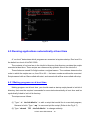
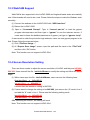
4.5.1 Making program run at boot time
Making program run at boot time, you should create a startup script placed in /etc/init.d
directory that runs the required commands for executed automatically at boot time and be
symbolically linked to /etc/rc2.d directory.
The steps are as follows :
(1) Type “ vi
/etc/init.d/hello “ to edit a script that would like to executed program,
filename is hello. Type “ :wq “ to save and quit the script. (Refer to the Fig 4-7)
(2) Type “ chmod
755
/etc/init.d/hello “ to change authority.
LinPAC-5000 SDK Manual:18
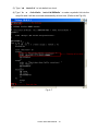
(3) Type “ cd
(4) Type ” ln
/etc/rc2.d “ to into default run level.
-s ../init.d/hello
/etc/rc2.d/S85hello “ to make a symbolic link into the
script file and it will be executed automatically at boot time. (Refer to the Fig 4-8)
Fig. 4-7
LinPAC-5000 SDK Manual:19
Fig. 4-8
4.5.2 Disabling program run at boot time
The steps are as follows :
(1) Type “ cd
/etc/rc2.d “ to into default run level.
(2) Type “ mv
S85hello
xS85hello “ to rename the S85hello symbolic link for turn off
running program automatically at boot time.
LinPAC-5000 SDK Manual:20
4.6 Automatic login
Log the specified user onto the console (normally /dev/tty1) when the system is first
booted without prompting for a username or password using mingetty command.
The steps are as follows :
(1) Login as root and edit /etc/inittab
(2) Modify the entry for the first terminal― tty1
Below user can see the modified part of LinPAC-5000 /etc/inittab file (Refer to the Fig
4-9), and it will autologins into the root account after reboot the LinPAC-5000.
Fig. 4-9
LinPAC-5000 SDK Manual:21
5. Instructions for the LinPAC-5000
In this section, some Linux instructions that are often used will be introduced. The use of
these instructions in linux is very familiar with those in DOS and generally they are used in
lower case.
5.1 Basic Linux Instructions
5.1.1
ls : list the file information -> ( like dir in DOS )
Parameter:
(1) -l:list detailed information of file
( Example:ls -l )
(2) -a:list all files including hidden files
( Example:ls -a )
(3) -t:list the files that are arranged by time(from new to old)
5.1.2
cd directory : Change directory -> ( like cd in DOS )
Parameter:
(1) ..:move to the upper directory
( Example:cd .. )
(2) ~:move back to the root directory
(3) /:divided sign
( Example:cd ~ )
(for examples:cd /root/i8k )
5.1.3
mkdir:create the subdirectory -> ( like md in DOS )
mkdir
–parameter
subdirectory
( Example:mkdir owner )
5.1.4
rmdir:delete(remove) the subdirectory and it must be empty ->
( like rd in DOS )
rmdir
–parameter
subdirectory
( Example:rmdir owner )
5.1.5
rm : delete file or directory -> ( like del or deltree in DOS )
LinPAC-5000 SDK Manual:22
rm
–parameter
file ( or directory )
Parameter:
(1) i:it will show the warning message when deleting ( Example:rm -i test.exe )
(2) r:delete directory despite that it isn’t empty ( Example:rm –r Test )
(3) f:it will not show a warning message when deleting ( Example:rm -f test.exe )
5.1.6
cp
cp:copy file -> ( like copy in DOS )
–parameter
( Example:cp
5.1.7
mv
source file
destination file
test.exe /root/Test/test.exe )
mv:move or rename file or directory -> ( like move or ren in DOS )
–parameter
source file ( or directory )
( Example:mv
test.exe test1.exe )
( Example:mv
test.exe /root/Test )
5.1.8
pwd:show the current path
5.1.9
who:show the on-line users
5.1.10
chmod:change authority of file
chmod
???
destination file ( or directory )
file -> ??? means owner:group:all users
For example:
chmod
754
test.exe
7 5 4 -> 111(read, write, execute)
101(read, write, execute) 100(read, write,
execute)
The first number 7 :owner can read and write and execute files
The second number 5:group can only read and execute files
The third number 4
5.1.11
:all users can only read files
uname:show the version of linux
LinPAC-5000 SDK Manual:23
5.1.12
ps:show the procedures that execute now
5.1.13
ftp:transfer file
ftp IPAdress ( Example:ftp 192.168.0.200 -> connet to ftp server )
!:exit FTP back to pc temporarily;exit:back to ftp
bin:transfer files in “binary” mode
get:download file from LinPAC to PC ( Ex:get /mnt/hda/test.exe c:/test.exe )
put:upload file from PC to LinPAC ( Ex:put
c:/test.exe
/mnt/hda/test.exe )
bye:exit FTP
5.1.14
telnet:connect to other PC
telnet IPAddress (Example:telnet 192.168.0.200->remote control LinPAC-5000 )
5.1.15
date:show date and time
5.1.16
netstat:show the state of network
Parameter [ -a ]:list all states
( Example:netstat -a )
5.1.17
ifconfig:show the ip and network mask ( like ipconfig in DOS )
5.1.18
ping:check to see if the host in the network is alive
ping IPAddress ( Example:ping 192.168.0.1 )
5.1.19
clear:clear the screen
5.1.20
passwd:change the password
5.1.21
reboot:reboot the LinPAC
LinPAC-5000 SDK Manual:24
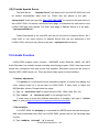
5.2 General GCC Instructions
GCC is a cross-compiler provided by GNU and it can compile source code written by
ANSI C or by Tranditional C into executable files. The executable file compiled by GCC can
run in different OSs and in different Hardware systems. Therefore GCC is very popular
within the Unix system which is a large part of why its popularity is growing so well.
Furthermore it is free, and therefore can be downloaded via your network with ease.
First, Fig. 5-1 illustrates the compilation procedure within Linux:
Fig. 5-1
Second, we will list some GCC instructions to let users compile *.c to *.exe smoothly and
to explain the parameters for GCC in its compilation process.
LinPAC-5000 SDK Manual:25
5.2.1 Compile without linking the LinPAC-5000 library
(1) Purpose:*. c
to
*. exe
Command:arm-linux-gcc
–o
target
source.c
Parameter:
-o target:assign the name of output file
source.c:source code of C
Example:arm-linux-gcc
–o
helloworld.exe
helloworld.c
Output File:helloworld.exe
5.2.2 Compile with linking the LinPAC-5000 library ( libi8k.a )
(1) Purpose:*. c
to
*. o
Command:arm-linux-gcc
–IincludeDIR -lm
–c
–o
target
source.c
library
Parameter:
-IincludeDir:the path of include files
-lm:include math library ( libm.a )
-c:just compile *.c to *.o ( object file )
-o target:assign the name of output file
source.c:source code of C
library:the path of library
Example:arm-linux-gcc –I. –I../include –lm –c –o test.o test.c ../lib/libi8k.a
Output File:test.o
(2) Purpose:*. o
to
*. exe
Command:arm-linux-gcc
–IincludeDIR
-lm
–o
target
Parameter:
-IincludeDir:the path of include files
-lm:include math library ( libm.a )
LinPAC-5000 SDK Manual:26
source.o
library
-o target:assign the name of output file
source.o:object file
library:the path of library
Example:arm-linux-gcc –I. –I../include –lm –o test.exe test.o ../lib/libi8k.a
Output File:test.exe
(3) Purpose:*. c
to
*. exe
Command:arm-linux-gcc
–IincludeDIR -lm
–o
target
source.c
library
Parameter:
-IincludeDir:the path of include files
-lm:include math library ( libm.a )
-o
target:assign the name of output file
source.c:source code of C
library:the path of library
Example:arm-linux-gcc –I. –I../include –lm –o test.exe test.c ../lib/libi8k.a
Output File:test.exe
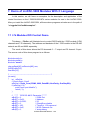
5.3 A Simple Example – Helloworld.c
In this section, we will introduce how to compile the helloworld.c to helloworld.exe and
transfer the helloworld.exe to the LinPAC-5000 by using FTP. Finally executes this file via
the Telnet Server on the LinPAC-5000. These steps can be accomplished in one pc without
another monitor for the LinPAC-5000. In this example, no ICP DAS modules are used. If you
want to use the modules of ICP DAS to control your system, you can refer to demo in the
chapter 7.
These processes can be divided into three steps and thet are given as below:
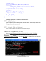
STEP 1 :( Compile helloworld.c to helloworld.exe )
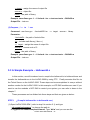
(1) Open LinPAC-5000 SDK ( refer to step 8 in section 2.1) and type
“ cd examples/common ” to change the path to
C:/cygwin/LinCon8k/examples/common. Type “dir/w” and you can see the
LinPAC-5000 SDK Manual:27
helloworld.c file. (refer to Fig.5-2)
Fig. 5-2
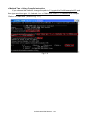
(2) Type in “arm-linux-gcc –o helloworld.exe helloworld.c“ to compile helloworld.c into
helloworld.exe. Then type “dir/w“ to see the helloworld.exe file. (refer to Fig.5-3)
LinPAC-5000 SDK Manual:28
Fig. 5-3
STEP 2 :( Transfer helloworld.exe to the LinPAC-5000 )
There are two methods for transferring files to the LinPAC-5000:
< Method one > By Using the “DOS Command Prompt”:
(1) Open a “DOS Command Prompt” and type in the ftp IPAddress of the LinPAC-5000
( Example:ftp 192.168.0.200) to connect to the FTP Server on the LinPAC-5000. Then
type the User_Name and Password ( “ root ” is the default value. )
to accomplish the
connection from the PC to the LinPAC-5000.
(2) Before transferring your files to the LinPAC-5000, type in the “bin” command to make the
file transfer to the LinPAC-5000 in binary mode. (refer to Fig.5-4)
Fig.5-4
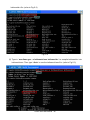
(3) Type in “ put
C:/cygwin/LinCon8k/examples/common/helloworld.exe
helloworld.exe ” to transfer helloworld.exe to the LinPAC-5000. If it shows the message
of “ Transfer complete ”, then the whole transferring process has been accomplished. If
you need to disconnect from the LinPAC-5000, type in the “ bye ” command to return to
the PC console. (refer to Fig.5-5).
LinPAC-5000 SDK Manual:29
Fig.5-5
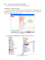
< Method two > By Using FTP Software:
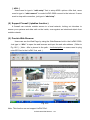
(1) Open the FTP Software and add a ftp site to the LinPAC-5000. The User_Name and
Password default value is “root”. Then click the “Connect” button to connect to the ftp
server of the LinPAC-5000. (refer to Fig.5-6).
Fig.5-6
(2) Upload the file - Helloworld.exe to the LinPAC-5000. (refer to Fig.5-7).
Fig.5-7
LinPAC-5000 SDK Manual:30
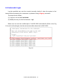
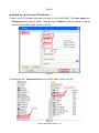
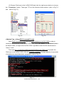
(3) Choose helloworld.exe in the LinPAC-5000 and click the right button of mouse to choose
the “ Permissions ” option. Then type 777 into the Numeric textbox. (refer to Fig.5-8
and Fig.5-9 ).
Fig.5-8
Fig.5-9
STEP 3 :( Telnet to the LinPAC-5000 and execute program)
(1) Open a “ DOS Command Prompt ” and then type in the telnet IPAddress of the
LinPAC-5000 ( Example:telnet 192.168.0.200 ) to connect to the telnet server of the
LinPAC-5000. Then type the User_Name and Password (“ root ” is the default
value. ). If it shows the “ # “ prompt character, the process of connecting from your PC to
the telnet server of the LinPAC-5000 is finished. (refer to Fig.5-10)
Fig.5-10
LinPAC-5000 SDK Manual:31
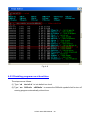
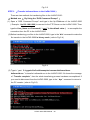
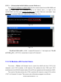
(2) Type in the “ls -l“ command in order to list all the files in /root and to see the
helloworld.exe file. Then type in the “chmod 777 helloworld.exe” command to change
the authority of helloworld.exe and then type in the “ls -l“ command again to see
“helloworld.exe”. This means that the file is executable. Type in “./helloworld.exe“ to
execute the file and it will show “ Welcome to LinPAC-5000 ”. Then all the steps from
compile, transfer to telnet to execute program will be completed. (refer to Fig.5-11)
Fig.5-11
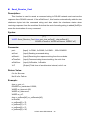
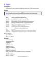
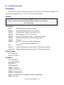
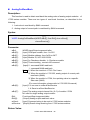
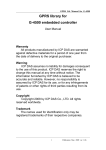
5.4 i-Talk Utility
The i-Talk utility provides six instructions that make it convenient for users to access
the modules and hardware in the LinPAC-5000 and they are placed in the path -
/usr/local/bin. Fig. 5-12 describes the functions of i-Talk utility.
No.
Instruction
Function Description
1
getport
Get port value by offset from a module
2
setport
Set port value by offset to a module
3
setsend
Send string from LinPAC-5000 COM port
4
getreceive
5
getsendreceive
6
read_sn
Receive string from LinPAC-5000 COM port
Send/Receive string from LinPAC-5000 COM port
Get Hardware Serial Number of LinPAC-5000
Fig. 5-12
LinPAC-5000 SDK Manual:32
Users can also type in the instructions name and it will show the instructions usage.
LinPAC-5000 SDK Manual:33
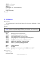
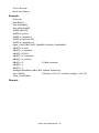
6. LIBI8K.A
In this section, we will focus on examples for the description of and application of the
functions found in the Libi8k.a. The Libi8k.a functions can be clarified into 3 groups which
are listed in Fig. 6-1.
Fig. 6-1
Functions (1) and (2) in the Libi8k.a are the same as with the DCON.DLL Driver
(including Uart.dll and I7000.dll) as used in the DCON modules (High profile I-7000/I-8000
/I-87000 in serial communication). You can refer to the DCON.DLL Driver manual which
includes the functions on how to use DCON modules (http://www.icpdas.com/products/).
The DCON.DLL Driver has already been wrapped into the Libi8k.a. Functions (3) of the
Libi8k.a consist of the most important functions as they are specially designed for I-8000
modules in the LinPAC-5000 slots. They are different from functions (1) and (2) because the
communication of I-8000 modules in the LinPAC-5000 slots are parallel and not serial.
Therefore ICP DAS rewrote I8000.c to Slot.c especially for I-8000 modules in the
LinPAC-5000 slots.
Here we will introduce all the funcitions for slot.c and they can be divided into night
LinPAC-5000 SDK Manual:34
parts for ease of use.
1.
System Information Functions;
2.
Watch Dog Timer Functions;
3.
EEPROM Read/Write Functions;
4.
Digital Input/Output Functions;
5.
Analog Input Functions;
6.
Analog Output Functions;
When using the development tools to develop applications, the msw.h file must be
included in front of the source program, and when building applications, libi8k.a must be
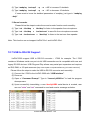
linked. If you want to control ICP DAS I/O remote modules like i7k, i8k and i87k through
COM1 or COM2 or COM3 of the LinPAC-5000, the functions are all the same with DCON
DLL.
LinPAC-5000 SDK Manual:35
6.1 System Information Functions
Open_Slot
Description:
This function is used to open and initiate a specifed slot in the LinPAC-5000. The I/O
expansion board(http://www.icpdas.com/products/PAC/up-5000/XW-board_Selection_Guide.htm) in the
LinPAC-5000 will use this function. For example, if you want to send or receive data from a
specified slot, this function must be called first. Then the other functions can be used later.
Syntax:
[C]
int Open_Slot(int slot)
Parameter:
slot :
[Input] Specify the slot number in which the I/O module is plugged into.
(Range of slot: 0~1)
Return Value:
0 is for Success
Not 0 is for Failure
Example:
Int slot=1;
Open_Slot(slot);
// The first slot in the LinPAC-5000 will be open and initiated, and only for XW-board.
Remark:
LinPAC-5000 SDK Manual:36
Close_Slot
Description:
If you have used the function of Open_Slot() to open the specifed slot in the
LinPAC-5000, you need to use the Close_Slot() function to close the specifed slot in the
LinPAC-5000. The The I/O expansion board in the LinPAC-5000 will use this function. For
example, once you have finished sending or receiving data from a specified slot, this
function would then need to be called.
Syntax:
[C]
void Close_Slot(int slot)
Parameter:
slot :
[Input] Specify the slot number in which the I/O module is plugged into.
(Range of slot: 0~1)
Return Value:
None
Example:
int slot=1;
Close_Slot(slot);
// The first slot in the LinPAC-5000 will be closed, and only for XW-board.
Remark:
LinPAC-5000 SDK Manual:37
Open_SlotAll
Description:
This function is used to open and initiate all slots in the LinPAC-5000. For example, if
you want to send or receive data from multiple slots, you can call this function to simplify
your program. Then you can use the other functions later.
Syntax:
[C]
int Open_SlotAll(void)
Parameter:
None
Return Value:
0 is for Success
Not 0 is for Failure
Example:
Open_SlotAll();
// All slots in the LinPAC-5000 will be open and initiated.
Remark:
LinPAC-5000 SDK Manual:38
Close_SlotAll
Description:
If you have used the function Open_SlotAll() to open all the slots in the LinPAC-5000,
you can use the Close_SlotAll() function to close all the slots in the LinPAC-5000. For
example, once you are finish sending or receiving data from many slots, this function can be
called to close all the slots rapidly.
Syntax:
[C]
void Close_SlotAll(void)
Parameter:
None
Return Value:
None
Example:
Close_SlotAll();
// All slots in the LinPAC-5000 will be closed.
Remark:
LinPAC-5000 SDK Manual:39
Open_Com
Description:
This function is used to configure and open the COM port. It must be called once
before sending/receiving command through COM port. For example, if you want to send or
receive data from a specified COM port, you need to call this function first. Then you can use
the other series functions.
Syntax:
[C]
WORD Open_Com(char port, DWORD baudrate, char cData, char cParity, char cStop)
Parameter:
port :
[Input] COM1, COM2, COM3..., COM255.
baudrate:
[Input] 1200/2400/4800/9600/19200/38400/57600/115200
cDate :
[Input] Data5Bit, Data6Bit, Dat7Bit, Data8Bit
cParity :
[Input] NonParity, OddParity, EvenParity
cStop :
[Input] OneStopBit, TwoStopBit
Return Value:
0 is for Success
Not 0 is for Failure
Example:
Open_Com(COM3, 9600, Data8Bit, NonParity, OneStopBit);
Remark:
LinPAC-5000 SDK Manual:40
Close_Com
Description:
This function is used to closes and releases the resources of the COM port computer
rescourse. And it must be called before exiting the application program. The Open_Com
will return error message if the program exit without calling Close_Com function.
Syntax:
[C]
BOOL Close_Com(char port)
Parameter:
port :
[Input] COM1,COM2, COM3...COM255.
Return Value:
None
Example:
Close_Com (COM3);
Remark:
LinPAC-5000 SDK Manual:41
Send_Receive_Cmd
Description:
This function is used to sends a command string to RS-485 network and receives the
response from RS-485 network. If the wChkSum=1, this function automatically adds the two
checksum bytes into the command string and also check the checksum status when
receiving response from the modules. Note that the end of sending string is added [0x0D] to
mean the termination of every command.
Syntax:
[C]
WORD Send_Receive_Cmd (char port, char szCmd[ ], char szResult[ ],
WORD wTimeOut, WORD wChksum, WORD *wT)
Parameter:
port :
[Input] 1=COM1, 2=COM2, 3=COM3..., 255=COM255.
szCmd:
[Input] Sending command string
szResult :
[Input] Receiving the response string from the modules
wTimeOut ::
[Input] Communicating timeout setting, the unit=1ms
wChkSum ::
[Input] 0=Disable, 1=Enable
*wT:
[Output] Total time of send/receive interval, unit=1 ms
Return Value:
0 is for Success
Not 0 is for Failure
Example:
char m_port =1;
DWORD m_baudrate=115200;
WORD m_timeout=100;
WORD m_chksum=0;
WORD m_wT;
char m_szSend[40], m_szReceive[40];
int RetVal;
m_szSend[0] = '$';
m_szSend[1] = '0';
m_szSend[2] = '0';
m_szSend[3] = 'M';
LinPAC-5000 SDK Manual:42
m_szSend[4] = 0;
/* open device file */
Open_Slot(1);
RetValue = Open_Com(m_port, m_baudrate, Data8Bit, NonParity, OneStopBit);
if (RetValue >0)
{
printf("Open COM%d failed!\n", m_port);
return FAILURE;
}
RetValue = Send_Receive_Cmd(m_port, m_szSend, m_szReceive, m_timeout,
m_chksum, &m_wT);
if (RetValue)
{
printf("Module at COM%d Address %d error !!!\n", m_port, m_szSend[2] );
return FAILURE;
}
Close_Com (m_port);
LinPAC-5000 SDK Manual:43
Send_Cmd
Description:
This function only sends a command string to DCON series modules. If the
wChkSum=1, it automatically adds the two checksum bytes to the command string. And
then the end of sending string is further added [0x0D] to mean the termination of the
command (szCmd). And this command string cannot include space char within the
command string. For example: “$01M 02 03” is user’s command string. However, the actual
command send out is “$01M”.
Syntax:
[C]
WORD Send_Cmd (char port, char szCmd[ ], WORD wTimeOut, WORD wChksum)
Parameter:
port :
:
[Input] 1=COM1, 2=COM2, 3=COM3..., 255=COM255.
szCmd :
[Input] Sending command string
wTimeOut :
[Input] Communicating timeout setting, the unit=1ms
wChkSum :
[Input] 0=Disable, 1=Enable
Return Value:
None
Example:
char m_port=1;
char m_szSend[40] ;
DWORD m_baudrate=115200;
WORD m_timeout=100, m_chksum=0;
m_szSend[0] = '$';
m_szSend[1] = '0';
m_szSend[2] = '0';
m_szSend[3] = 'M';
Open_Slot(2);
// The module is plug in slot 2 and address is 0.
Open_Com(m_port, m_baudrate, Data8Bit, NonParity, OneStopBit);
Send _Cmd(m_port, m_szSend, m_timeout, m_chksum, &m_wT);
Close_Com (m_port);
Remark:
LinPAC-5000 SDK Manual:44
Receive_Cmd
Description:
This function is used to obtain the responses string from the modules in RS-485
network. And this function provides a response string without the last byte [0x0D].
Syntax:
[C]
WORD Receive_Cmd (char port, char szResult[ ], WORD wTimeOut,
WORD wChksum)
Parameter:
port :
:
[Input] 1=COM1, 2=COM2, 3=COM3..., 255=COM255.
szResult : :
[Output] Sending command string
wTimeOut :
[Input] Communicating timeout setting, the unit=1ms
wChkSum :
[Input] 0=Disable, 1=Enable
Return Value:
None
Example:
char m_port=3;
char m_Send[40], m_szResult[40] ;
DWORD m_baudrate=115200;
WORD m_timeout=100, m_chksum=0;
m_szSend[0] = '$';
m_szSend[1] = '0';
m_szSend[2] = '1';
m_szSend[3] = 'M';
m_szSend[4] = 0;
Open_Com (m_port, m_baudrate, Data8Bit, NonParity, OneStopBit);
Send _Cmd (m_port, m_szSend, m_timeout, m_chksum);
Receive_Cmd (m_port, m_szResult, m_timeout, m_chksum);
Close_Com (m_port);
// Read the remote module:I-7016D , m_ szResult : “!017016D”
Remark:
LinPAC-5000 SDK Manual:45
Send_Binary
Description:
Send out the command string by fix length, which is controlled by the parameter “iLen”.
The difference between this function and Send_cmd is that Send_Binary terminates the
sending process by the string length “iLen” instead of the character "CR"(Carry return).
Therefore, this function can send out command string with or without null character under
the consideration of the command length. Besides, because of this function without any error
checking mechanism (Checksum, CRC, LRC... etc.), users have to add the error checking
information to the raw data by themselves if communication checking system is required.
Note that this function is usually applied to communicate with the other device, but not for
ICP DAS DCON (I-7000/8000/87K) series modules.
Syntax:
[C]
WORD Send_Binary (char port, char szCmd[ ], int iLen)
Parameter:
port :
:
[Input] 1=COM1, 2=COM2, 3=COM3..., 255=COM255.
szCmd :
[Input] Sending command string
iLen :
[Input] The length of command string.
Return Value:
None
Example:
int m_length=4;
char m_port=3, char m_szSend[40];
DWORD m_baudrate=115200;
m_szSend[0] = '0';
m_szSend[1] = '1';
m_szSend[2] = '2';
m_szSend[3] = '3';
Open_Com(m_port, m_baudrate, Data8Bit, NonParity, OneStopBit);
Send _Binary(m_port, m_szSend, m_length);
Close_Com (m_port);
Remark:
LinPAC-5000 SDK Manual:46
Receive_Binary
Description:
This function is applied to receive the fix length response. The length of the receiving
response is controlled by the parameter “iLen”. The difference between this function and
Receive_cmd is that Receive_Binary terminates the receiving process by the string length
“iLen” instead of the character "CR"(Carry return). Therefore, this function can be used to
receive the response string data with or without null character under the consideration of
receiving length. Besides, because of this function without any error checking mechanism
(checksum, CRC, LRC... etc.), users have to remove from the error checking information
from the raw data by themselves if communication checking system is used. Note that this
function is usually applied to communicate with the other device, but not for ICP DAS DCON
(I-7000/8000/87K) series modules.
Syntax:
[C]
WORD Receive_Binary (char cPort, char szResult[], WORD wTimeOut,
WORD wLen, WORD *wT)
Parameter:
port :
:
[Input] 1=COM1, 2=COM2, 3=COM3..., 255=COM255.
szResult :
[Input] Receiving the response string from the modules
wTimeOut ::
[Input] Communicating timeout setting, the unit=1ms
wLen :
[Input] The length of command string.
*wT:
[Output] Total time of send/receive interval, unit=1 ms
Return Value:
None
Example:
int m_length=10;
char m_port=3;
char m_szSend[40];
char m_szReceive[40];
DWORD m_baudrate=115200;
WORD m_wt;
WORD m_timeout=10;
LinPAC-5000 SDK Manual:47
WORD m_wlength=10;
m_szSend[0] = '0';
m_szSend[1] = '1';
m_szSend[2] = '2';
m_szSend[3] = '3';
m_szSend[4] = '4';
m_szSend[5] = '5';
m_szSend[6] = '6';
m_szSend[7] = '7';
m_szSend[8] = '8';
m_szSend[9] = '9';
Open_Com(m_port, m_baudrate, Data8Bit, NonParity, OneStopBit);
Send _Binary(m_port, m_szSend, m_length);
// send 10 character
Receive_Binary(char m_port, char m_szResult[], WORD m_timeout,
WORD m_wlength, WORD &m_wt)
// receive 10 character
Close_Com (m_port);
Remark:
LinPAC-5000 SDK Manual:48
sio_open
Description:
This function is used to open and initiate a specifed serial port in the LinPAC-5000. The
n-port modules in the LinPAC-5000 will use this function. For example, if you want to send or
receive data from a specified serial port, this function must be called first. Then the other
functions can be used later.
Syntax:
[C]
int sio_open(const char *port, speed_t baudrate, tcflag_t data, tcflag_t parity,
tcflag_t stop)
Parameter:
port :
[Input] device name: /dev/ttyS0, /dev/ttyS1…/dev/ttyS34
baudrate:
[Input] B1200/ B2400/ B4800/ B9600/ B19200/ B38400/ B57600/
B115200
date :
:
[Input] DATA_BITS_5/ DATA_BITS_6/ DATA_BITS_7/ DATA_BITS_8
parity :
:
[Input] NO_PARITY / ODD_PARITY / EVEN_PARITY
stop :
:
[Input] ONE_STOP_BIT / TWO_STOP_BITS
Return Value:
This function returns int port descriptor for the port opened successfully.
ERR_PORT_OPEN is for Failure
Example:
#define COM_M1 "/dev/ttyS0"
// Defined the first port for COM2(RS-485)
char fd[5];
fd[0]=sio_open(COM_M1, B9600, DATA_BITS_8, NO_PARITY,ONE_STOP_BIT);
if (fd[0] == ERR_PORT_OPEN) {
printf("open port_m failed!\n");
return (-1);
}
// The first port will be opened.
Remark:
LinPAC-5000 SDK Manual:49
sio_close
Description:
If you have used the function of sio_open() to open the specifed serial port in the
LinPAC-5000, you need to use the sio_close() function to close the specifed serial port in the
LinPAC-5000. For example, once you have finished sending or receiving data from a
specified serial port, this function would then need to be called.
Syntax:
[C]
int sio_close(int port)
Parameter:
port :
[Input] device name: /dev/ttyS0, /dev/ttyS1…/dev/ttyS34
Return Value:
None
Example:
#define COM_M2 "/dev/ttyS1"
// Defined the second port for COM3(RS-232)
char fd[5];
fd[0]=sio_open(COM_M2, B9600, DATA_BITS_8, NO_PARITY,ONE_STOP_BIT);
sio_close (fd[0]);
// The second port will be closed.
Remark:
LinPAC-5000 SDK Manual:50
sio_set_noncan
Description:
If you have used the function of sio_open() to open the specifed serial port in the
LinPAC-5000, you need to use the sio_close() function to close the specifed serial port in the
LinPAC-5000. For example, once you have finished sending or receiving data from a
specified serial port, this function would then need to be called.
set a opened serial port to non-canonical mode
Syntax:
[C]
int sio_set_noncan (int port)
Parameter:
port :
[Input] device name: /dev/ttyS0, /dev/ttyS1…/dev/ttyS34
Return Value:
None
Example:
#define COM_M2 "/dev/ttyS1"
// Defined the second port for COM3(RS-232)
char fd[5];
fd[0]=sio_open(COM_M2, B9600, DATA_BITS_8, NO_PARITY,ONE_STOP_BIT);
sio_close (fd[0]);
// The second port will be closed.
Remark:
LinPAC-5000 SDK Manual:51
Read_SN
Description:
This function is used to retrieves the hardware serial identification number on the
LinPAC-5000 main controller. This function supports the control of hardware versions by
reading the serial ID chip
Syntax:
[C]
void Read_SN(unsigned char serial_num[])
Parameter:
serial_num : [Output] Receive the serial ID number.
Return Value:
None
Example:
int slot ;
unsigned char serial_num[8];
Open_Slot(0);
Read_SN(serial_num);
printf("SN=%x%x%x%x%x%x%x%x\n",serial_num[0],serial_num[1], serial_ num[2]
,serial_num[3],serial_num[4],serial_num[5],serial_num[6],serial_num[7]);
Remark:
LinPAC-5000 SDK Manual:52
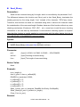
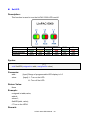
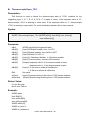
SetLED
Description:
This function is used to turn the LinPAC-5000 LED’s on/off.
Address
Color
Programmable
Function
L4
Green
Yes
None
L3
Yellow
Yes
None
L2
Green
Yes
None
RUN/L5
Red
Yes
Start
PWR
Green
No
Power
Syntax:
[C]
void SetLED(unsigned int addr, unsigned int value)
Parameter:
addr :
[Input] Range of programmable LED display is1~5
value :
[Input] 1 : Turn on the LED
0 : Turn off the LED
Return Value:
None
Example:
unsigned int addr,value;
addr=4;
value=1;
SetLED(addr, value);
// Turn on the LED4.
Remark:
LinPAC-5000 SDK Manual:53
L1
Red
Yes
None
GetBackPlaneID
Description:
This function is used to retrieve the back plane ID number in the LinPAC-5000.
Syntax:
[C]
int GetBackPlaneID()
Parameter:
None
Return Value:
Backplane ID number.
Example:
int id;
id=GetBackPlaneID();
printf("GetBackPlanel =%d \n", id);
// Get the LinPAC-5000 backplane id . Returned Value: GetBackPlanel = 2
Remark:
LinPAC-5000 SDK Manual:54
GetRotaryID
Description:
This function is used to retrieve the rotary ID number in the LinPAC-5000.
Syntax:
[C]
int GetRotaryID(int type, &id)
Parameter:
slot :
[input]
number of slot.
id:
[Output] Rotary ID mumber
Return Value:
0 is for Success
Not 0 is for Failure
Example:
int id, slot, type, wRetVal;
switch(type){
case 1:
slot = 0;
break;
case 2:
//Only for LinPAC-5000
slot = 8;
break;
default:
slot = 0;
break;
}
wRetVal = Open_Slot(slot);
if (wRetVal > 0) {
printf("open Slot%d failed!\n",slot);
return (-1);
}
id= GetRotaryID(type, &id);
printf("GetRotaryID =%d \n",id); // Get the LinPAC-5000 rotary id. If user turn the rotary
switch to the 1 position, would get the returned value: GetRotaryID = 78
Remark:
LinPAC-5000 SDK Manual:55
GetSDKversion
Description:
This function is used to retrieve the version of LinPAC-5000 SDK.
Syntax:
[C]
float GetSDKversion(void)
Parameter:
None
Return Value:
Version number.
Example:
printf(" GetSDKversion = %4.2f \n ", GetSDKversion());
// Get the LinPAC-5000 SDK version number.
// Returned Value: GetSDKversion = 1.0
Remark:
LinPAC-5000 SDK Manual:56
6.2 Watch Dog Timer Functions
EnableWDT
DisableWDT
Description:
This function can be used to enable the watch dog timer (WDT) and users need to reset
WDT in the assigned time set by users. Or LinPAC will reset automatically.
Syntax:
[C]
void EnableWDT(unsigned int msecond)
void DisableWDT(void)
Parameter:
msecond:
LinPAC will reset in the assigned time if users don’t reset WDT.
The unit is mini-second.
Return Value:
None
Example:
EnableWDT(10000); //Enable WDT interval 10000ms=10s
while (getchar()==10)
{
printf("Refresh WDT\n");
EnableWDT(10000); //Refresh WDT 10s
}
printf("Disable WDT\n");
DisableWDT();
Remark:
LinPAC-5000 SDK Manual:57
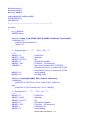
WatchDogSWEven
Description:
This function is used to read the LinPAC Reset Condition and users can reinstall the
initial value according to the Reset Condition.
Syntax:
[C]
unsigned int WatchDogSWEven (void)
Parameter:
None
Return Value:
Just see the last number of the return value – RCSR ( Reset Controller Status Register).
For example : RCSR is “20009a4”, so just see the last number “4”. 4 is 0100 in bits and it
means :
Bit 0 : Hardware Reset ( Like : Power Off, Reset Button )
Bit 1 : Software Reset ( Like : Type “Reboot” in command prompt )
Bit 2 : WDT Reset ( Like : Use “EnableWDT(1000)” )
Bit 3 : Sleep Mode Reset ( Not supported in the LinPAC )
Example:
printf("RCRS = %x\n", WatchDogSWEven() );
Remark:
LinPAC-5000 SDK Manual:58
ClearWDTSWEven
Description:
This function is used to clear RCSR value.
Syntax:
[C]
void ClearWDTSWEven (unsigned int rcsr)
Parameter:
rcsr :
Clear bits of RCSR. Refer to the following parameter setting:
1 : clear bit 0
2 : clear bit 1
4 : clear bit 2
8 : clear bit 3
F : clear bit 0 ~ bit 3
Return Value:
None
Example:
ClearWDTSWEven(0xF) ; // Used to clear bit 0 ~ bit 3 of RCRS to be zero.
Remark:
LinPAC-5000 SDK Manual:59
6.3 EEPROM Read/Write Functions
Enable_EEP
Description:
This function is used to make EEPROM able to read or write. It must be used before
using Read_EEP or Write_EEP. This EEPROM is divided into 256 blocks (0 to 255), and
each block is 64 bytes in length from offset 0 to 63.
Syntax:
[ C]
void Enable_EEP(void)
Parameter:
None
Return Value:
None
Example:
Enable_EEP();
// After using this function, you can use Write_EEP or Read_EEP to write or read
// data of EEPROM.
Remark:
LinPAC-5000 SDK Manual:60
Disable_EEP
Description:
This function is used to make EEPROM unable to read or write. You need to use this
function after using Read_EEP or Write_EEP. Then it will protect you from modifying your
EEPROM data carelessly.
Syntax:
[ C]
void Disable_EEP(void)
Parameter:
None
Return Value:
None
Example:
Disable_EEP();
// After using this function, you will not use Write_EEP or Read_EEP to write or
// read data of EEPROM.
Remark:
LinPAC-5000 SDK Manual:61
Read_EEP
Description:
This function will read one byte data from the EEPROM. There is a 16K-byte EEPROM
in the main control unit in the LinPAC-5000 system. This EEPROM is divided into 256 blocks
(0 to 255), and each block is 64 bytes in length from offset 0 to 63. This EEPROM with its
accessing APIs provides another mechanism for storing critical data inside non-volatile
memory.
Syntax:
[ C]
unsigned char Read_EEP(int block, int offset)
Parameter:
block :
[Input] the block number of EEPROM.
offset:
[Input] the offset within the block.
Return Value:
Data read from the EEPROM.
Example:
int block, offset;
unsigned char data;
data= ReadEEP(block, offset);
// Returned value: data= read an 8-bit value from the EEPROM (block & offset)
Remark:
LinPAC-5000 SDK Manual:62
Write_EEP
Description:
To write one byte of data to the EEPROM. There is a 16K-byte EEPROM in the main
control unit of the LinPAC-5000 system. This EEPROM is divided into 256 blocks (0 to 255),
and each block is 64 bytes in length from the offset of 0 to 63. This EEPROM with its
accessing APIs, provides another mechanism for storing critical data inside non-volatile
memory.
Syntax:
[C]
void Write_EEP(int block, int offset, unsigned char data)
Parameter:
block :
[Input] the block number of EEPROM.
offset:
[Input] the offset within the block.
Data:
[Input] data to write to EEPROM.
Return Value:
None
Example:
int block, offset;
unsigned char data=10;
WriteEEP(block, offset, data);
// Writes a 10 value output to the EEPROM (block & offset) location
Remark:
LinPAC-5000 SDK Manual:63
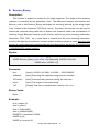
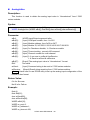
6.4 Digital Input/Output Functions
6.4.1 I-7000 series modules
DigitalOut
Description:
This function is used to output the value of the digital output module for I-7000 series
modules.
Syntax:
[ C]
WORD DigitalOut(WORD wBuf[], float fBuf[], char szSend[], char szReceive[])
Parameter:
wBuf:
WORD Input/Output argument talbe
wBuf[0] :
[Input] COM port number, from 1 to 255
wBuf[1] :
[Input] Module address, form 0x00 to 0xFF
wBuf[2] :
[Input] Module ID, 0x7011/12/14/42/43/44/50/60/63/65/66/67/80
wBuf[3] :
[Input] 0= Checksum disable; 1= Checksum enable
wBuf[4] :
[Input] Timeout setting , normal=100 msecond
wBuf[5] : : [Input] 16-bit digital output data
wBuf[6] :
[Input] 0 Æ no save to szSend &szReceive
1 Æ Save to szSend &szReceive
fBuf :
Not used.
szSend :
[Input] Command string to be sent to I-7000 series modules.
szReceive : [Output] Result string receiving from I-7000 series modules .
Return Value:
0 is for Success
Not 0 is for Failure
Example:
char szSend[80];
char szReceive[80];
float fBuf[12];
WORD wBuf[12];
WORD m_port=3;
WORD m_address=1;
WORD m_timeout=100;
LinPAC-5000 SDK Manual:64
WORD m_checksum=0;
Open_Com(COM3, 9600, Data8Bit, NonParity, OneStopBit);
wBuf[0] = m_port;
wBuf[1] = m_address;
wBuf[2] = 0x7050;
wBuf[3] = m_checksum;
wBuf[4] = m_timeout;
wBuf[5] = 0x0f;
// 8 DO Channels On
wBuf[6] = 0;
DigitalOut(wBuf, fBuf, szSend, szReceive);
Close_Com(COM3);
Remark:
DigitalBitOut
Description:
This function is used to set digital output value of the channel No. of I-7000 series
modules. The output value is “0” or “1”.
Syntax:
[ C]
WORD DigitalBitOut(WORD wBuf[ ], float fBuf[ ], char szSend[ ], char szReceive[ ])
Parameter:
wBuf:
WORD Input/Output argument talbe
wBuf[0] :
[Input] COM port number, from 1 to 255
wBuf[1] :
[Input] Module address, form 0x00 to 0xFF
wBuf[2] :
[Input] Module ID, 0x7042/43/44/50/60/63/65/66/67
wBuf[3] :
[Input] 0= Checksum disable; 1= Checksum enable
wBuf[4] :
[Input] Timeout setting , normal=100 msecond
wBuf[5] : : Not used
wBuf[6] :
[Input] 0 Æ no save to szSend &szReceive
1 Æ Save to szSend &szReceive
wBuf[7] :
[Input] The digital output channel No.
LinPAC-5000 SDK Manual:65
wBuf[8] :
[Input] Logic value(0 or 1)
fBuf :
Not used.
szSend :
[Input] Command string to be sent to I-7000 series modules.
szReceive : [Output] Result string receiving from I-7000 series modules .
Return Value:
0 is for Success
Not 0 is for Failure
Example:
char szSend[80];
char szReceive[80];
float fBuf[12];
WORD wBuf[12];
WORD m_port=3;
WORD m_address=1;
WORD m_timeout=100;
WORD m_checksum=0;
Open_Com(COM3, 9600, Data8Bit, NonParity, OneStopBit);
wBuf[0] = m_port;
wBuf[1] = m_address;
wBuf[2] = 0x7065;
wBuf[3] = m_checksum;
wBuf[4] = m_timeout;
wBuf[6] = 0;
wBuf[7] = 0x08;
//RL4 relay On
wBuf[8] = 1;
DigitalBitOut (wBuf, fBuf, szSend, szReceive);
Close_Com(COM3);
Remark:
LinPAC-5000 SDK Manual:66
DigitalOutReadBack
Description:
This function is used to read back the digital output value of I-7000 series modules.
Syntax:
[ C]
WORD DigitalOutReadBack(WORD wBuf[ ], float fBuf[ ],char szSend[ ],
char szReceive[ ])
Parameter:
wBuf:
WORD Input/Output argument talbe
wBuf[0] :
[Input] COM port number, from 1 to 255
wBuf[1] :
[Input] Module address, form 0x00 to 0xFF
wBuf[2] :
[Input] Module ID, 0x7042/43/44/50/60/63/65/66/67/80
wBuf[3] :
[Input] 0=Checksum disable; 1=Checksum enable
wBuf[4] :
[Input] Timeout setting , normal=100 msecond
wBuf[5] : : [Output] 16-bit digital output data read back
wBuf[6] :
[Input] 0 Æ no save to szSend &szReceive
1 Æ Save to szSend &szReceive
fBuf :
Not used.
szSend :
[Input] Command string to be sent to I-7000 series modules.
szReceive : [Output] Result string receiving from I-7000 series modules .
Return Value:
0 is for Success
Not 0 is for Failure
Example:
char szSend[80];
char szReceive[80];
float fBuf[12];
WORD DO;
WORD wBuf[12];
WORD m_port=3;
WORD m_address=1;
WORD m_timeout=100;
WORD m_checksum=0;
Open_Com(COM3, 9600, Data8Bit, NonParity, OneStopBit);
wBuf[0] = m_port;
wBuf[1] = m_address;
LinPAC-5000 SDK Manual:67
wBuf[2] = 0x7050;
wBuf[3] = m_checksum;
wBuf[4] = m_timeout;
wBuf[6] = 0;
DigitalOutReadBack (wBuf, fBuf, szSend, szReceive);
DO=wBuf[5];
Close_Com(COM3);
Remark:
DigitalOut_7016
Description:
This function is used to set the digital output value of the specified channel No. of I-7016
module. If the parameter of wBuf[7] is “0”, it means to output the digital value through Bit0
and Bit1 digital output channels. If wBuf[7] is “1”, it means to output the digital value through
Bit2 and Bit3 digital output channels.
Syntax:
[ C]
WORD DigitalOut_7016(WORD wBuf[], float fBuf[], char szSend[], char szReceive[])
Parameter:
wBuf:
WORD Input/Output argument talbe
wBuf[0] :
[Input] COM port number, from 1 to 255
wBuf[1] :
[Input] Module address, form 0x00 to 0xFF
wBuf[2] :
[Input] Module ID, 0x7016
wBuf[3] :
[Input] 0= Checksum disable; 1= Checksum enable
wBuf[4] :
[Input] Timeout setting , normal=100 msecond
wBuf[5] : : [Input] 2-bit digital output data in decimal format
wBuf[6] :
[Input] 0 Æ no save to szSend &szReceive
1 Æ Save to szSend &szReceive
wBuf[7] :
[Input] 0 : Bit0, Bit1 output
1 : Bit2, Bit3 output
fBuf :
Not used.
szSend :
[Input] Command string to be sent to I-7000 series modules.
LinPAC-5000 SDK Manual:68
szReceive :
[Output] Result string receiving from I-7000 series modules .
Return Value:
0 is for Success
Not 0 is for Failure
Example:
char szSend[80];
char szReceive[80];
float fBuf[12];
WORD wBuf[12];
WORD m_port=3;
WORD m_address=1;
WORD m_timeout=100;
WORD m_checksum=0;
Open_Com(COM3, 9600, Data8Bit, NonParity, OneStopBit);
wBuf[0] = m_port;
wBuf[1] = m_address;
wBuf[2] = 0x7016;
wBuf[3] = m_checksum;
wBuf[4] = m_timeout;
wBuf[5] = 1;
wBuf[6] = 0;
wBuf[7] = 1;
// Set the Bit2, Bit3 digital output
DigitalOut_7016(wBuf, fBuf, szSend, szReceive);
Close_Com(COM3);
Remark:
LinPAC-5000 SDK Manual:69
DigitalIn
Description:
This function is used to obtain the digital input value from I-7000 series modules.
Syntax:
[ C]
WORD DigitalIn(WORD wBuf[], float fBuf[], char szSend[], char szReceive[])
Parameter:
wBuf:
wBuf[0] :
wBuf[1] :
wBuf[2] :
wBuf[3] :
WORD Input/Output argument talbe
[Input] COM port number, from 1 to 255
[Input] Module address, form 0x00 to 0xFF
[Input] Module ID, 0x7041/44/50/52/53/55/58/60/63/65
[Input] 0= Checksum disable; 1= Checksum enable
wBuf[4] :
[Input] Timeout setting , normal=100 msecond
wBuf[5] : : [Output] 16-bit digital output data
wBuf[6] :
[Input] 0 Æ no save to szSend &szReceive
1 Æ Save to szSend &szReceive
fBuf :
Not used.
szSend :
[Input] Command string to be sent to I-7000 series modules.
szReceive : [Output] Result string receiving from I-7000 series modules .
Return Value:
0 is for Success
Not 0 is for Failure
Example:
char szSend[80];
char szReceive[80];
float fBuf[12];
WORD DI;
WORD wBuf[12];
WORD m_port=3;
WORD m_address=1;
WORD m_timeout=100;
WORD m_checksum=0;
Open_Com(COM3, 9600, Data8Bit, NonParity, OneStopBit);
wBuf[0] = m_port;
wBuf[1] = m_address;
wBuf[2] = 0x7050;
LinPAC-5000 SDK Manual:70
wBuf[3] = m_checksum;
wBuf[4] = m_timeout;
wBuf[6] = 0;
DigitalIn(wBuf, fBuf, szSend, szReceive);
DI=wBuf[5];
Close_Com(COM3);
Remark:
DigitalInLatch
Description:
This function is used to obtain the latch value of the high or low latch mode of digital
input module.
Syntax:
[ C]
WORD DigitalInLatch(WORD wBuf[], float fBuf[], char szSend[], char szReceive[])
Parameter:
wBuf:
WORD Input/Output argument talbe
wBuf[0] :
[Input] COM port number, from 1 to 255
wBuf[1] :
[Input] Module address, form 0x00 to 0xFF
wBuf[2] :
[Input] Module ID, 0x7041/44/50/52/53/55/58/60/63/65/66
wBuf[3] :
[Input] 0= Checksum disable; 1= Checksum enable
wBuf[4] :
[Input] Timeout setting , normal=100 msecond
wBuf[5] : : [Input] 0: low Latch mode ; 1:high Latch mode
wBuf[6] :
[Input] 0 Æ no save to szSend &szReceive
1 Æ Save to szSend &szReceive
wBuf[7] :
[Output] Latch value
fBuf :
Not used.
szSend :
[Input] Command string to be sent to I-7000 series modules.
szReceive : [Output] Result string receiving from I-7000 series modules .
Return Value:
0 is for Success
Not 0 is for Failure
LinPAC-5000 SDK Manual:71
Example:
char szSend[80];
char szReceive[80];
float fBuf[12];
WORD wBuf[12];
WORD m_port=3;
WORD m_address=1;
WORD m_timeout=100;
WORD m_checksum=0;
Open_Com(COM3, 9600, Data8Bit, NonParity, OneStopBit);
wBuf[0] = m_port ;
wBuf[1] = m_address ;
wBuf[2] = 0x7050;
wBuf[3] = m_checksum ;
wBuf[4] = m_timeout ;
wBuf[5] = 1;
// Set the high Latch mode
wBuf[6] = 0;
wBuf[7] = 0x03;
// Set the Latch value
DigitalInLatch(wBuf, fBuf, szSend, szReceive);
Close_Com(COM3);
Remark:
LinPAC-5000 SDK Manual:72
ClearDigitalInLatch
Description:
This function is used to clear the latch status of digital input module when latch function
has been enable.
Syntax:
[ C]
WORD ClearDigitalInLatch(WORD wBuf[], float fBuf[],char szSend[],
char szReceive[])
Parameter:
wBuf:
wBuf[0] :
wBuf[1] :
WORD Input/Output argument talbe
[Input] COM port number, from 1 to 255
[Input] Module address, form 0x00 to 0xFF
wBuf[2] :
[Input] Module ID, 0x7011/12/14/42/43/44/50/55/58/60/63/65/66/67
wBuf[3] :
[Input] 0= Checksum disable; 1= Checksum enable
wBuf[4] :
[Input] Timeout setting , normal=100 msecond
wBuf[5] : : Not used.
wBuf[6] :
[Input] 0 Æ no save to szSend &szReceive
1 Æ Save to szSend &szReceive
fBuf :
Not used.
szSend :
[Input] Command string to be sent to I-7000 series modules.
szReceive : [Output] Result string receiving from I-7000 series modules .
Return Value:
0 is for Success
Not 0 is for Failure
Example:
char szSend[80];
char szReceive[80];
float fBuf[12];
WORD wBuf[12];
WORD m_port=3;
WORD m_address=1;
WORD m_timeout=100;
WORD m_checksum=0;
Open_Com(COM3, 9600, Data8Bit, NonParity, OneStopBit);
wBuf[0] = m_port;
LinPAC-5000 SDK Manual:73
wBuf[1] = m_address;
wBuf[2] = 0x7050;
wBuf[3] = m_checksum;
wBuf[4] = m_timeout;
wBuf[6] = 0;
ClearDigitalInLatch(wBuf, fBuf, szSend, szReceive);
Close_Com(COM3);
Remark:
DigitalInCounterRead
Description:
This function is used to obtain the counter event value of the channel number of digital
input module.
Syntax:
[ C]
WORD DigitalInCounterRead(WORD wBuf[], float fBuf[], char szSend[],
char szReceive[])
Parameter:
wBuf:
WORD Input/Output argument talbe
wBuf[0] :
[Input] COM port number, from 1 to 255
wBuf[1] :
[Input] Module address, form 0x00 to 0xFF
wBuf[2] :
[Input] Module ID, 0x7041/44/50/51/52/53/55/58/60/63/65
wBuf[3] :
[Input] 0= Checksum disable; 1= Checksum enable
wBuf[4] :
[Input] Timeout setting , normal=100 msecond
wBuf[5] : : [Input] The digital input Channel No.
wBuf[6] :
[Input] 0 Æ no save to szSend &szReceive
1 Æ Save to szSend &szReceive
wBuf[7] :
[Output] Counter value of the digital input channel No.
fBuf :
Not used.
szSend :
[Input] Command string to be sent to I-7000 series modules.
szReceive : [Output] Result string receiving from I-7000 series modules .
LinPAC-5000 SDK Manual:74
Return Value:
0 is for Success
Not 0 is for Failure
Example:
char szSend[80];
char szReceive[80];
float fBuf[12];
WORD DI_counter;
WORD wBuf[12];
WORD m_port=3;
WORD m_address=1;
WORD m_timeout=100;
WORD m_checksum=0;
Open_Com(COM3, 9600, Data8Bit, NonParity, OneStopBit);
wBuf[0] = m_port;
wBuf[1] = m_address;
wBuf[2] = 0x7050;
wBuf[3] = m_checksum;
wBuf[4] = 100;
wBuf[5] = 0;
// Set the digital input channel No.
wBuf[6] = 0;
DigitalInCounterRead(wBuf, fBuf, szSend, szReceive);
DI_counter=wBuf[7];
Close_Com(COM3);
Remark:
LinPAC-5000 SDK Manual:75
ClearDigitalInCounter
Description:
This function is used to clear the counter value of the channel number of digital input
module.
Syntax:
[ C]
WORD ClearDigitalInCounter(WORD wBuf[], float fBuf[],char szSend[],
char szReceive[])
Parameter:
wBuf:
wBuf[0] :
wBuf[1] :
WORD Input/Output argument talbe
[Input] COM port number, from 1 to 255
[Input] Module address, form 0x00 to 0xFF
wBuf[2] :
[Input] Module ID, 0x7041/44/50/51/52/53/55/58/60/63/65
wBuf[3] :
[Input] 0= Checksum disable; 1= Checksum enable
wBuf[4] :
[Input] Timeout setting , normal=100 msecond
wBuf[5] : : [Input] The digital input channel No.
wBuf[6] :
[Input] 0 Æ no save to szSend &szReceive
1 Æ Save to szSend &szReceive
fBuf :
Not used.
szSend :
[Input] Command string to be sent to I-7000 series modules.
szReceive : [Output] Result string receiving from I-7000 series modules .
Return Value:
0 is for Success
Not 0 is for Failure
Example:
char szSend[80];
char szReceive[80];
float fBuf[12];
WORD wBuf[12];
WORD m_port=3;
WORD m_address=1;
WORD m_timeout=100;
WORD m_checksum=0;
Open_Com(COM3, 9600, Data8Bit, NonParity, OneStopBit);
wBuf[0] = m_port;
LinPAC-5000 SDK Manual:76
wBuf[1] = m_address;
wBuf[2] = 0x7050;
wBuf[3] = m_checksum;
wBuf[4] = m_timeout;
wBuf[5] = 0;
// Set the digital input channel No.
wBuf[6] = 0;
ClearDigitalInCounter(wBuf, fBuf, szSend, szReceive);
Close_Com(COM3);
Remark:
ReadEventCounter
Description:
This function is used to obtain the value of event counter of I-7000 series modules. This
function only supports I-7011, I-7012, I-7014 and I-7016 modules.
Syntax:
[ C]
WORD ReadEventCounter(WORD wBuf[], float fBuf[],char szSend[],
char szReceive[])
Parameter:
wBuf:
WORD Input/Output argument talbe
wBuf[0] :
[Input] COM port number, from 1 to 255
wBuf[1] :
[Input] Module address, form 0x00 to 0xFF
wBuf[2] :
[Input] Module ID, 0x7011/12/14/16
wBuf[3] :
[Input] 0= Checksum disable; 1= Checksum enable
wBuf[4] :
[Input] Timeout setting , normal=100 msecond
wBuf[5] : : Not used
wBuf[6] :
[Input] 0 Æ no save to szSend &szReceive
1 Æ Save to szSend &szReceive
wBuf[7] :
[Output] The value of event counter
fBuf :
Not used.
szSend :
[Input] Command string to be sent to I-7000 series modules.
szReceive : [Output] Result string receiving from I-7000 series modules .
LinPAC-5000 SDK Manual:77
Return Value:
0 is for Success
Not 0 is for Failure
Example:
char szSend[80];
char szReceive[80];
float fBuf[12];
WORD Counter;
WORD wBuf[12];
WORD m_port=3;
WORD m_address=1;
WORD m_timeout=100;
WORD m_checksum=0;
Open_Com(COM3, 9600, Data8Bit, NonParity, OneStopBit);
wBuf[0] = m_port;
wBuf[1] = m_address;
wBuf[2] = 0x7012;
wBuf[3] = m_checksum;
wBuf[4] = m_timeout;
wBuf[6] = 0;
ReadEventCounter (wBuf, fBuf, szSend, szReceive);
Counter=wBuf[7];
Close_Com(COM3);
Remark:
LinPAC-5000 SDK Manual:78
ClearEventCounter
Description:
This function is used to clear the value of event counter of I-7000 series modules. This
function only supports I-7011, I-7012, I-7014 and I-7016 modules.
Syntax:
[ C]
WORD ClearEventCounter(WORD wBuf[], float fBuf[], char szSend[],
char szReceive[])
Parameter:
wBuf:
wBuf[0] :
wBuf[1] :
WORD Input/Output argument talbe
[Input] COM port number, from 1 to 255
[Input] Module address, form 0x00 to 0xFF
wBuf[2] :
[Input] Module ID, 0x7011/12/14/16
wBuf[3] :
[Input] 0= Checksum disable; 1= Checksum enable
wBuf[4] :
[Input] Timeout setting , normal=100 msecond
wBuf[5] : : Not used
wBuf[6] :
[Input] 0 Æ no save to szSend &szReceive
1 Æ Save to szSend &szReceive
fBuf :
Not used.
szSend :
[Input] Command string to be sent to I-7000 series modules.
szReceive : [Output] Result string receiving from I-7000 series modules .
Return Value:
0 is for Success
Not 0 is for Failure
Example:
char szSend[80];
char szReceive[80];
float fBuf[12];
WORD wBuf[12];
WORD m_port=3;
WORD m_address=1;
WORD m_timeout=100;
WORD m_checksum=0;
Open_Com(COM3, 9600, Data8Bit, NonParity, OneStopBit);
wBuf[0] = m_port;
LinPAC-5000 SDK Manual:79
wBuf[1] = m_address;
wBuf[2] = 0x7012;
wBuf[3] = m_checksum;
wBuf[4] = m_timeout;
wBuf[6] = 0;
ClearEventCounter (wBuf, fBuf, szSend, szReceive);
Close_Com(COM3);
Remark:
LinPAC-5000 SDK Manual:80
6.5 Analog Input Functions
6.5.1 I-7000 series modules
AnalogIn
Description:
This function is used to obtain input value form I-7000 series modules.
Syntax:
[ C]
WORD AnalogIn (WORD wBuf[], float fBuf[],char szSend[],char szReceive[])
Parameter:
wBuf:
WORD Input/Output argument talbe
wBuf[0] :
[Input] COM port number, from 1 to 255
wBuf[1] :
[Input] Module address, form 0x00 to 0xFF
wBuf[2] :
[Input] Module ID, 0x7005/11/12/13/14/15/16/17/18/19/33
wBuf[3] :
[Input] 0= Checksum disable; 1= Checksum enable
wBuf[4] :
[Input] Timeout setting , normal=100 msecond
wBuf[5] : : [Input] Channel number for multi-channel
wBuf[6] :
[Input] 0 Æ no save to szSend & szReceive
1 Æ Save to szSend & szReceive
fBuf :
Float Input/Ouput argument table.
fBuf[0] : :: :: [Output] Analog input value return
szSend :
[Input] Command string to be sent to I-7000 series modules.
szReceive : [Output] Result string receiving from I-7000 series modules .
Note : “wBuf[6]” is the debug setting. If this parameter is set as “1”, user can get
whole command string and result string from szSend[] and szReceive[] respectively.
Return Value:
0 is for Success
Not 0 is for Failure
Example:
float AI;
float fBuf[12];
char szSend[80];
char szReceive[80];
WORD wBuf[12];
WORD m_port=3;
LinPAC-5000 SDK Manual:81
WORD m_address=1;
WORD m_timeout=100;
WORD m_checksum=0;
Open_Com(COM3, 9600, Data8Bit, NonParity, OneStopBit);
wBuf[0] = m_port;
wBuf[1] = m_address;
wBuf[2] = 0x7016;
wBuf[3] = m_checksum;
wBuf[4] = m_timeout;
wBuf[5] = 0;
wBuf[6] = 1;
AnalogIn (wBuf, fBuf, szSend, szReceive);
// szSend=”#02” , szReceive=”>+001.9”
AI = fBuf[0];
// AI = 1.9
Close_Com(COM3);
Remark:
LinPAC-5000 SDK Manual:82
AnalogInHex
Description:
This function is used to obtain the analog input value in “Hexadecimal” form I-7000
series modules.
Syntax:
[ C]
WORD AnalogInHex (WORD wBuf[], float fBuf[],char szSend[],char szReceive[])
Parameter:
wBuf:
WORD Input/Output argument talbe
wBuf[0] :
[Input] COM port number, from 1 to 255
wBuf[1] :
[Input] Module address, form 0x00 to 0xFF
wBuf[2] :
[Input] Module ID, 0x7005/11/12/13/14/15/16/17/18/19/33
wBuf[3] :
[Input] 0= Checksum disable; 1= Checksum enable
wBuf[4] :
[Input] Timeout setting , normal=100 msecond
wBuf[5] : : : [Input] Channel number for multi-channel
wBuf[6] :
[Input] 0 Æ no save to szSend & szReceive
1 Æ Save to szSend & szReceive
wBuf[7] :
[Ouput] The analog input value in “Hexadecimal “ format
fBuf :
Not used.
szSend :
[Input] Command string to be sent to I-7000 series modules.
szReceive : [Output] Result string receiving from I-7000 series modules .
Note : Users have to use DCON utility to set up the analog input configuration of the
module in hex format.
Return Value:
0 is for Success
Not 0 is for Failure
Example:
float AI;
float fBuf[12];
char szSend[80];
char szReceive[80];
WORD wBuf[12];
WORD m_port=3;
WORD m_address=1;
WORD m_timeout=100;
LinPAC-5000 SDK Manual:83
WORD m_checksum=0;
Open_Com(COM3, 9600, Data8Bit, NonParity, OneStopBit);
wBuf[0] = m_port;
wBuf[1] = m_address;
wBuf[2] = 0x7012;
wBuf[3] = m_checksum;
wBuf[4] = m_timeout;
wBuf[5] = 0;
wBuf[6] = 1;
AnalogInHex (wBuf, fBuf, szSend, szReceive);
AI = wBuf[7];
// Hex format
Close_Com(COM3);
Remark:
AnalogInFsr
Description:
This function is used to obtain the analog input value in “FSR” format form I-7000 series
modules. The “FSR” means “Percent” format.
Syntax:
[ C]
WORD AnalogInFsr (WORD wBuf[], float fBuf[],char szSend[],char szReceive[])
Parameter:
wBuf:
WORD Input/Output argument talbe
wBuf[0] :
[Input] COM port number, from 1 to 255
wBuf[1] :
[Input] Module address, form 0x00 to 0xFF
wBuf[2] :
[Input] Module ID, 0x7005/11/12/13/14/15/16/17/18/19/33
wBuf[3] :
[Input] 0= Checksum disable; 1= Checksum enable
wBuf[4] :
[Input] Timeout setting , normal=100 msecond
wBuf[5] : : : [Input] Channel number for multi-channel
wBuf[6] :
[Input] 0 Æ no save to szSend & szReceive
1 Æ Save to szSend &szReceive
LinPAC-5000 SDK Manual:84
fBuf :
Float Input/Output argument table.
fBuf[0] : ::: [Output] Analog input value return
szSend :
[Input] Command string to be sent to I-7000 series modules.
szReceive : [Output] Result string receiving from I-7000 series modules .
Note : Users have to use DCON utility to set up the analog input configuration of the
module in hex format.
Return Value:
0 is for Success
Not 0 is for Failure
Example:
float AI;
float fBuf[12];
char szSend[80];
char szReceive[80];
WORD wBuf[12];
WORD m_port=3;
WORD m_address=1;
WORD m_timeout=100;
WORD m_checksum=0;
Open_Com(COM3, 9600, Data8Bit, NonParity, OneStopBit);
wBuf[0] = m_port;
wBuf[1] = m_address;
wBuf[2] = 0x7012;
wBuf[3] = m_checksum;
wBuf[4] = m_timeout;
wBuf[5] = 0;
wBuf[6] = 1;
AnalogInFsr (wBuf, fBuf, szSend, szReceive);
AI = wBuf[7];
Close_Com(COM3);
Remark:
LinPAC-5000 SDK Manual:85
AnalogInAll
Description:
This function is used to obtain the analog input value of all channels form I-7000 series
modules.
Syntax:
[ C]
WORD AnalogInAll (WORD wBuf[], float fBuf[],char szSend[],char szReceive[])
Parameter:
wBuf:
wBuf[0] :
wBuf[1] :
wBuf[2] :
wBuf[3] :
wBuf[4] :
wBuf[6] :
WORD Input/Output argument talbe
[Input] COM port number, from 1 to 255
[Input] Module address, form 0x00 to 0xFF
[Input] Module ID, 0x7005/15/16/17/18/19/33
[Input] 0= Checksum disable; 1= Checksum enable
[Input] Timeout setting , normal=100 msecond
[Input] 0 Æ no save to szSend & szReceive
1 Æ Save to szSend & szReceive
fBuf :
Float Input/Output argument table.
fBuf[0] : ::: [Output] Analog input value return of channel_0
fBuf[1] : ::: [Output] Analog input value return of channel_1
fBuf[2] : ::: [Output] Analog input value return of channel_2
fBuf[3] : ::: [Output] Analog input value return of channel_3
fBuf[4] : ::: [Output] Analog input value return of channel_4
fBuf[5] : ::: [Output] Analog input value return of channel_5
fBuf[6] : ::: [Output] Analog input value return of channel_6
fBuf[7] : ::: [Output] Analog input value return of channel_7
szSend :
[Input] Command string to be sent to I-7000 series modules.
szReceive : [Output] Result string receiving from I-7000 series modules .
Note : Users have to use DCON utility to set up the analog input configuration of the
module in hex format.
Return Value:
0 is for Success
Not 0 is for Failure
Example:
float AI[12];
float fBuf[12];
LinPAC-5000 SDK Manual:86
char szSend[80];
char szReceive[80];
WORD wBuf[12];
WORD m_port=3;
WORD m_address=1;
WORD m_timeout=100;
WORD m_checksum=0;
Open_Com(COM3, 9600, Data8Bit, NonParity, OneStopBit);
wBuf[0] = m_port;
wBuf[1] = m_address;
wBuf[2] = 0x7017;
wBuf[3] = m_checksum;
wBuf[4] = m_timeout;
wBuf[6] = 1;
AnalogInAll (wBuf, fBuf, szSend, szReceive);
AI[0] = fBuf[0];
AI[0] = fBuf[1];
AI[0] = fBuf[2];
AI[0] = fBuf[3];
AI[0] = fBuf[4];
AI[0] = fBuf[5];
AI[0] = fBuf[6];
AI[0] = fBuf[7];
Close_Com(COM3);
Remark:
LinPAC-5000 SDK Manual:87
ThermocoupleOpen_7011
Description:
This function is used to detect the thermocouple state of I-7011 modules for the
supporting type “J, K, T, E, R, S, B, N, C” is open or close. If the response value is “0”,
thermocouple I-7011 is working in close state. If the response value is “1”, thermocouple
I-7011 is working in open state. For more information please refer to user manual.
Syntax:
[ C]
WORD ThermocoupleOpen_7011(WORD wBuf[], float fBuf[],char szSend[],
char szReceive[])
Parameter:
wBuf:
WORD Input/Output argument talbe
wBuf[0] :
[Input] COM port number, from 1 to 255
wBuf[1] :
[Input] Module address, form 0x00 to 0xFF
wBuf[2] :
[Input] Module ID, 0x7011
wBuf[3] :
[Input] 0= Checksum disable; 1= Checksum enable
wBuf[4] :
[Input] Timeout setting , normal=100 msecond
wBuf[5] : : : [Output] response value 0 Æ the thermocouple is close
:response value 1 Æ the thermocouple is open
wBuf[6] :
[Input] 0 Æ no save to szSend & szReceive
1 Æ Save to szSend & szReceive
fBuf :
Not used.
szSend :
[Input] Command string to be sent to I-7000 series modules.
szReceive : [Output] Result string receiving from I-7000 series modules .
Return Value:
0 is for Success
Not 0 is for Failure
Example:
WORD state;
float fBuf[12];
char szSend[80];
char szReceive[80];
WORD wBuf[12];
WORD m_port=3;
WORD m_address=1;
LinPAC-5000 SDK Manual:88
WORD m_timeout=100;
WORD m_checksum=0;
Open_Com(COM3, 9600, Data8Bit, NonParity, OneStopBit);
wBuf[0] = m_port;
wBuf[1] = m_address;
wBuf[2] = 0x7011;
wBuf[3] = m_checksum;
wBuf[4] = m_timeout;
wBuf[5] = 0;
wBuf[6] = 1;
ThermocoupleOpen_7011(wBuf, fBuf, szSend, szReceive);
state = wBuf[5];
Close_Com(COM3);
Remark:
SetLedDisplay
Description:
This function is used to configure LED display for specified channel of I-7000 analog
input serial modules.
Syntax:
[ C]
WORD SetLedDisplay (WORD wBuf[], float fBuf[],char szSend[], char szReceive[])
Parameter:
wBuf:
WORD Input/Output argument talbe
wBuf[0] :
[Input] COM port number, from 1 to 255
wBuf[1] :
[Input] Module address, form 0x00 to 0xFF
wBuf[2] :
[Input] Module ID, 0x7013/16/33
wBuf[3] :
[Input] 0= Checksum disable; 1= Checksum enable
wBuf[4] :
[Input] Timeout setting , normal=100 msecond
wBuf[5] : : : [Input] Set display channel
LinPAC-5000 SDK Manual:89
wBuf[6] :
[Input] 0 Æ no save to szSend & szReceive
1 Æ Save to szSend & szReceive
fBuf :
Not used.
szSend :
[Input] Command string to be sent to I-7000 series modules.
szReceive : [Output] Result string receiving from I-7000 series modules .
Return Value:
0 is for Success
Not 0 is for Failure
Example:
float fBuf[12];
char szSend[80];
char szReceive[80];
WORD wBuf[12];
WORD m_port=3;
WORD m_address=1;
WORD m_timeout=100;
WORD m_checksum=0;
Open_Com(COM3, 9600, Data8Bit, NonParity, OneStopBit);
wBuf[0] = m_port;
wBuf[1] = m_address;
wBuf[2] = 0x7033;
wBuf[3] = m_checksum;
wBuf[4] = m_timeout;
wBuf[5] = 1;
// Set channel 1 display
wBuf[6] = 1;
SetLedDisplay (wBuf, fBuf, szSend, szReceive);
Close_Com(COM3);
Remark:
LinPAC-5000 SDK Manual:90
GetLedDisplay
Description:
This function is used to get the current setting of the specified channel for LED display
channel for specified channel of I-7000 analog input serial modules.
Syntax:
[ C]
WORD GetLedDisplay (WORD wBuf[], float fBuf[],char szSend[], char szReceive[])
Parameter:
wBuf:
WORD Input/Output argument talbe
wBuf[0] :
[Input] COM port number, from 1 to 255
wBuf[1] :
[Input] Module address, form 0x00 to 0xFF
wBuf[2] :
[Input] Module ID, 0x7013/16/33
wBuf[3] :
[Input] 0= Checksum disable; 1= Checksum enable
wBuf[4] :
[Input] Timeout setting , normal=100 msecond
wBuf[5] : : : [Output] Current channel for LED display
0 = channel_0
1 = channel_1
wBuf[6] :
[Input] 0 Æ no save to szSend & szReceive
1 Æ Save to szSend & szReceive
fBuf :
Not used
szSend :
[Input] Command string to be sent to I-7000 series modules.
szReceive : [Output] Result string receiving from I-7000 series modules .
Return Value:
0 is for Success
Not 0 is for Failure
Example:
WORD led;
float fBuf[12];
char szSend[80];
char szReceive[80];
WORD wBuf[12];
WORD m_port=3;
WORD m_address=1;
WORD m_timeout=100;
WORD m_checksum=0;
LinPAC-5000 SDK Manual:91
Open_Com(COM3, 9600, Data8Bit, NonParity, OneStopBit);
wBuf[0] = m_port;
wBuf[1] = m_address;
wBuf[2] = 0x7033;
wBuf[3] = m_checksum;
wBuf[4] = m_timeout;
wBuf[6] = 1;
GetLedDisplay (wBuf, fBuf, szSend, szReceive);
Led = wBuf[5];
Close_Com(COM3);
Remark:
LinPAC-5000 SDK Manual:92
6.6 Analog Output Functions
6.6.1 I-7000 series modules
AnalogOut
Description:
This function is used to obtain analog value from analog output module of I-7000 series
modules.
Syntax:
[ C]
WORD AnalogOut(WORD wBuf[], float fBuf[],char szSend[], char szReceive[])
Parameter:
wBuf:
WORD Input/Output argument talbe
wBuf[0] :
[Input] COM port number, from 1 to 255
wBuf[1] :
[Input] Module address, form 0x00 to 0xFF
wBuf[2] :
[Input] Module ID, 0x7016/21/22/24
wBuf[3] :
[Input] 0= Checksum disable; 1= Checksum enable
wBuf[4] :
[Input] Timeout setting , normal=100 msecond
wBuf[5] : : [Input] The analog output channel number
wBuf[6] :
[Input] 0 Æ no save to szSend &szReceive
1 Æ Save to szSend &szReceive
fBuf :
Float Input/Ouput argument table.
fBuf[0] : :: :: [Input] Analog output value
szSend :
[Input] Command string to be sent to I-7000 series modules.
szReceive : [Output] Result string receiving from I-7000 series modules.
Return Value:
0 is for Success
Not 0 is for Failure
Example:
float fBuf[12];
char szSend[80];
char szReceive[80];
WORD wBuf[12];
WORD m_port=3;
WORD m_address=1;
LinPAC-5000 SDK Manual:93
WORD m_timeout=100;
WORD m_checksum=0;
Open_Com(COM3, 9600, Data8Bit, NonParity, OneStopBit);
wBuf[0] = m_port;
wBuf[1] = m_address;
wBuf[2] = 0x7016;
wBuf[3] = m_checksum;
wBuf[4] = m_timeout;
// wBuf[5] = 0;
// I-7016 no used
wBuf[6] = 1;
fBuf[0] = 3.5
// Excitation Voltage output +3.5V
AnalogOut (wBuf, fBuf, szSend, szReceive); ”
Close_Com(COM3);
Remark:
LinPAC-5000 SDK Manual:94
AnalogOutReadBack
Description:
This function is used to obtain read back the analog value of analog output modules
of
I-7000 series modules. There are two types of read back functions, as described in the
following :
1. Last value is read back by $AA6 command
2. Analog output of current path is read back by $AA8 command
Syntax:
[ C]
WORD AnalogOutReadBack(WORD wBuf[], float fBuf[],char szSend[],
char szReceive[])
Parameter:
wBuf:
wBuf[0] :
wBuf[1] :
wBuf[2] :
wBuf[3] :
wBuf[4] :
wBuf[5] : :
WORD Input/Output argument talbe
[Input] COM port number, from 1 to 255
[Input] Module address, form 0x00 to 0xFF
[Input] Module ID, 0x7016/21/22/24
[Input] 0= Checksum disable; 1= Checksum enable
[Input] Timeout setting , normal=100 msecond
[Input] 0 : command $AA6 read back
: 1 : command $AA8 read back
Note 1) When the module is I-7016: Don’t care.
:: 2) When the module is I-7021/22, analog output of current path
read back ($AA8)
:
3) When the module is I-7024, the updating value in a specific
Slew rate ($AA8)
(For more information, please refer to I-7021/22/24 manual)
wBuf[6] :
[Input] 0 Æ no save to szSend &szReceive
1 Æ Save to szSend &szReceive
wBuf[7] :
[Input] The analog output channel No. (0~3) of module I-7024
No used for single analog output module
fBuf :
Float Input/Ouput argument table.
fBuf[0] : :: :: [Output] Analog output read back value
szSend :
[Input] Command string to be sent to I-7000 series modules.
szReceive : [Output] Result string receiving from I-7000 series modules.
Return Value:
LinPAC-5000 SDK Manual:95
0 is for Success
Not 0 is for Failure
Example:
Float Volt;
float fBuf[12];
char szSend[80];
char szReceive[80];
WORD wBuf[12];
WORD m_port=3;
WORD m_address=1;
WORD m_timeout=100;
WORD m_checksum=0;
Open_Com(COM3, 9600, Data8Bit, NonParity, OneStopBit);
wBuf[0] = m_port;
wBuf[1] = m_address;
wBuf[2] = 0x7021;
wBuf[3] = m_checksum;
wBuf[4] = m_timeout;
wBuf[5] = 0;
// $AA6 command
wBuf[6] = 1;
wBuf[7] = 1;
AnalogOutReadBack (wBuf, fBuf, szSend, szReceive);
Volt = fBuf[0];
// Receive: “!01+2.57” excitation voltage , Volt=2.57
Close_Com(COM3);
Remark:
LinPAC-5000 SDK Manual:96
AnalogOutHex
Description:
This function is used to obtain analog value of analog output modules through Hex
format.
Syntax:
[ C]
WORD AnalogOutHex(WORD wBuf[], float fBuf[],char szSend[], char szReceive[])
Parameter:
wBuf:
wBuf[0] :
wBuf[1] :
wBuf[2] :
wBuf[3] :
wBuf[4] :
wBuf[5] : :
WORD Input/Output argument talbe
[Input] COM port number, from 1 to 255
[Input] Module address, form 0x00 to 0xFF
[Input] Module ID, 0x7021/21P/22
[Input] 0= Checksum disable; 1= Checksum enable
[Input] Timeout setting , normal=100 msecond
[Input] The analog output channel number
(No used for single analog output module)
wBuf[6] :
[Input] 0 Æ no save to szSend &szReceive
1 Æ Save to szSend &szReceive
wBuf[7] : :: :[Input] Analog output value in Hexadecimal data format
fBuf :
Not used.
szSend :
[Input] Command string to be sent to I-7000 series modules.
szReceive : [Output] Result string receiving from I-7000 series modules.
Return Value:
0 is for Success
Not 0 is for Failure
Example:
float fBuf[12];
char szSend[80];
char szReceive[80];
WORD wBuf[12];
WORD m_port=3;
WORD m_address=1;
WORD m_timeout=100;
WORD m_checksum=0;
Open_Com(COM3, 9600, Data8Bit, NonParity, OneStopBit);
LinPAC-5000 SDK Manual:97
wBuf[0] = m_port;
wBuf[1] = m_address;
wBuf[2] = 0x7022;
wBuf[3] = m_checksum;
wBuf[4] = m_timeout;
wBuf[5] = 1;
// channel 1
wBuf[6] = 1;
wBuf[7] = 0x250
AnalogOutHex (wBuf, fBuf, szSend, szReceive);
Close_Com(COM3);
Remark:
AnalogOutFsr
Description:
This function is used to obtain analog value of analog output modules through % of
span data format. This function only can be used after analog output modules is set as
“FSR” output mode.
Syntax:
[ C]
WORD AnalogOutFsr(WORD wBuf[], float fBuf[],char szSend[], char szReceive[])
Parameter:
wBuf:
wBuf[0] :
wBuf[1] :
wBuf[2] :
wBuf[3] :
wBuf[4] :
wBuf[5] : :
wBuf[6] :
WORD Input/Output argument talbe
[Input] COM port number, from 1 to 255
[Input] Module address, form 0x00 to 0xFF
[Input] Module ID, 0x7021/21P/22
[Input] 0= Checksum disable; 1= Checksum enable
[Input] Timeout setting , normal=100 msecond
[Input] The analog output channel number
(No used for single analog output module)
[Input] 0 Æ no save to szSend &szReceive
1 Æ Save to szSend &szReceive
LinPAC-5000 SDK Manual:98
fBuf :
Float Input/Output argument table.
FBuf[0] :
[Input] Analog output value in % of Span data format.
szSend :
[Input] Command string to be sent to I-7000 series modules.
szReceive : [Output] Result string receiving from I-7000 series modules.
Return Value:
0 is for Success
Not 0 is for Failure
Example:
float fBuf[12];
char szSend[80];
char szReceive[80];
WORD wBuf[12];
WORD m_port=3;
WORD m_address=1;
WORD m_timeout=100;
WORD m_checksum=0;
Open_Com(COM3, 9600, Data8Bit, NonParity, OneStopBit);
wBuf[0] = m_port;
wBuf[1] = m_address;
wBuf[2] = 0x7022;
wBuf[3] = m_checksum;
wBuf[4] = m_timeout;
wBuf[5] = 1;
// channel 1
wBuf[6] = 1;
fBuf[0] = 50
AnalogOutFsr (wBuf, fBuf, szSend, szReceive); ”
Close_Com(COM3);
Remark:
LinPAC-5000 SDK Manual:99
AnalogOutReadBackHex
Description:
This function is used to obtain read back the analog value of analog output modules in
Hex format for I-7000 series modules. There are two types of read back functions, as
described in the following :
1. Last value is read back by $AA6 command
2. Analog output of current path is read back by $AA8 command
Syntax:
[ C]
WORD AnalogOutReadBackHex(WORD wBuf[], float fBuf[],char szSend[],
char szReceive[])
Parameter:
wBuf:
wBuf[0] :
wBuf[1] :
wBuf[2] :
wBuf[3] :
wBuf[4] :
wBuf[5] : :
WORD Input/Output argument talbe
[Input] COM port number, from 1 to 255
[Input] Module address, form 0x00 to 0xFF
[Input] Module ID, 0x7021/21P/22
[Input] 0= Checksum disable; 1= Checksum enable
[Input] Timeout setting , normal=100 msecond
[Input] 0 : command $AA6 read back
: 1 : command $AA8 read back
wBuf[6] :
[Input] 0 Æ no save to szSend &szReceive
1 Æ Save to szSend &szReceive
wBuf[7] :
[Input] The analog output channel No.
No used for single analog output module
wBuf[9] : ::: [Output] Analog output value in Hexadecimal data format.
fBuf :
Not used.
szSend :
[Input] Command string to be sent to I-7000 series modules.
szReceive : [Output] Result string receiving from I-7000 series modules.
Return Value:
0 is for Success
Not 0 is for Failure
Example:
WORD Volt;
float fBuf[12];
LinPAC-5000 SDK Manual:100
char szSend[80];
char szReceive[80];
WORD wBuf[12];
WORD m_port=3;
WORD m_address=1;
WORD m_timeout=100;
WORD m_checksum=0;
Open_Com(COM3, 9600, Data8Bit, NonParity, OneStopBit);
wBuf[0] = m_port;
wBuf[1] = m_address;
wBuf[2] = 0x7021;
wBuf[3] = m_checksum;
wBuf[4] = m_timeout;
wBuf[5] = 0;
// command $AA6
wBuf[6] = 1;
wBuf[7] = 0;
AnalogOutReadBackHex (wBuf, fBuf, szSend, szReceive);
Volt = wBuf[9];
Close_Com(COM3);
Remark:
LinPAC-5000 SDK Manual:101
AnalogOutReadBackFsr
Description:
This function is used to obtain read back the analog value of analog output modules
throuth % of span data format for I-7000 series modules. There are two types of read back
functions, as described in the following :
1. Last value is read back by $AA6 command
2. Analog output of current path is read back by $AA8 command
Syntax:
[ C]
WORD AnalogOutReadBackFsr(WORD wBuf[], float fBuf[],char szSend[],
char szReceive[])
Parameter:
wBuf:
wBuf[0] :
wBuf[1] :
wBuf[2] :
wBuf[3] :
wBuf[4] :
wBuf[5] : :
WORD Input/Output argument talbe
[Input] COM port number, from 1 to 255
[Input] Module address, form 0x00 to 0xFF
[Input] Module ID, 0x7021/21P/22
[Input] 0= Checksum disable; 1= Checksum enable
[Input] Timeout setting , normal=100 msecond
[Input] 0 : command $AA6 read back
: 1 : command $AA8 read back
wBuf[6] :
[Input] 0 Æ no save to szSend &szReceive
1 Æ Save to szSend &szReceive
wBuf[7] :
[Input] The analog output channel No.
No used for single analog output module
fBuf :
Float input/output argument table.
fBuf[0] : ::::: [Output] Analog output value in % Span data format.
szSend :
[Input] Command string to be sent to I-7000 series modules.
szReceive : [Output] Result string receiving from I-7000 series modules.
Return Value:
0 is for Success
Not 0 is for Failure
Example:
float Volt;
float fBuf[12];
LinPAC-5000 SDK Manual:102
char szSend[80];
char szReceive[80];
WORD wBuf[12];
WORD m_port=3;
WORD m_address=1;
WORD m_timeout=100;
WORD m_checksum=0;
Open_Com(COM3, 9600, Data8Bit, NonParity, OneStopBit);
wBuf[0] = m_port;
wBuf[1] = m_address;
wBuf[2] = 0x7021;
wBuf[3] = m_checksum;
wBuf[4] = m_timeout;
wBuf[5] = 0;
// command $AA6
wBuf[6] = 1;
wBuf[7] = 0;
AnalogOutReadBackFsr (wBuf, fBuf, szSend, szReceive);
Volt = fBuf[0];
Close_Com(COM3);
Remark:
LinPAC-5000 SDK Manual:103
6.7 Error Code Explanation
Error Code
Explanation
0
NoError
1
FunctionError
2
PortError
3
BaudrateError
4
DataError
5
StopError
6
ParityError
7
CheckSumError
8
ComPortNotOpen
9
SendThreadCreateError
10
SendCmdError
11
ReadComStatusError
12
StrCheck Error
13
CmdError
14
X
15
TimeOut
16
X
17
ModuleId Error
18
AdChannelError
19
UnderRang
20
ExceedRange
21
InvalidateCounterValue
22
InvalidateCounterValue
23
InvalidateGateMode
24
InvalidateChannelNo
25
ComPortInUse
LinPAC-5000 SDK Manual:104
7. Demo of LinPAC-5000 Modules With C Language
In this section, we will focus on examples for the description and application of the
control functions on the I-7000/I-8000/I-87k series modules for use in the LinPAC-5000.
After you install the LinPAC-5000 SDK, all these demo programs as below are in the path of
“c:/cygwin/LinCon8k/examples”.
7.1 I-7k Modules DIO Control Demo
This demo – i7kdio.c will illustrate how to control DI/DO with the I-7050 module (8 DO
channels and 7 DI channels). The address and baudrate of the I-7050 module in the RS-485
network are 02 and 9600 separately.
The result of this demo allows the DO channels 0 ~ 7 output and DI channel 2 input.
The source code of this demo program is as follows:
#include<stdio.h>
#include<stdlib.h>
#include "msw.h"
char szSend[80], szReceive[80], ans;
WORD wBuf[12];
float fBuf[12];
/* ------------------------------------------------------------------- */
int main()
{
int wRetVal;
// Check Open_Com2
wRetVal = Open_Com(COM2, 9600, Data8Bit, NonParity, OneStopBit);
if (wRetVal > 0) {
printf("open port failed!\n");
return (-1);
}
// ***** 7050 DO && DI Parameter *******
wBuf[0] = 2;
// COM Port
wBuf[1] = 0x02;
// Address
wBuf[2] = 0x7050;
// ID
wBuf[3] = 0;
// CheckSum disable
wBuf[4] = 100;
// TimeOut , 100 msecond
wBuf[5] = 0x0f;
// 8 DO Channels On
wBuf[6] = 0;
// string debug
LinPAC-5000 SDK Manual:105
// 7050 DO Output
wRetVal = DigitalOut(wBuf, fBuf, szSend, szReceive);
if (wRetVal)
printf("DigitalOut_7050 Error !, Error Code=%d\n", wRetVal);
printf("The DO of 7050 : %u \n", wBuf[5]);
// 7050 DI Input
DigitalIn(wBuf, fBuf, szSend, szReceive);
printf("The DI of 7050 : %u \n", wBuf[5]);
Close_Com(COM2);
return 0;
}
Follow the below steps to achieve the desired results:
STEP 1:( Write i7kdio.c )
Copy the above source code and save it with the name - i7kdio.c or get the file from
C:\cygwin\LinCon8k\examples\i7k.
STEP 2:( Compile i7kdio.c to i7kdio.exe )
Here we will introduce two methods to accomplish step 2.
< Method One > Using Batch File ( lcc.bat )
Execute Start>Programs>ICPDAS>LinPAC-5000 SDK> LinPAC-5000 Build
Environment to open LinPAC-5000 SDK and change the path to
C:\cygwin\LinCon8k\examples\i7k. Then type lcc i7kdio to compile i7kdio.c to i7kdio.exe.
( refer to Fig. 7-1 )
Fig. 7-1
LinPAC-5000 SDK Manual:106
< Method Two > Using Compile Instruction
If you choose this method, change the path to C:\cygwin\LinCon8k\examples\i7k and
then type arm-linux-gcc -I../../include –lm –o i7kdio.exe i7kdio.c ../../lib/libi8k.a to compile
i7kdio.c to i7kdio.exe. ( refer to Fig. 7-2 )
Fig. 7-2
LinPAC-5000 SDK Manual:107
STEP 3:( Transfer i7kdio.exe to the LinPAC-5000 )
Here we introduce two methods for achieving this purpose.
< Method One > Using FTP Software
(1) Open a FTP Software and add a ftp site of the LinPAC-5000. The User_Name and
Password default value is “ root ”. Then click the “Connect” button to connect to the ftp
server of the LinPAC-5000. (refer to Fig.7-3).
Fig.7-3
(2) Upload the file – i7kdio.exe to the LinPAC-5000. (refer to Fig.7-4).
Fig.7-4
LinPAC-5000 SDK Manual:108
(3) Choose i7kdio.exe in the LinPAC-5000 and click the right mouse button to choose
the “ Permission ”option. Then type 777 into the Numeric blank textbox. (refer to Fig.7-5
and
refer to Fig.7-6 ).
Fig.7-5
Fig.7-6
< Method Two > Using DOS Command Prompt
Open DOS Command Prompt and type ftp IP Address of LinPAC-5000 in order to
connect to the ftp server of the LinPAC-5000. Then input User Name and Password (root is
the default value ) to login to the LinPAC-5000. Type bin to make the file transference in
“binary” mode.
Then type put c:/cygwin/lincon8k/examples/i7k/i7kdio.exe i7kdio.exe to transfer the
i7kdio.exe to the LinPAC-5000. After the “Transfer complete” message appears, the process
of transference would have been completed.( refer to Fig. 7-7 )
Fig. 7-7
LinPAC-5000 SDK Manual:109
STEP 4:( Telnet to the LinPAC-5000 to execute i7kdio.exe )
Type telnet IP Address of LinPAC-5000 into the remote control the LinPAC-5000 and
input your User Name and Password (root is the default value ) to login to the
LinPAC-5000. And then type chmod 777 i7kdio.exe to make i7kdio.exe executable. Type
i7kdio.exe to execute i7kdio.exe. ( refer to Fig. 7-8 and Fig. 7-9 )
Fig. 7-8
Fig. 7-9
“ The DO of I-7050:255 ( =2^8-1 )” means DO channel 0 ~ 7 will output and “ The DI
of I-7050:123 ( =127-2^2 )” means there is input in DI channel 2.
7.2 I-7k Modules AIO Control Demo
This demo – i7kaio.c will illustrate how to control the AI/AO with the I-7017 (8 AI
channels ) and I-7021 modules (1 AO channel). The address for the I-7021 and I-7017
modules are in the RS-485 network where 05 and 03 are separate and the baudrate is 9600.
The result of this demo allows the I-7021 module’s AO channel to output 3.5V and the
I-7017 ‘s AI channel 2 to input. The source code of this demo program is as follows:
LinPAC-5000 SDK Manual:110
#include<stdio.h>
#include<stdlib.h>
#include "msw.h"
char szSend[80], szReceive[80];
WORD wBuf[12];
float fBuf[12];
/* ------------------------------------------------------------------- */
int main()
{
int i,j, wRetVal;
DWORD temp;
wRetVal = Open_Com(COM2, 9600, Data8Bit, NonParity, OneStopBit);
if (wRetVal > 0) {
printf("open port failed!\n");
return (-1);
}
//--- Analog output ---- **** 7021 -- AO ****
i = 0;
wBuf[0] = 2;
// COM Port
wBuf[1] = 0x05;
// Address
wBuf[2] = 0x7021;
// ID
wBuf[3] = 0;
// CheckSum disable
wBuf[4] = 100;
// TimeOut , 100 msecond
//wBuf[5] = i;
// Not used if module ID is 7016/7021
// Channel No.(0 to 1) if module ID is 7022
// Channel No.(0 to 3) if module ID is 7024
wBuf[6] = 0;
// string debug
fBuf[0] = 3.5;
// Analog Value
wRetVal = AnalogOut(wBuf, fBuf, szSend, szReceive);
if (wRetVal)
printf("AO of 7021 Error !, Error Code=%d\n", wRetVal);
else
printf("AO of 7021 channel %d = %f \n",i,fBuf[0]);
//--- Analog Input ---- **** 7017 -- AI ****
j = 1;
wBuf[0] = 2;
// COM Port
wBuf[1] = 0x03;
// Address
wBuf[2] = 0x7017;
// ID
wBuf[3] = 0;
// CheckSum disable
wBuf[4] = 100;
// TimeOut , 100 msecond
wBuf[5] = j;
// Channel of AI
wBuf[6] = 0;
// string debug
LinPAC-5000 SDK Manual:111
wRetVal = AnalogIn(wBuf, fBuf, szSend, szReceive);
if (wRetVal)
printf("AI of 7017 Error !, Error Code=%d\n", wRetVal);
else
printf("AI of 7017 channel %d = %f \n",j,fBuf[0]);
Close_Com(COM2);
return 0;
}
All the steps from programming to execution are the same as those in the section 7.1.
The result of execution refers to Fig. 7-10.
Fig. 7-10
7.3 Conclusion of Module Control Demo
Fig. 7-17 is the table of communication functions for the I-7000/I-8000/I-87000 modules
in different locations. When using the ICP DAS modules in the LinPAC-5000, this table will
be helpful to let users understand which functions of communication should be used.
Module
Location
Communication
Functions
Open_Com( )
Close_Com( )
I-87k
in Expansion Unit
I-8k or I-87k in
I-8000 Controller
I-7k
9
9
9
9
9
9
Fig. 7-17
LinPAC-5000 SDK Manual:112
Fig. 7-18 is the table of source files for the I-7000/I-8000/I-87000 modules in different
locations. When plug-in ICP DAS modules in the LinPAC-5000, this table will be helpful to let
users understand which source files of the libi8k.a should be called.
Source
Module
File
I7000.c
I8000.c
I87000.c
Loaction
9
I-7K
9
I-8K or I-87K in I-8000 Controller
9
I-87K in Expansion Unit
Fig. 7-18
7.4 Timer Function Demo
If users want to use “Timer” function in the LinPAC-5000, please refer to the demo –
timer.c and time2.c in the LinPAC SDK — ( C:\cygwin\LinCon8k\examples\common ).
timer.c is for the execution period between 0.5~10 ms ( Real-Time ) and timer2.c is for the
execution period more than 10 ms ( General ).
LinPAC-5000 SDK Manual:113
8. Introduction of LinPAC-5000 Serial Ports
This section describes the function of the three serial ports (RS-232/RS-485 interface)
in the LinPAC-5000 embedded controller (see Fig 8-1). The information in this section is
organized as follows:
z
COM1 Port ─ Internal communication with the XW-board modules
z
COM2 Port ─ RS-485 (D2+,D2-) ; 2500VDC isolation
z
COM3 Port ─ RS-232 (RXD, TXD and GND) ; Non-isolation
z
Console Port ─ RS-232 (RXD, TXD, and GND) ; Non-isolation (For console)
COM port
Definitions in LinPAC-5000 SDK
None
1 (RS-232/console)
2 (RS-485)
3 (RS-232)
COM1
None
COM2
COM3
USB Ports
Ethernet Port 1
USB Ports
Microphone-In
Earphone-Out
1
2
3
4
5
6
7
8
9
10
Device name
None
ttySA0
ttySA2/ttyS0
ttySA3/ttyS1
COM 1 (RS-232)
COM 2 (RS-485)
COM 3 (RS-232)
Power
Frame Ground
11
12
13
14
15
Default baudrate
115200
115200
9600
9600
LED Indicator
microSD socket
VGA Port
Xboard (optional)
Operating Modes Selector
Fig. 8-1
User can try the stty command to query or setting COM port. For example, to modify
baudrate 9600 to 115200 via COM3 port:
# stty
-F
/dev/ttyS1 ispeed
115200
ospeed
115200
LinPAC-5000 SDK Manual:114
8.1 Introduction of COM1 Port of LinPAC-5000
COM1 is an internal I/O expansion port of the PDS-8x2. This port is used to connect the
I/O expansion board(XW-board) plugged into the PDS-8x2 embedded controller. Users must
use the serial command to control the I/O expansion board. For controlling the I/O expansion
board, you must input the Com-port parameters and call the Open_Com function to open
the com1 port based on the appropriate settings. This is like the serial address, and you can
send out the control commands to the I/O module which is plugged into this slot. Therefore
the module’s serial address for its slot is 0. A detailed example is provided below:
For Example:
int slot=1;
unsigned char port=1;
// for all modules in com1 port of PDS-8x2
DWORD baudrate=115200;
char data=8, parity=0, stopbit=1 ;
Open_Slot(slot);
Open_Com(port, baudrate, data, parity, stopbit);
// send command...
Close_Com(port);
Close_Slot(slot);
LinPAC-5000 SDK Manual:115
8.2 Introduction of COM2 Port of LinPAC-5000
This COM2 port provides RS-485 serial communication (DATA+ and DATA-) and is
located on bottom-right corner in the LinPAC-5000. You can connect to the RS-485 device
with modules like the I-7000 serial modules(DCON Module) via this port. That is, you can
control the ICP DAS’s modules directly from this port with any converter. ICP DAS will
provide very easy to use functions with libi8k.a and then you can easily handle the I-7000
series modules. Below is an example of the program code demo.
¾
Test by C language:
unsigned char port=2; data=8, parity=0, stopbit=1;
DWORD baudrate=9600;
Open_Com(port, baudrate, data, char parity, stopbit);
// send command…
Close_Com(port);
¾
Test in command line: (PC <-------> i-7520 <-------> COM2 of LinPAC-5000)
A) Open “Hyper Terminal” of PC to monitor the process of update and the default
COM2 port setting is 9600, 8, N, 1
B) Send data via COM2 port:
In LinPAC-5000:
Type command: echo
send-485>/dev/ttyS0
And, user can see the “send-485” in “Hyper Terminal” of PC
C) Receive data via COM2 port:
In LinPAC-5000: Type command: cat
/dev/ttyS0
In PC: User can enter some words in “Hyper Terminal” of PC, and user can see
some words in LinPAC-5000 at same time.
LinPAC-5000 SDK Manual:116
8.3 Introduction of COM3 Port of LinPAC-5000
This COM3 port is located on the right-upper corner on the LinPAC-5000. It is a
standard RS-232 serial port, and it provides TxD, RxD, GND, non-isolated. It can also
connect to the I-7520 module in order to provide a general RS-485 communication. The
COM3 port can also connect to a wireless modem so that it can be controlled from a remote
device. The application example and code is demonstrated below:
¾
Test by C language:
unsigned char port=3; data=8, parity=0, stopbit=1;
DWORD baudrate=9600;
Open_Com(port, baudrate, data, parity, stopbit);
// send command...
Close_Com(port);
¾
Test in command line: (PC <----> COM3 of LinPAC-5000)
A) Open “Hyper Terminal” of PC to monitor the process of update and the default
COM3 port setting is 9600, 8, N, 1
B) Send data via COM3 port:
In LinPAC-5000:
Type command: echo
send-232>/dev/ttyS1
And, user can see the “send-232” in “Hyper Terminal” of PC
C) Receive data via COM3 port:
In LinPAC-5000: Type command: cat
/dev/ttyS1
In PC: User can enter some words in “Hyper Terminal” of PC, and user can see
some words in LinPAC-5000.
LinPAC-5000 SDK Manual:117
9. LinPAC-5000 Library Reference in C Language
In this chaper, all the functions of libi8k.a will be listed to allow users to able to look
them up quickly.
9.1 List Of System Information Functions
int Open_Slot(int slot)
void Close_Slot(int slot)
int Open_Slot(void)
void Close_SlotAll(void)
void ChangeToSlot(char slot)
WORD Open_Com(char port, DWORD baudrate, char cData, char cParity, char cStop)
BOOL Close_Com(char port)
WORD Send_Receive_Cmd (char port, char szCmd[ ], char szResult[ ], WORD wTimeOut,
WORD wChksum, WORD *wT)
WORD Send_Cmd (char port, char szCmd[ ], WORD wTimeOut, WORD wChksum)
WORD Receive_Cmd (char port, char szResult[ ], WORD wTimeOut, WORD wChksum)
WORD Send_Binary(char port, char szCmd[ ], int iLen)
WORD Receive_Binary(char cPort, char szResult[], WORD wTimeOut, WORD wLen,
WORD *wT)
int sio_open(int slot)
int sio_close(int slot)
int sio_set_noncan(int port)
int GetModuleType(char slot)
void Read_SN(unsigned char serial_num[] )
int GetNameOfModule(char slot)
void setLED(unsigned int addr, unsigned int value)
int GetBackPlaneID()
int GetRotaryID()
float GetSDKversion(void)
LinPAC-5000 SDK Manual:118
9.2 List Of Digital Input/Output Functions
9.2.1 For I-7000 modules via serial port
WORD DigitalOut(WORD wBuf[], float fBuf[], char szSend[], char szReceive[])
WORD DigitalBitOut(WORD wBuf[ ], float fBuf[ ], char szSend[ ], char szReceive[ ])
WORD DigitalOutReadBack(WORD wBuf[ ], float fBuf[ ],char szSend[ ], char szReceive[ ])
WORD DigitalOut_7016(WORD wBuf[], float fBuf[], char szSend[],char szReceive[])
WORD DigitalIn(WORD wBuf[], float fBuf[], char szSend[], char szReceive[])
WORD DigitalInLatch(WORD wBuf[], float fBuf[], char szSend[], char szReceive[])
WORD ClearDigitalInLatch(WORD wBuf[], float fBuf[],char szSend[],char szReceive[])
WORD DigitalInCounterRead(WORD wBuf[], float fBuf[], char szSend[],char szReceive[])
WORD ClearDigitalInCounter(WORD wBuf[], float fBuf[],char szSend[],char szReceive[])
WORD ReadEventCounter(WORD wBuf[], float fBuf[],char szSend[],char szReceive[])
WORD ClearEventCounter(WORD wBuf[], float fBuf[], char szSend[],char szReceive[])
9.3 List Of Watch Dog Timer Functions
void EnableWDT(unsigned int msecond)
void DisableWDT(void)
unsigned int WatchDogSWEven(void)
void ClearWDTSWEven(unsigned int rcsr)
9.4 List Of EEPROM Read/Write Functions
void Enable_EEP(void)
void Disable_EEP(void)
unsigned char Read_EEP(int block, int offset)
void Write_EEP(int block, int offset, unsigned char data)
9.5 List Of Analog Input Functions
9.5.1 For I-7000 modules via serial port
WORD AnalogIn(wBuf, fBuf, szSend, szReceive)
WORD AnalogInHex(wBuf, fBuf, szSend, szReceive)
WORD AnalogInFsr (wBuf, fBuf, szSend, szReceive)
LinPAC-5000 SDK Manual:119
WORD AnalogInAll (wBuf, fBuf, szSend, szReceive)
WORD ThermocoupleOpen_7011(wBuf, fBuf, szSend, szReceive)
WORD SetLedDisplay (wBuf, fBuf, szSend, szReceive)
WORD GetLedDisplay (wBuf, fBuf, szSend, szReceive)
9.6 List Of Analog Output Functions
9.6.1 For I-7000 modules via serial port
WORD AnalogOut(wBuf, fBuf, szSend, szReceive);
WORD AnalogOutReadBack(wBuf, fBuf, szSend, szReceive)
WORD AnalogOutHex(wBuf, fBuf, szSend, szReceive)
WORD AnalogOutFsr(wBuf, fBuf, szSend, szReceive)
WORD AnalogOutReadBackHex(wBuf, fBuf, szSend, szReceive)
WORD AnalogOutReadBackFsr(wBuf, fBuf, szSend, szReceive)
LinPAC-5000 SDK Manual:120
10. Additional Support
In this chapter, ICP DAS provides extra module supported and instructions to enhance
LinPAC-5000 functionality and affinity.
10.1 GUI Funtion Support
Now “X-window“ is supported the VGA solution(LP-51x1, LP-52x1, LP-54x1, LP-55x1)
and when the LinPAC-5000 boot up, the GUI like “Windows screen” will show up. The
most important thing is that users can write GUI programs and run them in the LinPAC-5000.
The GUI Library in the LinPAC-5000 is provided with GTK+ v1.2 & v2.0 Library. Therefore
users can design their own “SCADA” screen by the GTK+ Library in the LinPAC-5000. In
the meanwhile, we provide some GUI demo programs to control I/O modules of ICP DAS
and assist users to develop own GUI programs quickly. These demo programs are placed in
the path - C:\cygwin\LinCon8k\examples\gui after users install the LinPAC-5000 SDK.
Refer to the Fig. 10-1) (Note: This function can not support LinPAC-53x1)
Except GTK+ GUI Function, “Java GUI” is also supported in the LinPAC-5000. So if
users are familiar with Java, users can also use Java to develop own GUI programs. But just
Awe and Swing v1.1 elements below are supported in the LinPAC-5000. To execute Java
GUI program – Stylepad.jar in the LinPAC-5000, users just type in “java -jar Stylepad.jar
-cp .:Stylepad.jar”. Then it will take some time to run up the Java GUI program.
Fig. 10-1
LinPAC-5000 SDK Manual:121
10.1.1 Disable X-window
LinPAC-5000 can boot without loading X-window by the steps as follows :
(1) Type “cd
(2) Type ”ls
/etc/rc2.d“ to into default run level.
-al” to see the S98Xserver link into ../init.d/startx.
(3) Type ”mv
S98Xserver
xS98Xserver“ to rename the S98Xserver for turn off
X-window. Then exit and reboot LinPAC-5000.
10.1.2 Enable X-window
If you type the “ls -al /etc/rc2.d“ that can fine the link about ../init.d/startx, and then type
the “mv
xS98Xserver S98Xserver “ to rename the xS98Xserver for turn on X-window or
else if you can’t fine any link about ../init.d/startx, and please follow the below steps :
(1) Type “cd
/etc/rc2.d“ to into default run level.
(2) Type ”ln
-s ../init.d/startx
/etc/rc2.d/S98Xserver“ to make a symbolic link into
the script file of X-window for turn on X-window. Then exit and reboot LinPAC-5000.
10.2 ScreenShot Support
There is a screenshot program - “fbshot” built in to let users to catch the
LinPAC-5000
screen
conveniently.
Users
just
type
in
“fbshot
-d
/dev/fb0
/mnt/hda/catch1.png” and the screen will be catched and saved to the file -
/mnt/hda/catch1.png. If users want to take a look the picture, just type in “vi
/mnt/hda/catch1.png”. ( Note : vi is placed in the path : /mnt/hda/opt/bin so users need to
plug microSD card in the LinPAC-5000 first. ) If users want to know the detailed parameters
of fbshot, just type in “fbshot --help”.
LinPAC-5000 SDK Manual:122
10.3 WebCAM Support
WebCAM is also supported in the LinPAC-5000 and Logitech brand works successfully
now. Other brands will need to do a test. Please follow the steps to make the Webcam work
smoothly :
(1) Connect the webcam to the LinPAC-5000 with “USB Interface”.
(2) Reboot the LinPAC-5000.
(3) Open a “Command Prompt”. Type in “insmod pwc.ko” to load the gqcam
program decompressor and then type in “gqcam” to see the webcam screen. If
users want to know the detailed parameters of gqcam, just type in “gqcam --help”.
If users want to catch the picture through webcam, users can use gqcam program to do
that. Please follow the steps as below :
(1) Click “File/Save Image…”
(2) At “Gqcam: Save Image” screen, input the path and file name in the “File Field”
and then click “OK“ button.
Note: This function can not support LinPAC-53x1.
10.4 Screen Resolution Setting
There are three modes to adjust the screen resolution of LinPAC and they are 640*480,
800*600. Users can edit the file : /etc/init.d/fbman to modify the setting and follow the below
steps :
(1) When users open the file : /etc/init.d/fbman, users can see the following lines :
#/usr/sbin/fbset -n 640x480-60
/usr/sbin/fbset
-n 800x600-70
It means that the resolution setting is 800*600.
(2) If users want to change the setting to be 640*480, just remove the “#” mark in line 2
and add the “#” mark in line 1. Please see the following setting result :
/usr/sbin/fbset
-n
640x480-60
#/usr/sbin/fbset
-n
800x600-70
After rebooting the LinPAC, the setting will work.
Note: This function can not support LinPAC-53x1.
LinPAC-5000 SDK Manual:123
10.5 Network Support
There are many network functions already built in the LinPAC-5000. Here are the
network functions supported in the LinPAC-5000 :
(1) Support UPnP :
UPnP is “Universal Plug and Play” and allows automatic discovery and control of
services available on the network from other devices without user intervention. Devices that
act as servers can advertise their services to clients. Client systems, known as control points,
can search for specific services on the network. When they find the devices with the desired
services, the control points can retrieve detailed descriptions of the devices and services
and interact from that point on.
(2) Support VPN
VPN is “Virtual Private Network” and describes a network that includes secure
remote access for client computers. It can be explained best by looking at its parts. “Virtual”
describes the fact that the network doesn't need to be physically connected directly. The
“Private” confirms that the data is encrypted and can only be viewed by a defined group.
The last word, “Network” means that the users configured for VPN can be connected and
share files or information. So it's extremely difficult for anyone to snoop on confidential
information through VPN. (Refer to the Fig. 10-2)
Fig. 10-2
LinPAC-5000 SDK Manual:124
(3) Support QoS
QoS is “Quality of Service”. It means when the kernel has several packets to send out
over a network device, it has to decide which ones to send first, which ones to delay, and
which ones to drop. With Linux QoS subsystem, it is possible to make very flexible traffic
control. Let users be able to control flow rate of assigned port to improve the network quality.
(4) Support Wireless LAN
“Wireless communication” is a networking technology allowing the connection of
computers without any wires and cables, mostly using radio technology (and sometime
infrared). It's called LAN because the range targeted is small ( generally within an office, a
building, a store, a small campus, a house... ). This technology is slowly growing and Linux
is able to take advantage of some of the wireless networks available.
If
users
plug
wireless
card
in
the
LinPAC-5000,
users
need
to
modify
/etc/network/interfaces.
(5) Support Dual LAN
Dual LAN means that users can combine wireless and cable network together through
LinPAC-5000. Therefore the communication between Cable LAN and Wireless LAN. If one
of these LANs can connect to internet, then all the PC can connect to internet. (Refer to Fig.
10-3)
Fig. 10-3
LinPAC-5000 SDK Manual:125
(6) Support BlueTooth
The Bluetooth wireless technology is a worldwide specification for a small-form factor,
low-cost radio solution that provides links between mobile computers, mobile phones, other
portable handheld devices, and connectivity to the Internet. Now “BlueZ” is built in the
LinPAC-5000 and provides support for the core Bluetooth layers and protocols. It is flexible,
efficient and uses a modular implementation.
(7) Support Modem / GPRS / ADSL
LinPAC-5000 can be connected to the Internet with “Modem“, “GPRS“ or “ADSL“ mode.
The setup method is described separately as follows :
[ Modem ]
[ GPRS ]
If users want to connect the gprs modem to the COM3 of LinPAC-5000, users
should modify /etc/ppp/peers/wavecom to define COM port first. Please follow the
steps as below :
(1) Type “vi /etc/ppp/peers/wavecom”
(2) To find the “Serial device to which the GPRS phone is connected:” statement, and
add device name of COM port.
(3) Type “:wq“ to save and quit the script. ( Refer to the Fig. 10-4 )
Fig. 10-4
The default GPRS baudrate is “115200” in the LinPAC, so if users finish the setting
of gprs modem and connect the gprs modem to the COM1 of LinPAC-5000, just type in
“pppd call wavecom” and then LinPAC-5000 will be connected to the internet
automatically. Remember that the network interface card of LinPAC should stop first,
just type in “ifdown eth0” to stop it. If users type in “ifconfig” will see the “ppp0”
option.
LinPAC-5000 SDK Manual:126
[ ADSL ]
Users need to type in “adsl-setup” first to setup ADSL options. After that, users
need to type in “adsl-connect” to make LinPAC-5000 connect to the internet. If users
want to stop adsl connection, just type in “adsl-stop”.
(8) Support Firewall ( iptables function )
A firewall can controls outside access to a local network, locking out intruders to
ensure your systems and data safe on the inside, even against an intentional attack from
outside network.
(9) Provide Web Browser
Users can see the Web Page by using the Web Browser built in the LinPAC-5000.
Just type in “dillo” to open the web browser and input the web site address. ( Refer to
Fig 10-5 ) ( Note : dillo is placed in the path : /mnt/hda/opt/bin so users need to plug
microSD Card in the LinPAC first, and . )
Fig 10-5
Note: This function can not support LinPAC-53x1.
LinPAC-5000 SDK Manual:127
(10) Provide Apache Server
The Web Server - “Apache Server” has been built in the LinPAC-5000 and it will
be started automatically when boot up. These files are placed in the path -
/opt/apache2. Users can type like “http://192.168.0.200” to connect to the web server in
the LinPAC-5000. If it returns a successful web page, it means that the web server in the
LinPAC-5000 has been started. The index web page of Apache Server is in the path :
“ /opt/apache2/htdocs/ “.
These files placed in the microSD card are full functions of Apache Server. So if
users want to use other function of Apache Server that are not supported in the
LinPAC-5000, users just copy them to the path : /opt/apache2 and reboot.
10.6 Audio Function
LinPAC-5000 support audio function― MAD(MP3 Audio Recorder, MAD), the MP3
Audio Recorder is a powerful sound recording and playing program. With it user can record
sound from microphone and play sound form speaker. Recorded sound can be saved in
Wav-file, MP3, WMA format, etc. There are three major types of audio functions:
Volume adjustment
The smixer is a command-line and scriptable program to control and display the
mixer volume levels on a sound card in LinPAC-5000. If users want to adjust the
MIC/Speaker volume, Please follow the steps:
(1) Type “vi
/etc/smixer.conf” to adjust volume of Mic, IGain, Spkr, Rec, etc.
(2) Type ”smixer
–a
/etc/smixer.conf” to set settings from file.
If users want to know the detailed parameters of madplay, just type in “smixer
help” or refer to http://centerclick.org/programs/smixer/man.html.
Sound player
In LinPAC-5000, the madplay is a command-line MPEG audio decoder and player.
After users download music files into LinPAC-5000, please refer to the following ways
for play:
(1) Type “madplay test.mp3
–q” to normal.
LinPAC-5000 SDK Manual:128
(2) Type “madplay test.mp3
–q
–a
+10” to increase 10 decibels.
(3) Type “madplay test.mp3
–q
–a
–10” to decrease 10 decibels.
If users want to know the detailed parameters of madplay, just type in “madplay
--help”
Sound recorder
Please follow the steps to make the sound recoder function work smoothly:
(1) Type “cat
/dev/dsp
>
/dev/dsp” to listen to the speaker from microphone.
(2) Type “cat
/dev/dsp
>
/var/test.wav” to save file from microphone recorder.
(3) Type “cat
/var/test.wav
>
/dev/dsp” to listen to the test.wav from speaker.
Note: This function can not support LinPAC-51x1 and LinPAC-52x1.
10.7 USB to RS-232 Support
LinPAC-5000 support USB to RS-232 converter― I-7560 for example. The I-7560
contains a Windows serial com port via it's USB connection and is compatible with new and
legacy RS-232 devices. USB Plug-and-Play allows easy serial port expansion and requires
no IRQ, DMA, or I/O port resources.(http://www.icpdas.com/products/Remote_IO/i-7000/i-7560.htm)
Please follow the steps to make the USB to RS-232 converter work smoothly :
(1) Connect the I-7560 to the LinPAC-5000 with “USB Interface”.
(2) Power on.
(3) Open a “Command Prompt”. Type in “insmod pl2303.ko” to load the program
decompressor.
(4) Upon successfully insmodding, a new /dev/ttyUSB0 serial device is created, user
can use ”echo” and “cat” command to send and receive message as below.
LinPAC-5000 SDK Manual:129
10.8 Other Optional Function
These optional functions are listed below all supported in the LinPAC-5000. Users can
choose which function to be used in the LinPAC-5000 and just copy the corresponding file
directory to the “opt” directory of microSD card. Then reboot LinPAC-5000 and the function
users choose will work automatically.
(1) Support MySQL
MySQL is a small database server and it is “Relational DataBase Management System
(RDBMS)“. By using MySQL, users can add or delete data easily and it is open source and
supports many platforms, like UNIX、Linux or Windows operating system. If users want to
use MySQL in the LinPAC-5000, check the “mysql“ directory in the /opt directory of microSD
card, and user can choose one of the following:
a) Manual
# mysql_install_db
# mysqld_safe --user=root &
# mysql
b) Auto
# cd /etc/rc2.d
# ln -s ../init.d/mysql.server S88mysql
# cd /etc/rc0.d
# ln -s ../init.d/mysql.server K15mysql
# cd /etc/rc6.d
# ln -s ../init.d/mysql.server K15mysql
# reboot
# mysql
Please refer to the following steps to compile a mysql demo program by LinPAC SDK:
1) Download mysql directory from /opt directory of microSD card to C:\cygwin\opt\
2) Coding a demo program in C:\cygwin\LinCon8k\examples
3) Double click the “LinPAC-5000 Build Environment” to compile applications.
4) To compile:
C:\cygwin\LinCon8k\examples> arm-linux-gcc
-L..\..\opt\mysql\lib\mysql\
insert_test.c
-I..\..\opt\mysql\include\mysql\
-o insert_test.exe -lmysqlclient
LinPAC-5000 SDK Manual:130
(2) Support PHP
PHP is a kind of “open source script language“ and used to design active web page.
When PHP combined with MySQL are cross-platform. It means that users can develop in
Windows and serve on a Linux platform. (Refer to Fig 10-6)
PHP has been built in the LinPAC-5000 kernel so users just boot up LinPAC-5000 and
can use PHP directly in the LinPAC-5000.
Fig 10-6
(3) Support Perl
Perl ( Practical Extraction and Report Language ) is also a “open source script
language“ and has been built in the LinPAC-5000 kernel so users just boot up LinPAC-5000
and can use Perl directly in the LinPAC-5000.
LinPAC-5000 SDK Manual:131
Appendix A. Service Information
This appendix will show how to contact ICP DAS when you have problems in the
LinPAC-5000 or other products.
Internet Service :
The internet service provided by ICP DAS will be satisfied and it includes Technical
Support, Driver Update, OS_Image, LP-5000 SDK and User’s Manual Download etc. Users
can refer to the following web site to get more information:
1. ICP DAS Web Site: http://www.icpdas.com.tw/
2.Software Download: http://www.icpdas.com/download/index.htm
3. Java Supported Document : http://www.icpdas.com/download/java/index.htm
4. E-mail for Technical Support:
[email protected]
[email protected]
Manual Revision :
Manual Edition
Revision Date
Revision Details
v1.0
2010. 11
1. Modify the LP-5000 SDK installation path
2. Add demo description in chapter 7
V1.1
2010. 12
1. Add mysql description
2. Add microSD card instruction
3. Add 4.2.3 scan and repair microSD card
4. Add e-mail account (gmail)
5. Add quick installation guide for Linux
6. Add USB to serial support
V1.2
2011. 01
1. Add SDK guide in Linux PC
LinPAC-5000 SDK Manual:132