1
CP-UM-1142E
WARNING
C7035A
Compact Ultraviolet Flame Detector
User's Manual
Warnings are indicated when mishandling
this product might result in death or serious
injury to the user.
CAUTION
Cautions are indicated when mishandling
this product might result in minor injury to
the user, or only physical damage to this
product.
WARNING
Thank you for purchasing the C7035A. This manual
contains information for ensuring correct use of the
C7035A. It also provides necessary information for
installation, maintenance, and troubleshooting.
This manual should be read by those who design
and maintain devices that use the C7035A.
Be sure to keep this manual nearby for handy
reference.
• Be sure to turn the power off before wiring this
device. Failure to do so could result in electric
shock.
CAUTION
• Use only to detect the flame of batch-operation
combustion equipment (at least one start and stop in
a 24-hour period).
RESTRICTIONS ON USE
• Use only with a Yamatake flame safeguard control
(see section 6, Compatible Flame Safeguard
Controls).
This product has been designed, developed and
manufactured for general-purpose application in
machinery and equipment.
Accordingly, when used in applications outlined
below, special care should be taken to implement a
fail-safe and/or redundant design concept as well as
a periodic maintenance program.
• Safety devices for plant worker protection
• Start/stop control devices for transportation and
material handling machines
• Aeronautical/aerospace machines
• Control devices for nuclear reactors
Never use this product in applications where human
safety may be put at risk.
• Installation, wiring, inspection, adjustment of the
C7035A should be carried out by a trained and
experienced technician who has knowledge and
technical skills related to combustion equipment and
flame safeguard control equipment.
• Do not transport combustion equipment without first
removing the UV tube. Otherwise vibration or shock
may damage the tube. Put the tube in a secure
packing box when transporting it.
• Always separate flame signal wires from the highvoltage ignition wires and other power wires. Be
sure to run signal wires in a separate conduit.
NOTICE
• The effective life of the UV tube is 3 years or a total
of 25,000 hours of use after the date of inspection by
Yamatake Corporation. To be safe, be sure to
replace the UV tube within this period.
A sticker showing the operating life of the UV tube is
included with the C7035A. Please use it for
maintenance management.
Be sure that the user receives this manual before the
product is used.
Copying or duplicating this user’s manual in part or in
whole is forbidden. The information and specifications
in this manual are subject to change without notice.
Considerable effort has been made to ensure that this
manual is free from inaccuracies and omissions. If you
should find an error or omission, please contact
Yamatake Corporation.
UNPACKING
Check for the following items when removing the C7035A
from its package. If there is some problem with your order,
please contact your dealer promptly.
In no event is Yamatake Corporation liable to anyone
for any indirect, special or consequential damages as a
result of using this product.
■ Included items (one each)
2008 Yamatake Corporation ALL RIGHTS RESERVED
•
•
•
•
•
•
•
SAFETY PRECAUTIONS
Safety precautions are for ensuring safe and
correct use of this product, and for preventing
injury to the operator and other people or damage
to property. You must observe these safety
precautions. Also, be sure to read and understand
the contents of this user's manual.
1
C7035A
Gasket
UV tube
Socket
Protective cover
User’s manual (this document)
UV tube operating life sticker
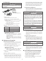
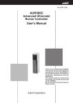
■ Labels and Sticker
1. Overview
■ Features
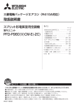
● Wiring label
This label is affixed to the C7035A and shows how
to wire it. Be sure to correctly.
• The C7035A is a flame detector that senses ultraviolet
radiation from an oil or gas burner flame.
• The C7035A conforms to UL (Underwriters
Laboratories), FM (Factory Mutual) and CSA
(Canadian Standards Association) standards.
• The C7035A can be used in ambient temperatures up
to 120 °C.
小型ウルトラビジョンC7035A1064J
注意
プロテクトリレーへの配線は青色をF端子ヘ、白色をG端子へ
接続します。逆接続の場合はUVチューブを損傷します。
Yamatake Corporation
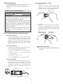
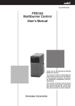
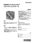
2. External Dimensions and Structure
● UV tube operating life label
This label is affixed to the UV tube.
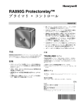
■ External Dimensions
(Unit:mm)
使用周囲温度 -40〜+120℃
129464NJ
Yamatake Corporation
110
129464NJ
UV tube
Protective
cover
57
Mounting 37
nut
24
22
UVチューブ 有効使用期限 xxxx年xx月
または使用期間 25000時間
39
● UV tube operating life sticker
This sticker is included with the C7035A. Please use
it for maintenance management.
バーナNo.
1-11BSP
Gasket
1/2-14BSP
67
Lead wires, 1800 mm long
(Insertion length)
有効使用期限
年
月
年
月
年
月
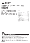
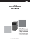
■ 129464NJ UV Tube Structure
Thermolabel
Electrode
● Thermolabel
This label is affixed to the UV tube. Keep the air
cool enough (by air purge, etc.) so that the label does
not change color from white to black. Use it as a
guide to avoid use of the tube in an environment
with excessive ambient temperature.
Socket
Quartz glass tube
Label
QR code
3. Installation Method
110, 115, 120
CAUTION
Be sure to take sufficient countermeasures if there is a
possibility that the C7035A can detect a source of
radiation other than the burner flame. Sources of
radiation (most are not relevant under normal
circumstances):
• UV rays:
Red-hot furnace wall (1371 °C or more), ignition
transformer and welding arc sparks, gas lasers,
sunlamps, disinfecting lamps, strong flashlight, etc.
• Gamma rays and X-rays:
Diffraction analyzers, electron microscopes, X-ray
machines, high-voltage vacuum switches, highvoltage capacitors, radioactive isotopes, etc.
• Countermeasures are also required in atmospheres
that obstruct the transmission of ultraviolet rays, due
to steam, soot and smoke, oil spray, dust, etc.
2
■ Temporary mounting of monitoring pipe
● Materials of monitoring pipe
• Use a monitoring pipe with a black inside wall.
Stainless steel and galvanized pipes are not good
because they reflect UV rays internally,
complicating aiming of the pipe.
● Before mounting this unit
To mount this unit correctly, thoroughly read the
instruction manuals published by burner, boiler,
and/or other equipment manufacturers. Make a
proper mounting plan based on the instruction
manuals. Appropriate mounting is the basis for good
combustion safety control.
• To avoid heat conductance to the C7035A, be
sure to use a material with low heat conductivity.
● Size of monitoring pipe
For the detector to receive the optimal amount of UV
radiation, its field of vision should be as wide as
possible. To that end, do the following:
(1) Use the widest monitoring pipe possible, at least
50A to 80A, and connect the C7035A with a
reducer.
C7035A
Tee for air purge
Temporary tack weld
Sealed adapter
(2) Make the monitoring pipe as short as possible.
(However, do not allow the ambient operating
temperature to rise above 120 °C.)
Reducer
Monitoring pipe, 50A to 80A
Pilot burner
● Mounting space
Leave sufficient space to allow easy maintenance
and inspection.
Main burner
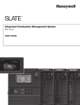
■ Wiring
● Mounting angle
• Mount the C7035A so that it monitors the burner
at an angle from above.
WARNING
• Be sure to turn the power OFF before wiring the
C7035A. Failure to do so might cause electric shock.
Handling Precautions
• If the C7035A monitors from below or in
the same horizontal plane, dust or soot
may accumulate on the monitoring window
or in the monitoring pipe, blocking the UV
rays and preventing flame detection.
CAUTION
• Carry out the wiring work in conformity with the
specifications in this document.
• To avoid electric shock or damage, connect the
power supply last.
• Mount the C7035A so that its monitoring
direction intersects the flame axis at the smallest
possible angle.
• Connect the blue signal lead from the C7035A to
terminal F and the white signal lead to terminal G of
the flame safeguard control. Incorrect wiring might
damage the UV tube.
Note
• The part of the flame that emits the most
ultraviolet radiation is the first 30 %, near the
burner nozzle.
Blue
• A small monitoring angle, relative to the flame
axis, provides the maximum overlap between
the C7035A’s monitoring area and the flame.
It therefore maximizes the amount of UV
radiation reaching the detector.
Correct: detector in good
sighting position
Correct
Flame safeguard
control
F
C7035A
White
G
Flame safeguard
control
Flame depth – shallow angle
view
Incorrect
Blue
F
White
G
C7035A
Unburned fuel
• Always keep the flame signal cables separate from
the high-voltage ignition cables and power cables.
Run the signal cables in a separate conduit.
Burner
Flame depth – perpendicular view
Incorrect: detector in poor
sighting position
3
● Wiring check
shown, within flame current/voltage range specified
for the flame safeguard control. Fluctuation within
approximately the width of the flame meter needle is
acceptable. For flame current/voltage ranges, refer to
the user’s manual for the flame safeguard control.
CAUTION
• Before turning the power supply ON, check that the
wiring to terminals F and G is correct, using the
steps below.
● Pilot burner turndown test
This test is intended to verify that the flame is
correctly passed to the main burner when this device
detects the pilot flame, even when the gas and air
pressure are at their worst levels.
Blue
F
G
White
Pin No. 3 (blue)
probe
Pin No. 1 (white)
probe
WARNING
Digital voltmeter
(commercially available tester)
• If the flame detector is set so that it detects a pilot
flame that is too small to ignite the main flame, the
C7035A will not be able to recognize (for example) a
flame failure in the main burner. In this case fuel
would continue to be supplied, causing a serious
explosion hazard. To prevent this, be sure to do the
pilot turndown test carefully.
Socket
• Check procedure
(1) Remove the UV tube from the socket.
(2) Supply power to the flame safeguard control.
(3) Measure the DC voltage in the socket with a digital
voltmeter or tester.
a. Connect the + probe to the No. 1 pin on the
socket (white lead wire).
b. Connect the – probe to the No. 3 pin on the
socket (blue lead wire).
• Reference voltage (using an Advantest TR6841
voltmeter)
Power voltage
Measured DC voltage value
85 %
Positive (150 to 180 Vdc)
100 %
Positive (160 to 210 Vdc)
110 %
Positive (180 to 230 Vdc)
• If it is necessary to do this test repeatedly,
completely shut down all equipment each time the
test is finished, and completely discharge unburned
gas or oil that has accumulated in the ducts and
combustion chamber. Failure to discharge unburned
gas may result in an explosion.
CAUTION
• This test should be done only by a trained and
experienced professional.
For details about how to carry out the pilot turndown
test, refer to the user’s manual of flame safeguard
control used with this device, as well as the
instrument manuals published by equipment
manufacturers.
Handling Precautions
• If the above measured value is negative,
the wiring for terminals F and G is
probably reversed.
● Ignition spark response test
Make sure that the flame relay (normally relay 2K)
is not affected by the spark generated by the ignition
transformer. Make sure that the C7035A does not
respond to the ultraviolet radiation from the ignition
spark.
• Mount the UV tube only after verifying by
means of this wiring check that the wiring
is correct.
■ Adjustment and inspection
After wiring, check the following:
(1) Insert the plug from the FSP136A100 analog flame
meter into the flame current measurement jack on the
amplifier of the flame safeguard control.
WARNING
• Make sure that this device does not detect ultraviolet
rays other than those of the burner flame.
(2) Light a lighter or a match in front of the UV tube to
check that the C7035A is operating properly.
For details about how to carry out the ignition spark
response test, refer to the user’s manual for the flame
safeguard control used with this device, as well as
the instrument manuals published by equipment
manufacturers.
Handling Precautions
• Before using an open flame, check that
there is no flammable gas in the vicinity.
■ Final mounting of the monitoring pipe
(3) Mount the C7035A on the monitoring pipe
temporarily.
• When the equipment is operating properly with the
specified flame voltage output after all adjustments
have been completed, turn OFF the power to the
equipment, remove the C7035A, and weld the
monitoring pipe permanently.
(4) Start the combustion of the burner.
(5) To determine the optimal monitoring position,
measure the flame current/voltage with the
FSP136A100 analog flame meter while moving the
monitoring pipe little by little in order to find a
position where the highest stable current/voltage is
• Securely mount the C7035A on the monitoring pipe
and do the final wiring carefully.
4
■ Final inspection
● UV tube replacement method
(1) Protective cover
Remove and replace the protective cover
carefully so as not to damage the UV tube. When
putting the cover on, be sure to push it fully to
the end so that it does not fall off during use.
To ensure proper burner control, do a trial run of at least
one complete operation cycle of the combustion
equipment to verify that all control operations function
correctly.
Protective cover
4. Maintenance and Inspection
CAUTION
• The effective life of the UV tube is 3 years or a total
of 25,000 hours of use after the date of inspection by
Yamatake Corporation. To be safe, be sure to
replace the UV tube within this period.
• To avoid damaging the UV tube during replacement,
be sure to hold the socket rather than the glass tube.
• After a new UV tube is removed from its package,
handle it carefully to prevent shock or impact that
could cause damage.
(2) UV tube
Hold the socket when inserting or removing the
UV tube to avoid damaging the tube. To insert,
first align the yellow mark on the UV tube with
the mark on the socket, and then push the tube
fully into the socket.
• When transporting or storing the UV tube, pack it
carefully in a secure packing box so that it is not
damaged.
Mark on the socket
■ UV tube maintenance and inspection
Yellow mark
● Flame failure test
Do this test periodically to check the function of the
UV tube. During normal burner combustion, block
the monitoring pipe window so that there is no flame
signal, or else cut off the fuel at the source to
extinguish the burner flame. Check that the flame
failure is detected and that the main valve and pilot
valve are closed.
● UV tube cleaning
Periodically clean the light-receiving glass surface of
the UV tube using the following procedure:
Handling Precautions
• Do not touch the light-receiving glass face
by hand.
(1) Remove the C7035A from the monitoring pipe.
(2) Remove the protective cover, and clean the glass
using a soft cloth.
(3) Reattach the protective cover.
(4) Put the C7035A back on the monitoring pipe.
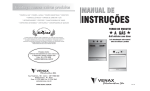
● UV tube cooling
If the ambient temperature increases above 120 °C,
the white points on the thermolabel will change
color to black. In this case, make the air cooler by
air-purging, or alternately use a sealed adapter (Part
No. 81403159) to increase the distance from the heat
source.
42 dia
39
Connection port for air-purging
Hexagonal tube R1/8
(Unit: mm)
C7035
G1
UV tube
18
G1
77
20
117
Heat resistance: to 120 °C (without air-purging)
5
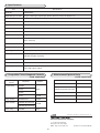
5. Specifications
Item
Specifications
Model No.
C7035A1064J
Applicable types of flame
City gas, natural gas, propane gas, butane, kerosene, heavy oil, ethylene, etc.
Power supply
From the flame safeguard control device
Allowable current
10 mAdc max.
Power consumption
250 mW max.
Ambient temperature
-40 to +120 °C
Ambient humidity
40 °C 90 % RH max.
Mass
150 g
Insulation resistance
50 MΩ min. by 500 Vdc megger (between each lead wire and the metal part of socket when the UV
tube is removed)
Allowable pressure
34.5 kPa
Vibration resistance
5 m/s2 max. (10 to 60 Hz for 2 hours each in X, Y and Z directions)
Mounting nut
1-11BSP (G1 or equivalent)
Lead wires
AWG #18 (approx. 1.2 mm2) stranded wire with heat-resistant silicone rubber insulation,
1800 mm long (blue and white)
Conduit
1/2-14BPS (G1/2 or equivalent)
Standards compliance
UL, FM and CSA
Flame signal wire
Standard: 2.0 mm2, 600 Vac cable with PVC insulation ("IV cable")
Max. length: approx. 200 m
6. Compatible Flame Safeguard Controls
(sold separately)
Flame Safeguard
Control
Protectorelay
Model No.
7. Maintenance/Optional Parts
(sold separately)
Name
Amplifier
RA890G
R4750C
built-in
Model No.
UV tube protective cover
191284
UV tube
129464NJ
(ultraviolet photoelectric tube)
R4780C
Sealed adapter
81403159
R4150
R7259B
Analog flame meter
FSP136A100
Relay module
RM7800 Series
R7849A
Flange gasket
129808
Flame module
WN200A (discontinued)
R7259B
WN210A (discontinued)
Flame relay
FRS100C
built-in
Specifications are subject to change without notice. (08)
Advanced Automation Company
1-12-2 Kawana, Fujisawa
Kanagawa 251-8522 Japan
URL: http://www.azbil.com
6
1st Edition: Issued in May 2008 (M)