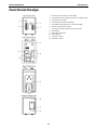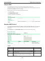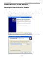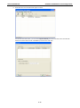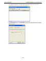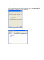
1
OnCell G3470A-LTE User’s Manual First Edition, March 2015 www.moxa.com/product © 2015 Moxa Inc. All rights reserved. OnCell G3470A-LTE User’s Manual The software described in this manual is furnished under a license agreement and may be used only in accordance with the terms of that agreement. Copyright Notice Copyright © 2015 Moxa Inc. Reproduction without permission is prohibited. Trademarks The MOXA logo is a registered trademark of Moxa Inc. All other trademarks or registered marks in this manual belong to their respective manufacturers. Disclaimer Information in this document is subject to change without notice and does not represent a commitment on the part of Moxa. Moxa provides this document as is, without warranty of any kind, either expressed or implied, including, but not limited to, its particular purpose. Moxa reserves the right to make improvements and/or changes to this manual, or to the products and/or the programs described in this manual, at any time. Information provided in this manual is intended to be accurate and reliable. However, Moxa assumes no responsibility for its use, or for any infringements on the rights of third parties that may result from its use. This product might include unintentional technical or typographical errors. Changes are periodically made to the information herein to correct such errors, and these changes are incorporated into new editions of the publication. Technical Support Contact Information www.moxa.com/support Moxa Americas Moxa China (Shanghai office) Toll-free: 1-888-669-2872 Toll-free: 800-820-5036 Tel: +1-714-528-6777 Tel: +86-21-5258-9955 Fax: +1-714-528-6778 Fax: +86-21-5258-5505 Moxa Europe Moxa Asia-Pacific Tel: +49-89-3 70 03 99-0 Tel: +886-2-8919-1230 Fax: +49-89-3 70 03 99-99 Fax: +886-2-8919-1231 Table of Contents 1. Introduction ...................................................................................................................................... 1-1 Overview ........................................................................................................................................... 1-2 Package Checklist ............................................................................................................................... 1-2 Product Features ................................................................................................................................ 1-2 Product Specifications ......................................................................................................................... 1-3 Functional Design ............................................................................................................................... 1-5 LED Indicators ............................................................................................................................ 1-6 Beeper ....................................................................................................................................... 1-7 Reset Button............................................................................................................................... 1-7 2. Getting Started.................................................................................................................................. 2-1 First-time Installation and Configuration ................................................................................................ 2-2 Step 1: Inserting a SIM Card ........................................................................................................ 2-2 Step 2: Turning on the OnCell G3470A-LTE .................................................................................... 2-2 Step 3: Connecting the OnCell G3470A-LTE to a Computer ............................................................... 2-2 Step 4: Configuring the Computer’s IP Address ............................................................................... 2-2 Step 5: Accessing the Web Console ............................................................................................... 2-3 Step 6: Establishing a Cellular Connection ...................................................................................... 2-3 Step 7: Verifying the Cellular Connection ....................................................................................... 2-4 3. Web Console Configuration ............................................................................................................... 3-1 Accessing the Web Console .................................................................................................................. 3-2 Configuration Menu Overview ....................................................................................................... 3-3 Overview ........................................................................................................................................... 3-4 Basic Settings .................................................................................................................................... 3-4 System Info Settings ................................................................................................................... 3-4 Network Settings......................................................................................................................... 3-5 Time Settings ............................................................................................................................. 3-5 Cellular Settings ................................................................................................................................. 3-6 Cellular WAN Settings .................................................................................................................. 3-6 GuaranLink ................................................................................................................................. 3-8 Auto IP Report Settings .............................................................................................................. 3-10 GPS Settings ............................................................................................................................ 3-11 Oncell Central Manager Setting ................................................................................................... 3-11 Advanced Settings ............................................................................................................................ 3-12 DHCP Server (for AP mode only) ................................................................................................. 3-12 DDNS ...................................................................................................................................... 3-13 Packet Filters ............................................................................................................................ 3-13 SNMP Agent.............................................................................................................................. 3-15 Port Forwarding ........................................................................................................................ 3-17 VPN ......................................................................................................................................... 3-18 Auto Warning Settings....................................................................................................................... 3-25 System Log .............................................................................................................................. 3-25 Syslog ..................................................................................................................................... 3-26 E-Mail ...................................................................................................................................... 3-27 Relay ....................................................................................................................................... 3-28 Trap ........................................................................................................................................ 3-29 SMS......................................................................................................................................... 3-30 Status ............................................................................................................................................. 3-31 DNS Information ....................................................................................................................... 3-31 SIM Status ............................................................................................................................... 3-31 Network Statistics ..................................................................................................................... 3-31 Routing Table ........................................................................................................................... 3-31 DHCP Client List (for AP mode only)............................................................................................. 3-32 System Log .............................................................................................................................. 3-32 Relay Status ............................................................................................................................. 3-33 DI and Power Status .................................................................................................................. 3-33 VPN Log ................................................................................................................................... 3-33 Maintenance .................................................................................................................................... 3-34 Console Settings ....................................................................................................................... 3-34 Ping ......................................................................................................................................... 3-35 Firmware Upgrade ..................................................................................................................... 3-35 Config Import Export ................................................................................................................. 3-36 Load Factory Default .................................................................................................................. 3-37 Password.................................................................................................................................. 3-37 Misc. Settings ........................................................................................................................... 3-37 Manual SMS.............................................................................................................................. 3-38 Remote SMS Control .................................................................................................................. 3-38 Save Configuration ........................................................................................................................... 3-39 Restart ............................................................................................................................................ 3-40 Logout............................................................................................................................................. 3-40 4. Software Installation and Configuration ........................................................................................... 4-1 Overview ........................................................................................................................................... 4-2 Wireless Search Utility ......................................................................................................................... 4-2 Installing the Wireless Search Utility .............................................................................................. 4-2 Configuring the Wireless Search Utility ........................................................................................... 4-5 OnCell Windows Driver Manager ......................................................................................................... 4-11 Installing OnCell Windows Driver Manager .................................................................................... 4-11 Using OnCell Windows Driver Manager ......................................................................................... 4-13 A. Supporting Information .................................................................................................................... A-1 Firmware Recovery ............................................................................................................................. A-2 DoC (Declaration of Conformity) ........................................................................................................... A-3 Federal Communication Commission Interference Statement ............................................................ A-3 R&TTE Compliance Statement ....................................................................................................... A-4 B. Dynamic Domain Name Server .......................................................................................................... B-1 C. Well-Known Port Numbers ................................................................................................................ C-1 1 1. Introduction The OnCell G3470A-LTE industrial cellular gateway is an ideal wireless solution for remote monitoring applications. With wide temperature support and power and antenna isolation design, the OnCell G3470A-LTE is rugged enough for any harsh industrial environment. The following topics are covered in this chapter: Overview Package Checklist Product Features Product Specifications Functional Design LED Indicators Beeper Reset Button OnCell 3470A-LTE Introduction Overview The OnCell G3470A-LTE industrial cellular gateway provides a higher cellular bandwidth and more reliable connection to your Ethernet network for cellular applications. With the integrated 4-port gigabit Ethernet switch and LTE support, the OnCell G3470A-LTE offers a faster cellular connection with a lower total cost of ownership. To enhance reliability, a key for industrial users, the OnCell G3470A-LTE features isolation design for both power and antenna inputs. Coupled with high-level EMS and wide-temperature support, the OnCell G3470A-LTE provides the highest level of device stability in any rugged environment. In addition, with dual SIM and dual power-input features, the OnCell G3470A-LTE supports network redundancy to ensure an uninterrupted connectivity in your applications. Package Checklist Moxa’s OnCell G3470A-LTE is shipped with the following items. If any of these items is missing or damaged, please contact your customer service representative for assistance. NOTE • OnCell G3470A-LTE • 1 GPS connector terminator • 2 2G/3G/4G omni-directional antennas, 2 dBi, SMA (male) • 5 plastic RJ45 protective caps for serial console and Ethernet ports • Quick installation guide (printed) • Warranty card The above items come with the standard OnCell G3470A-LTE model, but the package contents may vary for customized versions. Product Features • VPN support • Multiple LTE band support: EU Model: B1/B3/B7/B8/B20 US Model: B2/B4/B5/B13/B17/B25 • Universal cellular bands support for GSM/GPRS/HSPA • Built-in 4-port Gigabit Ethernet switch for local network connectivity • Virtual private responder/initiator support • Industrial-grade design: Dual power input for power redundancy Dual-SIM support for cellular connection redundancy Antenna isolation for 500V protection against radio interference Power isolation for 500V power source insulation protection -35°C to 70°C wide operating temperature (wide temperature support only applies to certain SKUs) 1-2 OnCell 3470A-LTE Introduction Product Specifications Cellular Interface Standards: GSM/GPRS/EDGE/UMTS/HSPA/LTE Band Options: OnCell G3470A-LTE-EU: • LTE 2100/1800/2600/900/800 MHz (B1/B3/B7/B8/B20) • UMTS/HSPA 2100/1900/850/800/900 MHz OnCell G3470A-LTE-US: • LTE 1900/AWS/850/700/1900 MHz (B2/B4/B5/B13/B17/B25) • UMTS/HSPA 2100/1900/AWS/850/900 MHz • Universal Quad-band GSM/GPRS/EDGE 850/900/1800/1900 MHz LTE Data Rate: • Downlink: 100 Mbps (20 MHz bandwidth), 50 Mbps (10 MHz bandwidth) • Uplink: 50 Mbps (20 MHz bandwidth), 25 Mbps (10 MHz bandwidth) HSPA Data Rate: • Downlink: Up to 42 Mbps (category 24) • Uplink: Up to 5.76 Mbps (category 6) GPRS/EDGE Data Rate: 236 kbps Downlink/Uplink (Class 10/12) LAN Interface Number of Ports: 4 Ethernet: 10/100/1000 Mbps, RJ45 connector, Auto MDI/MDIX Interface Alarm Contact: 1 relay output with current carrying capacity of 1 A @ 24 VDC Console Port: RS-232 (RJ45) Cellular Antenna Connectors: 2 SMA (female) Digital Inputs: 2 electrically isolated inputs +13 to +30 V for state “1” +3 to -30 V for state “0” GNSS: 1 SMA (female), GPS (1575.42 MHz), GLONASS (1602 MHz) LED Indicators: PWR1, PWR2, READY, FAULT, CELLULAR SIGNAL, SIM1, SIM2, 2G, 3G, 4G, GPS Ground Screw: M5 Reset Button: Power Reset/Factory Default Reset Software Network Protocols: ICMP, TCP/IP, UDP, DHCP, Telnet, DNS, SNMP, HTTP, HTTPS, SMTP, SNTP, ARP Routing/Firewall: NAT, Port Forwarding, IP/MAC/Port Filtering VPN: • Max. Tunnel Number: 5 (Responder/Initiator) • IPSec (DES, 3DES, AES, MD5, SHA-1, DH2, DH5), PSK/X.509/RSA Cellular Connectivity: GuaranLink GPS: NMEA Others: DDNS Management Software Utilities: OnCell Search Utility Configuration and Management Options: Remote SMS Control, SNMPv1/v2c/v3, Web/Telnet/Serial Console Private IP Solution: OnCell Central Manager SIM Interface Number of SIMs: 2 SIM Control: 3 V 1-3 OnCell 3470A-LTE Introduction Physical Characteristics Housing: Aluminum, providing IP30 protection Weight: 1300 g Installation: DIN-rail (default) or wall-mount (optional) Dimensions: 67 x 90.5 x 124 mm (2.6 x 3.52 x 4.83 inch) Environmental Limits Operating Temperature: Standard Models: -30 to 55°C (-22 to 131°F) Wide Temp. Models:-30 to 70°C (-22 to 158°F) Storage Temperature: -40 to 85°C (-40 to 185°F) Ambient Relative Humidity: 5 to 95% (30°C, non-condensing) Power Requirements Connector: 4-pin removable terminal block Input Voltage: 12 to 48 VDC, redundant dual inputs Power Consumption: 9.6W (12V/0.7A to 48V/0.2A) Reverse Polarity Protection: Present Standards and Certifications Safety: OnCell G3470A-LTE-US: UL 60950-1 EMC: OnCell G3470A-LTE-US: FCC Part 15 Subpart B OnCell G3470A-LTE-EU: EN 61000-6-2/-4 Radio: OnCell G3470A-LTE-US: FCC ID N7NMC7355 OnCell G3470A-LTE-EU: EN 301 489-1, EN 301 489-7, EN 301 511/4 Reliability MTBF (mean time between failures): 327,326 hrs Warranty Warranty Period: 5 years Details: See www.moxa.com/warranty ATTENTION • The OnCell G3470A-LTE is NOT a portable mobile device and should be located at least 20 cm away from the human body. • The OnCell G3470A-LTE is NOT designed for the general public. A well-trained technician should be enlisted to ensure safe deployment of OnCell G3470A-LTE units, and to establish a wireless network. 1-4 OnCell 3470A-LTE Introduction Functional Design 1. GPS antenna connector (female SMA) 2. Terminal block (two digital input and one digital relay) 3. Grounding screw (M5) 4. Terminal block (PWR1 and PWR2) 5. 2x2 MIMO antenna ports for LTE (female SMA) 6. RS-232 serial console (RJ45) 7. 10/100/1000 BaseT(X) Ethernet ports (RJ45) 8. LED display 9. DIN-rail mounting kit 10. Reset button 11. Dual SIM – SIM1 12. Dual SIM – SIM2 1-5 OnCell 3470A-LTE Introduction LED Indicators The LEDs on the front panel of the OnCell G3470A-LTE provide a quick and easy means of determining the current operational status and wireless settings. The following table summarizes how to read the device’s wireless settings from the LED displays. More information is available in Chapter 3 in the “Basic Wireless Settings” section. LED Color State Description Front Panel LED Indicators (System) PWR1 Green On Power is being supplied from power input 1 PWR2 Green On Power is being supplied from power input 2 READY Green On System startup is complete and the system is operating Blinking Device has been located by the OnCell Search Utility Off Power is off, or the system is booting up On System configuration error or a relay event has occurred Blink IP address conflict FAULT CELLULAR Red Green Off Power is off, or there is no error condition. On Number of LEDs to indicate cellular signal level when SIGNAL (3 LEDs) registered to a base station. Signal LED 1: 0 < RSSI ≤ 12 Signal LED 2: 12 < RSSI ≤ 21 Signal LED 3: 22 < RSSI ≤ 31 SIM1 SIM2 Amber Amber On/Off SIM 1 is active or inactive Blink SIM 1 is not inserted or PIN code is incorrect On/Off SIM 2 is active or inactive Blink SIM 2 is not inserted or PIN code is incorrect Registered to a base station with cellular connection in GPRS 2G Amber On 3G Amber On or EDGE mode Registered to a base station with cellular connection in UMTS or HSPA mode 4G Amber On Registered to a base station with cellular connection in LTE mode GPS Green On GPS has been located Blinking Locating GPS or less than four satellites have been located. Off GPS has not been located. LAN Port LED Indicators (Port Interface) 1000M 10/100M Green Amber On 1000Mbps link is active Blink Data is being transmitted at 1000Mbps Off 1000Mbps link is inactive On 10/100Mbps link is active Blink Data is being transmitted at 10/100Mbps Off 10/100Mbps link is inactive ATTENTION When the system fails to boot, the LEDs for STATE (Green), FAULT, and WLAN will all light up simultaneously and blink at one-second intervals. This may be due to improper operation or uncontrollable issues, such as an unexpected shutdown while updating the firmware. To recover the firmware, refer to the “Firmware Recovery” section in Chapter 6. 1-6 OnCell 3470A-LTE Introduction Beeper The beeper emits two short beeps when the system is ready. Reset Button The RESET button is located on the bottom panel of the OnCell G3470A-LTE. You can reboot the OnCell G3470A-LTE or reset it to factory default settings by pressing the RESET button with a pointed object such as an unfolded paper clip. • System reboot: Hold the RESET button down for under 5 seconds and then release. • Reset to factory default: Hold the RESET button down for over 5 seconds until the STATE LED starts blinking green. Release the button to reset the OnCell G3470A-LTE. 1-7 2 2. Getting Started This chapter explains how to install Moxa’s OnCell G3470A-LTE for the first time, and quickly set up your wireless network and test whether the connection is running well. The Function Map discussed in the third section provides a convenient means of determining which functions you need to use. The following topics are covered in this chapter: First-time Installation and Configuration Step 1: Inserting a SIM Card Step 2: Turning on the OnCell G3470A-LTE Step 3: Connecting the OnCell G3470A-LTE to a Computer Step 4: Configuring the Computer’s IP Address Step 5: Accessing the Web Console Step 6: Establishing a Cellular Connection Step 7: Verifying the Cellular Connection OnCell 3470A-LTE Getting Started First-time Installation and Configuration Before installing the OnCell G3470A-LTE, make sure that all items in the package checklist are in the box. In addition, you will need access to a notebook computer or PC equipped with an Ethernet port. The OnCell G3470A-LTE has a default IP address that you must use when connecting to the device for the first time. Step 1: Inserting a SIM Card Insert one or two 2G/3G/4G SIM cards into the SIM slots located on the bottom of the OnCell G3470A-LTE. Installing a SIM Card The SIM card slots are inside the OnCell G3470A-LTE’s housing. To install a SIM card, complete the following steps: 1. Turn off the OnCell G3470A-LTE. 2. Remove the screw to remove the SIM card slot cover. 3. Install a SIM card into a SIM card slot. Do the following: a. For SIM 1, orient the gold contacts facing down and the cut-off edge to the left. b. For SIM 2, orient the gold contacts facing up and the cut-off edge to the right. 4. Install the screw to secure the SIM card slot cover. Step 2: Turning on the OnCell G3470A-LTE Turn on the OnCell G3470A-LTE by connecting a power terminal block to a DC power source. Step 3: Connecting the OnCell G3470A-LTE to a Computer Since the OnCell G3470A-LTE supports MDI/MDI-X auto-sensing, you can use either a straight-through cable or crossover cable to connect the OnCell G3470A-LTE to a computer. If the LED indicator on the OnCell G3470A-LTE's LAN port lights up, it means a connection has been established. Step 4: Configuring the Computer’s IP Address Set an IP address on the same subnet as the OnCell G3470A-LTE. Since the OnCell G3470A-LTE’s default IP address is 192.168.127.254, and the subnet mask is 255.255.255.0, you should set the IP address of the computer to 192.168.127.xxx. NOTE After you select Maintenance > Load Factory Default and click the Submit button, the OnCell G3470A-LTE will be reset to factory default settings and the IP address will be reset to 192.168.127.254. 2-2 OnCell 3470A-LTE Getting Started Step 5: Accessing the Web Console To access the web console: 1. Open a web browser. 2. Enter http://192.168.127.254 in the address field. 3. A login screen appears. Enter the user name (the default is “admin”) and password (the default is “root”); then, click Login. NOTE Default user name and password: User Name: admin Password: root For security reasons, we strongly recommend changing the default password. To do so, select Maintenance > Password, and then follow the on-screen instructions to change the password. NOTE After you click Submit to apply changes the web page will refresh (Updated) will appear on the page and a blinking reminder will be shown on the upper-right corner of the web page: To activate the changes click Restart and then Save and Restart after you change the settings. About 30 seconds are needed for the OnCell G3470A-LTE to complete the reboot procedure. Step 6: Establishing a Cellular Connection After installing a SIM card, obtain the SIM card PIN and APN (Access Point Name) information from your service provider and configure the cellular WAN settings. To configure cellular WAN settings and establish a cellular connection: 1. Log into the web console. 2. Click Cellular Settings > Cellular WAN Settings and enter the SIM card PIN and APN values. 3. Restart the OnCell G3740A-LTE. The OnCell 3740A-LTE automatically establishes a cellular connection to the service provider. 2-3 OnCell 3470A-LTE Getting Started Step 7: Verifying the Cellular Connection You can use one of the following methods to verify the cellular connection: 1. Check the LED display. Check the SIM 1, SIM2, 2G, 3G, and 4G LEDs on the front panel. If a SIM LED is blinking, this indicates that a SIM card is not installed in the SIM slot or the SIM card PIN information is not configured in the web console. If the installed SIM card supports 3G or 4G service but only the 2G LED is turned on, this indicates that the OnCell G3470A-LTE is connected to the cellular network but is not registered for 3G or 4G service. Make sure that you enter the correct APN information in the web console. 2. Check the Overview screen in the web console. Log into the web console and display the Overview screen. Check the status for the Cellular RSSI, Cellular WAN IP address, and Cellular Mode fields to diagnose any connection problem. For Cellular RSSI (Received Signal Strength Indication), make sure that the value is above 12 RSSI in order to maintain a stable connection. If the Cellular WAN IP address is not available but the RSSI is more than 12, make sure that the APN configuration is correct. The service provider assigns a private address for the WAN IP address, which is not accessible externally. 3. Test cellular network access on your computer. For users with public SIM cards, instead of SIM cards with MDVPN service enabled, you can test the connection to the Internet on your computer (assuming that your computer is connected to an Ethernet port on the OnCell G3470A-LTE). The following shows an example configuration. Laptop IP Address: 192.168.127.10 (on the same subnet as the OnCell gateway) Laptop Subnet Mask: 255.255.255.0 (on the same subnet as the OnCell gateway) Laptop Default Gateway: 192.168.17.254 (the OnCell gateway IP address) Laptop Primary DNS Server: 8.8.8.8 (test with Google's public DNS server) Laptop Primary DNS Server: 8.8.4.4 (test with Google's public DNS server) After the configuration is complete, your computer will be able to the access the Internet. For information on testing the connection with a DHCP server, refer to Chapter 3. 2-4 3 3. Web Console Configuration This chapter describes the web console that you can use to configure your OnCell G3470A-LTE and set up a wireless network. The following topics are covered in this chapter: Accessing the Web Console Configuration Menu Overview Status DNS Information Overview SIM Status Basic Settings Network Statistics System Info Settings Routing Table Network Settings DHCP Client List (for AP mode only) Time Settings System Log Cellular Settings Cellular WAN Settings GuaranLink Auto IP Report Settings Relay Status DI and Power Status VPN Log Maintenance GPS Settings Console Settings Oncell Central Manager Setting Ping Advanced Settings Firmware Upgrade DHCP Server (for AP mode only) Config Import Export DDNS Load Factory Default Packet Filters Password SNMP Agent Misc. Settings Port Forwarding Manual SMS VPN Remote SMS Control Auto Warning Settings Save Configuration System Log Restart Syslog Logout E-Mail Relay Trap SMS OnCell 3470A-LTE Web Console Configuration Accessing the Web Console Moxa OnCell G3470A-LTE’s web browser interface provides a convenient way to modify its configuration and access the built-in monitoring and network administration functions. The recommended web browser is Microsoft® Internet Explorer 7.0 or 8.0 with JVM (Java Virtual Machine) installed. NOTE To use the OnCell G3470A-LTE’s management and monitoring functions from a PC host connected to the same LAN as the OnCell G3470A-LTE, you must make sure that the PC host and the OnCell G3470A-LTE are on the same logical subnet. The Moxa OnCell G3470A-LTE’s default IP is 192.168.127.254. Follow these steps to access the OnCell G3470A-LTE’s web-based console management interface. 1. Open your web browser (e.g., Internet Explorer) and type the OnCell G3470A-LTE’s IP address in the address field; then, press [Enter]. 2. The login page appears. Enter the password (the default username is “admin” and the default password is “root”) and click Login. It may take a few moments for the web page to load on your computer. Note that the Model name and IP address of your OnCell G3470A-LTE are both shown on the title bar of the web page. You can use this information to identify multiple OnCell G3470A-LTE units. 3. Use the menu navigation panel to access the configuration screens. In the following sections, we describe each OnCell G3470A-LTE management function in detail. For an overview of the menus, refer to the “Function Map” section of Chapter 2. NOTE The model name of the OnCell G3470A-LTE is shown as OnCell G3470A-LTE-XX, where XX indicates the country code. The country code indicates the OnCell G3470A-LTE version and which bandwidth it uses. Example figures shown in this document are for OnCell G3470A-LTE-US. The country code and model name that appear on your computer screen may be different than the one shown here. 3-2 OnCell 3470A-LTE Web Console Configuration Configuration Menu Overview Quick overview of the OnCell G3470A-LTE’s status. Basic settings for administering the OnCell G3470A-LTE. Essential settings related to establishing a cellular network. Advanced features to support additional network management and secure wired and wireless communication. Note: These advanced functions are all optional. Application-oriented device management functions to set up events, traps, and reactions via relay warning, e-mail, and SNMP notification. Note: These functions are all optional. Current status information for monitoring wired/wireless network performance, advanced services, and device management functions. Functions for maintaining the OnCell G3470A-LTE, and for diagnosing the network. On-demand functions to support the web console management operation. 3-3 OnCell 3470A-LTE Web Console Configuration Overview The Overview page provides a summary of the OnCell G3470A-LTE’s current status. The information is categorized into groups: System Info, LAN Info, and Cellular Info. Basic Settings The Basic Settings group includes the most commonly used settings required by administrators to maintain and control the OnCell G3470A-LTE. System Info Settings The System Info items, especially Device name and Device description, are displayed and included on the Overview page, in SNMP information, and in alarm emails. Setting System Info items makes it easier to identify the different OnCell G3470A-LTE units connected to your network. Field Description Default setting Device name Enter a descriptive name (up to 31 characters). OnCell This option is useful for specifying the role or application of different G3470A-LTE_[serial OnCell G3470A-LTE units. no] Device location Specify the location (up to 31 characters) of the OnCell G3470A-LTE. Device Enter a description (up to 31 characters) for the OnCell G3470A-LTE. description Device contact Enter the contact information (up to 31 characters) of the person information responsible for maintaining this OnCell G3470A-LTE. 3-4 OnCell 3470A-LTE Web Console Configuration Network Settings You can use the Network Settings screen to configure TCP/IP settings. Field Description Default setting IP address Enter the unique IP address for the OnCell G3470A-LTE. 192.168.127.254 Subnet mask Enter the subnet mask to specify the type of network to which the 255.255.255.0 OnCell G3470A-LTE is connected. Primary/Secondary Enter the IP address of the primary or secondary DNS server. DNS server After you specify a DNS server, you can access a web site by entering its URL instead of the IP address. Time Settings You can synchronize the system time on the OnCell G3470A-LTE based on an NTP (Network Time Protocol) server or user-specified date and time information. The OnCell G3470A-LTE includes the system time in system logs. NOTE The OnCell G3470A-LTE includes a built-in real time clock (RTC). We strongly recommend that you update the Current local time for the OnCell G3470A-LTE after the initial setup or a long-term shutdown, especially when the network does not have an Internet connection for accessing the NTP server or if there is no NTP server on the LAN. Field Description Default setting Current local The fields indicate the current system time on the OnCell time G3470A-LTE. Enter the date and time in the format yyyy/mm/dd hh:mm:ss To make the changes take effect, click Set Time. An “Updated” text appears to indicate that the change is complete. Note: Set the time zone before you configure the current local time. 3-5 OnCell 3470A-LTE Web Console Configuration Field Description Default setting Time zone Select a time zone from the drop-down list. The default option is GMT (Greenwich Mean Time). Note: Changing the time zone automatically changes the Current local time. We strongly recommend that you set the time zone before you set the Current local time. Daylight saving time Select Enable to activate daylight saving time (DST) or summer time. When Daylight saving time is enabled, the following fields appear: • Starts at: The date that daylight saving time begins. • Stops at: The date that daylight saving time ends. • Time offset: Indicates how many hours forward the clock should be advanced. Time server Enter the IP address or the domain name of the primary or secondary time.nist.gov 1/2 NTP server. Query period Specify how many seconds (1 to 9999) the OnCell G3470A-LTE is to 600 wait before requesting updates from the NTP server. Cellular Settings This section describes the screens you can use to configure cellular connection settings on the OnCell G3470A-LTE: • • Cellular WAN Settings–Configure this screen to establish a cellular connection. GuaranLink Settings–Use this screen to configure Moxa’s proprietary 3-tire link protection to ensure reliable network connectivity. • Auto IP Report Settings–If your service provider assigns a dynamic WAN IP address, you can configure • GPS Settings–Configure this screen to enable the built-in GPS sensor to locate your OnCell G3740A-LTE. • OnCell Central Manager Settings–Configure this screen to allow Moxa OnCell Central Manager to this screen to set the OnCell G3470A-LTE to automatically send its WAN IP address to the specified host. connect to and manage your OnCell G3740A-LTE. Cellular WAN Settings Configure the fields in the Cellular WAN Settings screen to establish a 2G/3G/4G connection to a service provider. If you install two SIM cards in the OnCell G3470A-LTE, you can select Dual SIM mode and enable the GuaranLink feature set the OnCell G3470A-LTE to regularly check connection quality and perform an automatic switchover in case a cellular connection is down. This setting ensures operator-level redundancy. 3-6 OnCell 3470A-LTE Web Console Configuration Field Description Default setting Used SIM Select a connection mode from the drop-down list. SIM 1 SIM 1 – Select this option to establish a cellular connection using the SIM card installed in the SIM 1 slot. SIM 2 – Select this option to establish a cellular connection using the SIM card installed in the SIM 2 slot. Dual SIM – Select this option to set the system to automatically establish a cellular connection using either SIM card. To ensure optimum link quality and operator-level redundancy, enable the GuaranLink feature. SIM 1/2 PIN If provided, enter the PIN (4 digits) to unlock the SIM card. Note: A SIM card becomes locked if you enter an incorrect PIN for more than three times. SIM 1/2 band Select Auto to have the OnCell device automatically negotiate with Auto the base station for the optimum cellular band frequency. Select Manual to set the OnCell device to use the selected cellular band frequency. Note: The OnCell device does not establish a cellular connection if your service provider does not support any of the bands you have selected. SIM 1/2 username If provided, enter the username for authentication with your service provider. SIM 1/2 password If provided, enter the username for authentication with your service provider. SIM 1/2 APN Your service provider may use access point network (APN) information to provide different service levels. If provided, enter the access point network (APN) information. 3-7 OnCell 3470A-LTE Web Console Configuration GuaranLink A number of factors can attribute to connection failures for cellular communications, for example, loss of cellular signal, interferences, or termination by the operator for unknown reasons. Different from the basic heartbeat function, Moxa’s proprietary GuaranLink feature enables reliable connectivity with 4-tier intelligent connection checks without sending excessive and costly cellular packets. GuaranLink Recovery Process With the GuaranLink feature, the OnCell G3470A-LTE automatically tries to re-establish a connection when a connection failure has occurred. The OnCell G3470A-LTE performs one of the following actions, depending on the number of enabled SIM cards: • One SIM card – Resets the cellular module without rebooting the device to force negotiation between the OnCell G3470A-LTE and the base station. • Dual SIM cards – Reset the cellular module without rebooting the device and establish a cellular connection using the second SIM card account. GuaranLink Settings In the navigation panel, click Network Settings > GuaranLink Settings to display the configuration screen. The following table describes the fields. 3-8 OnCell 3470A-LTE Web Console Configuration Field Description Default setting GuaranLink Select Enable to activate the GuaranLink feature. Disable For operator-level redundancy, enable GuaranLink with Dual SIM mode to set the OnCell G3470A-LTE to regularly check connection quality and perform an automatic switchover in case a cellular connection is down. Select Disable to deactivate the GuaranLink feature. Register to network This field is used for ISP initial connection check. timeout Enter the time (10 – 600 minutes) the OnCell G3470A-LTE is to wait 10 before terminating connection to an ISP and starts the GuaranLink recovery process. Data session retry Enter the number of times (1-5) the OnCell G3470A-LTE is to count request for an IP address from the ISP. 3 If the OnCell G3470A-LTE fails to obtain an IP address after 3 minutes, it starts the GuaranLink recovery process. DNS/Ping remote This field is used for packet-level and transmission connection host 1/2 checks. Enter the IP address or domain name of a remote host for Ping or DNS lookup test. ISP initial Select Enable to set the OnCell G3470A-LTE to complete the connection check registration process to a base station before the timeout specified in Disable the Register to network timeout field. If the OnCell G3470A-LTE fails to register to the base station within the timeout period, it starts the GuaranLink recovery process. Select Disable to allow the OnCell G3470A-LTE to wait until base station registration is successful. Cellular connection Depending on your ISP, cellular connection is terminated if there is Disable alive check no active data transmission for a period of time. Select Enable to set the OnCell G3470A-LTE to keep the cellular connection alive by performing a DNS lookup or remote host Ping if no data is transmitted within the timeout period. If the connection check fails after the number of retries specified in the Cellular connection alive retry count field, the OnCell G3470A-LTE starts the GuaranLink recovery process. Cellular connection Enter the time (between 1 to 600 minutes) the OnCell G3470A-LTE 5 alive check interval is to wait before performing a connection check. Cellular connection Enter the number the OnCell G3470A-LTE is to try the connection alive check retry check in 15 seconds. count If the connection check fails, the OnCell G3470A-LTE starts the Packet-level Select Enable to check whether the cellular network is accessible connection check using DNS lookup and remote host ping, regardless of any existing 5 GuaranLink recovery process. Disable data transmission. If the connection check fails after the number of retries specified in the Packet-level connection check retry count field, the OnCell G3470A-LTE starts the GuaranLink recovery process. Packet-level Select one of the following options to determine if the connection connection check check is successful: action • DNS and Ping – Response from both the DNS server and remote host. • DNS or Ping – Response from either the DNS server or the remote host. 3-9 DNS and Ping OnCell 3470A-LTE Web Console Configuration Field Description Default setting Packet-level Enter the time (between 1 to 600 minutes) the OnCell G3470A-LTE 5 connection check is to wait before performing a connection check. interval Packet-level Enter the number the OnCell G3470A-LTE is to try the connection connection check check in 15 seconds before re-establishing the connection. 3 retry count Transmission If a remote system regularly monitors connection to the OnCell connection check G3470A-LTE, select Enable to set the OnCell G3470A-LTE to receive Disable polling information from the remote system at regular intervals. If no polling information is received within the timeout period, the OnCell G3470A-LTE starts the GuaranLink recovery process. Transmission Enter the time (between 1 to 600 minutes) the OnCell G3470A-LTE 5 connection alive is to wait for polling information from a remote system before check interval starting the GuaranLink recovery process. Auto IP Report Settings In MDVPN (mobile data virtual private network) applications where service providers set up private VPNs for enterprise customers, a cellular gateway must be assigned IP address that is visible to a remote host in a central office. In cases where a service provider assigns dynamic IP addresses, you can configure the Auto IP Report Settings screen to set the OnCell G3470A-LTE to regularly send its WAN IP address to a remote host. The following table describes the fields. Field Description Auto IP report to Enter the IP address of a remote host to which the OnCell Default setting host G3470A-LTE is to send the WAN IP address information. Report to UDP port Enter the listing port number on the remote host. 63100 Report period 99 Enter the number of minutes the OnCell G3470A-LTE is to wait before sending WAN IP address information. The following figure shows the Auto IP report format. Auto IP Report Format “Moxa”, 4 bytes Info[0] Info[1] ... Info[n] Info [n] Field ID Length Data Length a 1 Variable, Length is “Length Field” ID List ID Value Description Length Note 1 Server Name Variable ASCII char 2 Hardware ID 2 Little-endian 3 MAC Address 6 6-byte MAC address. If the MAC address is “00-90-E8-01-02-03” then MAC[0] is 0, MAC[1] is 0x90(hex), MAC[2] is 0xE8(hex), etc. 3-10 OnCell 3470A-LTE Web Console Configuration 4 Serial Number 4, DWORD Little-endian 5 IP Address 4, DWORD Little-endian (LAN IP) 9 AP ID 4, DWORD Little-endian 10 IP Address2 4, DWORD Little-endian (WAN IP) 11 Signal Level 1 Unsigned char 12 RSSI 1 Unsigned char AP ID & Hardware ID Mapping Table AP ID Hardware ID Product 0x80005260 0x5061 5004-HSPA 0x80005260 0x5061 5104-HSPA GPS Settings You can activate the GPS module function under GPS Settings, and then enable GPS serial mode under Real COM mode or Reverse Real COM mode. OnCell Central Manager provides the current location, including latitude and altitude information. Setting Description GPS Activate GPS module Disable Enable Enable GPS Serial Mode Disable Use OCM to get the location information under Real COM or Real COM Serial Operation mode Factory Default Reverse Real COM serial mode. TCP alive check time This field specifies how long the OnCell G3470A-LTE will wait 7 min for a response to “keep alive” packets before closing the TCP connection. The OnCell G3470A-LTE checks the connection status by sending periodic “keep alive” packets. If the remote host does not respond to the packet within the time specified in this field, the OnCell G3470A-LTE will force the existing TCP connection to close. For socket and device control modes, the OnCell G3470A-LTE will listen for another TCP connection from another host after closing the connection. If TCP alive check time is set to 0, the TCP connection will remain open and will not send any “keep alive” packets. Oncell Central Manager Setting For Oncell Central Manager settings, refer to the OnCell Central Manager V2 software user’s guide, which can be downloaded from www.moxa.com. 3-11 OnCell 3470A-LTE Web Console Configuration Advanced Settings Several advanced functions are available to increase the functionality of your OnCell G3470A-LTE and wireless network system. The DHCP server helps you deploy wireless clients efficiently. Packet filters provide security mechanisms, such as firewalls, in different network layers. Moreover, SNMP support can make network management easier. DHCP Server (for AP mode only) DHCP (Dynamic Host Configuration Protocol) is a networking protocol that allows administrators to assign temporary IP addresses to network computers by “leasing” an IP address to a user for a limited amount of time, instead of assigning permanent IP addresses. The OnCell G3470A-LTE can act as a DHCP server and assign IP addresses to your DHCP clients by responding to DHCP requests from the clients. The IP-related parameters you set on this page will also be sent to the client. You can also assign a static IP address to a specific client by entering its MAC address. The OnCell G3470A-LTE provides a Static DHCP mapping list with up to 16 entities. Be reminded to check the Active check box for each entity to activate the setting. You can check the IP assignment status in the DHCP Client List screen (click Status > DHCP Client List). The following table provides the field descriptions. Field Description Default setting DHCP server Select Enable to set the OnCell G3470A-LTE as a DHCP server. Disable Select Disable to set the OnCell G3470A-LTE as a DHCP client. Default gateway Enter the IP address of the default gateway that connects to an outside network. Subnet mask Enter the subnet mask to specify the type of network for the DHCP clients. Primary/Secondary Enter the IP address of the primary or secondary DNS server. DNS server After you specify a DNS server, you can access a web site by entering its URL instead of the IP address. Start IP address Enter the starting IP address in the IP address pool. Maximum number Enter the number (between 1 and 999) of IP address to assign to of users DHCP clients. 3-12 OnCell 3470A-LTE Web Console Configuration Field Description Default setting Client lease time Enter the lease time (between 2 and 14400 minutes) for an assigned IP address. The IP address expired after the lease time. DDNS If a DHCP server assigns an IP address to the OnCell G3470A-LTE, you can configure dynamic DNS (DDNS) setting on the OnCell G3470A-LTE to allow remote servers to access the OnCell G3470A-LTE using its domain name instead of IP address. For more information on DDNS, see Appendix C. Click Advanced Settings > DDNS to display the configuration screen. The following table provides the field descriptions. Field Description Default setting Enable Select Enable to activate the DDNS feature. Disable Service provider Select an option from the drop-down list. Host name Enter the host name you created with the service provider. Username Enter the username for update authentication. Password Enter the password for update authentication. Packet Filters The OnCell G3470A-LTE includes various filters for IP-based packets going through LAN and WLAN interfaces. You can set these filters as a firewall to help enhance network security. MAC Filter The OnCell G3470A-LTE’s MAC filter is a policy-based filter that can allow or filter out IP-based packets with specified MAC addresses. The OnCell G3470A-LTE provides 8 entities for setting MAC addresses in your filtering policy. Remember to check the Active check box for each entity to activate the setting. Field Description Default setting Enable Select Enable to enable MAC filtering. Disable Policy Select Accept to allow packets that meet the specified criteria. Drop Select Drop to deny packets that meet the specified criteria. 3-13 OnCell 3470A-LTE Web Console Configuration ATTENTION Be careful when you enable the filter function: Drop + “no entity on list is activated” = all packets are allowed Accept + “no entity on list is activated” = all packets are denied IP Protocol Filter The OnCell G3470A-LTE’s IP protocol filter is a policy-based filter that can allow or filter out IP-based packets with specified IP protocol and source/destination IP addresses. The OnCell G3470A-LTE provides 8 entities for setting IP protocol and source/destination IP addresses in your filtering policy. Four IP protocols are available: All, ICMP, TCP, and UDP. You must specify either the Source IP or the Destination IP. By combining IP addresses and netmasks, you can specify a single IP address or a range of IP addresses to accept or drop. For example, “IP address 192.168.1.1 and netmask 255.255.255.255” refers to the sole IP address 192.168.1.1. “IP address 192.168.1.1 and netmask 255.255.255.0” refers to the range of IP addresses from 192.168.1.1 to 192.168.255. Remember to check the Active check box for each entity to activate the setting. Field Description Default setting Enable Select Enable to enable IP protocol filtering. Disable Select Accept to allow packets that meet the specified criteria. Drop Policy Select Drop to deny packets that meet the specified criteria. ATTENTION Be careful when you enable the filter function: Drop + “no entity on list is activated” = all packets are allowed. Accept + “no entity on list is activated” = all packets are denied. TCP/UDP Port Filter The OnCell G3470A-LTE’s TCP/UDP port filter is a policy-based filter that can allow or filter out TCP/UDP-based packets with a specified source or destination port. The OnCell G3470A-LTE provides 8 entities for setting the range of source/destination ports of a specific protocol. In addition to selecting TCP or UDP protocol, you can set either the source port, destination port, or both. The end port can be left empty if only a single port is specified. Of course, the end port cannot be larger then the start port. The Application name is a text string that describes the corresponding entity with up to 31 characters. Remember to check the Active check box for each entity to activate the setting. 3-14 OnCell 3470A-LTE Web Console Configuration Field Description Default setting Enable Select Enable to enable TCP/UDP port filtering. Disable Select Accept to allow packets that meet the specified criteria. Drop Policy Select Drop to deny packets that meet the specified criteria. ATTENTION Be careful when you enable the filter function: Drop + “no entity on list is activated” = all packets are allowed Accept + “no entity on list is activated” = all packets are denied SNMP Agent The OnCell G3470A-LTE supports SNMP V1/V2c/V3. SNMP V1 and SNMP V2c use a community string match for authentication, which means that SNMP servers access all objects with read-only or read/write permissions using the community string public/private (default value). SNMP V3, which requires you to select an authentication level of MD5 or SHA, is the most secure protocol. You can also enable data encryption to enhance data security. The OnCell G3470A-LTE’s MIB can be found in the software CD and supports reading the attributes via SNMP. (Only get method is supported.) SNMP security modes and security levels supported by the OnCell G3470A-LTE are shown in the following table. Select the security mode and level that will be used to communicate between the SNMP agent and manager. Protocol Setting on Authenticati Data Version on Type Encryption No Use a community string match for authentication No Use a community string match for authentication No Use account with admin or user to access objects No Provides authentication based on HMAC-MD5, or UI web Method page SNMP V1, V2c Community V1, V2c Read string Community V1, V2c Community Write/Read string Community SNMP V3 No-Auth No MD5 or SHA Authenticatio n based on HMAC-SHA algorithms. 8-character passwords are the MD5 or SHA minimum requirement for authentication. MD5 or SHA Authenticatio Data Provides authentication based on HMAC-MD5 or n based on encryption HMAC-SHA algorithms, and data encryption key. MD5 or SHA key 8-character passwords and a data encryption key are the minimum requirements for authentication and encryption. 3-15 OnCell 3470A-LTE Web Console Configuration The following parameters can be configured on the SNMP Agent page. A more detailed explanation of each parameter is given below the following figure. Field Description Default setting Enable Select Enable to activate SNMP agent. Disable Remote Select Enable to allow remote management via SNMP agent. Disable Enter the community string or password (up to 31 characters public management Read community long) for an SMNP agent to access objects with read-only permission. Write community Enter the community string or password (up to 31 characters private long) for an SMNP agent to access objects with read-write permission. SNMP agent Select the SNMP protocol version used to manage the OnCell version G3470A-LTE. V1, V2c Admin Select No Auth to use an administrator account to access objects No Auth authentication without authentication. type Select MD5 to authenticate using HMAC-MD5 algorithms where the minimum requirement is to use an 8-character password. Select SHA to authenticate using HMAC-SHA algorithms where the minimum requirement is to use an 8-character password. Admin privacy type Select Disable for no data encryption. Select DES to use DES-based data encryption. Select AES to use AES-based data encryption. Privacy key Enter the key (up to 63 characters) for data encryption. Private MIB The object ID (OID) is the enterprise value for the OnCell information Device G3470A-LTE. This value is not configurable. object ID 3-16 Disable OnCell 3470A-LTE Web Console Configuration Port Forwarding You can configure port forwarding settings on the OnCell G3470A-LTE to redirect specific packets from a remote host on the WAN to a server on the LAN. This feature hides the IP address of a local server and prevents remote hosts from accessing the local server directly. The OnCell G3470A-LTE filters out unrecognized packets to protect your LAN network when computers connected to the OnCell G3470A-LTE are not visible to the WAN. NOTE You can make LAN computers accessible from the Internet by enabling Virtual Server. You can also configure port forwarding on the OnCell G3470A-LTE to redirect traffic to a specific port on a LAN computer. To access the Port Forwarding screen, click Advanced Settings Port Forwarding. The Oncell G3470A-LTE supports a total of 32 port forwarding rules. The following table includes the field descriptions. Field Description Factory Default Enable Select Enable to activate the port forwarding feature. Disable Active Select this check box to activate the port forwarding entry. Protocol Select an option from the drop-down list. Public Port Enter the public port number. Make sure that the port number specified is not already used by OP modes. Internal IP Enter the IP address of a LAN device to receive the redirected traffic. Internal Port Enter the port number on a LAN device to which to redirect traffic. 3-17 OnCell 3470A-LTE Web Console Configuration VPN Computers that are part of a virtual private network (VPN) use a second, “virtual” IP address to connect to the Internet. Instead of running across a single private network, some of the links between nodes that are part of a VPN use open network connections or virtual circuits on a larger network, such as the Internet. With the help of VPNs, cellular devices acting as a VPN client can initiate a connection with a VPN server. Once the connection is established, cellular devices can communicate with other network devices on the same private network. The following figure shows a network example. OnCell G3470A-LTE VPN Feature Overview • The OnCell G3470A-LTE IPSec provides security in a network with Gateway-to-gateway topology as illustrated in the following figure. • The OnCell G3470A-LTE initiates a VPN connection to a VPN Server. • The OnCell G3470A-LTE IPSec operates in Tunnel mode with IPsec VPN tunnel. Manual Key/ESP, IKE/PSK DES/3DES/AES128 encryption MD5/SHA1 authentication • IPsec NAT traversal and PFS (Perfect Forwarding Secrecy). 3-18 OnCell 3470A-LTE Web Console Configuration IPSec Settings You can enable or disable the IPSec and NAT traversal functions and configure up to five VPN tunnels in the IPSec Settings screen (click Advanced Settings > VPN > IPSec Settings). The following table provides the field descriptions. Field Description Factory Default IPSec setting enable Select Enable to activate the IPSec feature. Disable NAT Traversal Select Enable to activate the NAT traversal feature that allows Disable IPSec traffic to traverse through NAT-enabled devices. Make sure that the remote VPN device supports this feature. Action Click Edit to configure a VPN tunnel. Click Delete to remove the selected VPN tunnel. Configuring a VPN Tunnel To configure a VPN tunnel, click Edit in the IPSec Settings screen. 3-19 OnCell 3470A-LTE Web Console Configuration The following table provides the field descriptions. Field Description Factory Default IPSec enable Select Enable to activate the VPN tunnel. Disable Connection name Enter a descriptive name for the VPN tunnel. Connection type Select one of the following connection types: • Site-to-Site – Select this option to create a VPN tunnel for • Site-to-Site(any) – Select this option to create a VPN Site-to-Site static local and remote subnets. tunnel between a static local subnet and a dynamic remote subnet. Startup mode Select Start in Initial to set the OnCell G3470A-LTE to initiate Start in Initial a connection with the remote VPN gateway. Select Wait for Connecting to set the OnCell G3470A-LTE to wait for a remote VPN gateway to initiate a connection. Remote VPN gateway Enter the WAN IP address of the remote VPN gateway. Local network Enter the remote VPN server subnet IP of the local network. Local netmask Enter the remote VPN server subnet netmask of the local Local ID Enter an ID (IP/FQDN/User_FQDN) to identify and authenticate network. the local VPN gateway. Remote network Enter the remote VPN server subnet IP of the remote network. Remote netmask Enter the remote VPN server subnet netmask of the remote network. Remote ID Enter an ID (IP/FQDN/User_FQDN) to identify and authenticate the remote VPN endpoint. Key Exchange (Phase1) Operation mode Select main mode or aggressive mode to configure the Main standard negotiation parameters for IKE Phase 1 of the VPN Tunnel. Authentication mode Select Pre-shared key, RSA Signature or X.509 Pre-shared key authentication mode to for phase 1 key exchange. The configuration fields vary depending on the authentication mode you select. For information on configuring each authentication mode, refer to the following sections. Encryption algorithm Select the DES, 3DES or AES128 algorithm for the VPN ISAKMP DES phase 1 encryption mode. Hash algorithm Select the MD5 or SHA-1 VPN key exchange phase 1 hash MD5 mode. DH group Select the DH-2(1024) or DH-5(1536) VPN key exchange DH-2 phase 1 Diffie-Hellman group. As the Diffie-Hellman Group number increases, the higher the level of encryption implemented for PFS. Negotiation time The number of allowed reconnect times when startup mode is 0 initiated. If the number is 0, this tunnel will always try connecting to the remote gateway when the VPN tunnel is not created successfully. IKE life time Enter the number of minutes for the VPN IKE SA phase 1 60 Lifetime. This is the period of time to pass before establishing a new IPSec security association (SA) with the remote endpoint. Rekey expire time Enter the number of minutes for the Start to Rekey before IKE 9 lifetime expired. Rekey fuzz percent The rekey expire time will change randomly to enhance the security. Rekey fuzz percent is the maximum random change 3-20 100% OnCell 3470A-LTE Field Web Console Configuration Description Factory Default margin of the Rekey expire time. 100% means the rekey expire time will not change randomly. Data Exchange (phase2) Perfect forward secrecy Enable or disable the Perfect Forward Secrecy. PFS is an Disable additional security protocol. SA life time Enter the number of seconds for the VPN ISAKMP phase 2 480 Lifetime. This is the period of time to pass before establishing a new IPSec security association (SA) with the remote endpoint. Encryption algorithm Select the DES, 3DES, or AES128 algorithm for the VPN DES ISAKMP phase 1 encryption mode. Hash algorithm Select the MD5 or SHA-1 VPN ISAKMP phase 1 authentication MD5 mode. Dead Peer Detection DPD action When you enable the Dead Peer Detection (DPD) feature, the Disable OnCell G3470A-LTE performs one of the following actions when connection to a remote IPSec tunnel is down: • Hold: Keep the VPN tunnel • Clear: Clear the VPN tunnel • Restart: Re-establish the VPN tunnel on Start in Initial mode. • Restart by Peer: Re-establish the VPN tunnel on Wait for connecting mode. DPD delay The period of dead peer detection messages. 30 DPD timeout Timeout to check if the connection is alive or not. 120 Configuring Pre-shared Key Settings To configure pre-shared key authentication mode in phase 1 key exchange, in the Tunnel settings screen, select Pre-shared key from the Authentication mode drop-down list. Then, enter a key in the text field. Make sure that you configure the same key on the OnCell G3470A-LTE and the remote VPN gateway. Configuring RSA Signature Settings To configure RSA signature settings, complete the following steps: 1. In the Tunnel Settings screen, select RSA Signature from the Authentication mode drop-down list. 2. Generate or import a local private key. Perform one of the following actions: • Click Generate Local Private Key. The OnCell G3470A-LTE creates a private key and displays the key information in the Local private key field. • Click Import Local Private Key and select a key file to import. After the OnCell G3470A-LTE successfully imports the selected key, the system displays the key information in the Local private key field. 3. Generate or import a remote private key. Perform one of the following actions: • Click Generate Remote Public Key. The OnCell G3470A-LTE creates a public key and displays the key information in the Remote public key field. • Click Import Remote Public Key and select a key file to import. After the OnCell G3470A-LTE successfully imports the selected key, the system displays the key information in the Remote public key field. 3-21 OnCell 3470A-LTE Web Console Configuration The following figure shows the certificate generation and certificate export/import example. Device A Device B 1. Generate Root CA 1. Generate Root CA 2. Generate Local Certificate 2. Generate Local Certificate 3. Click PKCS#12 Export to export the local 3. Click PKCS#12 Export to export the certificate (local_CA_A.p12) local certificate (local_CA_B.p12) 4. Click Certificate Export to export the 4. Click Certificate Export to export the local certificate file (local_CA_A.pem) local certificate file (local_CA_B.pem) 5. Click VPN > X.509 >Local Certificate 5. Click VPN > X.509 >Local Upload and import the local certificate Certificate Upload and import the (local_CA_A.p12). local certificate (local_CA_B.p12). 6. Click VPN > X.509 > Remote 6. Click VPN > X.509 > Remote Certificate Upload to import the remote Certificate Upload to import the certificate (local_CA_B.pem). remote certificate (local_CA_A.pem). X.509 Settings NOTE Before you configure X.509 settings, make sure that you have imported local and remote certificates in the Local/Remote Certificate Upload screen (click Advanced Settings > VPN > X.509 Certificate > Local/Remote Certificate Upload). In the Tunnel Settings screen, select X.509 from the Authentication mode drop-down list and select a certificate from the Local certificate and Remote certificate drop-down lists. Certificate Generation X.509 is a digital certificate method commonly used for IPSec authentication. You can generate a self-signed root CA or local certificate on the OnCell G3470A-LTE and import or export the certificate on a remote VPN gateway. To display the Certificate Generation screen, click Advanced Settings > VPN > X.509 Certificate > Certificate Generation. 3-22 OnCell 3470A-LTE Web Console Configuration To generate a root CA certificate, complete the following steps: 1. In the Certificate Generation screen, enter information in the fields under Root Certificate Generation. Field Description Certificate days Enter the number of days the certificate is valid for. Certificate password Enter a password to create a password-protected certificate. Country name Enter the country. State or province name Enter the state or the province. Locality name Enter the city. Organization name Enter the name of the organization. Organization unit name Enter the unit or section in the organization. Common name Enter a name (such as a server name or your name). Email address Enter an email address. 2. Click Generate Root CA. After you have generated the root CA certificate, generate a local certificate and export the key files. Complete the following steps: 1. In the Certificate Generation screen, enter information in the fields under Local Certificate Settings. Field Description Certificate days Enter the number of days the certificate is valid for. Certificate password Enter a password to create a password-protected certificate. Organization unit name Enter the unit or section in the organization. Common name Enter a name (such as a server name or your name). Email address Enter an email address. 2. Click Generate Local Certificate. 3. Click Certificate Export to export the public key file for the certificate that you import on a remote VPN gateway. 4. Click PKCS#12 Export to export the private key file for local certificates on the OnCell G3470A-LTE. You can import the local certificate in the Local Certificate Upload screen. 3-23 OnCell 3470A-LTE Web Console Configuration Local Certificate Upload If you configure X.509 authentication mode for VPN tunnel setup, you must import a local certificate on the OnCell G3470A-LTE. You can add or delete a local certificate in the Local Certificate Upload screen. 1. Click Advanced Settings > VPN > X.509 Certificate > Local Certificate Upload. 2. In the PKCS#12 upload field, click Browse to select a local certificate. 3. In the Import password field, enter the certificate password. 4. Click Import. NOTE You can generate a local certificate in the Certificate Generation screen. Remote Certificate Upload You can add or delete a certificate from the remote VPN gateway in the Remote Certificate Upload screen. 1. Click Advanced Settings > VPN > X.509 Certificate > Remote Certificate Upload. 2. In the Remote certificate upload field, click Browse to select a local certificate. 3. Click Import. 3-24 OnCell 3470A-LTE Web Console Configuration Auto Warning Settings Since industrial-grade devices are often located at the endpoints of a system, these devices will not always know what is happening elsewhere on the network. This means that these devices, including wireless APs or clients, must provide system maintainers with real-time alarm messages. Even when system administrators are out of the control room for an extended period, they can still be informed of the status of devices almost instantaneously when exceptions occur. In addition to logging these events, the OnCell G3470A-LTE supports different approaches to warn engineers automatically, such as SNMP trap, e-mail, and relay output. It also supports two digital inputs to integrate sensors into your system to automate alarms by email and relay output. System Log System Log Event Types Detail information for grouped events is shown in the following table. You can select the Enable log check box to enable the selected event types. All default values are enabled (checked). The log for system events can be seen in Status > System Log. The following table describes the types of system logs. System-related events System restart (warm start) Event is triggered when… The OnCell G3470A-LTE is rebooted, such as when its settings are changed (IP address, subnet mask, etc.). Network-related events Event is triggered when… LAN link on The LAN port is connected to a device or network. LAN link off The port is disconnected (e.g., the cable is pulled out, or the opposing device shuts down). Client joined/ left A wireless client is associated or disassociated. (for AP mode) WLAN connected to AP The OnCell G3470A-LTE is associated with an AP. (for Client mode) WLAN disconnected The OnCell G3470A-LTE is disassociated from an AP. (for Client mode) Config-related events Event is triggered when… Configuration Changed A configuration item has been changed. Configuration file import via Web Console The configuration file is imported to the OnCell G3470A-LTE. Console authentication failure An incorrect password is entered. Firmware upgraded The OnCell G3470A-LTE’s firmware is updated. Power events Event is triggered when… Power 1/2 transition (On -> Off) The OnCell G3470A-LTE is powered down in PWR1/2. Power 1/2 transition (Off -> On) The OnCell G3470A-LTE is powered via PWR1/2. DI events Event is triggered when … DI1/2 transition (On -> Off) Digital Input 1/2 is triggered by on to off transition. DI1/2 transition (Off -> On) Digital Input 1/2 is triggered by off to on transition. 3-25 OnCell 3470A-LTE Web Console Configuration Syslog This function provides the event logs for the Syslog server. The function supports up to three configurable Syslog servers and Syslog server UDP port numbers. When an event occurs, the event will be sent as a Syslog UDP packet to the specified Syslog servers. Syslog Event Types Detail information for the grouped events is shown in the following table. You can the Enable log check box to enable the selected event types. All default values are enabled (checked). For information on the event types, refer to the System Log Event Types section. Syslog Server Settings You can configure the parameters for your Syslog server on the Syslog Server Settings screen. Field Description Syslog server 1/2/3 Enter the IP address of the 1st/ 2nd/ 3rd Syslog Server Factory Default Syslog port Enter the UDP port for the syslog server. 3-26 514 OnCell 3470A-LTE Web Console Configuration E-Mail E-Mail Event Types Select the Active checkbox to enable an event item. By default, all values are deactivated (unchecked). E-mail Server Settings The E-mail server settings determine how e-mail warnings are sent for system and serial port events. You may configure up to 4 e-mail addresses to receive automatic warnings. 3-27 OnCell 3470A-LTE Web Console Configuration ATTENTION Consult your Network Administrator or ISP for the proper mail server settings. The Auto warning function may not work properly if it is not configured correctly. The OnCell G3470A-LTE’s SMTP AUTH supports LOGIN, PLAIN, and CRAM-MD5 (RFC 2554). Mail server Setting Description Factory Default Mail server This field is for your mail server’s domain name or IP address. . None User name Setting Description Factory Default User name This field is for your mail server’s user name, if required. None Setting Description Factory Default Password This field is for your mail server’s password, if required. None Password From e-mail address Setting Description Factory Default From e-mail address This is the e-mail address from which automatic e-mail None warnings will be sent. To e-mail address 1 to 4 Setting Description To e-mail address This is the e-mail address or addresses to which the automatic None Factory Default 1 to 4 e-mail warnings will be sent. Relay Relay Event Types Select Active to enable the event types. For information on the event types, refer to the System Log Event Types section. 3-28 OnCell 3470A-LTE Web Console Configuration Trap Traps can be used to signal abnormal conditions (notifications) to a management station. This trap-driven notification can make your network more efficient. Because a management station usually takes care of a large number of devices that have a large number of objects, it will be overloading for the management station to poll or send requests to query every object on every device. It would be better if the managed device agent could notify the management station by sending a message known as a trap for the event. Trap Event Types SNMP Trap Receiver Settings SNMP traps are defined in SMIv1 MIBs (SNMPv1) and SMIv2 MIBs (SNMPv2c). The two styles are basically equivalent, and it is possible to convert between the two. You can set the parameters for SNMP trap receivers through the web page. Field Description Default setting Trap version Select the SNMP version for SNMP traps. V1 Trap server Enter the IP address or domain name of the SNMP trap server. IP/name Trap community Enter the community string or password (up to 31 characters) for alert authentication. 3-29 OnCell 3470A-LTE Web Console Configuration SMS SMS Event Types Select Active to enable the event types. For information on the event types, refer to the System Log Event Types section. SMS Alert Settings You can set the OnCell G3470A-LTE to send SMS notifications to up to four phone numbers and select a message encoding format in the SMS Alert Settings screen. Field Description To phone number Enter the phone numbers to which the OnCell G3470A-LTE 1/2/3/4 sends SMS notifications. Encode format Select an encoding format from the drop-down list. • Factory Default Text ASCII (7 bits) – Encode SMS messages in 7-bit format (160 bytes per packet). 3-30 Text ASCII (7 bits) OnCell 3470A-LTE Web Console Configuration Status DNS Information The DNS information screen displays the DNS server to which the OnCell G3470A-LTE is connected and the DNS server information. SIM Status The SIM Status screen displays the current SIM card in use and the status of the SIM cards installed in the OnCell G3470A-LTE. Network Statistics The Network Statistics screen displays information on each interface. Routing Table The Routing Table screen displays the list of routes the OnCell G3470A-LTE uses to send packets on each interface. Possible flags include: U: route is up +: default gateway D: route is down T: static route G: use gateway H: target is a host 3-31 OnCell 3470A-LTE Web Console Configuration DHCP Client List (for AP mode only) The DHCP Client List shows all the clients that require and have successfully received IP assignments. You can click the Refresh button to refresh the list. You can press Select all button to select all content in the list for further editing. System Log Triggered events are recorded in System Log. You can export the log contents to an available viewer by clicking Export Log. You can use the Clear Log button to clear the log contents and the Refresh button to refresh the log. 3-32 OnCell 3470A-LTE Web Console Configuration Relay Status The status of user-configurable events can be found under Relay Status. If an event is triggered, the event is included on this list. After you have addressed an event, click Acknowledge Event. DI and Power Status You can view the digital input (DI) and power input information in the DI and Power Status screen. VPN Log The VPN Log screen displays VPN connection information. 3-33 OnCell 3470A-LTE Web Console Configuration VPN System log The following table lists the system logs for the VPN feature. [VPN name] indicates the name of the VPN tunnel you have created on the OnCell G3470A-LTE. System log Description [VPN name] mismatch of PSK Pre-shared key mismatch. [VPN name] Phase 1 start VPN tunnel phase 1 start. [VPN name] Phase 1 pass VPN tunnel phase 1 pass. [VPN name] Phase 2 start VPN tunnel phase 2 start. [VPN name] Phase 2 pass VPN tunnel phase 2 pass. [VPN name] received Delete ISAKMP SA Remote VPN tunnel request to delete ISAKMP SA. [VPN name] no Preshared Key Found No pre-shared key is found. [VPN name] policy doesn't allow PRESHARED KEY The encryption algorithm does not allow pre-shared key. [VPN name] policy doesn't allow RSASIG VPN encrypt algorithm does not allow RSA or X.509. [VPN name] DPD timeout - declaring peer dead No response from a peer. PDP timeout. [VPN name] DPD: Hold connection Clear the remote VPN SA and keep the peer routing table status. [VPN name] DPD: Clearing Connection Clear the remote VPN SA and peer routing table status. [VPN name] DPD: Restarting Connection Renegotiate VPN SA immediately. [VPN name] encrypt alg is different VPN encryption mismatch. [VPN name] hash alg is different VPN hash mismatch. [VPN name] DH group is different VPN Diffie-Hellman group mismatch. [VPN name] Ignore initial Aggr message Ignore aggressive requests from a remote VPN gateway. [VPN name] Maybe ID format error Invalid local or remote VPN ID format. [VPN name] we require peer ID differ from peer Remote ID mismatch. declares ID [VPN name] no suitable connection for peer No corresponding VPN connection for a remote peer from the VPN responder. [VPN name] connect_fail_log:ip_port Fail to route VPN connection to [IP address]. [VPN name] send payload name Send “VPN INVALID_KEY_INFORMATION, [VPN name] receive payload name Receive “VPN INVALID_KEY_INFORMATION , INVALID_CERTIFICATE or….” to a remote VPN gateway. INVALID_CERTIFICATE or …” from a remote VPN gateway. Maintenance Maintenance functions provide the administrator with tools to manage the OnCell G3470A-LTE and wired/wireless networks. Console Settings You can enable or disable access permission for the following consoles: HTTP, HTTPS, Telnet and SSH connections. For more security, we recommend you only allow access to the two secured consoles, HTTPS and SSH. 3-34 OnCell 3470A-LTE Web Console Configuration Ping Ping helps to diagnose the integrity of wired or wireless networks. By inputting a node’s IP address in the Destination field, you can use the ping command to make sure it exists and whether or not the access path is available. If the node and access path are available, you will see that all packets were successfully transmitted with no loss. Otherwise, some, or even all, packets may get lost, as shown in the following figure. Firmware Upgrade The OnCell G3470A-LTE can be enhanced with more value-added functions by installing firmware upgrades. The latest firmware is available at Moxa’s download center. Before running a firmware upgrade, make sure the OnCell G3470A-LTE is off-line. Click the Browse button to specify the firmware image file and click Firmware Upgrade and Restart to start the firmware upgrade. After the progress bar reaches 100%, the OnCell G3470A-LTE will reboot itself. When upgrading your firmware, the OnCell G3470A-LTE’s other functions are forbidden. ATTENTION Please make sure the power source is stable when you upgrade your firmware. An unexpected power breakup may damage your OnCell G3470A-LTE. 3-35 OnCell 3470A-LTE Web Console Configuration Config Import Export You can use the Config Import Export screen to back up or restore the following information: • Configuration settings on the OnCell G3470A-LTE • ABC-01 configuration • MIB In the Config Import section, click Choose File to select a configuration file and click Config Import button to begin importing configuration. To save the configuration file to a storage media, click Config Export. The configuration file is a text file and you can view and edit it with a general text-editing tool. For MIBs, click MIB Export to save the MIB file to a storage media. The configuration file is a .my file and you can import it with a general SNMP tool to remote control or set OnCell G3470A-LTE. To download the configuration to the OnCell G3470A-LTE, complete the following steps: 1. Turn off the OnCell G3470A-LTE. 2. Connect ABC-01 to the OnCell G3470A-LTE’s RS-232 console. 3. Turn on the OnCell G3470A-LTE. 4. The OnCell G3470A-LTE detects ABC-01 during bootup and automatically downloads the configuration from ABC-01. After the configuration is downloaded and if the configuration format is correct, the OnCell G3470A-LTE emits three short beeps before continuing the bootup process. 5. After the bootup process is complete, the OnCell G3470A-LTE emits two beeps, and the Ready LED turns solid green. 3-36 OnCell 3470A-LTE Web Console Configuration Load Factory Default Use this function to reset the OnCell G3470A-LTE and roll all settings back to the factory default values. You can also reset the hardware by pressing the reset button on the top panel of the OnCell G3470A-LTE. Password You can change the administration password for each of the OnCell G3470A-LTE’s console managers by using the Password function. Before you set up a new password, you must input the current password and reenter the new password for confirmation. For your security, do not use the default password root, and remember to change the administration password regularly. Misc. Settings Additional settings to help you manage your OnCell G3470A-LTE, are available on this page. Select one of the following Reset button options: • Always enable–Set the reset button to perform a factory restore on the OnCell G3470A-LTE. This is the • Disable ‘restore to default function’ after 60 sec–Deactivate the factory reset function of the reset default option. button 60 seconds after the OnCell G3470A-LTE restarts. 3-37 OnCell 3470A-LTE Web Console Configuration Manual SMS The manual SMS feature allows you to send text messages through the web console. In the Manual SMS screen, enter the phone number of the SMS recipient and the message content of your message; then click Send to send the text message. After the SMS is sent, the screen displays the following information: • The entry number • The time the message was sent • The destination phone number • Whether the SMS was successfully sent Remote SMS Control In cases where the OnCell G3470A-LTE is installed in a location with limited GPRS service, you can use the remote SMS control feature to get the current status of the OnCell G3470A-LTE or restart the OnCell G3470A-LTE. The Command field in the Remote SMS Control screen shows the SMS message format. Field Description Default setting Remote SMS Select Enable to activate the remote SMS control feature. Disable Control Password Auth type Enter a password (4 to 16 characters). To restrict access to the OnCell G3470A-LTE, select the Caller ID authentication type. Caller ID If you use the caller ID authentication type, enter the caller ID number that can send SMS messages to control the OnCell G3470A-LTE. 3-38 None OnCell 3470A-LTE Web Console Configuration Field Description Default setting Action Select this check box to perform the SMS control action. Acknowledge Select this check box to send a reply to the SMS sender with an SMS message after the operation is completed. For example, if you enter “12345” for the password and send an SMS message with the content of “@[email protected]” to the OnCell G3470A-LTE, the OnCell G3470A-LTE sends an SMS message with the current status to the sender. Save Configuration The following figure shows how the OnCell G3470A-LTE stores the setting changes into volatile and non-volatile memory. All data stored in volatile memory will disappear when the OnCell G3470A-LTE is shutdown or rebooted unless they are y. Because the OnCell G3470A-LTE starts up and initializes with the settings stored in flash memory, all new changes must be saved to flash memory before restarting the OnCell G3470A-LTE. This also means the new changes will not work unless you run either the Save Configuration function or the Restart function. After you click on Save Configuration in the left menu box, the following screen will appear. Click Save if you wish to update the configuration settings in the flash memory at this time. Alternatively, you may choose to run other functions and put off saving the configuration until later. However, the new setting changes will remain in the non-volatile memory until you save the configurations. 3-39 OnCell 3470A-LTE Web Console Configuration Restart If you submitted configuration changes, you will find a blinking string in the upper right corner of the screen. After making all your changes, click the Restart function in the left menu box. One of two different screens will appear. If you made changes recently but did not save, you will be given two options. Clicking the Restart button here will reboot the OnCell G3470A-LTE directly, and all setting changes will be ignored. Clicking the Save and Restart button will apply all setting changes and then reboot the OnCell G3470A-LTE. If you run the Restart function without changing any configurations or saving all your changes, you will see just one Restart button on your screen. You will not be able to run any of the OnCell G3470A-LTE’s functions while the system is rebooting. Logout Logout helps users disconnect the current HTTP or HTTPS session and go to the Login page. For security reasons, we recommend you logout before quitting the console manager. 3-40 4 4. Software Installation and Configuration The following topics are covered in this chapter: Overview Wireless Search Utility Installing the Wireless Search Utility Configuring the Wireless Search Utility OnCell Windows Driver Manager Installing OnCell Windows Driver Manager Using OnCell Windows Driver Manager OnCell 3470A-LTE Software Installation and Configuration Overview The Documentation & Software CD included with your OnCell G3470A-LTE is designed to make the installation and configuration procedure easy and straightforward. This auto-run CD includes the Wireless Search Utility (to broadcast search for all OnCell G3470A-LTE units accessible over the network), the OnCell G3470A-LTE User’s Manual, and Quick Installation Guide. Wireless Search Utility Installing the Wireless Search Utility Click INSTALL UTILITY in the OnCell Installation CD auto-run window to install the Wireless Search Utility. Once the program starts running, click Yes to proceed. 1. Click Next when the Welcome screen opens to proceed with the installation. 4-2 OnCell 3470A-LTE Software Installation and Configuration 2. Click Next to install program files to the default directory, or click Browse to select an alternate location. 3. Click Next to create the program’s shortcut files to the default directory, or click Browse to select an alternate location. 4-3 OnCell 3470A-LTE Software Installation and Configuration 4. Click Next to select additional tasks. 5. Click Next to proceed with the installation. The installer then displays a summary of the installation options. 6. Click Install to begin the installation. The setup window will report the progress of the installation. To change the installation settings, click Back and navigate to the previous screen. 4-4 OnCell 3470A-LTE Software Installation and Configuration 7. Click Finish to complete the installation of the Wireless Search Utility. Configuring the Wireless Search Utility The Broadcast Search function is used to locate all OnCell G3470A-LTE APs that are connected to the same LAN as your computer. After locating an OnCell G3470A-LTE, you will be able to change its IP address. Since the Broadcast Search function searches by TCP packet and not IP address. 1. Start the Wireless Search Utility program. If this is the first time you start the program, you are prompted to set the password (must be longer than four characters). 2. In the Wireless Search Utility screen, choose one of the following options and click OK. • Device search only–Search for OnCell G3470A-LTE units and to view each OnCell G3470A-LTE’s configuration. • Device management–Assign IP addresses, upgrade firmware, and locate devices. 4-5 OnCell 3470A-LTE Software Installation and Configuration 3. Click Search. 4. The “Searching” window indicates the progress of the search. When the search is complete, all devices that were located will be displayed in the Wireless Search Utility window. 4-6 OnCell 3470A-LTE Software Installation and Configuration 5. Click Locate to cause the selected device to beep. 6. Make sure that your device is unlocked before using the search utility’s icons setting. The device will unlock automatically if the password is set to the default. Otherwise you must enter the new password manually. 7. Go to Tools > Device login Options to manage and unlock additional AWKs. 4-7 OnCell 3470A-LTE Software Installation and Configuration 8. Use the scroll down list to select the MAC addresses of the devices that you want to manage, and then click Add. Key in the password for the device and then click OK to save. If you return to the search page and search for the device again, you will find that the device will unlock automatically. To modify the configuration of the highlighted device, click the Web icon to open the web console. This will take you to the web console, where you can make all configuration changes. Refer to Chapter 3, “Using the Web Console,” for information on how to use the web console. Click Telnet if you would like to use telnet to configure your devices. 4-8 OnCell 3470A-LTE Software Installation and Configuration Click Assign IP to change the IP setting. The three advanced options—Search, Connection, and Miscellaneous—are explained below: Search • Retry count (default=5): Indicates how many times the search will be retried automatically. • Retry interval (ms): The time to wait between retries. 4-9 OnCell 3470A-LTE Software Installation and Configuration Connection • Connection timeout (secs): Use this option to set the waiting time for the Default Login, Locate, Assign IP, Upload Firmware, and Unlock to complete. • Upgrade timeout (secs): Use this option to set the waiting time for the connection to disconnect while the firmware is upgrading. Use this option to set the waiting time for the Firmware to write to flash. • Protocol timeout (msec): Use this option to set the waiting time for package round trip while sending out comments . If no response within 200 msec will recognize connection failed. Misc. Search on start: Checkmark this box if you would like the search function to start searching for devices after you log in to the Wireless Search Utility. 4-10 OnCell 3470A-LTE Software Installation and Configuration OnCell Windows Driver Manager Installing OnCell Windows Driver Manager OnCell Windows Driver Manager is intended for use with OnCell G3470A-LTE serial ports that are set to Real COM mode. The software manages the installation of drivers that allow you to map unused COM ports on your PC to serial ports on the OnCell G3470A-LTE These drivers are designed for use with Windows NT/2000/XP/2003/2008/Vista/7. When the drivers are installed and configured, devices that are attached to serial ports on the OnCell G3470A-LTE will be treated as if they were attached to your PC’s own COM ports. 1. Click the INSTALL COM Driver button in the OnCell Installation CD auto-run window to install the OnCell Windows Driver. Once the installation program starts running, click Yes to proceed. 2. Click Next when the Welcome screen opens, to proceed with the installation. Click Next to install program files to the default directory, or click Browse to select an alternate location. 4-11 OnCell 3470A-LTE Software Installation and Configuration 3. Click Next to install the program’s shortcuts in the appropriate Start Menu folder. 4. Click Next to proceed with the installation. The installer then displays a summary of the installation options. 5. Click Install to begin the installation. The setup window will report the progress of the installation. To change the installation settings, click Back and navigate to the previous screen. On Windows XP, the installer will display a message that the software has not passed Windows Logo testing. This is shown as follows: Click Continue Anyway to finish the installation. 4-12 OnCell 3470A-LTE Software Installation and Configuration 6. Click Finish to complete the installation of the OnCell Windows Driver Manager. Using OnCell Windows Driver Manager After you install OnCell Windows Driver Manager, you can set up the OnCell G3470A-LTE’s serial ports as remote COM ports for your PC host. Make sure that the serial port(s) on your OnCell G3470A-LTE are set to Real COM mode when mapping COM ports with OnCell Windows Driver Manager. 1. Go to Start > OnCell Windows Driver Manager > OnCell Windows Driver Manager to start the COM mapping utility. 2. Click the Add icon. 4-13 OnCell 3470A-LTE Software Installation and Configuration 3. Click Rescan to search for OnCell IP gateway. From the list that is generated, select the server that you will map COM ports to, and then click OK. Alternatively, for Real COM mode, you can select Input Manually and then manually enter the OnCell G3470A-LTE’s IP Type. To do this, select LAN type, followed by 1st Data Port, and 1st Command Port for the COM ports that will be mapped to. Click OK to proceed to the next step. Note that the Add OnCell page supports FQDN (Fully Qualified Domain Name), in which case the IP address will be filled in automatically. 4-14 OnCell 3470A-LTE Software Installation and Configuration If you select “WAN IP or Host name,” you must configure the 1st Data Port, 1st Command Port, and Total Ports for the COM ports that will be mapped to. Click OK to proceed to the next step. Note that the Add OnCell page supports FQDN (Fully Qualified Domain Name), in which case the IP address will be filled in automatically. You can also select Enable Auto IP Report. Refer to the MAC address on the device label and type in the MAC address in the MAC address line to update the IP address for this mapping entry automatically whenever the IP address of the OnCell G3470A-LTE is changed. 4-15 OnCell 3470A-LTE Software Installation and Configuration 4. COM ports and their mappings will appear in blue until they are activated. Activating the COM ports saves the information in the host system registry and makes the COM port available for use. The host computer will not have the ability to use the COM port until the COM ports are activated. Click Yes to activate the COM ports at this time, or click Cancel to activate the COM ports later. 5. When using Windows XP, a message is displayed during the activation of each port, indicating that the software has not passed Windows Logo certification. Click Continue Anyway to proceed. 4-16 OnCell 3470A-LTE Software Installation and Configuration 6. Ports that have been activated will appear in black. For Reverse Real COM mode, you can select Input Manually and then manually enter the LAN MAC address for OnCell G3470A-LTE. Click OK to proceed to the next step. 4-17 OnCell 3470A-LTE Software Installation and Configuration To re-configure the settings for a particular serial port on the OnCell G3470A-LTE, select the row corresponding to the desired port, and then click the Setting icon. 7. On the Basic Setting page, use the COM Number drop-down list to select a COM number to be assigned to the OnCell G3470A-LTE’s serial port that is being configured. Note that ports that are “in use” will be labeled accordingly. 4-18 OnCell 3470A-LTE Software Installation and Configuration 8. Click the Advanced Setting tab to modify Tx Mode, FIFO, Fast Flush, and other parameters. Tx Mode Hi-Performance is the default for Tx mode. After the driver sends data to the OnCell G3470A-LTE, the driver immediately issues a “Tx Empty” response to the program. Under Classical mode, the driver will not send the “Tx Empty” response until after confirmation is received from the OnCell G3470A-LTE’s serial port. This causes lower throughput. Classical mode is recommended if you want to ensure that all data is sent out before further processing. FIFO If FIFO is Disabled, the OnCell G3470A-LTE will transmit one byte each time the Tx FIFO becomes empty, and an Rx interrupt will be generated for each incoming byte. This will result in a faster response and lower throughput. Network Timeout You can use this option to prevent blocking if the target OnCell is unavailable. Auto Network Re-Connection With this option enabled, the driver will repeatedly attempt to re-establish the TCP connection if the OnCell G3470A-LTE does not respond to background “check alive” packets. Return error if network is unavailable If this option is disabled, the driver will not return any error even when a connection cannot be established to the OnCell G3470A-LTE. With this option enabled, calling the Win32 Comm function will result in the error return code “STATUS_NETWORK_UNREACHABLE” when a connection cannot be established to the OnCell G3470A-LTE. This usually means that your host’s network connection is down, perhaps due to a cable being disconnected. However, if you can reach other network devices, it may be that the OnCell G3470A-LTE is not powered on or is disconnected. Note that Auto Network Re-Connection must be enabled in order to use this function. Fast Flush (only flushes the local buffer) For some applications, the user’s program will use the Win32 “PurgeComm()” function before it reads or writes data. After a program uses this PurgeComm() function, the OnCell driver continues to query the OnCell’s firmware several times to make sure no data is queued in the OnCell firmware buffer, rather than just flushing the local buffer. This design is used to satisfy some special considerations. However, it may take more time (about several hundred milliseconds) than a native COM1 due to the additional time spent communicating across the Ethernet. This is why PurgeComm() works significantly faster with native COM ports on the PC than with mapped COM ports on the OnCell G3470A-LTE. In order to accommodate other 4-19 OnCell 3470A-LTE Software Installation and Configuration applications that require a faster response time, the new OnCell driver implements a new Fast Flush option. By default, this function is enabled. If you have disabled Fast Flush and find that COM ports mapped to the OnCell G3470A-LTE perform markedly slower than when using a native COM port, try to verify if “PurgeComm()” functions are used in your application. If so, try enabling the Fast Flush function and see if there is a significant improvement in performance. Auto IP Report: When OnCell G3470A-LTE products are used in a dynamic IP environment, users must spend more time with IP management tasks. For example, if the OnCell works as a server (RealCom mode, TCP Server mode, or UDP mode), then the host, which acts as a client, must know the IP address of the server. If the DHCP server assigns a new IP address to OnCell, the host must have some way of determining OnCell’s new IP address. OnCell G3470A-LTE products help out by periodically reporting their IP address to the IP location server, in case the IP has changed. The parameters shown below are used to utilize the Auto IP report function. Once the OnCell Windows Driver Manager receives the Auto IP Report message, it will change the IP address of the COM mapping entry for the OnCell G3470A-LTE whose LAN MAC address is specified in the following MAC address field. 9. The Serial Parameters tab in the following figure show the default settings when the OnCell G3470A-LTE is powered on. However, the program can redefine the serial parameters to different values after the program opens the port with Win32 API. 4-20 OnCell 3470A-LTE Software Installation and Configuration 10. Click the Security tab to configure security settings. Select the Enable Data Encryption option to enable data to be encrypted when transmitted over the COM ports. After selecting the encryption option, select the Keep connection option to start encrypting COM port communications immediately without restarting the COM ports. (If your application opens and closes COM ports frequently and the OnCell G3470A-LTE is only for one host, you can enable this option to speed up the opening/closing time. However, this will result in your host tying up the COM port so that other hosts cannot use it.) Select the Apply All Selected Ports option to enable the security settings to be applied to all COM ports. 11. To save the configuration to a text file, select Export from the COM Mapping menu. You will then be able to import this configuration file to another host and use the same COM Mapping settings in the other host. 4-21 A A. Supporting Information This chapter presents additional information about this product. You can also learn how to contact Moxa for technical support. The following topics are covered in this appendix: Firmware Recovery DoC (Declaration of Conformity) Federal Communication Commission Interference Statement R&TTE Compliance Statement OnCell 3470A-LTE Supporting Information Firmware Recovery When the Ready, FAULT, Signal Strength, 4G, 3G, 2G, and GPS LEDs turn on simultaneously and blink at one-second interval, it means the system booting has failed. It may result from some wrong operation or uncontrollable issues, such as an unexpected shutdown during firmware update. The OnCell G3470A-LTE is designed to help administrators recover such damage and resume system operation rapidly. You can refer to the following instructions to recover the firmware: Connect to the OnCell G3470A-LTE’s RS-232 console with 115200bps and N-8-1. You will see the following message shown on the terminal emulator every one second. Take the following steps for the firmware recovery: 1. Change the IP address of the laptop to 192.168.127.1. 2. Set up a TFTP sever in your laptop. 3. Download OnCell G3470A-LTE's firmware from Moxa Website 4. Change firmware file name to g3470.rom 5. Connect to the OnCell G3470A-LTE's RJ45 Ethernet port If setting is correct, you will see the following message shown on the terminal emulator, and the OnCell G3470A-LTE will reboot when the firmware recovery process has been finished. Trying eth0 Using eth0 device TFTP from server 192.168.127.1; our IP address is 192.168.127.254 Filename 'g3470.rom'. Load address: 0x80060000 Loading: *################################################################# ################################################################# ################################################################# A-2 OnCell 3470A-LTE Supporting Information DoC (Declaration of Conformity) Federal Communication Commission Interference Statement This equipment has been tested and found to comply with the limits for a Class B digital device, pursuant to Part 15 of the FCC Rules. These limits are designed to provide reasonable protection against harmful interference in a residential installation. This equipment generates, uses and can radiate radio frequency energy and, if not installed and used in accordance with the instructions, may cause harmful interference to radio communications. However, there is no guarantee that interference will not occur in a particular installation. If this equipment does cause harmful interference to radio or television reception, which can be determined by turning the equipment off and on, the user is encouraged to try to correct the interference by one of the following measures: • Reorient or relocate the receiving antenna. • Increase the separation between the equipment and receiver. • Connect the equipment into an outlet on a circuit different from that to which the receiver is connected. • Consult the dealer or an experienced radio/TV technician for help. FCC Caution: To assure continued compliance, (example – use only shielded interface cables when connecting to computer or peripheral devices). Any changes or modifications not expressly approved by the party responsible for compliance could void the user’s authority to operate this equipment. This transmitter must not be co-located or operated in conjunction with any other antenna or transmitter. FCC Radiation Exposure Statement This equipment complies with FCC radiation exposure limits set forth for an uncontrolled environment. This equipment should be installed and operated with a minimum distance of 20 cm between the radiator & your body. This device complies with Part 15 of the FCC Rules. Operation is subject to the following two conditions: (1) This device may not cause harmful interference, and (2) this device must accept any interference received, including interference that may cause undesired operation. FCC 15.407(e): Within the 5.15-5.25 GHz band, U-NII devices will be restricted to indoor operations to reduce any potential for harmful interference to co-channel MSS operations. A-3 OnCell 3470A-LTE Supporting Information R&TTE Compliance Statement Moxa declares that the apparatus OnCell G3470A-LTE complies with the essential requirements and other relevant provisions of Directive 1999/5/EC. This equipment complies with all the requirements of DIRECTIVE 1999/5/CE OF THE EUROPEAN PARLIAMENT AND THE COUNCIL OF 9 March 1999 on radio equipment and telecommunication terminal equipment and the mutual recognition of their conformity (R&TTE). The R&TTE Directive repeals and replaces in the directive 98/13/EEC (Telecommunications Terminal Equipment and Satellite Earth Station Equipment) as of April 8, 2000. Safety This equipment is designed with the utmost care for the safety of those who install and use it. However, special attention must be paid to the dangers of electric shock and static electricity when working with electrical equipment. All guidelines of this and of the computer manufacturer must therefore be allowed at all times to ensure the safe use of the equipment. EU Countries Intended for Use The ETSI version of this device is intended for home and office use in Austria, Belgium, Denmark, Finland, France (with Frequency channel restrictions), Germany, Greece, Ireland, Italy, Luxembourg, Portugal, Spain, Sweden, The Netherlands, and United Kingdom. The ETSI version of this device is also authorized for use in EFTA member states Norway and Switzerland. EU Countries Not Intended for Use None. Potential Restrictive Use France: only channels 10, 11, 12, and 13. A-4 B B. Dynamic Domain Name Server This appendix explains how to use the OnCell G3470A-LTE with DDNS. When the OnCell G3470A-LTE receive its IP address from a DHCP (Dynamic Host Configuration Protocol) server, remote servers will be unable to access it using a fixed IP address. With DDNS (Dynamic Domain Name Server), a remote server can access the OnCell G3470A-LTE using its domain name instead of its IP address. The following is a summary of the process: 1. The OnCell G3470A-LTE sends a request for an IP address to the DHCP server. At the same time, it notifies the DHCP server of its desired server name (“OC3100” in the illustration) according to the option 12 standard. 2. The DHCP server replies with the IP address that is assigned to the OnCell G3470A-LTE, along with the domain name (“moxa.com” in the illustration) and the IP addresses for the DNS server and gateway. 3. If the OnCell G3470A-LTE has authorization to update the DNS server, it will register its FQDN (Fully Qualified Domain Name) with the DNS server. The OnCell G3470A-LTE’s FQDN will be in the format server name.domain name (“OC3100.moxa.com” in the illustration). 4. If the OnCell G3470A-LTE is not authorized to update the DNS server, the DHCP server can be used to update the DNS server. The DHCP server will register the DNS server with the PTR RR (the record of request for a domain name with IP address). OnCell 3470A-LTE Dynamic Domain Name Server The above screenshot shows how DHCP can be set up to update the DNS. B-2 C C. Well-Known Port Numbers In this appendix, we provide a list of well known port numbers that may cause network problems if you set the OnCell G3470A-LTE to one of these ports. Refer to RFC 1700 for well known port numbers or to the following introduction from the IANA: The port numbers are divided into three ranges: the Well Known Ports, the Registered Ports, and the Dynamic and/or Private Ports. The Well Known Ports range from 0 through 1023. The Registered Ports range from 1024 through 49151. The Dynamic and/or Private Ports range from 49152 through 65535. The Well Known Ports are assigned by the IANA, and on most systems, can only be used by system processes or by programs executed by privileged users. The following table shows famous port numbers among the listed well-known port numbers. For more details, please visit the IANA website at http://www.iana.org/assignments/port-numbers. TCP Socket Application Service 0 Reserved 1 TCP Port Service Multiplexer 2 Management Utility 7 Echo 9 Discard 11 Active Users (systat) 13 Daytime 15 Netstat 20 FTP data port 21 FTP control port 23 Telnet 25 SMTP (Simple Mail Transfer Protocol) 37 Time (Time Server) 42 Host name server (names server) 43 Whois (nickname) 49 Login Host Protocol (login) 53 Domain Name Server (domain) 79 Finger protocol (finger) 80 World Wide Web (HTTP) 119 Network News Transfer Protocol (NNTP) 123 Network Time Protocol 213 IPX 160 to 223 Reserved for future use OnCell 3470A-LTE Well-Known Port Numbers UDP Socket Application Service 0 Reserved 2 Management Utility 7 Echo 9 Discard 11 Active Users (systat) 13 Daytime 35 Any private printer server 39 Resource Location Protocol 42 Host name server (names server) 43 Whois (nickname) 49 Login Host Protocol (login) 53 Domain Name Server (domain) 69 Trivial Transfer Protocol (TETP) 70 Gopher Protocol 79 Finger Protocol 80 World Wide Web (HTTP) 107 Remote Telnet Service 111 Sun Remote Procedure Call (Sunrpc) 119 Network News Transfer Protocol (NNTP) 123 Network Time Protocol (NTP) 161 SNMP (Simple Network Mail Protocol) 162 SNMP Traps 213 IPX (used for IP Tunneling) C-2