1
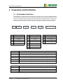
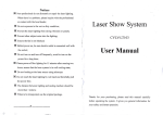
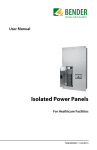
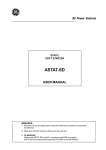
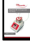
TM User Manual LifeGuard Ground Fault Circuit Interrupter (GFCI) NAE1085010 / 11.2012 Bender Inc. USA: 700 Fox Chase Coatesville, PA 19320 Toll Free: 800-356-4266 Phone: 610-383-9200 Fax: 610-383-7100 E-mail: [email protected] Canada: 5810 Ambler Drive, Unit 1 Mississauga, ON L4W 4J5 Toll Free: 800-243-2438 Phone: 905-602-9990 Fax: 905-602-9960 E-mail: [email protected] © Bender Inc. Web: http://www.bender.org All rights reserved. Content subject to change. Table of Contents 1. Introduction .................................................................................................. 5 1.1 LifeGuard Series Ground Fault Circuit Interrupter ....................................................... 5 1.2 Build Variations and Instructions ....................................................................................... 5 2. Safety Instructions ....................................................................................... 7 3. Preparation and Verification ....................................................................... 9 3.1 Part Number Verification ....................................................................................................... 9 4. Installation, Connection, and Adjustments ............................................. 10 4.1 Mounting ................................................................................................................................. 10 4.1.1 Mounting 4X Polycarbonate Enclosure (4X-P-CH Option)...................................... 10 4.1.2 Mounting 4X Stainless Steel Enclosure (4X-SS-CH Option) .................................... 11 4.1.3 Mounting Backplate-Only With No Enclosure (N Option)....................................... 12 4.2 Wiring ........................................................................................................................................ 13 4.2.1 Wiring Diagram - Single-Phase, Two-Wire Configurations (L1, N) ...................... 14 4.2.2 Wiring Diagram - Three-Phase, Three-Wire Configurations (L1, L2, L3) ............ 15 4.2.3 Wiring Diagram - Three-Phase, Four-Wire Configurations (L1, L2, L3, N) ......... 16 4.2.4 Wiring Diagram - 240Y/120 VAC Configurations (L1, L2, N) .................................. 17 4.2.5 Additional Wiring Instructions for Backplate-Only Models ................................... 18 4.3 Field Adjustments ................................................................................................................. 19 4.3.1 Field Adjustments, Option “6” .......................................................................................... 19 4.3.2 Field Adjustments, Option “6/20” ................................................................................... 19 4.3.3 Field Adjustments, Option “A” ......................................................................................... 20 4.3.4 Field Adjustments, Option “B” .......................................................................................... 21 4.3.5 Field Adjustments, Option “C” .......................................................................................... 22 4.3.6 Field Adjustments, Option “D” ......................................................................................... 23 5. Operation .................................................................................................... 24 LifeGuard 5.1 Front Panel Display ............................................................................................................... 24 5.2 Apply Power to the GFCI .................................................................................................... 25 5.3 Procedure for Performing a Functional Test ............................................................... 25 © 2012 Bender Inc. All Rights Reserved 3 Table of Contents 4 © 2012 Bender Inc. All Rights Reserved LifeGuard Introduction 1. Introduction 1. 1 LifeGuard Series Ground Fault Circuit Interrupter LifeGuard series Ground Fault Circuit Interrupters (GFCIs) are designed to detect and interrupt hazardous ground fault currents in grounded electrical systems. The GFCI is installed in-line between the power source and electrical loads. If a ground fault is detected, the integrated contactor will interrupt the power conductors of the circuit. The GFCI may then be manually reset once the ground fault has been cleared. The test and reset pushbuttons on the front of the enclosure also function as power and tripped LEDs, providing clear indication of the status of the GFCI. Standard LifeGuard GFCIs are packaged in a NEMA rated enclosure, with options including NEMA 4X polycarbonate and NEMA 4X stainless steel. LifeGuard GFCIs may also be ordered on the backplate only with no enclosure, to be integrated into an existing cabinet. This manual covers standard LifeGuard models up to 100 A rated load current. For higher rated builds, as well as builds with customized options, consult the manufacturer. 1. 2 Build Variations and Instructions LifeGuard GFCIs are built-to-order systems. Variations may exist based on the type of build and the system it is being used on. When installing and using the device, ensure that you are using the correct directions based on the device purchased and the system it is being used on. Refer to Section 3 of this manual for more information on variations between models. Possible variations include, but are not limited to: LifeGuard System voltage and load amperage rating Number of system conductors / poles Trip level setting (adjustable or fixed) Time delay (Fixed inverse time curve or adjustable) Enclosure type, or on backplate only © 2012 Bender Inc. All Rights Reserved 5 Introduction This page intentionally left blank. 6 © 2012 Bender Inc. All Rights Reserved LifeGuard Safety Instructions 2. Safety Instructions DANGER Hazard of Electric Shock, Burn, or Explosion Only qualified maintenance personnel shall operate or service this equipment. These instructions should not be viewed as sufficient for those who are not otherwise qualified to operate or service this equipment. This document is intended to provide accurate information only. No responsibility is assumed by BENDER for any consequences arising from use of this document. Turn OFF all sources of electrical power before performing any inspections, tests, or service on this equipment. Assume all circuits are live until they have been properly de-energized, tested, grounded, and tagged. Failure to observe these precautions will result in equipment damage, severe personal injury, or death. Proper operation of this equipment depends on proper installation. Neglecting fundamental installation techniques will result in equipment damage, severe personal injury, or death. Do not make any modifications to the equipment. Failure to observe this precaution will result in equipment damage or personal injury. Only use manufacturer’s and manufacturer recommended accessories with this equipment. Failure to do so may damage the equipment beyond repair. LifeGuard © 2012 Bender Inc. All Rights Reserved 7 Safety Instructions This page intentionally left blank. 8 © 2012 Bender Inc. All Rights Reserved LifeGuard Preparation and Verification 3. Preparation and Verification 3. 1 Part Number Verification LifeGuard GFCIs are customized to the system they are being used on. The part number ordered details important information such as system voltage / amperage, trip level rating, etc. Before installing the GFCI, verify that the received device is correct based on the system parameters. A sample part number is given below with available options. Instructions for installations as well as available adjustments will vary based on the model - refer to the appropriate section for more information. LG 100 - 1 - 480 3/3 - 6 / 20 3 2 - 5 4 3: Conductors / Phases 2: System Voltage (L-L) 1: Load Amperage 4X - P - CH 20 20 amperes 120 120 volts 1/2 L1, N (page 14) 40 40 amperes 208 208 volts 2/3 L1, L2, N (page 17) 60 60 amperes 240 240 volts 3/3 L1, L2, L3 (page 15) 80 80 amperes 277 277 volts 3/4 L1, L2, L3, N (page 16) 100 100 amperes 480 480 volts 575 575 volts 600 600 volts 4: Trip Level, Detection Capability, Time Delay 6 6/20 6 mA fixed, AC/DC, fixed inverse time curve (page 19) 6/20 mA switch, AC/DC, fixed inverse time curve (page 19) A 6 - 600 mA adjustable, AC only, 0 - 10 s adjustable (page 20) B 10 mA - 10 A adjustable, AC only, 0 - 10 s adjustable (page 21) C 10 - 500 mA adjustable, AC/DC, 0 - 10 s adjustable (page 22) D 30 mA - 3 A adjustable, AC/DC, 0 - 10 s adjustable (page 23) 5: Enclosure Type 4X-P-CH NEMA 4X polycarbonate enclosure (page 10) 4X-SS-CH NEMA 4X stainless steel enclosure (page 11) N LifeGuard No enclosure, built on backplate only (page 12 and page 18) © 2012 Bender Inc. All Rights Reserved 9 Installation, Connection, and Adjustments 4. Installation, Connection, and Adjustments 4. 1 Mounting 4.1.1 Mounting 4X Polycarbonate Enclosure (4X-P-CH Option) The standard enclosure for LifeGuard series GFCIs is a NEMA 4X polycarbonate enclosure. The enclosure includes mounting feet and separate instructions on wall-mounting the enclosure. Refer to these instructions for more information. Dimensions below are in inches (mm). 10 Enclosure AxB C D E F G 12x10x6 10.25" x 8.25" (260.5 x 209.5) 12.75" (324) 10.75" (273) 13.4" (340) 7.7" (195.5) 12.3" (312.5) © 2012 Bender Inc. All Rights Reserved LifeGuard Installation, Connection, and Adjustments 4.1.2 Mounting 4X Stainless Steel Enclosure (4X-SS-CH Option) LifeGuard GFCIs are also available in a NEMA 4X stainless steel enclosure. The enclosure includes mounting feet and separate instructions on wall-mounting the enclosure. Refer to these instructions for more information. Dimensions below are in inches (mm). LifeGuard Enclosure AxBxC DxE GxH J 16x12x6 16" x 12" x 6" (406 x 305 x 152) 14.2" x 10.2" (361 x 259) 14.5" x 10.5" (368 x 267) 8" (203) © 2012 Bender Inc. All Rights Reserved 11 Installation, Connection, and Adjustments 4.1.3 Mounting Backplate-Only With No Enclosure (N option) This section applies to LifeGuard models purchased without an enclosure with the assembly on the backplate only. Backplate-only models are typically integrated into existing cabinets or machinery. The GFCI must be mounted in a location suitable to protect live electrical equipment. Use four (4) #10 screws for mounting. The vertical clearance is 6 inches (152 mm). Along with the system conductor wiring instructions in section 4, additional wiring instructions for backplate-only models can be found on page 18. A C 12 B D Backplate AxB CxD 8.75" x 10.5" (222 x 267) 8.25" x 10.25" (210 x 260) © 2012 Bender Inc. All Rights Reserved LifeGuard Installation, Connection, and Adjustments 4. 2 Wiring LifeGuard GFCIs are installed in series with the main circuit, in between the source of power and the equipment load. Connection of the main circuit conductors varies based on quantity of conductors and system voltage. Backplate-only options require additional control circuit connections. DANGER Turn off all sources of electrical power before installing this equipment. Observe all local, state, and national codes, standards, and regulations when installing this equipment. Failure to observe this precaution will result in equipment damage, severe personal injury, or death. Locate the correct wiring diagram in the table below. In general, the following steps must be taken and observed: – All active conductors, including the neutral if is being used, must be brought through the current transformer, and landed on the line side of the contactor. All active conductors are then brought out from the load side of the contactor to the load / remaining branch of the circuit. – The ground conductor wire is landed on the ground lug on the backplate. The ground wire is NOT routed through the current transformer. Voltage Conductors (NOT including ground) Wiring diagram 120 VAC 1ph / 2w (L1, N) page 14 208 VAC 3ph / 3w (L1, L2, L3) page 15 208/120 VAC 3ph / 4w (L1, L2, L3, N) page 16 240/120 VAC 3ph / 3w (L1, L2, N) page 17 277 VAC 1ph / 2w (L1, N) page 14 480 VAC 3ph / 3w (L1, L2, L3) page 15 3ph / 4w (L1, L2, L3, N) page 16 3ph / 3w (L1, L2, L3) page 15 3ph / 4w (L1, L2, L3, N) page 16 480/277 VAC 600 VAC 600/346 VAC Additional wiring instructions for backplate-only models may be found on page 18. LifeGuard © 2012 Bender Inc. All Rights Reserved 13 Installation, Connection, and Adjustments 4.2.1 Wiring diagram - single-phase, two-wire configurations (L1, N) Connection Legend: Line Side 14 Load Side Phase L1 Contactor Line Side 1L1 Contactor Load Side 2T1 Load Phase L1 Neutral Contactor Line Side 3L2 Contactor Load Side 4T2 Neutral Ground Ground Lug Ground Ground at load © 2012 Bender Inc. All Rights Reserved LifeGuard Installation, Connection, and Adjustments 4.2.2 Wiring diagram - three-phase, three-wire configurations (L1, L2, L3) Connection Legend: Line Side LifeGuard Load Side Phase L1 Contactor Line Side 1L1 Contactor Load Side 2T1 Load Phase L1 Phase L2 Contactor Line Side 3L2 Contactor Load Side 4T2 Load Phase L2 Phase L3 Contactor Line Side 5L3 Contactor Load Side 6T3 Load Phase L3 Ground Ground Lug Ground Ground at load © 2012 Bender Inc. All Rights Reserved 15 Installation, Connection, and Adjustments 4.2.3 Wiring diagram - three-phase, four-wire configurations (L1, L2, L3, N) Connection Legend: Line Side 16 Load Side Phase L1 Contactor Line Side 1L1 Contactor Load Side 2T1 Load Phase L1 Phase L2 Contactor Line Side 3L2 Contactor Load Side 4T2 Load Phase L2 Phase L3 Contactor Line Side 5L3 Contactor Load Side 6T3 Load Phase L3 Neutral Contactor Line Side 7L4 Contactor Load Side 8T4 Neutral Ground Ground Lug Ground Ground at load © 2012 Bender Inc. All Rights Reserved LifeGuard Installation, Connection, and Adjustments 4.2.4 Wiring diagram - 240Y/120 VAC configurations (L1, L2, N) Connection Legend: Line Side LifeGuard Load Side Phase L1 Contactor Line Side 1L1 Contactor Load Side 2T1 Load Phase L1 Neutral Contactor Line Side 3L2 Contactor Load Side 4T2 Neutral Phase L2 Contactor Line Side 5L3 Contactor Load Side 6T3 Load Phase L2 Ground Ground Lug Ground Ground at load © 2012 Bender Inc. All Rights Reserved 17 Installation, Connection, and Adjustments 4.2.5 Additional wiring instructions for backplate-only models Models pre-built in an enclosure come pre-wired for all indication, test, and reset functions. Backplate-only models require additional wiring to complete these functions. Refer to the wiring diagram and legend below. Connection Legend: Contacts noted with an asterisk (*) below are provided with 120 VAC from the backplate. Contact 18 Description Off.1 / Off.2 N/C contact / pushbutton, STOP function. Opening this contact will not allow the GFCI to close and energize the load side. Test.1 / Test.2 N/O contact / pushbutton, TEST function. Closing this contact for at least 2 seconds initiates a self-test. On 1.1 / On 1.2 N/O contact / pushbutton, RESET function. Closing this contact provides reset functionality. On 2.1 / On 2.2 N/O contact / pushbutton, ON function. COM LED * Common for indicator lights. Cir Trip * TRIPPED light. Load On * ON light. © 2012 Bender Inc. All Rights Reserved LifeGuard Installation, Connection, and Adjustments 4. 3 Field Adjustments Adjustable options such as the trip level and time delay vary by model number. Part 4 of the part number as shown in Section 3.1 determines what options are available. Refer to the table below for the section on how to adjust any available options. 4.3.1 Option (See Section 3.1) Refer To "6" page 19 "6/20" page 19 "A" page 20 "B" page 21 "C" page 22 "D" page 23 Field adjustments, Option "6" Models with option "6" utilize the RCMA473L6-33 ground fault monitor. These models are fixed at a 6 mA trip level and use a fixed inverse time curve. Neither is field adjustable. This monitor can detect both AC and DC faults, and works on systems with variable frequency drives. 4.3.2 Field adjustments, Option "6/20" Models with option "6" utilize the RCMA473LY6/20-132 ground fault monitor. These models utilize a fixed inverse time curve which is not adjustable. A DIP switch on the front of the monitor allows the switching of the trip level between 6 mA and 20 mA. This monitor can detect both AC and DC faults, and works on systems with variable frequency drives. LifeGuard © 2012 Bender Inc. All Rights Reserved 19 Installation, Connection, and Adjustments 4.3.3 Field adjustments, Option "A" Models with option "A" utilize the RCM470LY-7113 or equivalent ground fault monitor. These models allow for adjustment of the trip level steplessly from 6 mA to 600 mA. An adjustable time delay is also available, from 0 to 10 seconds. This monitor detects only AC faults, and is not compatible with systems with variable frequency drives. All adjustments are made using the DIP switches and potentiometers on the face of the monitor. Open the enclosure to view the ground fault monitor and follow the instructions below to make any necessary adjustments. DO NOT CHANGE THE FIRST TWO DIP SWITCHES FROM THE LEFT. These are essential for proper operation of the GFCI. Alarm response range 6 - 60 mA 10 - 100 mA 20 - 200 mA 30 - 300 mA 40 - 400 mA 6 10 20 30 40 60 - 600 mA Time delay multiplier – Only one (or none) of the numbered DIP switches shall be active (down) at any time. This functions as the "starting point" for the desired trip level. Once active, use the potentiometer "x mA" to act as a multipler of this value, from x1 to x10. – For example, to use a trip level of 100 mA, press the "10" DIP switch down, and the remaining numbered DIP switches up. Turn the potentiometer "x mA" fully to 10. – Use the potentiometer "t/s" to adjust the trip level between 0 and 1 second. Use the last DIP switch on the right to multiply this value by 10 if desired. For example, for a time delay of 5 seconds, adjust the "t/s" potentiometer halfway to 0.5, and press the last DIP switch down to x10. 20 © 2012 Bender Inc. All Rights Reserved LifeGuard Installation, Connection, and Adjustments 4.3.4 Field adjustments, Option "B" Models with option "B" utilize the RCM470LY-13 or equivalent ground fault monitor. These models allow for adjustment of the trip level steplessly from 10 mA to 10 A. An adjustable time delay is also available, from 0 to 10 seconds. This monitor detects only AC faults, and is not compatible with systems with variable frequency drives. All adjustments are made using the DIP switches and potentiometers on the face of the monitor. Open the enclosure to view the ground fault monitor and follow the instructions below to make any necessary adjustments. DO NOT CHANGE THE FIRST TWO DIP SWITCHES FROM THE LEFT. These are essential for proper operation of the GFCI. Alarm response range 10 - 100 mA 30 - 300 mA 100 - 1000 mA 300 - 3000 mA 500 - 5000 mA 1 - 10 A Time delay multiplier – Only one (or none) of the numbered DIP switches shall be active (down) at any time. This functions as the "starting point" for the desired trip level. Once active, use the potentiometer "x mA" to act as a multipler of this value, from x1 to x10. – For example, to use a trip level of 50 mA, press the "10" DIP switch down, and the remaining numbered DIP switches up. Turn the potentiometer "x mA" halfway to 5. – Use the potentiometer "t/s" to adjust the trip level between 0 and 1 second. Use the last DIP switch on the right to multiply this value by 10 if desired. For example, for a time delay of 5 seconds, adjust the "t/s" potentiometer halfway to 0.5, and press the last DIP switch down to x10. LifeGuard © 2012 Bender Inc. All Rights Reserved 21 Installation, Connection, and Adjustments 4.3.5 Field adjustments, Option "C" Models with option "C" utilize the RCMA420-D-2 or equivalent ground fault monitor. These models allow for adjustment of the trip level steplessly from 10 mA to 500 mA. An adjustable time delay is also available, from 0 to 10 seconds. A digital display shows the measured fault current in real-time. This monitor detects both AC and DC faults, and works with systems with variable frequency drives. All adjustments are made using the three blue pushbuttons and the digital display. Open the enclosure to view the ground fault monitor and follow the instructions below to make any necessary adjustments. Three blue pushbuttons are present from left to right on the device - UP arrow, DOWN arrow, and MENU / ENTER button. These are used to modify settings. DO NOT CHANGE ANY OTHER SETTINGS OTHER THAN THOSE LISTED BELOW. All other settings are essential for proper operation of the GFCI and shall not be modified. Adjust trip level – Hold the MENU button down for several seconds. A flashing "AL" will appear on the screen. – Press the MENU button. a mA value will appear in the middle of the screen, with "I 2" at the top right hand corner. – Press the MENU button. The number in the middle will flash. > 1.5 sec < 1.5 sec < 1.5 sec > 1.5 sec – Press the UP and DOWN arrows to reach the desired trip value. Press the MENU button to confirm. – Hold down the MENU button for several seconds. Flashing "AL" will appear again. Repeat this step to exit the menu and return to the main screen. < 1.5 sec T > 1.5 sec R Set-Point Adjustment = Flashing Symbol Adjust time delay – Hold the MENU button down for several seconds. A flashing "AL" will appear on the screen. – Press the DOWN button until a flashing "t" is reached. Press the MENU button. – Press the DOWN button once. A number will appear in the middle, "t on" in the bottom left hand corner, and a "2" at the top right hand corner. – Press the MENU button. The number in the middle will flash. Press the UP and DOWN buttons to reach the desired time delay. Press MENU to confirm. – Hold down the MENU button for several seconds. Flashing "t" will appear again. Repeat this step to exit the menu and return to the main screen. T R ton2 Adjustment 0...10 seconds > 1.5 sec < 1.5 sec R Press Twice > 1.5 sec < 1.5 sec > 1.5 sec R = Flashing Symbol 22 © 2012 Bender Inc. All Rights Reserved LifeGuard Installation, Connection, and Adjustments 4.3.6 Field adjustments, Option "D" Models with option "C" utilize the RCMA423-D-2 or equivalent ground fault monitor. These models allow for adjustment of the trip level steplessly from 30 mA to 3 A. An adjustable time delay is also available, from 0 to 10 seconds. A digital display shows the measured fault current in real-time. This monitor detects both AC and DC faults, and works with systems with variable frequency drives. All adjustments are made using the three blue pushbuttons and the digital display. Open the enclosure to view the ground fault monitor and follow the instructions below to make any necessary adjustments. Three blue pushbuttons are present from left to right on the device - UP arrow, DOWN arrow, and MENU / ENTER button. These are used to modify settings. DO NOT CHANGE ANY OTHER SETTINGS OTHER THAN THOSE LISTED BELOW. All other settings are essential for proper operation of the GFCI and shall not be modified. Adjust trip level – Hold the MENU button down for several seconds. A flashing "AL" will appear on the screen. – Press the MENU button. a mA value will appear in the middle of the screen, with "I 2" at the top right hand corner. – Press the MENU button. The number in the middle will flash. > 1.5 sec < 1.5 sec < 1.5 sec > 1.5 sec – Press the UP and DOWN arrows to reach the desired trip value. Press the MENU button to confirm. – Hold down the MENU button for several seconds. Flashing "AL" will appear again. Repeat this step to exit the menu and return to the main screen. < 1.5 sec T > 1.5 sec R Set-Point Adjustment = Flashing Symbol Adjust time delay – Hold the MENU button down for several seconds. A flashing "AL" will appear on the screen. – Press the DOWN button until a flashing "t" is reached. Press the MENU button. – Press the DOWN button once. A number will appear in the middle, "t on" in the bottom left hand corner, and a "2" at the top right hand corner. – Press the MENU button. The number in the middle will flash. Press the UP and DOWN buttons to reach the desired time delay. Press MENU to confirm. – Hold down the MENU button for several seconds. Flashing "t" will appear again. Repeat this step to exit the menu and return to the main screen. T R ton2 Adjustment 0...10 seconds > 1.5 sec < 1.5 sec R Press Twice > 1.5 sec < 1.5 sec > 1.5 sec R = Flashing Symbol LifeGuard © 2012 Bender Inc. All Rights Reserved 23 Operation 5. Operation 5. 1 Front Panel Display POWER ON CIRCUIT TRIPPED Push to Reset Push to Test 2 1 OPERATION GFCI Ground Fault Circuit Interrupter The GREEN “POWER ON” lamp illuminates when power is available on the load side. The RED “CIRCUIT TRIPPED” lamp illuminates when power is removed from the circuit. If the GFCI trips,clear the fault and press the “Reset” button to resume operation. TESTING Press the “Test” button for > 2 seconds. Unit must trip. Press the “Reset” button for > 1 second. Unit must reset. Life Guard GFCI 24 Technical Support Bender Inc. Tel. (800) 356-4266 E-mail: [email protected] 1 POWER Light / RESET button: Illuminates green when the GFCI has received power and has not tripped. A momuntary push resets the GFCI if it has tripped and the fault has been cleared. 2 TRIPPED Light / TEST button: Illuminates red when the GFCI has tripped. Pushing this button for at least 2 seconds initiates a functional test of the GFCI. © 2012 Bender Inc. All Rights Reserved LifeGuard Operation 5. 2 Apply Power to the GFCI To apply power, close the circuit breaker / disconnect on the line side of the GFCI. The GFCI will immediately power on. If there are no ground faults present on the load side, the green Power ON light will illuminate and the load side will be energized. 5. 3 Procedure for Performing a Functional Test Performing a functional test of the LifeGuard GFCI will disengage the contactor inside and will interrupt power to any loads on the load side of the contactor. Follow the steps below to perform a functional test: Press and hold the TEST button for at least 2 seconds. The GFCI must trip and the red "Circuit Tripped" light will illuminate. The green "Power ON" light will no longer illuminate. The contactor will open and no power will be present on the load side. Momuntarily press the RESET button. The GFCI must reset. The red "Circuit Tripped" light will go out and the green "Power ON" light will illuminate. The contactor will pull in and power will be restored to the load side. BENDER recommends pressing the TEST button monthly to ensure proper operation of the GFCI. LifeGuard © 2012 Bender Inc. All Rights Reserved 25 Operation 26 © 2012 Bender Inc. All Rights Reserved LifeGuard Local Service Representative Name: _______________________________________________________ Company: ____________________________________________________ Address: _____________________________________________________ City: ____________________ Phone: __________________ _ State: _______ Zip: ___________ Fax: __________________________ Note: These instructions must be framed and placed in a location recommended by the local inspection authority for quick reference. Bender Inc. USA: 700 Fox Chase Coatesville, PA 19320 Toll Free: 800-356-4266 Phone: 610-383-9200 Fax: 610-383-7100 E-mail: [email protected] Canada: 5810 Ambler Drive, Unit 1 Mississauga, ON L4W 4J5 Toll Free: 800-243-2438 Phone: 905-602-9990 Fax: 905-602-9960 E-mail: [email protected] Web: http://www.bender.org