1
Installation, Connection, and Adjustments
4. 2 Wiring
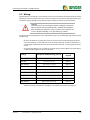
LifeGuard GFCIs are installed in series with the main circuit, in between the source of power and the
equipment load. Connection of the main circuit conductors varies based on quantity of conductors
and system voltage. Backplate-only options require additional control circuit connections.
DANGER
Turn off all sources of electrical power before installing this equipment.
Observe all local, state, and national codes, standards, and regulations
when installing this equipment. Failure to observe this precaution will
result in equipment damage, severe personal injury, or death.
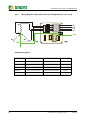
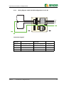
Locate the correct wiring diagram in the table below. In general, the following steps must be taken
and observed:
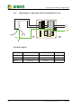
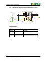
– All active conductors, including the neutral if is being used, must be brought through the
current transformer, and landed on the line side of the contactor. All active conductors are
then brought out from the load side of the contactor to the load / remaining branch of the
circuit.
– The ground conductor wire is landed on the ground lug on the backplate. The ground wire
is NOT routed through the current transformer.
Voltage
Conductors (NOT including ground)
Wiring
diagram
120 VAC
1ph / 2w (L1, N)
page 14
208 VAC
3ph / 3w (L1, L2, L3)
page 15
208/120 VAC
3ph / 4w (L1, L2, L3, N)
page 16
240/120 VAC
3ph / 3w (L1, L2, N)
page 17
277 VAC
1ph / 2w (L1, N)
page 14
480 VAC
3ph / 3w (L1, L2, L3)
page 15
3ph / 4w (L1, L2, L3, N)
page 16
3ph / 3w (L1, L2, L3)
page 15
3ph / 4w (L1, L2, L3, N)
page 16
480/277 VAC
600 VAC
600/346 VAC
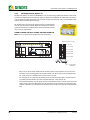
Additional wiring instructions for backplate-only models may be found on page 18.
LifeGuard
© 2012 Bender Inc. All Rights Reserved
13