1
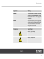
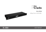
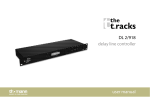
DL 2/918
delay line controller
user manual
Musikhaus Thomann e.K.
Treppendorf 30
96138 Burgebrach
Germany
Telephone: +49 (0)9546 9223-0
email: [email protected]
Internet: www.thomann.de
17.11.2011
Table of contents
Table of contents
1
General notes............................................................................................................................................... 4
2
Safety instructions..................................................................................................................................... 6
3
Installation and operation.................................................................................................................. 10
4
Connectors and controls...................................................................................................................... 12
5
Operation.................................................................................................................................................... 17
6
Technical specifications....................................................................................................................... 20
7
Protecting the environment.............................................................................................................. 22
DL 2/918
3
General notes
1
General notes
This user manual contains important information on the safe operation of the device. Read and
follow all safety notes and all instructions. Save this manual for future reference. Make sure
that it is available to all persons using this device. If you sell the device to another user, be sure
that they also receive this manual.
Our products are subject to a process of continuous development. We therefore reserve the
right to make changes without notice.
Symbols and signal words
This section gives an overview of the symbols and signal words used in this user manual.
delay line controller
4
General notes
Signal word
Meaning
DANGER!
This combination of symbol and signal word
indicates an immediate dangerous situation
that will result in death or serious injury if it is
not avoided.
NOTICE!
This combination of symbol and signal word
indicates a possible dangerous situation that
can result in material and environmental
damage if it is not avoided.
Warning signs
Type of danger
Warning – high-voltage.
Warning – danger zone.
DL 2/918
5
Safety instructions
2
Safety instructions
Intended use
Use the device only as described in this user manual. Any other use or use under other oper‐
ating conditions is considered to be improper and may result in personal injury or property
damage. No liability will be assumed for damages resulting from improper use.
This device may be used only by persons with sufficient physical, sensorial, and intellectual
abilities and having corresponding knowledge and experience. Other persons may use this
device only if they are supervised or instructed by a person who is responsible for their safety.
Safety
DANGER!
Danger for children
Ensure that plastic bags, packaging, etc. are disposed of properly and are not
within reach of babies and young children. Choking hazard!
Ensure that children do not detach any small parts (e.g. knobs or the like) from
the unit. They could swallow the pieces and choke!
Never let children unattended use electrical devices.
delay line controller
6
Safety instructions
DANGER!
Electric shock caused by high voltages inside
Within the device there are areas where high voltages may be present. Never
remove any covers.
There are no user-serviceable parts inside.
DANGER!
Electric shock caused by short-circuit
Always use proper ready-made insulated mains cabling (power cord) with a pro‐
tective contact plug. Do not modify the mains cable or the plug. Failure to do so
could result in electric shock/death or fire. If in doubt, seek advice from a regis‐
tered electrician.
DL 2/918
7
Safety instructions
NOTICE!
Risk of fire
Do not block areas of ventilation. Do not install the device near any direct heat
source. Keep the device away from naked flames.
NOTICE!
Operating conditions
This device has been designed for indoor use only. To prevent damage, never
expose the device to any liquid or moisture. Avoid direct sunlight, heavy dirt, and
strong vibrations.
delay line controller
8
Safety instructions
NOTICE!
Power supply
Before connecting the device, ensure that the input voltage (AC outlet) matches
the voltage rating of the device and that the AC outlet is protected by a residual
current circuit breaker. Failure to do so could result in damage to the device and
possibly injure the user.
Unplug the device before electrical storms occur and when it is unused for long
periods of time to reduce the risk of electric shock or fire.
DL 2/918
9
Installation and operation
3
Installation and operation
Unpack and check carefully there is no transportation damage before using the unit.
Establish all connections as long as the unit is switched off. Use the shortest possible highquality cables for all connections.
XLR connectors for signal inputs
and outputs
Balanced female XLR panel connectors are used for the signal inputs. Male XLR panel connec‐
tors are used for the signal outputs The figure and the table show the XLR pin assignment.
1
Ground
2
Signal (+)
3
Signal (–)
delay line controller
10
Installation and operation
Jack plug for signal inputs and
outputs
Rack mounting
The figure and the table show the pin assignment of the ¼-inch (6.35-mm) monaural jack plug.
1
Signal
2
Ground
The unit has been designed for rack mounting in a standard 19-inch rack; it occupies one rack
unit.
DL 2/918
11
Connectors and controls
4
Connectors and controls
Front panel
delay line controller
12
Connectors and controls
1 INPUTS
Level meter LEDs for left and right channels.
The top-most "CLIP" LEDs light up when the unit's input level is too high. In this case, decrease the input level at the signal
source or use the corresponding "INPUT LEVEL" controls (13, 16) on the rear panel.
2 Display
Shows menu options and values set.
3 EDIT
Jog wheel for convenient value setting.
4 MENU
Calls up the menu for setting up delay options (units, steps).
5 DELAY
Enables setting up the delay with the jog wheel.
DL 2/918
13
Connectors and controls
6 BYPASS
Enables or disables the delay function.
7 CH-SEL
Calls up the menu for channel selection.
8 NOISE GATE
Calls up the menu for setting the noise gate threshold.
9 LOCK
Locks the current settings and protects against unintentional changes.
10 POWER
Power on/off switch. Switches the unit on and off.
delay line controller
14
Connectors and controls
Rear panel
11 Plug for mains cable with fuse holder
12 OUTPUTS2
Male XLR panel connector as signal output for channel 2 for direct connection with a mixer, power amplifier, or a recording
device.
13 INPUT LEVEL
Control for adjusting the input sensitivity for channel 2 in the range from –20 dB to +40 dB
DL 2/918
15
Connectors and controls
14 INPUTS2
Female XLR panel connector as signal input for channel 2
15 OUTPUTS1
Male XLR panel connector as signal output for channel 1 for direct connection with a mixer, power amplifier, or a recording
device.
16 INPUT LEVEL
Control for adjusting the input sensitivity for channel 1 in the range from –20 dB to +40 dB
17 INPUTS1
Female XLR panel connector as signal input for channel 1
18 ¼-inch (6.35-mm) jack as signal input for channel 1
19 ¼-inch (6.35-mm) jack as signal output for channel 1 for direct connection with a mixer, power amplifier, or a recording device.
20 ¼-inch (6.35-mm) jack as signal input for channel 2
21 ¼-inch (6.35-mm) jack as signal output for channel 2 for direct connection with a mixer, power amplifier, or a recording device.
22 Serial interface, no function
delay line controller
16
Operation
5
Operation
Power on
When all connections have been established, turn on the device using the main switch (10).
The display shows the last set delay value and the last used unit. You can adjust the delay time
by turning the jog wheel.
The delay time can be set separately for either channel in the range from 0 to 2730 ms (corre‐
sponding to 936.4 metres or 3074 feet).
Select options
The delay can be set as delay time (in milliseconds) or as the corresponding distance (in metres
or feet). Based on the speed of sound, a delay time of 1000 ms corresponds to a distance of
343 metres (1126 feet). The delay time can be set in steps of 1 ms or 100 ms.
To select the delay options, press the [MENU] button. Using the jog wheel, select the ‘Delay
Tune’ option to select the step width or the ‘Del Count Sel’ option to set the unit. Then press
the [MENU] button. The corresponding submenu opens.
Select between either ‘100ms’ and ‘1ms’ or ‘ms’ , ‘metres’ , and ‘feet’ . Confirm your selection
with the [DELAY] button.
DL 2/918
17
Operation
Bypass delay
If you temporarily want to switch off the set delay without having to change the value, press
the [BYPASS] button. The text ‘DELAY OFF’ appears in the top line of the display.
To switch on the delay again, press the [BYPASS] button again. The text ‘DELAY ON’ appears in
the top line of the display.
Select channel
The set delay may affect either both channels or only one of them. To change the setting, press
the [CH-SEL] button twice. Using the jog wheel, you can select between ‘Left’ , ‘Right’ , and
‘L&R’ . Confirm your selection with the [DELAY] button.
Set noise gate threshold
The noise gate threshold specifies the level below which the output signal is muted. To change
the setting, press the [NOISE GATE] button.
delay line controller
18
Operation
Using the jog wheel, you can select a value between –66 dB and –24 dB. Confirm your selec‐
tion with the [DELAY] button.
Lock settings
To prevent unintentional changes of your values set, you can lock the settings of the unit. To
this end, press the [LOCK] button. The text ‘LOCK ON’ appears in the top line of the display.
To unlock, press the [LOCK] button again. The display shows the normal state again.
DL 2/918
19
Technical specifications
6
Technical specifications
Input
Female XLR panel connector, ¼-inch (6.35-mm) jack (balanced)
Input impedance
40 kΩ (balanced)
20 kΩ (unbalanced)
Input level
–20 dB…+4 dB
Output
Male XLR panel connector, (balanced) ¼-inch (6.35-mm) jack
Output impedance
66 Ω (balanced)
33 Ω (unbalanced)
Power consumption
10 W
Frequency response, ±1 dB
20 Hz…20 kHz
Dynamic range
> 110 dB, 20 Hz … 20 kHz
Signal-to-noise ratio
> 95 dB, 20 Hz … 20 kHz
Distortion
< 0.01 %, 1 kHz, 0 dB
delay line controller
20
Technical specifications
AD/DA converter
24-bit Sigma-Delta
Sampling rate
48 kHz
Input voltage
90 – 230 VAC, 50 Hz
Fuse
1 A / 250 V, slow, 5 mm × 20 mm
Dimensions (W × H × D)
482 mm × 45 mm × 152 mm (18.98 in. × 1.77 in. × 5.98 in.) (1 rack unit)
Weight
3 kg (6.61 lbs)
DL 2/918
21
Protecting the environment
7
Protecting the environment
Disposal of the packaging mate‐
rial
For the transport and protective packaging, environmentally friendly materials have been
chosen that can be supplied to normal recycling.
Ensure that plastic bags, packaging, etc. are properly disposed of.
Do not just dispose these materials with your normal household waste, but make sure that
they are fed to a recovery. Please follow the notes and markings on the packaging.
Disposal of your old device
This device is subject to the European directive 2002/96/EC.
Do not dispose the device with your normal household waste.
Dispose this device through an approved waste disposal firm or through your local waste
facility. When discarding the device, comply with the rules and regulations that apply in your
country. If in doubt, consult your local waste disposal facility.
delay line controller
22
Musikhaus Thomann e.K. · Treppendorf 30 · 96138 Burgebrach · Germany · www.thomann.de