1
AC Servo Actuator
SHA
series
manual
ISO14001
(Hotaka plant)
ISO9001
Introduction
Introduction
Thank you for purchasing our SHA series AC Servo Actuator.
• Improper handling or use of this product may result in an accident or reduced
life of the product. Read this document carefully and use the product correctly
so that the product can be used safely for many years to come.
• Product specifications are subject to change without notice.
• Keep this manual in a convenient location and refer to it as necessary when
operating or maintaining the actuator.
• The end user of the actuator should have a copy of this manual.
SAFETY GUIDE
SAFETY GUIDE
To use this actuator safely and correctly, be sure to read SAFETY GUIDE and other parts of this
manual carefully. It is important to fully understand the information provided herein before using the
actuator.
NOTATION
Important safety information you must note is provided herein. Be sure to observe these instructions.
Indicates a potentially hazardous situation, which, if not avoided, could result
in death or serious personal injury.
WARNING
Indicates a potentially hazardous situation, which, if not avoided, may result in
minor or moderate personal injury and/or damage to the equipment.
CAUTION
Indicates what should be performed or avoided to prevent non-operation or
malfunction of the product or negative effects on its performance or function.
LIMITATION OF APPLICATIONS
The equipment listed in this document may not be used for the applications listed below:
・Space equipment
・Automobile, automotive parts
・Aircraft, aeronautic equipment
・Amusement equipment, sport equipment, game machines
・Nuclear equipment
・Machine or devices acting directly on the human body
・Household apparatus
・Instruments or devices to transport or carry people
・Vacuum equipment
・Apparatus or devices used in special environments
If the above list includes your intending application for our products, please consult us.
CAUTION
Safety measures are essential to prevent accidents resulting
in death, injury or damage of the equipment due to
malfunction or faulty operation.
1
SAFETY GUIDE
SAFETY NOTE
ITEMS YOU SHOULD NOTE WHEN USING THE ACTUATOR
• PRECAUTIONS FOR ACTUATORS AT THE APPLICATION DESIGN PHASE
Always use under followings conditions.
CAUTION
The actuator is designed to be used indoors. Observe the following conditions:
・ Ambient temperature: 0℃ to 40℃
・ Ambient humidity: 20% to 80%RH (Non-condensation)
2
・ Vibration: Max 25 m/s
・ No contamination by water, oil
・ No corrosive or explosive gas
Follow the exact instructions in the related manuals to install
the actuator in the equipment.
・ Ensure precise alignment of the actuator shaft center and the
corresponding center in the application.
・ Failure to observe this caution may lead to vibration, resulting in damage of
output elements.
•
PRECAUTIONS FOR ACTUATORS IN OPERATION
Comply with the towque limits for the actuator.
・ Be aware, that if by accident, the arm attached to the output element hits a
solid object, the output element may become uncontrollable.
WARNING
Never connect cables directly to a power supply socket.
・ Each actuator must be operated with a proper driver.
・ Failure to observe this caution may lead to injury, fire or damage of the
actuator.
Do not apply impacts and shocks
・ The actuator directly connects with the encoder so do not use a hammer
during installation.
・ Failure to observe this caution could damage the encoder and may cause
uncontrollable operation.
Avoid handling of actuators by cables.
・ Failure to observe this caution may damage the wiring, causing
uncontrollable or faulty operation.
2
SAFETY GUIDE
ITEMS YOU SHOULD NOTE WHEN USING THE DRIVER
CAUTIONS RELATED TO THE DESIGN
Always use drivers under followings conditions.
CAUTION
The driver generates heat. Use under the following conditions while paying
careful attention to the heat radiation.
・ Mount in a vertical position keeping sufficient clearance.
・ 0℃ to 50℃, 95%RH or below (No condensation)
・ No vibration or physical shock
・ No dust, dirt, corrosive or inflammable gas
Use sufficient noise suppressing means and safe grounding.
Any noise generated on a signal wire will cause vibration or improper motion.
Conform to the following conditions.
・ Keep signal and power leads separated.
・ Keep leads as short as possible.
・ Ground actuator and driver at one single point, minimum ground resistance
class: D (less than 100 ohms)
・ Do not use a power line filter in the motor circuit.
Pay attention to negative torque by inverse load.
・ Inverse load may cause damages of drivers.
・ Please consult our sales office, if you intent to apply products for inverse
load.
Use a fast-response type ground-fault detector designed for
PWM inverters.
Do not use a time-delay-type ground-fault detector.
Safety measures are essential to prevent accidents resulting
in death, injury or damage of the equipment due to
malfunction or faulty operation.
CAUTIONS FOR USAGE
Never change wiring while power is active.
Make sure of power non-active before servicing the products. Failure to
observe this caution may result in electric shock or personal injury.
WARNING
Do not touch terminals or inspect products at least 5
minutes after turning OFF power.
・ Otherwise residual electric charges may result in electric shock.
・ Make installation of products not easy to touch their inner electric
components.
3
SAFETY GUIDE
Do not make a voltage resistance test.
CAUTION
・ Failure to observe this caution may result in damage of the control unit.
・ Please consult our sales office, if you intent to use a voltage resistance
test.
Do not operate control units by means of power ON/OFF
switching.
・ Start/stop operation should be performed via input signals.
・ Failure to observe this caution may result in deterioration of electronic
parts.
DISPOSAL
All products or parts have to be disposed of as industrial
waste.
CAUTION
4
Since the case or the box of drivers have a material indication, classify parts
and dispose them separately.
Contents
SAFETY GUIDE ...................................................................................................... 1
NOTATION ............................................................................................................. 1
LIMITATION OF APPLICATIONS............................................................................ 1
SAFETY NOTE ...................................................................................................... 2
Contents .................................................................................................................. 5
Chapter 1
Outlines
1-1 Overview ...................................................................................................... 1-1
1-2 Model ........................................................................................................... 1-2
1-3 Drivers and extension cables ....................................................................... 1-3
1-4 Specifications ............................................................................................... 1-4
1-5 Brake ......................................................................................................... 1-16
1-6 External dimensions................................................................................... 1-19
1-7 Mechanical accuracy ................................................................................. 1-31
1-8 One way positional accuracy ..................................................................... 1-33
1-9 Detector specifications (Absolute encoder)................................................ 1-35
1-10 Rigidity ....................................................................................................... 1-37
Moment stiffness ............................................................................................... 1-37
Torsional stiffness (HarmonicDrive® speed reducer with ratio greater than 51) .. 1-38
Torsional stiffness (Hollow planetary HPF series with reduction ratio 11) ........... 1-40
1-11 Direction of rotation .................................................................................... 1-41
1-12 Shock resistance........................................................................................ 1-42
1-13 Vibration resistance ................................................................................... 1-43
1-14 Operable range .......................................................................................... 1-44
1-15 Cable specifications ................................................................................... 1-59
Motor cable specifications ................................................................................. 1-59
Encoder cable specifications ............................................................................. 1-60
5
Contents
Chapter 2
Selection guidelines
2-1 SHA series selection .................................................................................... 2-1
Allowable load moment of inertia ......................................................................... 2-1
2-2 Change in load moment of inertia ................................................................ 2-6
2-3 Verifying and examining load weights .......................................................... 2-7
Maximum load moment load................................................................................ 2-8
Verifying life ......................................................................................................... 2-8
Verifying static safety coefficients ...................................................................... 2-10
2-4 Examining the operating conditions ........................................................... 2-11
Calculate the actuator rotation speed ................................................................ 2-11
Calculating and examining load moment of inertia ............................................. 2-11
Load torque calculation ..................................................................................... 2-12
Acceleration time and deceleration time ............................................................ 2-13
Examining effective torque and average rotation speed..................................... 2-14
Chapter 3
Installing the SHA actuator
3-1 Receiving Inspection .................................................................................... 3-1
Inspection procedure ........................................................................................... 3-1
3-2 Notices on handling ..................................................................................... 3-2
Installation and transmission torque .................................................................... 3-2
Precautions on installation ................................................................................... 3-4
Use of positioning pins ........................................................................................ 3-5
Surface treatments .............................................................................................. 3-5
3-3 Location and installation .............................................................................. 3-6
Environment of location ....................................................................................... 3-7
Installation ........................................................................................................... 3-7
Chapter 4
Options
4-1 Options ........................................................................................................... 4-1
With near origin and end limit sensors (option code: L) ....................................... 4-1
Cable taken out from side face (option code: Y) .................................................. 4-1
Extension cables ................................................................................................. 4-2
Chapter 5
Appendix
5-1 Unit conversion ............................................................................................ 5-1
5-2 Calculating inertia moment .......................................................................... 5-3
Formula of mass and inertia moment .................................................................. 5-3
Inertia moment of cylinder ................................................................................... 5-5
6
Contents
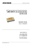
1 Overview of the SHA series
Radiation plate:
放熱板:
3 5 0 * 3350*350*18
50*18
150
Torque
[Nm]
トルク [Nm]
125
Motion range during
acceleration
and
加減速運転領域
deceleration
100
75
50
50%
duty range
5 0 % デューティ領域
Allowable continuous torque
Continuous
連続使用領域
motion
range
25
A
0
0
20
40
60
80
100
120
Rotation
speed min
[r/min]
回転速度 [r/
]
7
Contents
The nameplate values of various models are shown below.
SG/HP type
Model
Item
(1) Output at point A
(2) Voltage at point A
(3) Allowable
continuous
current
(4) Speed at point A
(5) Frequency at
point A
(6) Allowable range
temperature
(7) Number of phase
W
V
81
109
117
A
2.1
2.0
2.0
1.9
1.6
rpm
44
30
24
21
17
Hz
187
203
202
212
228
℃
40
-
3
Model
W
V
A
4.7
4.7
4.7
4.5
rpm
45
31
25
Hz
191
209
210
8
11
133
101
51
175
115
81
203
122
101
207
125
121
178
125
161
127
120
3.7
3.0
3.0
3.0
2.9
2.6
2.1
21
15
141
41
29
24.5
21
15
212
201
129
174
196
206
212
201
SHA40A
101 121
570 560
115 116
161
480
122
40
-
3
W
V
11
240
97
51
328
110
SHA32A
81
101
369 373
114 118
121
308
116
161
233
115
51
487
109
81
564
115
A
6.0
6.0
6.0
5.7
5.0
4.1
9.0
9.0
9.0
8.8
7.2
rpm
115
34
23
20
16.5
12.5
29
20.5
16.5
14
12
Hz
105
145
155
168
166
168
123
138
139
141
161
℃
40
-
3
Model
Item
(1) Output at point A
(2) Voltage at point A
(3) Allowable
continuous
current
(4) Speed at point A
(5) Frequency at
point A
(6) Allowable range
temperature
(7) Number of phase
SHA25A (Motor input voltage 200V)
℃
Model
Item
(1) Output at point A
(2) Voltage at point A
(3) Allowable
continuous
current
(4) Speed at point A
(5) Frequency at
point A
(6) Allowable range
temperature
(7) Number of phase
161
86
122
SHA25A
(Motor input voltage 100V)
51
81
101 121 161
165 188 190 178 127
61
64
65
64
62
Item
(1) Output at point A
(2) Voltage at point A
(3) Allowable
continuous
current
(4) Speed at point A
(5) Frequency at
point A
(6) Allowable range
temperature
(7) Number of phase
SHA20A
101 121
109 106
117 119
51
99
113
W
V
81
897
99
SHA58A
101 121
948 863
101 101
161
731
107
81
964
92
SHA65A
101 121
963 958
92
96
161
802
100
A
17.7
17.8
16.4
13.4
22.0
21.9
20.1
16.3
rpm
12
10
8.5
7.2
10
8
7.4
6.2
Hz
130
135
137
155
108
108
119
133
℃
40
-
3
Contents
CG type
Model
Item
(1) Output at point A
(2) Voltage at point A
(3) Allowable
continuous
current
(4) Speed at point A
(5) Frequency at
point A
(6) Allowable range
temperature
(7) Number of phase
W
V
80
108
116
A
2.1
2.1
2.1
2.0
1.7
rpm
44
29.5
24
21
17
Hz
183
197
200
210
227
℃
40
-
3
Model
W
V
SHA25A((Motor input
voltage 200V)
50
80
100 120 160
177 201 204 174 127
115 121 123 123 119
A
4.7
4.7
4.7
4.5
3.7
3.0
3.0
3.0
2.6
2.1
rpm
47
32
25.5
20.5
15
42
29
24
20.5
15
Hz
196
213
213
205
200
175
193
200
205
200
160
233
115
50
493
109
80
558
114
SHA40A
100 120
568 568
115 116
160
488
123
℃
40
-
3
Model
Item
(1) Output at point A
(2) Voltage at point A
(3) Allowable
continuous
current
(4) Speed at point A
(5) Frequency at
point A
(6) Allowable range
temperature
(7) Number of phase
160
85
122
SHA25A(Motor input voltage
100V)
50
80
100 120 160
167 191 192 174 127
62
65
65
63
61
Item
(1) Output at point A
(2) Voltage at point A
(3) Allowable
continuous
current
(4) Speed at point A
(5) Frequency at
point A
(6) Allowable range
temperature
(7) Number of phase
SHA20A
100
120
108
106
116
119
50
97
112
SHA32A
100 120
373 308
117 116
W
V
50
321
109
80
372
114
A
6.0
6.0
5.7
5.0
4.1
9.0
9.0
9.0
8.8
7.2
rpm
34
23.5
20
16.5
12.5
30
20.5
16.6 14.2
12.2
Hz
142
157
167
165
167
125
137
138
163
℃
40
-
3
142
9
Contents
10
Chapter 1
Overview
This chapter explains the features, functions and specifications of the actuator.
1-1 Overview ············································································ 1-1
1-2 Model ················································································ 1-2
1-3 Combinations with drivers and extension cables ························· 1-3
1-4 Specifications ······································································ 1-4
1-5 Motor shaft holding brake ···················································· 1-16
1-6 External dimensions ··························································· 1-19
1-7 Mechanical accuracy ·························································· 1-31
1-8 One Way positional accuracy················································ 1-33
1-9 Detector specifications (Absolute encoder) ······························ 1-35
1-10 Rigidity ·········································································· 1-37
1-11 Rotation direction ···························································· 1-41
1-12 Shock resistance ····························································· 1-42
1-13 Resistance to vibration······················································ 1-43
1-14 Operable range ······························································· 1-44
1-15 Cable specifications ························································· 1-59
1-1 Overview
1
Outlines
2
3
1-1 Overview
The SHA series of AC Servo Actuators provide high torque and high accuracy rotary motion. These AC Servo
Actuators are each composed of a Harmonic Drive® speed reducer for precise control and a flat, high
performance AC servo motor with an integral absolute multi-turn encoder. The SHA series AC Servo Actuators all
feature a large hollow shaft through the axis of rotation.
There are 3 types of speed reducers: SG with SHG series incorporated, HP with HPF series incorporated, and
CG with the newly added CSG series incorporated. They are an advanced version of current FHA series AC
Servo Actuators having a flat, hollow structure.
4
One key feature of the SHA actuators is their compact size. The outside diameter has been minimized, providing
a maximum torque/volume ratio which is approximately double that of conventional FHA actuators. A through
hole is provided in the center of the actuator, through which wiring, air lines, laser beams or concentric shafts may
be passed.
5
The HA-800 series driver is a dedicated family of servo drive units for position/speed control, developed
exclusively for driving SHA series actuators. The small, multi-functional drivers control the SHA series actuators'
operations with great accuracy and precision. Additionally, the REL driver series may be used, which provides
interface to many network field buses.
6
7
8
◆
High-torque SHG series Harmonic Drive® speed reducers are incorporated into the actuator for precise control
and the outer diameter of the actuator has been reduced by 20% compared to our FHA series. As a result, the
maximum torque/volume ratio has approximately doubled compared to our previous actuator designs. Based on
maximum torque, you can select a model which is one size smaller. Also, the output torque is approximately 10
times higher than direct drive motors of similar volume/weight. This is another reason why the SHA series has an
outstanding performance advantage.
◆
9
Improved Torque Density
Expanded product lineup
6 models are available for SG, accommodating high torque up to 3,400 Nm. The SHA line also includes models
with reduction ratios of 51 to 161. CG series has 4 frame sizes available with 5 reduction ratios of 50:1 to 160:1.
◆
Modular design
10
The components of the SHA series, such as speed reducers, output shaft bearing, motor, brake and encoder, are
arranged based on a modular design. We can also custom-design a model to meet your specific requirements.
Please contact your HDLLC sales representative for details.
11
◆
付
Standard 17-bit magnetic absolute encoder
The newly developed AC servo motors are equipped with our original, highly reliable 17-bit magnetic* absolute
encoder with safety functions. The serial communication reduces wiring and provides not only a multi-turn
encoder, which is a must-have feature on actuators with speed reducers, but it also has an internal backup battery
to retain absolute positions even when the encoder cable is disconnected for short periods of time.
The encoder circuitry also constantly compares two separate sets of encoder signals. If any abnormality is
detected, the encoder's built-in failsafe function outputs an alarm signal to the host system.
*SHA 20 comes with an optical encoder.
◆
Support for network controls
By using a dedicated HA-800 series driver, you can control your actuator on a MECHATROLINK-II or CC-Link
network. The REL series drivers support EtherCat, CanOpen, and DeviceNet.
◆
For high speeds
Also supports high speeds in combination with the hollow planetary speed reducer HPF series.
1-1
1-2 Model
1
1-2 Model
Outlines
2
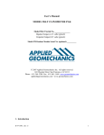
Model numbers for the SHA series actuators and how to interpret them are explained below.
Examples of standard models:
SHA
(1)
32
(2)
A
(3)
101
(4)
-
-
SG
(5)
B
(6)
12
(7)
A
(8)
200
(9)
-
-
10
(10)
S17b
(11)
A
(12)
-
-
C
(13)
(14)
- (15)
(1) Model: SHA series actuator
(2) Size: 20, 25, 32, 40, 58, 65:SG
25, 32:HP
20, 25, 32, 40:CG
(3) Version
(4) Reduction ratio (R:1)
Reduction ratio 11 is for the HPF hollow planetary speed reducer (Size 25, 32)
®
Reduction ratios 50 and higher are for the HarmonicDrive gears
HPF
11
SHG
11:1
SG
CG
51
51:1
50
50:1
81
81:1
80
80:1
101
101:1
100
100:1
121
121:1
120
120:1
161
161:1
160
160:1
®
HarmonicDrive SHG series
6
7
10
8
HarmonicDrive CSG series
Size:
58, 65
B
Size: 25, 32, 40
C
Size: 20
(7) Motor size
17-bit absolute encoder, 131,072
pulses/revolution
11
D250: Incremental encoder (size 25, 32, and 40)
Biss-C: Absolute encoder (size 25)
(12) Encoder phase angle: Phase difference between
induced voltage in motor phase U and absolute origin
A
0 degree
08
Size: 20
09
Size: 25
C
With standard connector
(for extension cables)
12
Size: 32
N
Without connector
15
Size: 40
21
Size: 58, 65
(8) Brake
L
With near origin and end limit sensors
Y
Side exiting cable
With stand (CG only)
Output shaft single revolution absolute
model (CG only)
V
B
With brake
S
200V
(100V is compatible with size 25 only)
11
付
(14) Option symbol
Without brake
200
10
(13) Connector specification
A
(9) Motor input voltage
9
S17b
(6) Motor version symbol
A
Conforming to A format, transmission rate: 2.5
Mbps, 1-on-1 connection
(11) Encoder type, resolution
®
100V
5
(10) Encoder format
HPF hollow shaft planetary
100
4
CSG
(5) Gearhead
HP
3
(Please contact us for option-compatible models.)
(15) Special specification
Blank
Standard product
SP
Special specification product
1-2
1-3 Drivers and extension cables
1
Outlines
2
1-3 Drivers and extension cables
The proper combination of SHA actuators, drivers, and extension cables are as follows:
3
4
9
SHA32A
REL Servo Drive
REL-230-18
REL-230-18
REL230-36
REL 230-40
HA-800 Standard
HA-800A3D/E -200
HA-800A3D/E-200
(HA-800A6D/E -100)
HA-800A6D/E -200
HA-800B3D/E -200
HA-800B3D/E -200
(HA-800B6D/E -100)
HA-800B6D/E -200
HA-800C3D/E -200
HA-800C3D/E -200
(HA-800C6D/E -100)
HA-800C6D/E -200
HA-800
MECHATROLINK
6
8
SHA25A
I/O command type
5
7
SHA20A
HA-800 CC-Link
Extension
cables
(option)
Motor
cable
EWD-MB**-A06-TN3
(Driver side connector
supplied separately)
SHA40A
HA-800A-6 D/E 200
or
HA-800A-24D/E 200
HA-800B-6D/E 200
or
HA-800B-24D/E 200
HA-800C-6D/E 200
or
HA-800C-24D/E 200
HA-800□-6D/E:
EWD-MB**-A06TN3
HA-800□-24D/E:
EWD-MB**-A06TMC
Encoder
EWD-S**-A08-3M14
cable
** in the extension cable model indicates the cable length: 03 = 3m, 05 = 5m, 10 = 10m
SHA58A
SHA65A
HA-800A24D/E -200
HA-800A24D/E 200
HA-800B24D/E -200
HA-800B24D/E 200
HA-800C24D/E -200
HA-800C24D/E 200
EWD-MB**-D09-TMC
EWD-S**-D10-3M14
The models shown in parenthesis are those with 100V motor input voltage combinations.
10
11
付
1-3
1-4 Specifications
1
Outlines
1-4 Specifications
2
SG type
51
81
Nm
kgf・m
Nm
kgf・m
rpm
Nm/A
kgf・m/A
A
73
7.4
21
2.1
117.6
16.5
1.7
6.0
96
9.8
35
3.6
74.1
27
2.7
4.9
SHA20A
101
REL-230-18
HA-800□-3D/E-200
107
10.9
43
4.4
59.4
33
3.4
4.5
A
2.1
2.0
2.0
1.9
1.6
V/(rpm)
1.9
3.0
3.7
4.5
5.9
1.3
13
1.4
15
121:1
2.3
24
2.6
26
161:1
Model
Item
Servo Drive
Max. torque*1
Allowable continuous
torque*1*2
Max. rotational speed*1
Torque constant*1
Max. current*1
Allowable continuous
current*1*2
EMF constant*3
Phase resistance
(20℃)
Phase inductance
2
GD /4
Inertia moment
(without brake)
J
2
GD /4
Inertia moment
(with brake)
J
Reduction ratio
Permissible
moment load
Moment stiffness
Ω
mH
2
kg・m
2
kgf・cm・s
2
kg・m
2
kgf・cm・s
Motor insulation
Mounting direction
Protection structure
161
113
11.5
48
4.9
49.6
40
4.1
4.0
120
12.2
48
4.9
37.3
53
5.4
3.4
3
4
5
6
1.4
0.23
2.4
0.26
2.6
51:1
0.58
6.0
0.65
6.6
81:1
Nm
kgf・m
Nm/rad
kgf・m/arc min
One-way positional
Sec.
accuracy
Encoder type
Single motor revolution
Encoder resolution
Motor multi revolution
counter
Output resolution
Pulse/rev
Mass
kg
(without brake)
Mass (with brake)
kg
Environmental conditions
121
60
2.5
0.91
9.3
1.0
10
101:1
187
19.1
4
25.2×10
7.5
50
50
7
8
9
50
50
10
Absolute encoder
17
2 (131,072)
16
2 (65,536)
6,684,672
10,616,832
13,238,272
15,859,712
21,102,592
11
2.0
2.1
Operating temperature: 0 to 40℃/Storage temperature: -20 to 60℃
Operating humidity/storage humidity: 20 to 80%RH (no condensation)
Resistance to vibration: 25 m/s2 (frequency: 10 to 400Hz)/Shock
resistance: 300 m/s2 *4
No dust, no metal powder, no corrosive gas, no inflammable gas, no
oil mist
To be used indoors, no direct sunlight
Altitude: less than 1,000 m above sea level
Insulation resistance: 100MΩ or more (by DC500V insulation tester)
Dielectric strength: AC1,500V/1 min
Insulation class: A
Can be installed in any direction.
Totally enclosed self-cooled type (IP54)
The table shows typical output values of actuators.
*1: Typical characteristics when combined (driven by ideal sine wave) with our drivers.
*2: Value after temperature rise and saturation when the 320 x 320 x 16 [mm] aluminum radiation plate is installed.
*3: Value of phase induced voltage constant multiplied by 3.
*4: For testing conditions, refer to [1-12 Shock resistance] (P1-42) and [1-13 Vibration resistance ] (P1-43).
1-4
付
1-4 Specifications
1
SG/HP type
Model
Item
Outlines
2
3
4
Max. torque*1
Allowable
continuous
torque*1*2
Max. rotational
speed*1
6
7
Max. current*1
Allowable
continuous
current*1*2
EMF constant*3
Phase resistance
(20℃)
Phase inductance
GD2/4
Inertia moment
(without brake)
J
2
8
9
Inertia moment
(with brake)
GD /4
J
Reduction ratio
Permissible
moment load
Moment stiffness
10
11
付
11
51
81
101
121
REL-230-18
REL-230-36
HA-800□-3D/E-200
127
13
35
178
18.2
58
204
20.8
73
217
22.1
81
229
23.4
81
26
2.7
9.0
127
13
41
178
18.2
67
204
20.8
81
217
22.1
81
229
23.4
81
kgf・m
3.6
5.9
7.4
8.2
8.2
0.92
4.2
6.8
8.2
8.2
8.2
rpm
94.1
59.3
47.5
39.7
29.8
509.1
109.8
69.1
55.4
46.3
34.8
Nm/A
kgf・m/A
A
11.1
1.1
14.9
17.9
1.8
13.0
22
2.3
12.1
27
2.7
10.9
36
3.6
9.0
4.2
0.43
8.9
19
2.0
8.6
31
3.2
7.5
39
4.0
7.0
46
4.7
6.3
62
6.3
5.2
A
4.7
4.7
4.7
4.5
3.7
3.0
3.0
3.0
2.9
2.6
2.1
V/(rpm)
1.3
2.0
2.5
3.0
4.0
0.47
2.2
3.5
4.3
5.2
6.9
Ω
mH
kg・m2
kgf・cm・
s2
kg・m2
kgf・cm・
s2
0.4
1.4
1.0
2.2
3.2
5.6
0.029
0.56
1.4
2.2
3.2
5.6
5.7
14
22
32
57
0.30
5.7
14
22
32
57
0.66
1.7
2.6
3.7
6.6
0.034
0.66
1.7
2.6
3.7
6.6
6.7
17
26
38
67
0.35
6.7
17
26
38
67
1:51
1:81
1:101
258
26.3
1:121
1:161
1:11
410
41.8
37.9
x 104
1:51
1:81
1:101
258
26.3
1:121
1:161
Nm/rad
39.2 x 10⁴
kgf・
m/arc
min
11.6
Pulse/rev
Motor insulation
Mounting direction
Protection structure
1.2
0.56
Nm
kgf・m
Mass
kg
(without brake)
Mass (with brake)
kg
Environmental conditions
50
40
40
3
39.2 x 10⁴
11.3
40
40
120
11.6
50
40
40
40
40
10,616,
832
13,238,
272
15,859,
712
21,102,
592
Magnetic absolute encoder
217(131,072)
216(65,536)
6,684,
672
10,61
6,
832
13,238,
272
15,859,
712
21,102,
592
1,441,
792
6,684,
672
2.95
5.0
2.95
3.1
5.1
3.1
Operating temperature: 0 to 40℃/Storage temperature: -20 to 60℃
Operating humidity/storage humidity: 20 to 80%RH (no condensation)
Resistance to vibration: 25 m/s2 (frequency: 10 to 400Hz)/Shock resistance: 300 m/s2 *4
No dust, no metal powder, no corrosive gas, no inflammable gas, no oil mist
To be used indoors, no direct sunlight
Altitude: less than 1,000 m above sea level
Insulation resistance: 100MΩ or more (by DC500V insulation tester)
Dielectric strength: AC1,500V/1 min
Insulation class: A
Can be installed in any direction.
Totally enclosed self-cooled type (IP54)
The table shows typical output values of actuators.
*1: When combined with a HA-800 driver..
*2: Value after temperature rise and saturation when the 350 x 350 x 18 [mm] aluminum radiation plate is installed.
*3: Value of phase induced voltage constant multiplied by 3.
*4: For testing conditions, refer to [1-12 Shock resistance] (P1-42) and [1-13 Vibration resistance ] (P1-43).
1-5
161
Nm
kgf・m
Nm
One-way positional
Sec.
accuracy
Encoder type
Single motor revolution
Encoder resolution
Motor multi revolution counter
Output resolution
SHA25A (Motor input voltage 200V)
REL-230-18
HA-800□-6D/E-100
Servo Drive
Torque constant*1
5
SHA25A
(Motor input voltage 100V)
51
81
101
121
161
1-4 Specifications
SG/HP type
Model
Item
11
51
161
Outlines
2
Nm
kgf・m
Nm
62
6.3
20
281
28.7
92
395
40.3
153
433
44.2
178
459
46.8
178
484
49.4
178
kgf・m
2.1
9.4
15.6
18.2
18.2
18.2
r/min
436.4
94.1
59.3
47.5
39.7
29.8
Nm/A
kgf・m/A
A
4.5
0.46
19
21
2.1
17.3
33
3.4
15.2
42
4.2
13.5
50
5.1
12.2
66
6.8
9.9
4
A
6.0
6.0
6.0
5.7
5.0
4.1
5
V/(r/min)
0.51
2.3
3.7
4.7
5.6
7.4
Allowable
continuous
torque*1*2
Max. rotational
speed*1
Moment stiffness
1
121
HA-800□-6D/E-200
Max. torque*1
Max. current*1
Allowable
continuous
current*1*2
EMF constant*3
Phase resistance
(20℃)
Phase inductance
Inertia
GD2/4
moment
(without
J
brake)
Inertia
GD2/4
moment
(with
J
brake)
Reduction ratio
Permissible
moment load
SHA32A
101
REL-230-18, REL-230-36
Servo Drive
Torque constant*1
81
Ω
mH
kg・m2
One-way positional
accuracy
0.33
6
1.4
0.091
2.0
5.1
8.0
11
20
kgf・
cm・s2
0.93
21
52
81
117
207
kg・m2
0.11
2.3
5.9
9.2
13
23
kgf・
cm・s2
1.1
24
60
94
135
238
1:11
932
95
86.1 x 10⁴
1:51
1:81
1:121
1:161
Nm
kgf・m
Nm/rad
kgf・
m/arc
min
Sec.
Encoder type
Single motor
revolution
Encoder resolution
Motor multi
revolution counter
Output resolution
Pulse/rev
Mass
kg
(without brake)
Mass (with brake)
kg
Environmental conditions
Motor insulation
Mounting direction
Protection structure
3
25.7
120
1:101
580
59.1
100 x 104
7
8
9
29.6
50
40
40
40
10
40
Magnetic absolute encoder
11
217(131,072)
216(65,536)
1,441,792
9.4
6,684,672
10,616,832
13,238,272
15,859,712
付
21,102,592
5.9
9.7
6.2
Operating temperature: 0 to 40℃/Storage temperature: -20 to 60℃
Operating humidity/storage humidity: 20 to 80%RH (no condensation)
Resistance to vibration: 25 m/s2 (frequency: 10 to 400Hz)/Shock
resistance: 300 m/s2 *4
No dust, no metal powder, no corrosive gas, no inflammable gas, no oil mist
To be used indoors, no direct sunlight
Altitude: less than 1,000 m above sea level
Insulation resistance: 100MΩ or more (by DC500V insulation tester)
Dielectric strength: AC1,500V/1 min
Insulation class: A
Can be installed in any direction.
Totally enclosed self-cooled type (IP54)
The table shows typical output values of actuators.
*1: When combined with a HA-800 driver..
*2: Value after temperature rise and saturation when the 400 x 400 x 20 [mm] aluminum radiation plate is installed.
*3: Value of phase induced voltage constant multiplied by 3.
*4: For testing conditions, refer to [1-12 Shock resistance] (P1-42) and [1-13 Vibration resistance ] (P1-43).
1-6
1-4 Specifications
1
SG type
Model
Outlines
Item
2
3
4
5
6
7
8
9
10
11
付
51
Allowable
continuous
torque*2*3
Max. rotational
speed*2
Torque constant*2
121
SHA40A
161
51
81
101
121
REL-230-36, REL-230-40
HA-800□-24D/E-200
340
34.7
94
560
57.1
158
686
70
198
802
81.8
237
841
85.8
317
523
53.4
160
675
68.9
263
738
75.3
330
802
81.8
382
841
85.8
382
kgf・m
9.6
16.1
20.2
24.2
32.3
16.3
26.8
33.7
39
39
r/min
78.4
49.4
39.6
33.1
24.8
78.4
49.4
39.6
33.1
24.8
Nm/A
kgf・m/A
A
25
2.6
18
41
4.1
18
51
5.2
18
61
6.2
17.9
81
8.2
14.6
25
2.6
26.7
41
4.1
21.8
51
5.2
19.4
61
6.2
17.9
81
8.2
14.6
6.0
6.0
6.0
6.0
6.0
9.0
9.0
9.0
8.8
7.2
2.9
4.6
5.7
6.8
9.1
2.9
4.6
5.7
6.8
9.1
Pulse/rev
Mass
kg
(without brake)
Mass (with brake)
kg
Environmental conditions
Motor insulation
Mounting direction
Protection structure
0.19
1.2
5.0
13
20
28
50
5.0
13
20
28
50
51
130
202
290
513
51
130
202
290
513
6.1
15
24
34
61
6.1
15
24
34
61
62
157
244
350
619
62
157
244
350
619
1:51
1:81
1:101
1:121
1:81
1:101
1:121
1:161
40
40
40
40
13,23
8,272
15,859,
712
21,102,
592
1:161
1:51
849
86.6
179 x 104
53.2
50
40
40
40
40
50
Magnetic absolute encoder
217(131,072)
216(65,536)
6,684,
672
10,616,
832
13,238,
272
15,859,
712
21,102,
592
6,684
,672
10,616
,832
9.9
10.7
Operating temperature: 0 to 40℃/Storage temperature: -20 to 60℃
Operating humidity/storage humidity: 20 to 80%RH (no condensation)
Resistance to vibration: 25 m/s2 (frequency: 10 to 400Hz)/Shock resistance: 300 m/s2 *5
No dust, no metal powder, no corrosive gas, no inflammable gas, no oil mist
To be used indoors, no direct sunlight
Altitude: less than 1,000 m above sea level
Insulation resistance: 100MΩ or more (by DC500V insulation tester)
Dielectric strength: AC1,500V/1 min
Insulation class: A
Can be installed in any direction.
Totally enclosed self-cooled type (IP54)
The table shows typical output values of actuators.
*1: If a HA-800□-6D/E driver is combined with a SHA40A actuator, the maximum torque and allowable continuous torque are limited.
*2: When combined with HA-800 driver. .
*3: Value after temperature rise and saturation when the 500 x 500 x 25 [mm] aluminum radiation plate is installed.
*4: Value of phase induced voltage constant multiplied by 3.
*5: For testing conditions, refer to [1-12 Shock resistance] (P1-42) and [1-13 Vibration resistance ] (P1-43).
1-7
161
Nm
kgf・m
Nm
Max. current*2
Allowable
continuous
A
current*2*3
EMF constant*4
V/(r/min)
Phase resistance
Ω
(20℃)
Phase inductance
mH
Inertia
GD2/4 kg・m2
moment
kgf・
(without
J
cm・s2
brake)
GD2/4 kg・m2
Inertia
moment
kgf・
J
(with brake)
cm・s2
Reduction ratio
Nm
Permissible
moment load
kgf・m
Nm/rad
kgf・
Moment stiffness
m/arc
min
One-way positional
Sec.
accuracy
Encoder type
Single motor revolution
Encoder resolution
Motor multi revolution
counter
Output resolution
101
HA-800□-6D/E-200*1
Servo Drive
Max. torque*2
81
1-4 Specifications
1
SG type
Model
81
Servo Drive
Max. torque*1
Allowable
continuous
torque*1*2
Max. rotational
speed*1
Torque constant*1
161
81
SHA65A
101
121
HA-800□-24D/E-200
161
Outlines
Item
SHA58A
101
121
HA-800□-24D/E-200
2
Nm
kgf・m
Nm
1924
196
714
2067
211
905
2236
228
969
2392
244
969
2400
245
921
2990
305
1149
3263
333
1236
3419
349
1236
kgf・m
73
92
99
99
94
117
126
126
rpm
37.0
29.7
24.8
18.6
34.6
27.7
23.1
17.4
Nm/A
kgf・m/A
A
54
5.5
45
68
6.9
39
81
8.3
36
108
11.0
30
54
5.5
55
68
6.9
55
81
8.3
51
108
11.0
41
4
17.7
17.8
16.4
13.4
22.0
21.9
20.1
16.3
6.1
7.6
9.1
12.1
6.1
7.6
9.1
12.1
5
Max. current*1
Allowable
continuous
A
current*1*2
EMF constant*3
V/(rpm)
Phase resistance
Ω
(20℃)
Phase inductance
mH
Inertia
GD2/4 kg・m2
moment
kgf・
(without
J
cm・s2
brake)
Inertia
GD2/4 kg・m2
moment
kgf・
(with
J
cm・s2
brake)
Reduction ratio
Nm
Permissible
moment load
kgf・m
Nm/rad
kgf・
Moment stiffness
m/arc
min
One-way positional
Sec.
accuracy
Encoder type
Single motor revolution
Encoder resolution
Output resolution Pulse/rev
Mass
kg
(without brake)
Mass (with brake)
kg
Environmental conditions
Motor insulation
Mounting direction
Protection structure
0.028
0.028
0.29
149
214
379
110
171
245
433
980
1520
2180
3870
1120
1740
2500
4420
106
165
237
420
120
187
268
475
1090
1690
2420
4290
1230
1910
2740
4850
1:81
1:101
1:121
2180
222
531 x 104
1:161
1:81
1:101
1:121
2740
280
741 x 104
1:161
158
40
6
0.29
96
40
3
7
8
9
220
40
40
40
40
40
10
15,859,712
21,102,592
11
40
Magnetic absolute encoder
217(131,072)
10,616,832
13,238,272
15,859,712
21,102,592
10,616,832
13,238,272
29.5
37.5
32
40
Operating temperature: 0 to 40℃/Storage temperature: -20 to 60℃
Operating humidity/storage humidity: 20 to 80%RH (no condensation)
Resistance to vibration: 25 m/s2 (frequency: 10 to 400Hz)/Shock resistance: 300
m/s2 *4
No dust, no metal powder, no corrosive gas, no inflammable gas, no oil mist
To be used indoors, no direct sunlight
Altitude: less than 1,000 m above sea level
Insulation resistance: 100MΩ or more (by DC500V insulation tester)
Dielectric strength: AC1,500V/1 min
Insulation class: A
Can be installed in any direction.
Totally enclosed self-cooled type (IP54)
The table shows typical output values of actuators.
*1: When combined with HA-800 driver.
*2: Value after temperature rise and saturation when the 650 x 650 x 30 [mm] aluminum radiation plate is installed.
*3: Value of phase induced voltage constant multiplied by 3.
*4: For testing conditions, refer to [1-12 Shock resistance] (P1-42) and [1-13 Vibration resistance ] (P1-43).
1-8
付
1-4 Specifications
1
CG type
Outlines
4
5
6
7
8
Max. torque
120
12.2
48
4.9
120
75
60
50
37.5
Nm/A
kgf・m/A
A
16
1.7
6.1
26
2.7
5.0
33
3.4
4.6
39
4.0
4.1
53
5.4
3.4
A
2.1
2.1
2.1
2.0
1.7
V/(rpm)
1.8
2.9
3.7
4.4
5.9
Allowable
*1*2
continuous torque
Max. rotational
*1
speed
Torque constant
*1
Max. current*1
Allowable continuous
current*1*2
EMF constant*3
Phase resistance
(20℃)
Phase inductance
Inertia
GD2/4
moment
(without
J
brake)
Inertia
GD2/4
moment
(with
J
brake)
Reduction ratio
Permissible moment
load
Moment stiffness
10
One-way positional
accuracy
Repeatability
Bi-directional
repeatability
付
113
11.5
48
4.9
*1
9
11
160
50
80
Nm
kgf・m
Nm
kgf・m
73
7.4
21
2.1
r/min
Servo Drive
2
3
120
96
9.8
35
3.6
SHA20A
100
REL-230-18
HA-800□-3D/E-200
107
10.9
43
4.4
Actuator Model
Item
Ω
1.4
mH
2
kg・m
kgf・cm・s
kg・m
2
2
kgf・cm・s
2
0.21
0.53
2.5
0.82
1.2
2.1
2.1
5.4
8.0
12
22
0.23
0.60
0.94
1.3
2.4
2.4
6.1
9.6
14
24
1:50
1:80
1:100
187
19.1
4
25.2×10
1:120
1:160
50
50
30
30
15,728,640
20,971,520
Nm
kgf・m
Nm/rad
kgf・m/arc
min
Sec
7.5
60
50
50
±5
Sec
Sec
Encoder type
Single motor revolution
Encoder resolution
Motor multi revolution counter
Output resolution
Pulse/rev
Mass
kg
(without brake)
Mass (with brake)
kg
Environmental conditions
Motor insulation
Mounting direction
Protection structure
75
30
30
Magnetic absolute encoder
17
2 (131,072)
16
6,553,600
10,485,760
2 (65,536)
13,107200
2.6
2.7
Operating temperature: 0 to 40℃/Storage temperature: -20 to 60℃
Operating humidity/storage humidity: 20 to 80%RH (no condensation)
Resistance to vibration: 25 m/s2 (frequency: 10 to 400Hz)/Shock resistance: 300
m/s2 *4
No dust, no metal powder, no corrosive gas, no inflammable gas, no oil mist
To be used indoors, no direct sunlight
Altitude: less than 1,000 m above sea level
Insulation resistance: 100MΩ or more (by DC500V insulation tester)
Dielectric strength: AC1,500V/1 min
Insulation class: A
Can be installed in any direction
Totally enclosed self-cooled type (IP54)
The table shows typical output values of actuators.
*1: Typical characteristics when combined with our HA-800 driver.
*2: Value after temperature rise and saturation when the 350 x 350 x 18 [mm] aluminum radiation plate is installed.
*3: Value of phase induced voltage constant multiplied by 3.
*4: For testing conditions, refer to [1-12 Shock resistance] (P1-42) and [1-13 Vibration resistance ] (P1-43).
1-9
1-4 Specifications
CG type
Model
Sevo Drive
Max. torque
*1
Allowable
*1*2
continuous torque
Max. rotational
*1
speed
Torque constant
*1
Max. current*1
Allowable continuous
current*1*2
EMF constant*3
Phase resistance
(20℃)
Phase inductance
Inertia
GD2/4
moment
(without
J
brake)
GD2/4
Inertia
moment
J
(with brake)
Reduction ratio
Permissible moment
load
Moment stiffness
One-way positional
accuracy
Repeatability
Bi-directional
positional accuracy
Nm
kgf・m
Nm
kgf・m
r/min
96
60
48
40
30
112
70
56
46.7
35
Nm/A
kgf・m/A
A
10.9
1.1
15.1
17.7
1.8
13.2
22
2.3
12.2
27
2.7
11.0
35
3.6
9.0
19
1.9
8.7
31
3.1
7.6
38
3.9
7.0
46
4.7
6.3
61
6.3
5.2
A
4.7
4.7
4.7
4.5
3.7
3.0
3.0
3.0
2.6
2.1
V/(rpm)
1.2
2.0
2.5
3.0
4.0
2.1
3.4
4.3
5.2
6.9
0.4
1.2
mH
2
kg・m
2.9
5.1
0.50
1.3
3.0
2.0
2.9
5.1
0.50
1.3
1.0
2.0
5.1
13
20
29
52
5.1
13
20
29
52
kg・m
kgf・cm・
2
s
mH
Nm
kgf・m
Nm/rad
kgf・
m/arc
min
0.60
1.5
2.4
3.4
6.1
0.60
1.5
2.4
3.4
6.1
6.1
16
24
35
62
6.1
16
24
35
62
50:1
80:1
120:1
1:120
80:1
120:1
Sec
50
kgf・cm・
2
s
2
Mass
(without brake)
Mass (with brake)
160:1
50:1
258
26.3
4
39.2×10
Pulse/rev
2
3
4
5
7
8
1:120 160:1
9
11.6
40
40
40
40
50
40
40
40
40
60
25
25
25
25
10
±5
Sec
Sec
1
6
Ω
60
25
25
Encoder type
Single motor revolution
Encoder resolution
Motor multi revolution counter
Output resolution
SHA25A(Motor input voltage 200V)
50
80
100
120
160
REL-230-18
REL-230-36
HA-800□-3D/E-200
127
178
204
217
229
13
18.2
20.8
22.1
23.4
40
66
81
81
81
4.1
6.8
8.2
8.2
8.2
Outlines
Item
SHA25A(Motor input voltage 100V)
50
80
100
120
160
REL-230-18
REL-230-36
*1
HA-800□-6D/E-100
127
178
204
217
229
13
18.2
20.8
22.1
23.4
34
57
72
81
81
3.5
5.8
7.3
8.2
8.2
25
25
11
Magnetic absolute encoder
17
2 (131,072)
付
16
2 (65,536)
6,553,
600
10,485,
760
13,107,
200
15,728,
640
20,971,
520
6,553,
600
kg
3.95
kg
4.1
10,485,
760
13,107,
200
15,728,
640
20,971
,520
1-10
1-4 Specifications
1
Environmental conditions
Outlines
2
Motor insulation
3
4
5
Operating temperature: 0 to 40℃/Storage temperature: -20 to 60℃
Operating humidity/storage humidity: 20 to 80%RH (no condensation)
Resistance to vibration: 25 m/s2 (frequency: 10 to 400Hz)/Shock resistance: 300 m/s2 *4
No dust, no metal powder, no corrosive gas, no inflammable gas, no oil mist
To be used indoors, no direct sunlight
Altitude: less than 1,000 m above sea level
Insulation resistance: 100MΩ or more (by DC500V insulation tester)
Dielectric strength: AC1,500V/1 min
Insulation class: A
Can be installed in any direction
Mounting direction
Totally enclosed self-cooled type (IP54)
Protection structure
The table shows typical output values of actuators.
*1: Typical characteristics when combined (driven by ideal sine wave) with our drivers.
*2: Value after temperature rise and saturation when the 350 x 350 x 18 [mm] aluminum radiation plate is installed.
*3: Value of phase induced voltage constant multiplied by 3.
*4: For testing conditions, refer to [1-12 Shock resistance] (P1-42) and [1-13 Vibration resistance ] (P1-43).
6
7
8
9
10
11
付
1-11
1-4 Specifications
CG type
SHA32A
100
Model
Item
50
80
Allowable continuous
*1*2
torque
*1
Max. rotational speed
Torque constant
*1
*1
Max. current
Allowable continuous
*1*2
current
*3
EMF constant
Phase resistance
(20℃)
*1
Max. current
2
Inertia
GD /4
moment
(without
J
brake)
2
Inertia
GD /4
moment
(with
J
brake)
Reduction ratio
Permissible moment
load
Moment stiffness
One-way positional
accuracy
Repeatability
Bi-directional
repeatability
Encoder type
Single motor
revolution
Encoder resolution
Motor multi revolution
counter
Output resolution
Mass
(without brake)
Mass (with brake)
459
46.8
178
18.2
40
49
5.0
12.2
484
49.4
178
18.2
30
66
6.7
10
1
HA-800□-6D/E-200
433
44.2
178
18.2
48
41
4.2
13.7
Outlines
Max. torque
160
REL-230-18
REL-230-36
Servo Drive
*1
120
2
Nm
kgf・m
Nm
kgf・m
r/min
Nm/A
kgf・m/A
A
281
28.7
90
9.2
96
20
2.1
17.7
395
40.3
151
15.4
60
33
3.4
15.4
A
6.0
6.0
5.7
5.0
4.1
V/(rpm)
2.3
3.7
4.6
5.5
7.4
5
6
Ω
4
0.33
mH
2
kg・m
kgf・cm・
2
s
kg・m
3
2
kgf・cm・
2
s
1.7
4.3
1.4
6.7
9.7
17
17
44
68
99
175
2.0
5.1
7.9
11
20
20
52
81
116
207
50:1
80:1
120:1
160:1
100:1
580
59.2
4
100×10
Nm
kgf・m
Nm/rad
kgf・
m/arc
min
Sec
8
9
29.6
40
30
30
Sec
Sec
7
30
30
25
25
10
±4
60
25
25
11
Magnetic absolute encoder
17
2 (131,072)
付
16
2 (65,536)
Pulse/rev
6,553,600
10,485,760
13,107,200
kg
7.7
kg
8.0
15,728,640
20,971,520
1-12
1-4 Specifications
1
Environmental conditions
Outlines
2
Motor insulation
3
4
5
Operating temperature: 0 to 40℃/Storage temperature: -20 to 60℃
Operating humidity/storage humidity: 20 to 80%RH (no condensation)
Resistance to vibration: 25 m/s2 (frequency: 10 to 400Hz)/Shock resistance:
300 m/s2 *4
No dust, no metal powder, no corrosive gas, no inflammable gas, no oil mist
To be used indoors, no direct sunlight
Altitude: less than 1,000 m above sea level
Insulation resistance: 100MΩ or more (by DC500V insulation tester)
Dielectric strength: AC1,500V/1 min
Insulation class: A
Can be installed in any direction.
Mounting direction
Totally enclosed self-cooled type (IP54)
Protection structure
The table shows typical output values of actuators.
*1: Typical characteristics when used with HA-800.
*2: Value after temperature rise and saturation when the 400 x 400 x 20 [mm] aluminum radiation plate is installed.
*3: Value of phase induced voltage constant multiplied by 3.
*4: For testing conditions, refer to [1-12 Shock resistance] (P1-42) and [1-13 Vibration resistance ] (P1-43).
6
7
8
9
10
11
付
1-13
1-4 Specifications
CG type
Model
Item
50
Max. torque
*2
Allowable
continuous
*2*3
torque
Max. rotational
*2
speed
Torque constant
*2
*1
Max. current
Allowable
continuous
*1*2
current
EMF constant
Phase resistance
(20℃)
Phase inductance
2
Inertia
GD /4
moment
(without
J
brake)
2
Inertia
GD /4
moment
(with
J
brake)
Reduction ratio
Permissible moment
load
Moment stiffness
One-way positional
accuracy
Repeatability
Bi-directional
repeatability
Encoder type
Single motor
revolution
Encoder resolution
Motor multi
revolution counte
Output resolution
Mass
(without brake)
Mass (with brake)
100
120
HA-800□-6D/E-200
SHA40A
160
50
80
100
120
160
REL-230-36, REL-230-40
*1
Nm
kgf・m
Nm
333
34.0
92
548
55.9
156
686
70.0
196
802
81.8
235
841
85.8
315
523
53.4
157
HA-800□-24D/E-200
675
738
802
68.9
75.3
81.8
260
327
382
kgf・m
9.4
15.9
20.0
24.0
32.1
16.0
26.5
33.3
39
39
rpm
80
50
40
33.3
25
80
50
40
33.3
25
Nm/A
kgf・
m/A
A
25
40
50
60
80
25
40
50
60
80
2.5
4.1
5.1
6.1
8.2
2.5
4.1
5.1
6.1
8.2
18
18
18
17.6
14.3
27.2
22
19.6
18
14.7
A
6.0
6.0
6.0
6.0
6.0
9.0
9.0
9.0
8.8
7.2
V/(rpm)
2.8
4.5
5.6
6.7
9.0
2.8
4.5
5.6
6.7
9.0
Ω
kgf・
2
cm・s
2
kgf・
2
cm・s
12
19
27
49
4.8
12
19
27
49
49
124
194
280
497
49
124
194
280
497
5.8
15
23
33
59
5.8
15
23
33
59
59
150
235
338
601
59
150
235
338
601
50:1
80:1
100:1
120:1
80:1
100:1
120:1
160:1
160:1 50:1
849
86.6
4
179×10
5
40
30
30
30
30
40
30
30
30
20
20
20
11
20
50
20
20
20
20
付
17
2 (131,072)
16
2 (65,536)
6,553,
600
10,485,
760
13,107,
200
15,728,
640
20,971,
520
8
30
±4
50
7
10
Magnetic absolute encoder
Pulse/re
v
4
9
53.2
Sec
Sec
3
1.2
4.8
Nm
kgf・m
Nm/rad
kgf・
m/arc
min
Sec
2
6
0.19
mH
2
kg・m
kg・m
841
85.8
382
1
Outlines
Combined driver
80
6,553,
600
kg
13.0
kg
13.8
10,485,
760
13,107,
200
15,728,
640
20,971,
520
1-14
1-4 Specifications
1
Environmental conditions
Outlines
2
3
4
5
Motor insulation
Operating temperature: 0 to 40℃/Storage temperature: -20 to 60℃
Operating humidity/storage humidity: 20 to 80%RH (no condensation)
Resistance to vibration: 25 m/s2 (frequency: 10 to 400Hz)/Shock resistance: 300 m/s2 *4
No dust, no metal powder, no corrosive gas, no inflammable gas, no oil mist
To be used indoors, no direct sunlight
Altitude: less than 1,000 m above sea level
Insulation resistance: 100MΩ or more (by DC500V insulation tester)
Dielectric strength: AC1,500V/1 min
Insulation class: A
Can be installed in any direction.
Mounting direction
Totally enclosed self-cooled type (IP54)
Protection structure
The table shows typical output values of actuators.
*1: If a HA-800□ -6D/E driver is combined with a SHA40A actuator, the maximum torque and allowable
continuous torque are limited.
*2: Typical characteristics when combined (driven by ideal sine wave) with our drivers.
*3: Value after temperature rise and saturation when the 500 x 500 x 25 [mm] aluminum radiation plate is installed.
*4: Value of phase induced voltage constant multiplied by 3.
*5: For testing conditions, refer to [1-12 Shock resistance] (P1-42) and [1-13 Vibration resistance ] (P1-43).
6
7
8
9
10
11
付
1-15
1-5 Motor shaft brake
1
The brake is used to hold the motor shaft in place when the power is turned off. With smaller sizes (SHA25A,
32A), the actuator's built-in circuit controls the voltage supplied to the brake in order to reduce the power
consumption while the brake is actuated.
Be sure to use a DC power supply having proper brake excitation voltage and capable of outputting enough
current for the brake actuation (release).
Outlines
1-5 Motor shaft brake
2
3
Specifications
SG/HP type
Model
4
SHA20A
Item
51
81
101
121
161
Dry non-excitation actuation type (without powersaving control)
Type
Brake excitation
voltage
Current
consumption
during suction
(at 20℃)
Current
consumption
during holding
(at 20℃)
Holding torque*3
Inertia moment*3
(Actuator total)
(with brake)
Mass (with brake)*4
V
DC24V ± 10% (no polarity)*1
A
0.37
A
Same as current consumption during suction
6
Nm
31
49
61
73
97
kgf·m
3.1
5.0
6.2
7.4
9.9
0.26
0.65
1.0
1.4
2.6
2.7
6.6
10
15
26
(GD2/4)
kg·m2
(J)
kgf·cm·s2
kg
5
7
8
2.1
Allowable number
of normal stops*5
Allowable number
of emergency
stops*6
100,000 times
9
200 times
SHA25A
Model
Item
11
51
81
Type
101
10
SHA32A
121
161
11
51
81
101
121
161
Dry non-excitation actuation type (with power-saving control)
Brake excitation
voltage
Current
consumption
during suction
(at 20℃)
Current
consumption
during holding
(at 20℃)
Holding torque*3
*3
Inertia moment
(Actuator total)
(with brake)
Mass (with brake)
*4
Allowable number
of normal stops*5
Allowable number
of emergency
stops*6
11
DC24V ± 10% (no polarity)*1
V
0.8*2
A
0.8*2
付
A
0.3
0.3
Nm
11
51
81
101
121
161
22
102
162
202
242
322
kgf·m
1.1
5.2
8.3
10
12
16
2.2
10
17
21
25
33
0.034
0.66
1.7
2.6
3.7
6.6
1.7
2.3
5.9
9.2
13
23
0.35
6.7
17
26
38
67
17
24
60
94
135
238
(GD2/4)
kg·m2
(J)
kgf·cm·s2
kg
5.1
3.1
9.7
6.2
100,000 times
200 times
1-16
1-5 Motor shaft brake
1
Outlines
2
Model
Item
51
Type
Brake excitation voltage
Current consumption
during suction (at 20℃)
Current consumption
during holding (at 20℃)
3
*3
Inertia moment
(Actuator total)
(With brake)
*4
4
5
V
A
A
Mass (with brake)
Allowable number of
*5
normal stops
Allowable number of
*6
emergency stops
Model
Brake excitation voltage
Current consumption
during suction (at 20℃)
Current consumption
during holding (at 20℃)
Holding torque*3
Inertia moment*3
(Actuator total)
(With brake)
8
9
Mass (with brake)*4
Allowable number of
normal stops*5
Allowable number of
emergency stops*6
Same as current consumption during suction
204
21
324
33
404
41
484
49
644
66
1220
124
1520
155
1820
185
2420
246
6.1
15
24
34
61
106
165
237
420
62
157
244
350
619
1090
1690
2420
4290
10.7
V
A
0.9
Same as current consumption during
suction
1220
1520
1820
2420
124
155
185
246
A
Nm
kgf·m
(GD2/4)
kg·m2
(J)
kgf·cm·s2
kg
120
187
1230
1910
268
475
2740
4850
40
100,000 times
200 times
CG type
Model
10
付
32
SHA65A
81
101
121
161
Dry non-excitation actuation type (without
power-saving control)
DC24V±10% (no polarity)*1
SHA20A
Item
11
0.9
200 times
Item
7
161
100,000 times
Type
6
0.7
Nm
kgf·m
2
(GD /4)
2
kg·m
(J)
2
kgf·cm·s
kg
Holding torque*3
SHA40A
SHA58A
101
121
161
81
101
121
Dry non-excitation actuation type (without power-saving control)
DC24V ± 10% (no polarity)*1
81
Type
Brake excitation
voltage
Current consumption
during suction (at
20℃)
Current consumption
during holding (at
20℃)
Holding torque*3
*3
Inertia moment
(Actuator total)
(With brake)
Mass (with brake)
*4
Allowable number of
normal stops*5
Allowable number of
emergency stops*6
1-17
SHA25A
50
80
100
120
160
Dry non-excitation actuation type (without powersaving control)
50
80
100
120
160
Dry non-excitation actuation type (with powersaving control)
DC24V±10%(no polarity)*1
V
A
0.37
0.8 *2
A
Same as current consumption during suction
0.3
Nm
30
48
60
72
96
50
80
100
120
160
kgf·m
3.1
4.9
6.1
7.3
9.8
5.1
8.2
10
12
16
0.23
0.6
0.94
1.3
2.4
0.60
1.5
2.4
3.4
6.1
2.4
6.1
9.6
14
24
6.1
16
24
35
62
(GD2/4)
kg·m2
(J)
kgf·cm·s2
kg
2.7
4.1
100,000 times
200 times
1-5 Motor shaft brake
Model
SHA32A
Item
50
80
100
160
50
Brake excitation
voltage
Current consumption
during suction (at
20℃)
Current consumption
during holding (at
20℃)
Holding torque*3
80
100
120
160
0.7
Outlines
Dry non-excitation actuation type (with powersaving control)
Type
1
SHA40A
120
Same as current consumption during suction
3
Dry non-excitation actuation type (without
power-saving control)
DC24V±10%(no polarity)*1
V
A
0.8
A
*2
0.3
Nm
100
160
200
240
320
200
320
400
480
640
kgf·m
10
16
20
24
33
20
33
41
49
65
2.0
5.1
7.9
11
20
5.8
15
23
33
59
20
52
81
116
207
59
150
235
338
601
2
(GD /4)
2
kg·m
(J)
kgf·cm·s2
*3
Inertia moment
(Actuator total)
(With brake)
*4
Mass (with brake)
kg
Allowable number of
normal stops*5
Allowable number of
*6
emergency stops
8.0
13.8
4
5
100,000 times
200 times
6
*1: Power supply is user’s responsibility. Use a power supply capable of outputting enough current consumption during suction
for the brake.
*2: The duration for current consumption during suction is 0.5 second or less for the power supply of DC24V ± 10%.
*3: The values are converted for the output shaft of the actuator.
*4: The values present total mass of the actuator.
*5: The service time for normal holding is assured when the brake activates at motor shaft rotation speed of 150 rpm or less.
*6: The service time for emergency stop is assured when the brake activates at motor speed of 3,000 rpm or less provided the
load inertia moment is 3 times of less than that of the actuator.
The motor shaft holding brake cannot be used for deceleration.
WARNING
2
Do not use the holding brake more than the allowable number of normal
brakings (100,000 times at the motor shaft rotation speed of 150 rpm or less) or
allowable number of emergency stops (200 times with the motor shaft rotation
speed of 3,000 rpm, provided the load inertia moment is 3 times or less than
that of the actuator).
Exceeding the allowable number of normal stops or allowable number of
emergency stops may deteriorate holding torque, and may consequently fail to
properly serve as a brake.
7
8
9
10
11
付
1-18
1
Outlines
4
5
6
7
8
9
10
11
付
Note: The dimension tolerances that are not specified vary depending on the manufacturing method. Please check the
confirmation drawing or contact us for dimension tolerances not shown
1-6 External dimensions
1-6 External dimensions
2
SHA20A-SG
3
Unit: mm
1-19
Jacking
holes
Depth 7
LipC0.5 chamfering
or less
or less
or less
Encoder connector
Cable outer
diameter
4-core
Motor cable
Tab contact
Housing
Note: The dimension tolerances that are not specified vary depending on the manufacturing method. Please check the
confirmation drawing or contact us for dimension tolerances not shown
Output rotary unit
Motor connector
Encoder cable
AWG28 x 3 sets
with shield
Cable outer
diameter
SHA20A-CG
Outlines
Housing
Pin contact (Motor
Pin contact (Motor
1-6 External dimensions
Unit: mm
1
2
3
4
5
6
7
8
9
10
11
付
1-20
1
Outlines
3
4
5
6
7
8
9
10
11
付
Note: The dimension tolerances that are not specified vary depending on the manufacturing method. Please check the confirmation
drawing or contact us for dimension tolerances not shown
1-6 External dimensions
SHA25A-HP
Unit: mm
2
1-21
SHA25A-SG
Unit: mm
2
1-22
Outlines
Note: The dimension tolerances that are not specified vary depending on the manufacturing method. Please check the
confirmation drawing or contact us for dimension tolerances not shown
1-6 External dimensions
1
3
4
5
6
7
8
9
10
11
付
Depth 8
Lip C1 chamfering
10
9
or less
less
R0.4 or
7
or less
5
6
Motor cable
AWG24
AWG24
x 3 sets
x 3+sets
shield
+ shield
(Cable(Cable
Outer Outer
diameter:φ7.7)
diameter:φ7.7)
Encoder cable
3
AWG20x4 core
(Cable outer dia.:φ5.6)
2
4
8
Note: The dimension tolerances that are not specified vary depending on the manufacturing method. Please check the
confirmation drawing or contact us for dimension tolerances not shown
R0.4 or less
11
Output rotary unit
Motor connector
SHA25A-CG
(Jacking holes)
1-23
Housing
Pin contact Motor
Pin contact Motor
Outlines
付
Encoder connector
1
Housing
Tab contact
1-6 External dimensions
Unit: mm
SHA32A-HP
Unit: mm
2
1-24
Outlines
Note: The dimension tolerances that are not specified vary depending on the manufacturing method. Please check the
confirmation drawing or contact us for dimension tolerances not shown
1-6 External dimensions
1
3
4
5
6
7
8
9
10
11
付
1
Outlines
4
5
6
7
8
9
10
11
付
Note: The dimension tolerances that are not specified vary depending on the manufacturing method. Please check the
confirmation drawing or contact us for dimension tolerances not shown
1-6 External dimensions
SHA32A-SG
Unit: mm
2
3
1-25
Jacking holes
Output rotary unit
Motor connector
Housing
Pin contact (Motor
Pin contact (Motor
R0.4 or less
R0.4 or less
or less
Cable outer
diameter
4-core
Motor cable
Note: The dimension tolerances that are not specified vary depending on the manufacturing method. Please check the
confirmation drawing or contact us for dimension tolerances not shown
Lip C1 chamfering
O
Deapth 8
AWG24 x 3 sets + shield
(Cable Outer diameter:φ7.7)
Encoder cable
Outlines
Encoder connector
Housing
Tab contact
1-6 External dimensions
SHA32A-CG
Unit: mm
1
2
3
4
5
6
7
8
9
10
11
付
1-26
1
Outlines
3
4
5
6
7
8
9
10
11
付
Note: The dimension tolerances that are not specified vary depending on the manufacturing method. Please check the
confirmation drawing or contact us for dimension tolerances not shown
1-6 External dimensions
SHA40A-SG
Unit: mm
2
1-27
Jacking holes
Output rotary unit
Motor connector
Housing
Pin contact (Motor
Pin contact (Motor
Or
less
or less
or less
AWG16 x 4 core
(Cable outer dia.:φ7.8)
Motor cable
Note: The dimension tolerances that are not specified vary depending on the manufacturing method. Please check the
confirmation drawing or contact us for dimension tolerances not shown
Lip C1 chamfering
Deapth 10
Encoder connector
AWG24 x 3 sets + shield
(Cable Outer diameter:φ7.7)
Encoder cable
Outlines
Housing
Tab contact
1-6 External dimensions
SHA40A-CG
Unit: mm
1
2
3
4
5
6
7
8
9
10
11
付
1-28
1
Outlines
4
5
6
7
8
9
10
11
付
Note: The dimension tolerances that are not specified vary depending on the manufacturing method. Please check the
confirmation drawing or contact us for dimension tolerances not shown
1-6 External dimensions
SHA58A-SG
Unit: mm
2
3
1-29
SHA65A-SG
Unit: mm
2
1-30
Outlines
Note: The dimension tolerances that are not specified vary depending on the manufacturing method. Please check the
confirmation drawing or contact us for dimension tolerances not shown
1-6 External dimensions
1
3
4
5
6
7
8
9
10
11
付
1-7 Mechanical accuracy
1
Outlines
2
3
4
5
6
1-7 Mechanical accuracy
SHA series mechanical accuracy of the output shaft and mounting flange:
SG/HP type
unit: mm
Accuracy items
SHA20A
1. Output shaft surface runout
0.030
2. Output shaft radial run-out
3. Parallelism between the output shaft
and actuator mounting surface
4. Parallelism between the output shaft
and actuator mounting surface
5. Concentricity between the output
shaft and actuator mounting diameter
6. Concentricity between the output
shaft and actuator mounting diameter
0.030
SHA25A
0.035
(0.020)
0.035
0.030
0.035
0.040
0.045
0.050
0.050
0.055
0.050
0.055
0.060
0.070
0.070
0.030
0.035
0.040
0.045
0.050
0.050
0.045
0.060
0.065
0.070
0.080
0.080
8
9
10
SHA40A
SHA58A
SHA65A
0.045
0.050
0.050
0.045
0.050
0.050
Note: All values are T.I.R. (Total Indicator Reading).
The values in parenthesis are those combined with the hollow planetary speed reducer HPF series for
precision control.
CG type
7
SHA32A
0.040
(0.020)
0.040
Accuracy items
1. Output shaft surface runout
2-1. Output shaft radial run-out (Outside
inlay)
2-2. Output shaft radial run-out (Inside
inlay)
3. Parallelism between the output shaft
and actuator mounting surface
4. Parallelism between the output shaft
and actuator mounting surface
5. Concentricity between the output
shaft and actuator mounting diameter
6. Concentricity between the output
shaft and actuator mounting diameter
unit: mm
SHA32A
SHA40A
0.010
0.010
SHA20A
0.010
SHA25A
0.010
0.010
0.010
0.010
0.010
0.015
0.015
0.015
0.015
0.030
0.030
0.035
0.035
0.040
0.040
0.045
0.045
0.050
0.050
0.055
0.060
0.060
0.060
0.065
0.070
Note: All values are T.I.R. (Total Indicator Reading).
B
2
11
3 B
◎ 5 A
付
4 B
◎ 6 A
SG/HP type
1-31
2-1
1
A
2-2
B
1
A
◎ 5 A
◎ 6 A
4 B
CG type
1-7 Mechanical accuracy
1
Outlines
The reported values are measured as follows:
1
Output shaft surface runout
The indicator is fixed and measures the axial
run-out
(T.I.R.)
of
the
outermost
circumference of the output shaft for one
revolution.
2
Output shaft radial run-out
The indicator is fixed and measures the
radial run-out (T.I.R.) of the output shaft for
one revolution..
3,4 Concentricity between the output shaft
and actuator mounting diameter
The indicator is mounted on the output shaft
and measures the axial run-out (T.I.R.)
of the outermost circumference of the
mounting surface (on both the output shaft
side and opposite side) for one revolution.
5,6 Concentricity between the output shaft
and actuator mounting diameter
The indicator on the output rotary unit
measures the radial runout (maximum
runout width) of the fitting part (both on the
output shaft side and opposite side) of the
output rotary unit per revolution.
(1)
2
(2)
3
4
5
(3)
(5)
(6)
6
(4)
7
8
9
10
11
付
1-32
1-8 Positional accuracy
1
Outlines
2
3
4
1-8 Positional accuracy
One-way positional accuracy
The one-way positional accuracy is defined as the maximum positional difference between the actual
measured angle from the datum position and its theoretical rotational angle when a series of
positioning moves are performed in the same rotational direction. (Refer to JIS B-6201-1987.)
Since the SHA series incorporates a speed reducer for precision control, the impact of motor shaft
positioning error becomes 1/multiple of reduction ratio.
Theoritical
stop position
Positioning
error
5
Actual stop
position
6
7
8
Datum
position
The one-way positional accuracy is shown in the table below:
(Unit: Second)
SG/HP type
Model
9
10
11
付
Reduction ratio
11:1
51:1
81:1 or more
SHA20A
SHA 25A
SHA32A
SHA40A
SHA58A
SHA65A
-
60
50
120
50
40
120
50
40
-
50
40
-
-
40
-
-
40
CG type
(Unit: Second)
Model
Reduction ratio
50:1
80:1 or more
SHA20A
SHA25A
SHA32A
SHA40A
60
50
50
40
40
30
40
30
Repeatability (CG type)
The repeatability is measured by moving to a given theoretical position seven times, each time approaching from
the same direction. The actual position of the output shaft is measured each time and repeatability is
calculated as the 1/2 of the maximum difference of the seven data points. Measured values are indicated in
angles (arc-sec) prefixed with "±"..
CG type
Model
Reduction ratio
Ratio to full speed
1-33
(Unit: Second)
SHA20A
SHA25A
SHA32A
SHA40A
±5
±5
±4
±4
1-8 Positional accuracy
1
2
P2
*P1~P7:Stop position
X:Maximum error
P7
3
4
X
Repeatability:±X/2
Outlines
P1
5
Bi-directional repeatability (CG type)
For the "bi-directional repeatability", the shaft is rotated beforehand in the forward (or reverse)
direction and the stop position for that rotation is set as the reference position. An instruction is given
to rotate the shaft in the same direction and from the stopped position, the same instruction is given in
the reverse (or forward) direction and the difference between the stop position after this rotation and
the reference position is measured. The average value from repeating this 7 times in each direction is
shown and the maximum value measured at the 4 locations on the output shaft is shown.
6
7
8
CG type
(Unit: Second)
Model
Reduction ratio
50:1
80:1 of more
SHA20A
SHA25A
SHA32A
SHA40A
75
30
60
25
60
25
50
20
9
10
X1
P1
11
P1’
P2
X2
付
P2’
P7
X7
P7’
*P1~P7:Stop position after forward rotation
P1’~P7’:Stop position after reverse
rotation
X1~X7:Difference between the stop
positions after forward and reverse rotations
Bi-directional repeatability:|X1+X2+・・・+X7|/7
1-34
1-9 Encoder specifications (Absolute encoder)
1
Outlines
2
1-9 Encoder specifications (Absolute encoder)
The absolute encoder used in the SHA series is a multi-turn magnetic absolute encoder. This encoder consists of
17 bit single turn absolute encoder and a 16 bit cumulative counter for detecting the number of total revolutions.
3
This encoder constantly monitors the absolute machine position and, by means of a backup battery, stores the
position regardless of whether the driver or external controller power is turned ON or OFF. Accordingly, once the
origin is detected when the machine is first installed, homing is not required for subsequent power ON operation.
This facilitates an easy recovery after a power failure or machine breakdown.
4
Additionally, when the power is ON, the single revolution absolute position and the number of revolutions is
calculated with dual-redundant systems and comparison checks are continually performed on the data. This
highly reliable design allows for encoder errors to be self-detected should they ever occur.
5
In addition, a backup capacitor is installed in the encoder to retain the absolute position data even when the
actuator is disconnected from the driver for the purpose of maintenance, etc. (Internal backup battery). It is
recommended that you replace the backup battery in the HA-800 driver while the driver is receiving power.
6
Specifications
Type*1
7
8
9
10
Resolution per motor revolution
Maximum cumulative motor shaft
revolutions
Maximum permissible motor shaft
rotational speed
付
16 bits (216: 65,536 revolutions cumulatively)
7000r/min
・Check method in which two identical single revolution detectors are compared
・Check method in which two identical cumulative revolution counters are compared
1 year (when power is not supplied)
Backup time by external battery*2
30 minutes (after 3 hours of charge, ambient temperature of 25℃, axis stopped)
Backup time by internal battery
(For backup while the driver and encoder are disconnected briefly)
*1: Size 20 is equipped with an optical encoder; other models are equipped with a magnetic encoder.
*2 : Battery box is sold separately (Recommended battery is Maxell ER 17/33 battery)
Safety/redundancy
Resolution at the output shaft
217(131,072)
Encoder resolution
Reduction ratio
11
Magnetic sensor/electronic battery backup type
(Single rotation optic, multiple revolution magnetic sensor/electronic battery backup
type)
17 bits (217: 131,072 pulses)
Resolution at thef
output shaft
Resolvable angle per
pulse (approximate)
11:1
51:1
81:1
101:1
121:1
161:1
Pulse/rev
1,441,792
6,684,672
10,616,832
13,238,272
15,859,712
21,102,592
Sec.
Approx.
0.9
Approx.
0.2
Approx. 0.12
Approx. 0.1
Approx.
0.082
Approx.
0.061
50:1
80:1
100:1
120:1
160:1
Pulse/rev
6,553,600
10,485,760
13,107,200
15,728,640
20,971,520
Sec
Approx.
0.2
Approx.
0.12
Approx. 0.1
Approx.
0.082
Approx.
0.062
Reduction ratio
Resolution at theoutput
shaft
Resolvable angle per
pulse (approximate)
Absolute position data
[Absolute position] indicates the absolute position within one motor shaft revolution, while [multi
revolution] indicates the number of motor revolutions. The position of the actuator output shaft is
obtained by the following formula:
Position of actuator output shaft = (Absolute position + Multi revolution data x Encoder resolution) /
Reduction ratio
Transfer of encoder data
Data is transferred via bi-directional communication in a normal condition while power is supplied.
When the driver control power supply is turned OFF and the driver enters the battery backup mode,
communication stops.
1-35
1-9 Encoder specifications (Absolute encoder)
Output shaft single revolution absolute model (Option)
1
With the standard actuator, when it continues to rotate in just one direction, the absolute encoder
eventually exceeds the number of revolutions that can be detected with multi-revolution detection and
it becomes impossible to manage position information accurately.
With the output shaft single revolution absolute model, each time the output shaft turns through single
revolution, the cumulative multi revolution counter is cleared to 0. This is how position information is
accurately managed when the shaft continuously turns in just one direction.
Outlines
2
3
4
5
6
7
8
9
10
11
付
1-36
1-10 Output Stiffness
1
Outlines
1-10 Output Stiffness
2
3
4
Moment stiffness
The moment stiffness refers to the torsional stiffness when a moment load is applied to the output
shaft of the actuator (shown in the figure).
For example, when a load is applied to the end of an arm attached on the output shaft of the actuator,
the face of the output shaft of the actuator tilts in proportion to the moment load. The moment stiffness
is expressed as the load/gradient angle.
Load
Gradient
5
6
7
8
9
10
Model
Item
Reduction ratio
Nm/rad
Moment
kgf・m/rad
stiffness
kgf・m/arc-min
Model
Item
Reduction ratio
Nm/rad
Moment
kgf・m/rad
stiffness
kgf・m/arc-min
11
付
SHA20A
50:1 or more
4
25.2×10
SHA25A
SHA32A
11:1
4
37.9×10
3
38.7×10
50: 1 or more
4
39.2×10
7.5
11.3
11.6
SHA40A
SHA58A
SHA65A
50:1 or more
4
179×10
3
183×10
53.2
80:1 or more
4
531×10
3
542×10
158
80:1 or more
4
741×10
3
756×10
220
25.7×10
3
40×10
3
11:1
4
86.1×10
87.9×10
25.7
3
50:1 or more
4
100×10
3
102×10
29.6
Do not apply torque, load or thrust to the sleeve (hollow shaft)
directly.
CAUTION
The sleeve (hollow shaft) is adhered to the output rotary shaft. Accordingly, the
adhered sleeve may be detached from the output rotary shaft if a torque or load
is applied to the sleeve (hollow shaft).
Do not apply any torque, moment load or thrust load directly to the sleeve
(hollow shaft).
Sleeve
(hollow shaft)
Output shaft
1-37
1-10 Output Stiffness
1
Torsional Stiffness
Outlines
2
®
The speed reducer uses (1) speed ratio 50 or more for the HarmonicDrive gear and
(2) speed ratio 11 for the HPF hollow planetary series. The structures of the speed
reducers are different, so their rotation direction torsional stiffness are different. Refer
to individual characteristics shown on the graphs and tables.
Torsional
angle
Torsional
angle
If a torque is applied to the output shaft of the actuator with the input locked, the output shaft will
torsional deflect roughly in proportion to the torque.
The upper right figure shows the torsional angle of
the output shaft when a torque, starting from zero
and increased to positive side [+T0] and negative
Hysteresis loss
side [–T0], is applied to the output shaft. This [torque
Torque
vs. torsional angle] diagram, typically follows a loop
of 0-A-B-A’-B’-A. The torsional stiffness of the SHA
series actuator is expressed by the slope of this
[torque vs. torsional angle diagram] representing a
spring constant (unit: Nm/rad).
As shown by lower right figure, this [torque vs.
torsional angle] diagram is divided into three regions
and the spring constants in these regions are
expressed by K1, K2, and K3, respectively.
K1:Spring constant for torque region 0 to T1
K2:Spring constant for torque region T1 to T2
Torque
K3:Spring constant for torque region over T2
3
4
5
6
7
Torsional
Angle
8
9
The torsional angle for each region is expressed as follows:
T
K1
Range where torque T is T1 to T2: ϕ = θ1 + T − T1
K2
T − T2
Range where torque T is T2 to T3: ϕ = θ2 + K 3
Range where torque T is T1 or below:
ϕ=
10
* ϕ : Torsional angle
11
The table below shows the averages of T1 to T3, K1 to K3, and θ1 to θ2 for each actuator.
Model
Reduction ratio
T1
K1
θ1
T2
K2
θ2
K3
Nm
kgf・m
x104 Nm/rad
kgf・m/arc min
x10-4 rad
arc min
Nm
kgf・m
X104 Nm/rad
kgf・m/arc min
x10-4 rad
arc min
x104 Nm/rad
kgf・m/arc min
SHA20A
80:1 or
more
7.0
0.7
1.3
1.6
0.38
0.47
5.2
4.4
1.8
1.5
25
2.5
1.8
2.5
0.52
0.75
15.4
11.3
5.3
3.9
2.3
2.9
0.67
0.85
50:1
51:1
SHA25A
80:1 or
more
14
1.4
2.5
3.1
0.74
0.92
5.5
4.4
1.9
1.5
48
4.9
3.4
5.0
1.0
1.5
15.7
11.1
5.4
3.8
4.4
5.7
1.3
1.7
50:1
51:1
50:1
51:1
SHA32A
80:1 or more
29
3.0
5.4
1.6
5.5
1.9
6.7
2.0
4.4
1.5
108
11
7.8
2.3
15.7
5.4
9.8
2.9
11
3.2
11.6
4.0
12
3.7
SHA40A
50:1
80:1 or
51:1
more
54
5.5
10
13
3.0
3.8
5.2
4.1
1.8
1.4
196
20
14
20
4.2
6.0
15.4
11.1
5.3
3.8
18
23
5.3
6.8
1-38
付
1-10 Output Stiffness
1
Outlines
2
3
4
5
6
7
8
Model
Reduction ratio
Nm
T1
kgf・m
x104 Nm/rad
K1
kgf・m/arc min
x10-4 rad
θ1
arc min
Nm
T2
kgf・m
X104 Nm/rad
K2
kgf・m/arc min
x10-4 rad
θ2
arc min
x104 Nm/rad
K3
kgf・m/arc min
SHA58A
81:1 or more
168
17
40
12
4.1
1.4
598
61
61
18
11.1
3.8
71
21
SHA65A
81:1 or more
235
24
54
16
4.4
1.5
843
86
88
26
11.3
3.9
98
29
The table below shows reference torque values calculated for different torsional angle.
Model
Reduction
ratio
2 arc min
4 arc min
6 arc min
Model
Reduction
ratio
2 arc min
4 arc min
6 arc min
9
10
11
付
1-39
SHA20A
50:1
80:1
51:1
or more
8
11
19
25
30
43
SHA58A
81:1
or more
273
636
1050
SHA65A
81:1
or more
360
876
1450
SHA25A
50:1
80:1
51:1
or more
15
21
35
51
56
84
SHA32A
50:1
80:1
51:1
or more
31
45
77
108
125
178
(Unit: N・m)
SHA40A
50:1
80:1
51:1
or more
63
88
144
208
233
342
1-10 Output Stiffness
1
If a torque is applied to the output shaft of the actuator with the input locked, the output shaft will
torsional deflect roughly in proportion to the torque. When the values for torque are gradually
changed in sequence from (1) Rated output torque in the positive rotation direction→(2) zero→(3)
Rated output torque in the negative rotation direction→(4) zero→(5) Rated output torque in the
positive rotation direction, the values follow a loop (1)→(2)→(3)→(4)→(5) (returns to (1)) shown in
Fig.1 [torque vs. torsional angle diagram].
The gradient of the region [Rated output torque] from [0.15 x rated output torque] is small, and the
torsional stiffness of the HPF series is the average of this gradient. The gradient of the region [0.15 x
rated output torque] from [zero torque] is large. This gradient is caused by semi-partial contact in the
meshing region and uneven load distribution from light loads and so forth on the planet gears.
An explanation is provided below on how to calculate the total torsional quantity on one side from a
no-load state after a load has been applied by the speed reducer.
θ=D+
T-TL
A
B
θ: total torsional quantity
D: torsional quantity on one side given by rated output torque x
0.15 torque
T: load torque
TL: rated output torque x 0.15 torque (= TR x 0.15)
A/B: torsional stiffness
The zero torque part widths of (2) and (4) in the
figure on the right [torque vs. torsional angle
diagram] is called the hysteresis loss. For the HPF
series, backlash is defined as hysteresis loss [rated
output torque in the negative rotation direction] from
[rated output torque in the positive rotation direction].
The HPF series has a backlash of less than 3
minutes (less than 1 minute with special products)
with factory settings.
Model • speed ratio
arc-min
10-4rad
Nm
arc-min
SHA25A
11
3
8.7
21
2.0
SHA32A
11
3
8.7
44
1.7
10-4rad
5.8
4.9
kgf・m/arc-min
x10-4Nm/rad
1.7
5.70
3.5
11.7
Item
Backlash
Rated torque (TR)
Torsional quantity
on one side given
by TR x 0.15 (D)
Torsional stiffness
(A/B)
(1) (5)
3
4
5
6
7
9
(2)
Torque
(4)
(3)
2
8
Fig. 1 Torque vs. torsional angle diagram
Torsional angle
Outlines
Torsional Stiffness
(Ratio 11: HPF)
Hysteresis loss
= backlash
TR: rated output torque
A/B: torsional stiffness
D: torsional quantity on one
side given by TR x 0.15
10
11
付
1-40
1-11 Direction of rotation
1
Outlines
2
3
1-11 Direction of rotation
SG/HP
As a default, Forward rotation direction of the actuator is defined as counterclockwise (CCW) rotation
as viewed from the load shaft when a Forward command (FWD command pulse) is given to a SHA
series actuator from a HA-800 driver
This rotation direction can be changed on the HA-800 driver by selecting [SP50: Command polarity
setting] under [System parameter mode 3].
4
5
Counterclockwise rotation direction
6
Setting of [SP50: Command polarity setting]
7
Set
value
0
8
9
1
FWD command
pulse
CCW
(counterclockwise)
direction
CW (clockwise)
direction
REV command
pulse
Setting
CW (clockwise)
direction
Default
CCW
(counterclockwise)
direction
CG
10
As a default, the rotation direction is defined as clockwise (CW) rotation as viewed from the output
shaft when a FWD command pulse is given from a HA-800 driver.
This rotation direction can be changed on the HA-800 driver by selecting [SP50: Command polarity
setting] under [System parameter mode 3].
11
Setting of [SP50: Command polarity setting]
Set
value
FWD command
pulse
0
CW
(clockwise) direction
1
CCW
(counterclockwise)
direction
付
1-41
REV command
pulse
CCW
(counterclockwise)
direction
CW
(clockwise) direction
Setting
Default
1-12 Shock resistance
1
2
The actuator can withstand a 300 m/s2 shock in all directions (up/down,
left/right, and front/rear):
2
Impact acceleration: 300 m/s
In our shock resistance test, the actuator is tested 3 times in each direction. Actuator operation is not
guaranteed in applications where impact exceeding the above value is constantly applied.
Left
Shock
resistance test
3
4
Up
Front
Outlines
1-12 Shock resistance
Right
5
Rear
6
Do
wn
7
8
9
10
11
付
1-42
1-13 Vibration resistance
1
Outlines
2
3
1-13 Vibration resistance
The actuator can withstand a 25 m/s2 vibration acceleration (frequency 10 to 400 Hz) in all directions
(up/down, left/right, and front/rear):
2
Vibration acceleration: 25 m/s (frequency: 10 to 400Hz)
In our test, the actuator is tested for 2 hours in each direction at a vibration frequency sweep period of
10 minutes.
4
Up
5
Front
Vibration
resistance
test
6
7
8
9
10
11
付
1-43
Left
Right
Do
wn
Rear
1-14 Operable range
1
The graph on the next page indicates the torque/speed operating range for the SHA actuators
(combined with a HA-800 driver) is selected. For details, refer to [Chapter 2 SHA series selection].
Outlines
1-14 Operable range
1. Continuous motion range
The range allows continuous operation of the actuator.
3
2. 50% duty range
range indicates the torque/speed where 50% duty cycle operation is permitted (the ratio of operating
time and idle time is 50:50).
Limit the operation cycle to a period of several minutes, and keep it within a range where the overload
alarm of the driver does not sound.
3. Acceleration and deceleration range
This range indicates the torque/speed which the actuator can be operated momentarily. The range
allows instantaneous operation like acceleration and deceleration.
The continuous and 50% duty motion ranges in each graph are measured when the actuator is
mounted to an aluminum heatsink as specified in the graph.
When the SHA SG is operated at a constant speed (motor shaft speed of 1,000 rpm or
less) in the same direction under a constant load torque in a condition where the
output shaft is facing up (output shaft is facing down with CG type), improper
lubrication of the built-in speed reducer may cause abnormal sound or wear, leading to
a shorter life. Improper lubrication can be prevented by changing the speed in the
operation pattern, such as by periodically stopping the actuator. However, the
planetary speed reducer (11:1) is not included.
2
4
5
6
7
8
9
10
11
付
1-44
1-14 Operable range
1
Outlines
2
SG type
SHA20A
■SHA20A51SG
■SHA20A81SG
■SHA20A101SG
■SHA20A121SG
3
4
5
6
7
8
9
10
11
付
■SHA20A161SG
1-45
1-14 Operable range
SG type
1
SHA25A (Specifications for motor input voltage of 100V)
Radiation plate: 350*350*18mm
mm
放熱板:350*350*18
150
■SHA25A81SG
175
Torque
ト ルク [Nm]
[N m ]
Torque
[Nm]m]
トルク [N
75
50
50%デュー
ティ領域
50%
duty motion
range
Motion
range during
加減速運転領域
acceleration and
deceleration
125
100
75
Continuous
連続使用領域
motion range
4
ティ領域
50%50%デュー
duty motion
range
50
25
3
150
Motion range during
加減速運転領域
acceleration
and
deceleration
100
Continuous
連続使用領域
motion range
25
5
0
0
0
20
40
60
80
0
100
20
回転速度 [r/m
i n]
Rotation
speed [r/min]
40
60
80
6
Rotation
speed [r/min]n]
回転速度 [r/mi
■SHA25A101SG
■SHA25A121SG
plate: 350*350*18
Radiation
放熱板:350*350*18
mmmm
250
200
7
plate: 350*350*18
mm
Radiation
放熱板:350*350*18
mm
8
200
Motion range during
加減速運転領域
acceleration
and
deceleration
150
Torque
[Nm] m ]
ト ルク [N
Torque
[Nm]m ]
ト
ルク [N
2
Radiation plate: 350*350*18
mm
放熱板:350*350*18
mm
200
125
250
Outlines
■SHA25A51SG
50%デュー
ティ領域
50%
duty motion
range
100
50
Continuous
連続使用領域
motion range
10
20
30
40
50
回転速度 [r/mi
n]
Rotation
speed [r/min]
9
50%デュー
ティ領域
50%
duty motion
range
100
50
0
0
Motion range during
加減速運転領域
acceleration
and
deceleration
150
10
Continuous
連続使用領域
motion range
0
0
10
20
30
40
11
50
回転速度 [r/mi
Rotation
speed [r/min]n]
付
■SHA25A161SG
Radiation
plate: 350*350*18
mm
放熱板:350*350*18
mm
250
Torque
[Nm]m ]
ト
ルク [N
200
Motion range during
acceleration
and
加減速運転領域
deceleration
150
100
50%
duty motion
range
50%デュー
ティ領域
50
Continuous
連続使用領域
motion range
0
0
10
20
30
40
Rotation
speed [r/min]n]
回転速度 [r/mi
1-46
1-14 Operable range
Outlines
2
SG/HP type
SHA25A (Specifications for motor input voltage of 200V)
■SHA25A11HP
■SHA25A51SG
放熱板:350*350*18
mm mm
Radiation
plate: 350*350*18
3
125
Motion range during
acceleration and
deceleration
Torque
[Nm]
ト ルク [N
m]
4
放熱板:
3 5 0350*350*18
* 3 5 0 * 1 8 mm
Radiation plate:
mm
150
50% duty motion range
5
Motion range during
加減速運転領域
acceleration
and
deceleration
100
Torque
[Nm]
トルク [Nm]
1
75
% デューティ領域
50%5 0duty
motion range
50
25
Continuous
motion range
Continuous
連続使用領域
motion range
0
0
6
7
40
60
80
Rotation
speed [r/min]
回転速度 [r/
min ]
120
Radiation
plate: 350*350*18
mmmm
放熱板:350*350*18
250
200
8
100
■SHA25A101SG
■SHA25A81SG
放熱板:350*350*18
Radiation plate: 350*350*18
mm
mm
175
200
10
Motion range during
加減速運転領域
acceleration
and
deceleration
125
Torque [Nm]
トルク [Nm]
Torque
[Nm]
トルク [Nm]
150
9
20
Rotation
speed [r/min]
100
50%デューティ領域
50% duty
motion range
75
50
Continuous
連続使用領域
motion range
Motion range during
acceleration
and
加減速運転領域
deceleration
150
50% duty motion
50%デューティ領域
100
range
Continuous
連続使用領域
motion range
50
25
0
11
0
20
40
60
Rotation
speed [r/min]
回転速度 [r/min]
0
80
0
10
20
30
40
Rotation
speed [r/min]
回転速度 [r/min]
50
60
付
■SHA25A121SG
■SHA25A161SG
放熱板:
3 5 0350*350*18
*3 5 0 * 18 mm
Radiation
plate:
mm
Radiation
plate: 350*350*18
mm
放熱板:350*3
50*18 mm
250
250
200
Motion range during
加減速運転領域
acceleration
and
deceleration
150
100
Torque [Nm]
トルク [Nm]
Torque
[Nm]
トルク [Nm]
200
5 0duty
% デューティ領域
50%
motion range
Continuous
連続使用領域
motion range
50
150
100
50%デューティ領域
50%
duty motion range
Continuous
連続使用領域
motion
range
50
0
0
0
1-47
Motion range during
加減速運転領域
acceleration
and
deceleration
10
20
30
Rotation
speed [r/min]
回転速度 [r/
min ]
40
50
0
10
20
回転速度 [r/min]
Rotation
speed [r/min]
30
40
1-14 Operable range
SG/HP type
SHA32A
1
■SHA32A51SG
Radiation
plate: 400*400*20
放熱板:400*400*20
mm mm
Outlines
■SHA32A11HP
2
Radiation
plate: 400*400*20
mm
放熱板:400*4
00*20 mm
300
250
50% duty motion range
150
4
50%
duty motion range
50%デューティ領域
100
Continuous
motion
range
3
Motion range during
加減速運転領域
acceleration
and
deceleration
200
Torque [Nm]
トルク [Nm]
Torque
[Nm]
トルク [Nm]
Motion range during
acceleration and
deceleration
Continuous
連続使用領域
motion range
50
5
0
0
20
40
60
回転速度 [r/min
]
Rotation
speed [r/min]
Rotation speed
[r/min]
■SHA32A81SG
100
6
■SHA32A101SG
放熱板:400*400*20
Radiation plate: 400*400*20
mm
mm
7
Radiation plate: 400*400*20
mm
放熱板:400*400*20
mm
450
500
400
450
8
400
350
Motion range during
acceleration
and
加減速運転領域
deceleration
250
200
Motion range during
加減速運転領域
acceleration
and
deceleration
350
Torque
[Nm]
トルク [Nm]
300
Torque [Nm]
トルク [Nm]
80
50%デューティ領域
50%
duty motion range
150
300
9
250
50%
duty motion range
50%デューティ領域
200
150
100
Continuous
連続使用領域
motion range
50
10
Continuous
連続使用領域
motion range
100
50
0
0
10
20
30
40
50
Rotation
speed [r/min]
回転速度 [r/min]
60
0
70
0
20
10
30
40
50
11
Rotation
speed [r/min]
回転速度 [r/min]
付
■SHA32A161 SG
■SHA32A121SG
Radiation plate: 400*400*20mm
mm
放熱板:400*400*20
600
放熱板:400*400*20
Radiation plate: 400*400*20mm
mm
500
450
500
400
Motion range during
加減速運転領域
acceleration
and
deceleration
300
250
50%
duty motion range
50%デューティ領域
200
150
Continuous
連続使用領域
motion
range
100
Motion range during
acceleration
and
加減速運転領域
deceleration
400
Torque
[Nm]
トルク [Nm]
Torque
[Nm]
トルク [Nm]
350
300
200
50%デューティ領域
50%
duty motion range
100
Continuous
連続使用領域
motion
range
50
0
0
0
10
20
30
Rotation
speed [r/min]
回転速度 [r/min]
40
0
5
10
15
20
25
30
35
Rotation
speed [r/min]
回転速度 [r/min]
1-48
1-14 Operable range
1
Outlines
2
SG type
SHA40A
■SHA40A51SG /HA-800-6D/E
■SHA40A81SG/HA-800-6D/E
放熱板:500*500*25
Radiation plate: 500*500*25
Radiation plate: 500*500*25
放熱板:500*500*25
600
3
800
700
500
600
5
トルク [Nm]
300
Torque [Nm]
Torque [Nm]
4
トルク [Nm]
400
Motion
range during acceleration
加減速運転領域
and deceleration
200
50%
duty motion range
50%デューティ領域
100
Continuous
motion
連続使用領域
range
0
20
6
40
60
回転速度 [r/min]
Rotation speed [r/min]
300
200
50%デューティ領域
50%
duty motion range
100
Continuous
motion
連続使用領域
range
80
0
800
900
700
800
700
10
Motion加減速運転領域
range during acceleration
and deceleration
300
50%デューティ領域
50%
duty motion range
200
10
20
30
回転速度 [r/min]
Rotation speed [r/min]
40
放熱板:500*500*25
Radiation plate: 500*500*25
900
800
700
Motion加減速運転領域
range during acceleration
and deceleration
600
トルク [Nm]
50%デューティ領域
50%
duty motion range
300
Continuous
motion
連続使用領域
range
100
■SHA40A161SG/HA-800-6D/E
Torque [Nm]
400
0
0
500
50%デューティ領域
50%
duty motion
400
300
Continuous
motion
連続使用領域
range
200
100
0
0
1-49
60
500
200
連続使用領域
Continuous
motion
range
0
11
付
トルク [Nm]
400
100
50
Motion加減速運転領域
range during acceleration
and deceleration
600
Torque [Nm]
Torque [Nm]
トルク [Nm]
600
500
20
30
40
回転速度 [r/min]
Rotation speed [r/min]
放熱板:500*500*25
Radiation plate: 500*500*25
放熱板:500*500*25
Radiation plate: 500*500*25
9
10
■SHA40A121SG/HA-800-6D/E
■SHA40A101SG/HA-800-6D/E
8
加減速運転領域
Motion
range during acceleration
and deceleration
400
0
0
7
500
5
10
15
20
回転速度 [r/min]
Rotation speed [r/min]
25
30
0
10
20
30
回転速度 [r/min]
Rotation speed [r/min]
40
1-14 Operable range
SG type
1
■SHA40A51SG/HA-800-24D/E
■SHA40A81SG/HA-800-24D/E
Outlines
放熱板:500*500*25
Radiation plate: 500*500*25
mmmm
放熱板:500*500*25
Radiation plate: 500*500*25
mm
mm
600
2
800
700
500
600
トルク [Nm]
Motion加減速運転領域
range during
acceleration and deceleration
Torque [Nm]
Torque [Nm]
トルク [Nm]
400
300
50% duty motion range
50%デューティ領域
200
3
Motion加減速運転領域
range during acceleration
and deceleration
500
400
4
50%
duty motion range
50%デューティ領域
300
200
100
Continuous
motion
連続使用領域
range
Continuous
motion
連続使用領域
range
100
0
5
0
0
20
40
60
回転速度 [r/min]
Rotation
speed [r/min]
80
0
10
20
30
40
回転速度 [r/min]
Rotation
speed [r/min]
50
60
6
■SHA40A121SG/HA-800-24D/E
■SHA40A101SG/HA-800-24D/E
900
700
800
トルク [Nm]
400
5 0duty
% デューティ領域
50%
motion range
300
200
Continuous
motion
連続使用領域
range
500
9
50%
motion range
5 0 %duty
デューティ領域
400
300
連続使用領域
Continuous
motion
range
200
100
8
Motion
range during acceleration
加減速運転領域
and deceleration
600
500
Torque [Nm]
トルク [Nm]
Torque [Nm]
700
Motion
range during acceleration
加減速運転領域
and deceleration
600
7
放熱板:
5 0 0500*500*25
* 5 0 0 * 2 5 mm
Radiation plate:
mm
Radiation plate:
mm
放熱板:
5 0 0500*500*25
* 5 0 0 * 2 5 mm
800
10
100
0
0
0
10
20
30
回転速度 [r/min]
Rotation
speed [r/min]
40
0
10
20
30
40
回転速度 [r/min]
Rotation
speed [r/min]
11
付
■SHA40A161SG/HA-800-24D/E
放熱板:500*500*25
Radiation plate: 500*500*25
mmmm
900
800
Motion加減速運転領域
range during acceleration
and deceleration
700
Torque [Nm]
トルク [Nm]
600
500
50%デューティ領域
50% duty motion range
400
300
Continuous
motion
連続使用領域
range
200
100
0
0
5
10
15
20
25
30
回転速度 [r/min]
Rotation
speed [r/min]
1-50
1-14 Operable range
Outlines
2
SG type
SHA58A
■SHA58A81SG
Radiation plate:
放熱板:
6 5 0 *650*650*30
6 5 0 * 3 0 mmmm
2500
1750
3
2000
1500
Torque [Nm]
トルク [Nm]
4
■SHA58A101SG
Radiation plate: 650*650*30mm
mm
放熱板:650*650*30
2000
Motion range during acceleration
and 加減速運転領域
deceleration
Motion range during acceleration
and加減速運転領域
deceleration
1250
Torque [Nm]
トルク [Nm]
1
1000
50%
duty motion range
50%デューティ領域
750
500
5
連続使用領域
Continuous
motion
range
0
0
0
10
6
7
5 0duty
% デューティ領域
50%
motion range
1000
500
連続使用領域
Continuous
motion
range
250
1500
20
30
Rotation speed [r/min]
回転速度 [r/min]
0
40
2500
8
Motion
range during acceleration
加減速運転領域
and deceleration
2000
2000
トルク [Nm]
1500
Torque [Nm]
Torque [Nm]
トルク [Nm]
Motion加減速運転領域
range during acceleration
and deceleration
50%
motion range
5 0duty
% デューティ領域
1000
Continuous motion
連続使用領域
range
500
1-51
5 0 % デューティ領域
50%
duty motion range
1000
Continuous
motion
連続使用領域
range
0
0
付
1500
500
0
11
30
Radiation plate:
放熱板:
6 5 0 *650*650*30
6 5 0 * 3 0 mmmm
Radiation plate:
mm
放熱板:
6 5 0650*650*30
* 6 5 0 * 3 0 mm
10
10
15
20
25
Rotation speed
回転速度 [r/
min[r/min]
]
■SHA58A161SG
■SHA58A121SG
2500
9
5
5
10
15
20
回転速度 [r/min]
Rotation speed [r/min]
25
30
0
5
10
15
Rotation speed [r/min]
回転速度 [r/min]
20
1-14 Operable range
SG type
SHA65A
1
■SHA65A101SG
放熱板:
6 5 0 * 650*650*30
6 5 0 * 3 0 mm mm
Radiation plate:
3500
2500
3000
2500
Torque [Nm]
トルク [Nm]
Motion
range during acceleration
加減速運転領域
and deceleration
2000
Torque [Nm]
トルク [Nm]
放熱板:650*650*30
Radiation plate: 650*650*30
mm
mm
3000
1500
5 0 %duty
デューティ領域
50%
motion range
1000
Outlines
■SHA65A81SG
2
3
Motion
range during acceleration
加減速運転領域
and deceleration
2000
1500
4
50%デューティ領域
50%
duty motion range
1000
連続使用
Continuous
motion領域
range
500
10
0
20
30
回転速度 [r/
min[r/min]
]
Rotation speed
0
40
15
20
10
回転速度 [r/min]
Rotation speed [r/min]
5
25
30
6
7
■SHA65A161SG
■SHA65A121SG
3500
放熱板:650*650*30
Radiation plate: 650*650*30
mmmm
3500
3000
3000
Radiation plate:
放熱板:
6 5 0 *650*650*30
6 5 0 * 3 0 mmmm
Motion
range during acceleration
加減速運転領域
and deceleration
トルク [Nm]
2000
50%
motion range
5 0 %duty
デューティ領域
1500
1000
9
2000
50%デューティ領域
50%
duty motion range
1500
10
1000
連続使用
Continuous
領域
motion
range
500
8
加減速運転領域
Motion
range during acceleration
and deceleration
2500
Torque [Nm]
2500
トルク [Nm]
5
0
0
Torque [Nm]
連続使用
Continuous
領域
motion range
500
Continuous
連続使用領域
motion range
500
0
0
0
5
10
15
20
回転速度 [r/min]
Rotation speed [r/min]
25
0
5
10
15
回転速度 [r/min]
Rotation speed [r/min]
11
20
付
1-52
1-14 Operable range
1
Outlines
2
CG type
SHA20A
■SHA20A50CG
■SHA20A80CG
Radiation plate: 320*320*16 mm
Radiation plate: 320*320*16 mm
3
Torque [Nm]
4
50% duty motion range
Torque [Nm]
Motion range during acceleration
and deceleration
5
7
50% duty motion
range
Continuous
motion range
Continuous
motion range
6
Motion range during acceleration
and deceleration
Rotation speed [r/min]
■SHA20A100CG
Rotation speed [r/min]
■SHA20A120CG
Radiation plate: 320*320*16 mm
Radiation plate: 320*320*16 mm
8
Motion range during acceleration
and deceleration
Torque [Nm]
9
10
Torque [Nm]
Motion range during acceleration
and deceleration
50% duty motion
range
50% duty motion
range
Continuous
motion range
Continuous
motion range
11
Rotation speed [r/min]
■SHA20A160CG
Radiation plate: 320*320*16 mm
Motion range during acceleration
and deceleration
Torque [Nm]
付
50% duty motion
range
Continuous
motion range
Rotation speed [r/min]
1-53
Rotation speed [r/min]
1-14 Operable range
CG type
SHA25A (Motor input voltage 100V)
Outlines
■SHA25A50CG
1
■SHA25A80CG
Radiation plate: 350*350*18 mm
2
Radiation plate: 350*350*18mm
3
Motion range during
acceleration and deceleration
Torque [Nm]
Torque [Nm]
Motion range during acceleration
and deceleration
4
50% duty motion range
50% duty motion range
5
Continuous
連続使用領域
motion range
Continuous motion
連続使用領域
range
■SHA25A100CG
6
Rotation speed [r/min]
Rotation speed [r/min]
7
■SHA25A120CG
Radiation plate: 350*350*18mm
Radiation plate: 350*350*18mm
8
Motion range during acceleration
and deceleration
50% duty motion range
Torque [Nm]
Torque [Nm]
Motion range during acceleration
and deceleration
9
50% duty motion range
10
Continuous
motion
range
連続使用領域
Continuous
連続使用領域
motion
range
11
Rotation speed [r/min]
Rotation speed [r/min]
付
■SHA25A160CG
Radiation plate: 350*350*18mm
Torque [Nm]
Motion range during acceleration
and deceleration
50% duty motion range
Continuous motion
連続使用領域
range
Rotation speed [r/min]
1-54
1-14 Operable range
Outlines
2
CG type
SHA25A (Motor input voltage 200V)
■SHA25A50CG
3
Radiation plate: 350*350*18 mm
Torque [Nm]
Motion range during acceleration
and deceleration
4
5
50% duty motion range
Motion range during acceleration
and deceleration
Continuous motion
連続使用領域
range
6
7
■SHA25A80CG
Radiation plate: 350*350*18 mm
Torque [Nm]
1
50% duty motion range
Continuous motion
連続使用領域
range
Rotation speed [r/min]
■SHA25A100CG
Rotation speed [r/min]
■SHA25A120CG
Radiation plate: 350*350*18 mm
Radiation plate: 350*350*18 mm
8
Motion range during acceleration
and deceleration
9
10
50% duty motion range
Continuous motion
連続使用領域
range
11
■SHA25A160CG
Radiation plate: 350*350*18 mm
Motion range during acceleration
and deceleration
50% duty motion range
Continuous
使用motion
連続使用領域
range
Rotation speed [r/min]
1-55
50% duty motion range
Continuous motion
連続使用領域
range
Rotation speed [r/min]
Torque [Nm]
付
Torque [Nm]
Torque [Nm]
Motion range during acceleration
and deceleration
Rotation speed [r/min]
1-14 Operable range
CG type
SHA32A
1
■SHA32A80CG
Radiation plate: 400*400*20 mm
3
Motion range during acceleration
and deceleration
Torque [Nm]
50% duty motion range
2
Radiation plate: 400*400*20 mm
Motion range during acceleration
and deceleration
Torque [Nm]
Outlines
■SHA32A50CG
Continuous motion
連続使用領域
range
4
50% duty motion range
5
Continuous motion
連続使用領域
range
■SHA32A100CG
6
Rotation speed [r/min]
Rotation speed [r/min]
7
■SHA32A120CG
Radiation plate: 400*400*20 mm
Radiation plate: 400*400*20 mm
8
Motion range during acceleration
and deceleration
50% duty motion range
Continuous motion
range使用
Torque [Nm]
Torque [Nm]
Motion range during acceleration
and deceleration
9
50% duty motion range
10
Continuous motion
range
11
Rotation speed [r/min]
Rotation speed [r/min]
付
■SHA32A160CG
Torque [Nm]
Radiation plate: 400*400*20 mm
Motion range during acceleration
and deceleration
50% duty motion range
Continuous motion
range
Rotation speed [r/min]
1-56
1-14 Operable range
1
Outlines
2
CG type
SHA40A
■SHA40A50CG/HA-800-6D/E
■SHA40A80CG/HA-800-6D/E
Radiation plate: 500*500*25 mm
Radiation plate: 500*500*25 mm
4
5
Motion range during acceleration
and deceleration
Torque [Nm]
Torque [Nm]
3
50% duty motion range
50% duty motion range
Continuous motion
range
Continuous motion
range
6
7
Motion range during acceleration
and deceleration
Rotation speed [r/min]
■SHA40A100CG/HA-800-6D/E
Rotation speed [r/min]
■SHA40A120CG/HA-800-6D/E
Radiation plate: 500*500*25 mm
Radiation plate: 500*500*25 mm
8
Torque [Nm]
9
10
Motion range during acceleration
and deceleration
Torque [Nm]
Motion range during acceleration
and deceleration
50% duty motion range
Continuous motion
連続使用領域
range
50% duty motion range
Continuous motion
連続使用領域
range
11
Rotation speed [r/min]
■SHA40A160CG/HA-800-6D/E
Radiation plate: 500*500*25 mm
Motion range during acceleration
and deceleration
Torque [Nm]
付
50% duty motion range
Continuous motion
range
連続使用領域
Rotation speed [r/min]
1-57
Rotation speed [r/min]
1-14 Operable range
CG type
SHA40A
1
■SHA40A80CG/HA-800-24D/E
Radiation plate: 500*500*25 mm
2
Radiation plate: 500*500*25 mm
3
Motion range during acceleration
and deceleration
Motion range during acceleration
and deceleration
Torque [Nm]
Torque [Nm]
Outlines
■SHA40A50CG/HA-800-24D/E
4
50% duty motion range
50% duty motion range
5
Continuous
motion
range
連続使用領域
Continuous
motion
連続使用領域
range
Rotation speed [r/min]
■SHA40A100CG/HA-800-24D/E
6
Rotation speed [r/min]
7
■SHA40A120CG/HA-800-24D/E
Radiation plate: 500*500*25 mm
Radiation plate: 500*500*25 mm
8
Motion range during acceleration
and deceleration
50% duty motion range
Torque [Nm]
Torque [Nm]
Motion range during acceleration
and deceleration
9
50% duty motion range
10
Continuous motion
range連続使用領域
Continuous
連続使用領域
motion
range
11
Rotation speed [r/min]
Rotation speed [r/min]
付
■SHA40A160CG/HA-800-24D/E
Radiation plate: 500*500*25 mm
Torque [Nm]
Motion range during acceleration
and deceleration
50% duty motion range
Continuous
motion
連続使用領域
range
Rotation speed [r/min]
1-58
1-15 Cable specifications
1
Outlines
2
3
1-15 Cable specifications
The following tables show specifications of the motor and encoder cables of the SHA series actuators.
Motor cable specifications
Size 20, 25, 32, 40
4
5
6
Pin number
Color
1
2
3
4
5
6
Red
White
Black
Green/yellow
Blue
Yellow
With brake
Motor phase-U
Motor phase-V
Motor phase-W
PE
Brake
Brake
Connector pin layout
Connector model: 350715-1
Pin model:
Model Nos
20, 25
Motor UVW
350690-1
Brake
350690-1
Motor PE
350669-1
by AMP
7
8
9
Name
Without brake
Motor phase-U
Motor phase-V
Motor phase-W
PE
No connection
No connection
Model Nos
32, 40
350547-1
350690-1
350669-1
Size 58, 65
Pin number
A
B
C
D
E
F
G
H
I
10
11
付
Name
Without brake
No connection
No connection
No connection
Motor phase-U
Motor phase-V
Motor phase-W
PE
PE
No connection
With brake
Brake
Brake
No connection
Motor phase-U
Motor phase-V
Motor phase-W
PE
PE
No connection
Connector pin layout
Connector model: CE05-2A24-11PGHS-D (by DDK)
1-59
Color
(Extension cables)
Blue
Yellow
-
Red
White
Black
Green/yellow
-
-
1-15 Cable specifications
1
Encoder cable specifications
Outlines
Size 20, 25, 32, 40
Pin number
1A
1B
2A
2B
3A
3B
4A
4B
Color
Red
Black
Yellow
Blue
-
Shield
Orange
Gray
Signal name
Remarks
Vcc
GND(Vcc)
SD+
SDNo connection
FG
Vbat
GND(bat)
Power supply input +5V
Power supply input 0V (GND)
Serial signal differential output (+)
Serial signal differential output (-)
-
2
3
4
Battery +
Battery - (GND)
5
Connector pin layout
4A
1A
Connector model: 1-1903130-4
Pin model: 1903111-2, 1903116-2 or 1903117-2
by AMP
6
7
4B
1B
8
Size 58, 65
Pin number
Signal name
Remarks
1
2
3
4
5
6
7
8
9
10
Vbat
GND(bat)
No connection
Vcc
GND(Vcc)
No connection
No connection
SD+
Battery +
Battery - (GND)
SDFG
9
Power supply input +5V
Power supply input 0V (GND)
10
Serial signal differential output (+)
Serial signal differential output (-)
11
Connector pin layout
付
Connector model: CM10-R10P (D3)-01 (by DDK)
1-60
1-15 Cable specifications
1
Outlines
2
3
4
5
6
7
8
9
10
11
付
1-61
Chapter 2
Selection guidelines
This chapter explains how to select the right SHA series actuator.
2-1
2-2
2-3
2-4
SHA series selection ····························································· 2-1
Change in load inertia moment ··············································· 2-6
Verifying and examining load weights ······································· 2-7
Examining operating status ··················································· 2-11
2-1 SHA series selection
1
2-1 SHA series selection
2
Selection guidelines
3
4
5
Allowable load moment of inertia
To achieve high accuracy and performance, select a SHA series actuator where the allowable load
moment of inertia for the actuator is not exceeded.
Note: The recommended values in the graphs below should be followed if you wish to shorten the
transient vibration period during positioning moves or operate the actuator at a constant speed in a
stable manner.
It is possible to operate the actuator when exceeding the allowable value if the actuator is accelerated
and decelerated gradually, commands given from the host to the servo driver are adjusted, or the
servo driver's vibration suppression function is used.
Refer to [A-2 Calculating moment of inertia ] (P5-3) for the calculation of inertia moment.
6
SG type
7
8
9
10
11
付
2-1
2-1 SHA series selection
1
CG type
Allowable load inertia moment
2
Selection guidelines
3
4
5
Max rotational speed (r/min)
6
7
Allowable load inertia moment
8
9
10
Max rotational speed (r/min)
11
付
When making a preliminary selection of the actuator, make certain that the moment of inertia and
maximum speed do not exceed the allowable values shown in the table below.
When a load with a large inertia moment is stopped and started frequently, a greater regenerative
energy will be produced during braking. If the regenerative energy produced exceeds the absorption
capacity of the built-in regenerative resistor of the servo driver, an additional regenerative resistor must
be connected externally to the driver. For details, refer to the manual of your driver.
2-2
2-1 SHA series selection
1
2
Selection guidelines
3
4
5
6
7
8
9
10
SG/HP
Actuator model
Reduction ratio
Max. speed
(rpm)
Actuator
kg・m2
inertia
kgf・cm・s2
(without brake)
Actuator
kg・m2
inertia (with
kgf・cm・s2
brake)
kg・m2
Max allowable
load inertia
kgf・cm・s2
Actuator model
Reduction ratio
Max. speed
(rpm)
Actuator
kg・m2
inertia
kgf・cm・s2
(without brake)
Actuator
kg・m2
inertia (with
kgf・cm・s2
brake)
kg・m2
Max allowable
load inertia
kgf・cm・s2
Actuator model
Reduction ratio
Max. speed
(rpm)
Actuator
kg・m2
inertia
kgf・cm・s2
(without brake)
Actuator
kg・m2
inertia (with
kgf・cm・s2
brake)
kg・m2
Max allowable
load inertia
kgf・cm・s2
11
付
Actuator model
Reduction ratio
Max. speed
(rpm)
Actuator
kg・m2
inertia
2
(without brake) kgf・cm・s
Actuator
kg・m2
inertia (with
kgf・cm・s2
brake)
kg・m2
Max allowable
load inertia
kgf・cm・s2
2-3
51
51:1
117.6
0.23
81
81:1
74.1
0.58
SHA20A
101
101:1
59.4
0.91
121
121:1
49.6
1.3
161
161:1
37.3
2.3
2.4
6.0
9.3
13
24
0.26
0.65
1.0
1.4
2.6
2.6
6.6
10
15
26
2.4
25
3.8
39
4.8
49
5.8
59
7.7
78
11
11:1
509.1
0.029
51
51:1
109.8
0.56
SHA25A
81
101
81:1
101:1
69.1
55.4
1.4
2.2
121
121:1
46.3
3.2
161
161:1
34.8
5.6
0.30
5.7
14
22
32
57
0.034
0.66
1.7
2.6
3.7
6.6
0.35
6.7
17
26
38
67
0.32
3.3
5.6
57
8.8
90
11
112
14
144
20
201
11
11:1
436.4
0.091
51
51:1
94.1
2.0
SHA32A
81
101
81:1
101:1
59.3
47.5
5.1
8.0
121
121:1
39.7
11
161
161:1
29.8
20
0.93
21
52
81
117
207
0.11
2.3
5.9
9.2
13
23
1.1
24
60
94
135
238
0.99
10
20
200
32
320
40
400
50
510
70
710
51
51:1
78.4
5.0
81
81:1
49.4
13
SHA40A
101
101:1
39.6
20
121
121:1
33.1
28
161
161:1
24.8
50
81
81:1
37.0
96
SHA58A
101
121
101:1
121:1
29.7
24.8
149
214
161
161:1
18.6
379
51
130
202
290
513
980
1520
2180
3870
6.1
15
24
34
61
106
165
237
420
62
157
244
350
619
1090
1690
2420
4290
58
590
92
930
114
1170
137
1400
182
1860
290
2900
450
4600
640
6500
1140
11600
2-1 SHA series selection
Actuator model
SHA65A
101
121
101:1
121:1
27.7
23.1
171
245
161
161:1
17.4
433
1120
1740
2500
4420
120
187
268
475
1230
1910
2740
4850
360
560
810
1420
3700
5700
8200
14500
2
Selection guidelines
Reduction ratio
Max. speed
(rpm)
kg・m2
Actuator
inertia
kgf・cm・
(without brake)
s2
kg・m2
Actuator
inertia (with
kgf・cm・
brake)
s2
kg・m2
Max allowable
kgf・cm・
load inertia
s2
1
81
81:1
34.6
110
3
4
CG
Actuator model
Reduction ratio
(rpm)
Max. speed
Actuator
kg・m2
inertia
2
(without brake) kgf・cm・s
Actuator
kg・m2
inertia (with
kgf・cm・s2
brake)
kg・m2
Max allowable
load inertia
kgf・cm・s2
Actuator model
Reduction ratio
(rpm)
Max. speed
Actuator
kg・m2
inertia
2
(without brake) kgf・cm・s
2
Actuator
kg・m
inertia (with
kgf・cm・s2
brake)
kg・m2
Max allowable
load inertia
kgf・cm・s2
Actuator model
Reduction ratio
(rpm)
Max. speed
Actuator
kg・m2
inertia
kgf・cm・s2
(without brake)
Actuator
kg・m2
inertia (with
kgf・cm・s2
brake)
kg・m2
Max allowable
load inertia
kgf・cm・s2
SHA20A
100
120
100:1
120:1
60
50
0.82
1.2
50
50:1
120
0.21
80
80:1
75
0.53
2.1
5.4
8.0
12
22
0.23
0.60
0.94
1.3
2.4
2.4
6.1
9.6
14
24
2.4
25
3.8
39
4.8
49
5.8
59
7.7
78
SHA25A
100
120
100:1 120:1
56
46.7
2.0
2.9
50
50:1
112
0.50
80
80:1
70
1.3
5.1
13
20
0.60
1.5
6.1
16
5.6
57
8.8
90
50
50:1
80
4.8
80
80:1
50
12
5
160
160:1
37.5
2.1
6
7
SHA32A
80
100
120
80:1
100:1 120:1
60
48
40
4.3
6.7
9.7
8
160
160:1
35
5.1
50
50:1
96
1.7
29
52
17
44
68
2.4
3.4
6.1
2.0
5.1
7.9
11
20
24
35
62
20
52
81
116
207
11
112
14
144
20
201
20
200
32
320
40
400
50
510
70
710
SHA40A
100
120
100:1
120:1
40
33.3
19
27
99
160
160:1
30
17
175
160
160:1
25
49
49
124
194
280
497
5.8
15
23
33
59
59
150
235
338
601
58
590
92
930
114
1170
137
1400
182
1860
9
10
11
付
2-4
2-1 SHA series selection
1
2
Selection guidelines
3
4
5
6
7
8
9
10
11
付
2-5
2-2 Change in load moment of inertia
2-2 Change in load moment of inertia
For example, assume that the load moment of inertia increases by N-times. The total inertia reflected
to the motor shaft, having an effect on servo response, is as follows:
The symbols in the formulas are:
2
Selection guidelines
SHA series actuators include Harmonic Drive® gearing that has a high reduction ratio. Because of this, the effects
of changes in the load moment of inertia on the servo performance are minimal. In comparison to direct servo
drive mechanisms, this benefit allows the load to be driven with a better servo response.
1
3
4
JS: Total inertia moment converted to motor shaft
JM: Inertia moment of motor
R: Reduction ratio of SHA series actuator
L: Ratio of load inertia moment to inertia moment of motor
N: Rate of change in load inertia moment
5
Direct drive
Before:
JS =JM(1 + L )
Driven by SHA series
L
Before:
JS =JM1 + 2
R
After:
JS '=JM(1 + NL )
After:
JS '=JM1 +
NL
R 2
Ratio:
Js' /Js=
Ratio:
Js' /Js=
1 + NL
1+ L
6
7
1 + NL / R 2
1+ L / R
2
With the SHA series, the value of R increases from 50 to 161, which means that the value increases
2
2
substantially from R = 2,500 to R = 25,921. Then the ratio is Js'/Js ≒ 1. This means that SHA drive
systems are hardly affected by the load variation.
Therefore, it is not necessary to take changes of the load moment of inertia into consideration when
selecting a SHA actuator or when setting up the initial driver parameters.
8
9
10
11
付
2-6
2-3 Verifying and examining load weights
1
2
Selection guidelines
3
2-3 Verifying and examining load weights
The SHA series actuator incorporates a precise cross roller bearing for directly supporting an external
load (output flange). To demonstrate the full ability of the actuator, verify the maximum load moment
load as well as the life and static safety coefficient of the cross roller bearing.
Checking procedure
1
4
5
Calculating the maximum load moment load (Mmax)
↓
Verifying the maximum load moment load (Mmax) is less than or equal to the permissible
moment load (Mc)
2
Verifying life
Calculate the average radial load (Frav) and average axial load (Faav).
↓
Calculate the radial load coefficient (X) and the axial load coefficient (Y).
↓
Calculate the life of the bearing and verify the life is allowable.
6
7
Verifying the maximum load moment load (Mmax)
3
Verifying the static safety coefficient
Calculate the static equivalent radial load (Po).
↓
Verify the static safety coefficient (fs).
8
Specifications of the main roller bearing
9
10
11
付
The following table shows the specifications of the main roller bearings built in SHA actuators.
Table 1: Specifications of the cross roller bearings
Item
Model
SHA20A-SG
SHA20A-CG
SHA25A-SG
SHA25A-CG
SHA25A-HP
SHA32A-SG
SHA32A-CG
SHA32A-HP
SHA40A-SG
SHA40A-CG
SHA58A-SG
SHA65A-SG
2-7
Circular
pitch of the
roller (dp)
Offset
amount
(R)
mm
70
70
85
85
85
111
111
111.5
133
133
195
218
mm
23.5
19.5
27.6
21.6
15.3
34.9
25.4
15
44
29.5
62.2
69
Basic
dynamic
rated load
(C)
kN
14.6
14.6
21.8
21.8
11.4
38.2
38.2
22.5
43.3
43.3
87.4
130
Basic static
rated load
(Co)
Permissible
moment
load (Mc)
Moment
stiffness
(Km)
kN
22
22
35.8
35.8
20.3
65.4
65.4
39.9
81.6
81.6
171
223
Nm
187
187
258
258
410
580
580
932
849
849
2180
2740
x10 Nm/rad
25.2
25.2
39.2
39.2
37.9
100
100
86.1
179
179
531
741
4
2-3 Verifying and examining load weights
1
Maximum load moment load
Actuator
2
Selection guidelines
The formula below shows how to calculate the maximum load
moment load (Mmax).
Verify that the maximum load moment load (Mmax) is less than
Load
or equal to the allowable load (Mc).
3
Formula (1): Maximum load moment load
dp
M max =
Fr
Fr max ⋅ (Lr + R) + Fa max ⋅ La
1000
Symbols used in the formula
Mmax
Maximum load moment load
Frmax
Max. radial load
Famax
Max. axial load
Lr ,La
――――
R
Offset amount
Nm
N
N
mm
mm
La
◆
Refer to Fig.1.
Refer to Fig.1.
Refer to Fig.1.
Refer to Fig.1 and Table 1.
4
5
Fa
Lr
6
R
Fig. 1: External load action
7
Verifying life
Calculating average loads (average radial and axial loads, average output rotational speed)
When the radial and/or axial loads vary during motion, calculate and verify the life of the cross roller
bearing converting the loads to their average values.
Fr1
Formula (2): Average radial load (Frav)
10/3
n1t1 Fr1 10/3 +n2t2 Fr2 10/3 3 n n t n Frn
Frav =
10/3
n 1t1 + n 2 t2 + 3 + n n t n
+ Radial load -
◆
Time
n1t1 Fa1 10/3 +n2t2 Fa2 10/3 3 n n t n Fa n 10/3
Faav =
n 1t1 + n 2 t2 + 3 + n n t n
付
Fa1
Fa2
+ Axial load -
10/3
Time
The maximum axial load in section t1 is given by Fa1,
while the maximum axial load in section t3 is given by
Fa3.
Formula (4): Average output rotational speed
(Nav)
Nav =
n 1t1 + n 2t2 + + n n t n
t1 + t2 + + t n
+ Output rotational speed -
◆
Fa3
t1
t2
t3
n2
n1
10
11
Fr3
Formula (3): Average axial load (Faav)
9
Fr2
The maximum radial load in section t1 is given by Fr1,
while the maximum radial load in section t3 is given by
Fr3.
◆
8
n3
Time
Fig. 2: Illustration of load variation
2-8
2-3 Verifying and examining load weights
1
2
Selection guidelines
3
4
5
Radial load coefficient and axial load coefficient
Determine the values of radial load coefficient (X) and axial load coefficient (Y) based on the condition
below.
Table 2: Radial load coefficient (X), axial load coefficient (Y)
◆ Formula (5)
X
Y
Faav
≤ 1 .5
Frav + 2(Frav (Lr + R) + Faav ⋅ La)/dp
1
0.45
Faav
> 1.5
Frav + 2(Frav (Lr + R) + Faav ⋅ La)/dp
0.67
0.67
Symbols used in the formulas
Frav
Faav
Lr ,La
R
dp
Average radial load
Average axial load
――――
Offset amount
Pitch circle diameter of a roller
N
N
mm
mm
mm
Refer to the average load.
Refer to the average load.
Refer to Fig.1.
Refer to Fig.1 and Table 1.
Refer to Fig.1 and Table 1.
6
7
Dynamic equivalent radial load
◆ Formula (6): Dynamic equivalent radial load
2(Frav (Lr + R) + Faav ⋅ La)
Pc = X ⋅ Frav +
+ Y ⋅ Faav
dp
8
Symbols used in the formulas
9
Pc
10
dp
Frav
Faav
X
Y
Lr,La
R
11
付
Dynamic equivalent radial
load
Average radial load
Average axial load
Pitch circle diameter of a
roller
Radial load coefficient
Axial load coefficient
-
Offset amount
N
N
N
Obtained by formula (2).
Obtained by formula (3).
mm
Refer to Table 1.
-
-
mm
mm
Refer to Table 2.
Refer to Table 2.
Refer to Fig.1.
Refer to Fig.1 and Table 1.
Life of cross roller bearing
Calculate the life of cross roller bearing with the formula (7):
◆ Formula (7): Cross roller bearing life
10/3
LB−10 =
10 6
C
×
60 × Nav fw ⋅ Pc
Symbols used in the formulas
LB-10
Nav
C
Pc
fw
2-9
Life
Average output rotational
speed
Basic dynamic rated load
Dynamic equivalent radial
load
Load coefficient
Table 3: Load coefficient
hour
―
r/min
Obtained by formula (4).
N
Refer to Table 1.
N
Obtained by formula (6).
-
Refer to Table 3.
Loaded state
Smooth operation free
from impact/vibration
Normal operation
Operation subject to
impact/vibration
fw
1 to 1.2
1.2 to 1.5
1.5 to 3
2-3 Verifying and examining load weights
Cross roller bearing life with oscillating motion
1
Use formula (8) to calculate the cross roller bearing life against oscillating movement.
◆ Formula (8): Cross roller bearing life (oscillating)
2
10/3
3
Symbols used in the formulas
Loc
n1
C
Pc
fw
θ
Life
Number of reciprocating
oscillation per min.
Basic dynamic rated load
Dynamic equivalent radial load
Load coefficient
oscillating angle/2
―
hour
―
cpm
N
N
-
-
Refer to Table 1.
Obtained by formula (6).
Refer to Table 3.
Refer to Fig.3.
Oscillating
angle
θ
4
Fig. 3: Oscillating movement
5
If the oscillating angle is 5° or less, fretting wear may occur because the oil film does not form
effectively on the contact surfaces between the race and rolling elements of the cross roller bearing. In
such cases, consult with our engineering staff.
Static equivalent radial load
8
◆ Formula (9): Static equivalent radial load
2Mmax
+ 0.44Famax
dp
9
Symbols used in the formulas
Frmax
Famax
Max. radial load
Max. axial load
N
N
Mmax
Max. moment load
Nm
dp
Pitch circle diameter of a roller
mm
Refer to Fig.1.
Refer to Fig.1.
Refer to the
maximum load
weight calculation
methods.
Refer to Table 1.
10
11
付
Static safety coefficient
Generally, the static equivalent load is limited by the basic static rated load(Co). However, the specific
limit should be calculated according to the using conditions and required conditions. In this case,
calculate the static safety coefficient (fs) by formula (10).
Table 4 shows general values representing using conditions. Calculate the static equivalent radial load
(Po) by formula (9).
◆ Formula (10): Static safety coefficient
Co
fs =
Po
Symbols used in the formulas
fs
Co
Po
Static safety coefficient
Basic static rated load
Static equivalent radial load
6
7
Verifying static safety coefficients
Po = Frmax +
Selection guidelines
10 6
90 C
Loc =
×
×
θ fw ⋅ Pc
60 × n1
-
N
N
Refer to Table 4.
Refer to Table 1.
Obtained by formula (9).
Table 4: Static safety coefficients
Using conditions
fs
High rotational accuracy
≧3
is required, etc.
Operation subject to
≧2
impact/vibration
≧1.5
Normal operation
2-10
2-4 Examining operating conditions
1
2
Selection guidelines
3
4
2-4 Examining operating conditions
The actuator generates heat if started/stopped repeatedly or operated continuously at high speed.
Accordingly, examine whether or not the generated heat can be accommodated.
The study is as follows:
Calculate the actuator rotation speed
Calculate the required rotation speed (rpm) of the load driven by the SHA series.
For linear operation, use the rotation speed conversion formula below:
Screw pitch (mm)
5
6
Rotation speed (r/min)
30
Rotation speed (r/min)=
7
Linear travel speed (mm/min)
Screw feed pitch (mm)
10
20r/min
35r/min
50r/min
70r/min
3
100r/min
500r/min
1
8
9
10
11
30
100
300
1000
3000
Linear travel speed (mm/min)
Select an appropriate reduction ratio from 11, 51, 81, 101, 121 and 161 so that the calculated rotation
speed does not exceed the maximum rotational speed of the SHA series actuator.
Calculating and examining load moment of inertia
Calculate the load inertia moment of the load driven by the SHA series actuator.
Refer to [A-2 Calculating moment of inertia ] (P5-3) for the calculation.
Based on the calculated result, tentatively select an SHA actuator by referring to [Allowable load
moment of inertia ] (P2-1).
付
2-11
2-4 Examining operating conditions
1
Load torque calculation
Calculate the load torque as follows:
2
Mass: W
3
Radius: r
T = 9.8 × µ × W × r
T : Rotary torque (Nm)
μ : Friction coefficient
W : Mass (kg)
r : Average radius of friction side (m)
4
Friction: μ
Example of rotary torque calculation (friction coefficient = 0.1)
SHA: 20% torque of maximum torque is shown.
10000
500 Nm
Radius r of friction side (mm)
The right graph gives a calculation example
when the friction coefficient μ is assumed as 0.1
and the horizontal axis and vertical axis
represent mass and rotational radius of friction
side, respectively. The actuator toque value
shown in the graph indicates 20% of the
maximum torque.
Selection guidelines
Rotary motion
The rotary torque for the rotating mass W on the ring
of radius r from the center of rotation is shown in the
figure to the right.
5
6
300 Nm
200 Nm
1000
600 Nm
700 Nm
800 Nm
50 Nm
40 Nm
7
30 Nm
20 Nm
100
SHA65A81
15 Nm
8
SHA25A51
SHA32A51
5 Nm
SHA40A51
9
10 Nm
10
10
100
3000
1000
Mass W (kg)
10
Linear operation (horizontal operation)
The rotary torque when the mass W moves horizontally due to the screw of pitch P is shown below.
T = 9.8 × µ × W ×
P
2×π
T : Rotary torque (Nm)
μ : friction coefficient
W : mass (kg)
P : Screw feed pitch (m)
Mass: W
付
Pitch: P
Friction: μ
Linear operation (vertical operation)
The rotary torque when the mass W moves vertically due to the screw of pitch P is shown below.
T = 9.8 × W ×
11
P
2×π
Mass: W
Pitch: P
2-12
2-4 Examining operating conditions
1
2
Selection guidelines
3
Acceleration and deceleration time
Calculate acceleration and deceleration times for the selected actuator.
Acceleration time:
Deceleration time:
ta: Acceleration time
(s)
(s)
td: Deceleration time
k: Acceleration reduction coefficient 1 to 1.5
The total positioning time may become shorter
if the acceleration is lowered for the purpose
of reducing the settling time after positioning.
2
(kg・m )
JA: Actuator inertia moment
2
(kg・m )
JL: Load inertia moment
N: Actuator rotation speed
(r/min)
(Nm)
TM: Maximum actuator torque
(Nm)
TF: Actuator friction torque
4
5
6
TF=KT x IR-TR
KT: Torque constant
TR: Allowable continuous torque
IR: Allowable continuous current
7
8
11
付
Rotation speed
N
Time
ta
td
(Nm/A)
(Nm)
(A)
TL: Load torque (Nm); The polarity is positive (+) when the torque is applied in the rotation direction, or
negative (-) when it is applied in the opposite direction.
Calculation example 1
Select an actuator that best suits the following operating conditions:
・Rotation speed: 80 rpm
2
・Load inertia moment: 1.5 kg・m
・Since the load mechanism is mainly inertia, the load torque is negligibly small.
9
10
2 ×π
N
×
60
TM − TL
2 ×π
N
×
td = k × (JA + JL )×
60 TM + 2 × TF + TL
ta = k × (JA + JL ) ×
(1) After applying these conditions to the graph in [2-1], SHA25A51SG-B09A200 is tentatively
selected.
2
(2) From the rated table, the following values are obtained: JA = 0.56 kg・m , TM = 127 Nm, TR =
41 Nm, KT = 19 Nm/A, IR = 3A.
(3) Based on the above formula, the actuator's friction torque TF is calculated as 19 x 3 - 41 = 16
Nm.
(4) If k = 1.3, the acceleration time and deceleration time can be obtained as follows from the
above formulas:
ta = 1.3 x (0.56+1.5) x 2 x π/60 x 80/127 = 0.177 s
td = 1.3 x (0.56+1.5) x 2 x π/60 x 80/(127+2 x 16) = 0.141 s
(5) If the calculated acceleration/deceleration times are too long, correct the situation by:
・Reducing load inertia moment
・Selecting an actuator with a larger frame size
2-13
2-4 Examining operating conditions
1
Examining effective torque and average rotation speed
Rotation speed
ts: Stopped time
Ta 2 × t a + Tr 2 × t r + Td 2 × t d
Tm =
t
Acceleration time from speed 0 to N
Deceleration time from speed N to 0
Operation time at constant speed N
Cycle time
Effective torque (Nm)
Torque during acceleration (Nm)
Torque at constant speed (Nm)
Torque during deceleration (Nm)
Average rotation speed (r/min)
Rotation speed at constant speed (r/min)
Time
ta
(s)
(s)
(s)
(s)
tr
td
ts
5
t: Cycle time
6
Torque
ta :
td :
tr :
t:
Tm :
Ta :
Tr :
Td :
Nav :
N:
N 2 × ta + N × tr + N 2 × td
t
3
4
N
Nav =
2
Selection guidelines
One way to check if the heat generated from the actuator during operation would present a problem is
to determine if the point of operation, determined by the effective torque and average rotation speed,
is inside the continuous motion range explained in [1-14 Operable range].
Using the following formula, calculate the effective torque Tm and average rotation speed Nav when
the actuator is operated repeatedly in the drive pattern shown to the right.
Ta, Tr, Td: Output torques
Ta
Tr
Time
7
Td
8
Calculation example 2
An example of SHA25A51SG-B09A200 is explained.
Operating conditions: Accelerate an inertia load and then let it move at a constant speed,
followed by deceleration, based on conditions similar to those used in calculation example 1.
The travel angle per cycle is 120° and the cycle time is 1 second.
(1) The travel angle is calculated from the area of the rotation speed vs. time diagram shown
above. In other words, the travel angle is calculated as follows:
θ = (N / 60) x {tr + (ta + td) / 2} x 360
Accordingly, tr = θ/ (6 x N) – (ta + td) / 2
When θ= 120°, and ta = 0.177 (s), td = 0.141 (s), N = 80 (r/min) in calculation example 1,
are applied to this formula, tr is calculated as 0.091 (s).
(2) Next, calculate the torque during acceleration and torque during deceleration. Based on the
acceleration/deceleration time formulas in the preceding section, the relational expressions
for torque during acceleration and torque during deceleration if k = 1 are as follows:
Ta = (Ja+JL) x 2 xπ / 60 x N / ta + TL
Td = (Ja+JL) x 2 xπ / 60 x N / td – 2 xTF – TL
When the values in calculation example 1 are applied to this formula, Ta = 98 (Nm) and Td =
90 (Nm) are obtained.
(3) Calculate the effective torque. Apply the values in (1) and (2), and Tr = 0 (Nm) and t = 1 (s),
to the above formulas.
Tm =
982 × 0. 177+ 02 × 0. 091+ 902 × 0. 141
= 53 Nm
1
(4) Calculate the average rotation speed. Apply the values in (1), and N = 80 (r/min) and t = 1
(s), to the above formulas.
Nav =
80 2 × 0. 177+ 80 × 0. 091+ 80 2 × 0. 141
= 20 r /mi n
1
2-14
9
10
11
付
2-4 Examining operating conditions
(5) The figure on the right shows the point of operation determined by the effective torque and
average rotation speed calculated above, plotted on the graph of operable range of
SHA25A51, exceeding the continuous motion range. The conclusion is that this actuator
cannot be operated continuously under these conditions. Accordingly,
1
2
Radiation plate: 350*350*18
放熱板:350*350*18
Selection guidelines
◆the operation pattern
◆load (possible reduction)
◆actuator model No.
3
150
125
etc., must be reexamined.
Motion range during
100
By applying the value of allowable
continuous torque to Tm in this formula,
the allowable cycle time can be calculated.
5
トルク [Nm]
The following formula is a modified
version of the formula for effective torque.
Torque [Nm]
4
acceleration and
加減速運転領域
deceleration
75
★50% duty motion range
50
50%デューティ領域
Continuous
25
6
Ta × t a + Tr × t r + Td × t d
2
Tm
2
t=
7
2
motion range
連続使用領域
2
0
0
20
40
60
80
Rotation
speed [r/min]
回転速度 [r/min]
100
120
Operable range of SHA25A51
Apply the following:Ta = 98 Nm, Tr = 0 Nm, Td = 90 Nm, Tm =41 Nm, ta = 0.177 s, tr = 0.091 s,
td = 0.141 s Then, the following equation is obtained:
2
2
2
t = (98 x 0.177 + 90 x 0.141)/ 41 = 1.69 s
Based on the result, setting the cycle time to 1.7 seconds or more to provide a longer stopped
time gives Tm = 41 Nm or less, thereby permitting continuous operation within the allowable
continuous torque.
8
9
10
The aforementioned continuous duty range represents an allowable range when the
actuator is installed on the specified aluminum heatsink and operated under natural air
cooling. If the radiation area of the mounting member is smaller or the heat conduction
of the material is poor, adjust the operating conditions to limit the temperature rise of
the actuator to 40º C or less as a guide.
11
付
2-15
Chapter 3
Installing the SHA actuator
The following explains the installation procedures of the actuators.
3-1 Receiving Inspection····························································· 3-1
3-2 Notices on handling ······························································ 3-2
3-3 Location and installation ························································ 3-6
3-1 Receiving Inspection
1
2
3
3-1 Receiving Inspection
Check the following items after unpacking the package.
Inspection procedure
Installing the SHA actuator
4
1
5
2
If any item is damaged, immediately contact the dealer.
8
Confirm the actuator is what you ordered.
The nameplate is found on the rear end face of the SHA series actuator. Check the TYPE field
on the nameplate to confirm that it is indeed the model you have ordered. If any item is wrong,
immediately contact the dealer.
Refer to the section 1-2 in this manual for the detail of the model codes.
6
7
Check the items thoroughly for damage sustained during transportation.
3
Check driver combinations.
The applicable SHA series actuator models are shown in the ADJUSTED FOR USE WITH field
of the nameplate on the HA-800 driver.
4
Check driver input voltages.
The driver's model code is shown in the TYPE field of the driver's nameplate.The last three
digits of this model code indicate the input voltage to be input.
100: indicates a single phase 100VAC power supply.
200: indicates a 3-phase/single-phase 200VAC power supply.
If the voltage to be supplied is different from the label voltage, immediately contact the dealer it
was purchased from.
9
10
Only connect the actuator specified on the driver label.
11
WARNING
付
The characteristics of this driver have been adjusted according to the actuator.
Wrong combinations of drivers and actuators may cause low torque problems
or overcurrent that may cause thermal damage to the actuator, injury or fire.
Do not connect a supply voltage other than the voltage specified
on the driver label.
The wrong power supply voltage may damage the driver, resulting in physical
injury or fire.
3-1
3-2 Notices on handling
1
3-2 Notices on handling
2
Handle the SHA series actuator carefully by observing the notices specified below.
Examples of actuator assembly are shown below. Assembly examples 1 and 2 are for SHA-SG.
Assembly examples 3 and 4 are for SHA-CG. Use high-tension bolts and tighten them with a torque
wrench to control the tightening torque. In assembly example 2, use flat washers because the
tightening torque is high and the actuator flange is made of aluminum.
5
6
7
8
10
11
SHA-SG assembly example
付
Machine base
Machine base
Assembly example 1
4
9
Installation and transmission torque
Output structure
3
Installing the SHA actuator
CAUTION
(1) Do not apply any excessive force or impact, especially to the actuator's
output shaft.
(2) Do not put the SHA series actuator on a table, shelf, etc., where the
actuator could easily fall.
(3) Do not connect the actuator terminals directly to the power supply. The
actuator may burn and cause fire or electric shock.
(4) The allowable storage temperature is -20 to +60℃. Do not expose the
actuator to direct sunlight for long periods of time or store it in areas in
low or high temperature.
(5) The allowable relative storage humidity is 80% or less. Do not store the
actuator in a very humid place or in areas where temperatures are likely to
fluctuate greatly during day and night.
(6) Do not use or store the actuator in locations subject to flammable or
corrosive gases or dust particles.
(7) The large models (SHA58A, SHA65A) are heavy. Handling these models
may cause lower back pain. Injury may occur if the actuator falls and you
are pinned underneath. Handle your actuator with due care by wearing
safety shoes or take other proper precautions. Use supporting fixtures
and lifting equipment as necessary for safe handling.
flat
Washer
Output
structure
Assembly example 2
3-2
3-2 Notices on handling
1
SHA-CG assembly example
Actuator fixing parts
Actuator fixing parts
2
Output shaft fixing parts
Output shaft fixing parts
3
Installing the SHA actuator
4
5
6
7
8
9
10
Assembly example 3
Recommended tightening torque and transmission torque
SG/HP type
Model
Item
Number of bolts, size
Bolt
installation
P.C.D.
mm
SHA20A
Output
Actuator
shaft
16-M3
12-M3
62
84
SHA25A
Output
Actuator
shaft
16-M4
12-M4
(12-M4)
77
102
(127)
SHA32A
Output
Actuator
shaft
16-M5
12-M5
(12-M5)
100
4.5
9
(3.2)
0.46
kgf・m
0.20
0.20
0.46
0.92
(0.33)
433
430
900
Nm
203
206
(325)
(381)
(675)
Transmission
torque
44
44
92
kgf・m
21
21
(33.2)
(38.9)
(68.9)
The values in parenthesis are those combined with the HPF hollow planetary speed reducer.
Tightening
torque
11
Nm
Model
Item
付
Assembly example 4
Number of bolts, size
Bolt
installation
mm
P.C.D.
Nm
Tightening
Notes 1, 2
kgf・m
torque
Nm
Transmission
Note 3
torque
kgf・m
3-3
2.0
2.0
SHA40A
Output
Actuator
shaft
16-M6
12-M6
4.5
SHA58A
Output
Actuator
shaft
12-M10
16-M8
132
(157)
9
(6.4)
0.92
(0.65)
891
(754)
91
(76.9)
SHA65A
Output
Actuator
shaft
16-M10
16-M10
122
158
178
226
195
258
15.3
1.56
1560
159
15.3
1.56
1510
154
74
7.5
4940
504
37
3.8
5230
533
74
7.5
7210
735
74
7.5
9550
974
3-2 Notices on handling
1
CG type
Model
Item
Model
Item
Number of bolts, size
Bolt
installation
mm
P.C.D.
Nm
Tightening
Notes 1, 2
kgf・m
torque
Nm
Transmission
Note 3
torque
kgf・m
SHA25A
Output
Actuator
shaft
12-M5
8-M6
60
107
72
131
4.5
0.46
253
26
6.4
0.65
257
26
9
0.92
486
50
11
1.1
600
61
SHA32A
Output
Actuator
shaft
12-M6
12-M6
2
3
Installing the SHA actuator
Number of bolts, size
Bolt
installation
mm
P.C.D.
Nm
Tightening
Notes 1, 2
kgf・m
torque
Nm
Transmission
Note 3
torque
kgf・m
SHA20A
Output
Actuator
shaft
12-M4
6-M5
4
SHA40A
Output
Actuator
shaft
12-M8
8-M10
96
162
116
203
15.3
1.6
918
94
11
1.1
1114
114
37
3.8
2012
205
52
5.3
2639
269
5
6
7
Note 1) The female thread material is premised to withstand the bolt tightening torque
2) Recommended bolt: Hexagonal bolt per JIS B 1176 Intensity category: JIS B 1051 12.9 or higher
3) Calculation conditions Torque efficiency: 0.2 Tightening efficiency: 1.4 Tightening friction coefficient:
0.15
8
9
Precautions on installation
When designing the assembly, take note that application of any abnormal or excessive force that
causes deformation of the installation surface may result in performance drop. To demonstrate the
excellent performance of the SHA series actuator fully, take note of the following points:
10
11
Warping or deformation on the machine mounting surfaces
Foreign matter on the mounting surfaces
Raised burrs or deformation around the tapped mounting holes
Insufficient chamfering of mounting pilot diameter
Mounting pilot diameter is out-of-round
付
When the installation method is as shown in assembly example 2
mentioned above, the recessing shown to the right is recommended
for the spigot corner section on the actuator fixing member.
3-4
3-2 Notices on handling
1
2
Use of positioning pins
The SHA series SG type actuator has positioning pin holes in the output rotary unit and flange fixed to
the actuator. The SHA series CG type has positioning pin holes only in the output rotary unit.
Use these pins as necessary. For details, refer to [1-6 External dimensions] (P1-11) or the illustrated
specifications.
3
Machine Base
Positioning pin*2
Installing the SHA actuator
Output structure
4
Positioning pin*2
5
*1
6
Example of use of positioning pins
7
*1. Do not drive positioning pins into the output rotary unit, but keep proper fitting clearances to the
actuator parts. Failure to do so may result in lower positional accuracy.
*2. The hollow planetary speed reducer model is not equipped with a positioning pin.
8
9
10
Surface treatments
Standard SHA series actuators are given the following surface treatments:
SG/HP type
Location
Housing
Output shaft bearing
Speed reducer rotating part
Output flange
Hollow shaft (sleeve)
Bolt
11
付
Surface treatments
No treatment (aluminum material is exposed)
Raydent
Chrome plating
Nickel plating Raydent
Nickel plating
Chrome plating
CG type
Location
Housing
Output flange
Speed reducer rotating part
Hollow shaft (sleeve)
Bolt
Surface treatments
No treatment (aluminum material is exposed)
Raydent treatment
Raydent treatment, enamel resin is applied to some
surfaces
Nickel plating
Chrome plating or Nickel plating
The surface treatments given to SHA series actuators do not fully prevent rust.
3-5
3-3 Location and installation
1
3-3 Location and installation
2
Operating Environment
The environmental conditions of the installation location for SHA series actuators must be as follows.
Select an appropriate installation location and observe these conditions without fail.
0 to 40℃
The temperature in the cabinet may be higher than the atmosphere depending on
the power loss of housed devices and size of the cabinet. Plan the cabinet size,
cooling system, and device locations so the ambient temperature of the actuator is
kept 40℃ or below.
◆ Operating humidity:
Relative humidity of 20 to 80%.
Make sure no condensation occurs. Take note that condensation is likely to occur in
a place where there is a large temperature change between day and night or when
the actuator is started/stopped frequently.
◆ Vibration:
25 m/s (10 to 400Hz) or less (Refer to [1-13 Vibration resistance ] (P1-43))
Installing the SHA actuator
◆ Operating temperature:
3
4
5
6
2
2
◆ Impact:
300 m/s or less (Refer to [1-12 Shock resistance] (P1-42))
◆ Use environment:
Free from condensation, metal powder, corrosive gases, water, oil mist, flammable
gases, etc.
◆ Protection class:
Standard products are structurally designed to meet the
IP-54 requirements.
7
8
The protection class against water entry is as follows:
4: Protected against water splashed from all directions.
9
The protection class against contact and entry of foreign
matter is as follows:
5: Protected against entry of dust/dirt. Entry of water or
foreign matter caused by incomplete protection must not
affect the operation of the system.
10
However, rotating and sliding areas (oil seal areas) and connectors of SHA20, 25, 32 and 40 are
not IP-54-compliant. Connectors of SHA58 and 65 are protected in fitted conditions.
◆ Locate the driver indoors or within an enclosure. Do not expose it to the sunlight.
11
◆ Altitude: lower than 1,000 m above sea level
◆ The oil seals in rotating and sliding areas do not fully prevent leakage of lubricant. If the actuator is used in a
clean room, etc., provide additional oil leakage prevention measures.
3-6
付
3-3 Location and installation
1
Installation
2
The SHA series actuator drives mechanical load system at high accuracy.
When installing the actuator, pay attention to precision and do not tap the actuator output part with a
hammer, etc. The actuator houses an encoder. Excessive impact may damage the encoder.
3
Installation procedure
1
Installing the SHA actuator
Align the axis of rotation of the actuator and the
load mechanism precisely.
4
Note 1: Perform this alignment carefully, especially when
a rigid coupling is used. Even slight
misalignment may cause the permissible load of
the actuator to be exceeded, resulting in
damage to the output shaft.
5
Output
shaft
Flange
6
2
Connect the driver and wiring.
An extension cable is provided. Use it when wiring the driver. For details on wiring, refer to [1-15
Cable specifications] (P1-59) and the manual of your HA-800 driver.
3
Wire the motor cable and encoder cable.
Do not pull the cables with a strong force. The connection points may be damaged. Install the
cable with slack not to apply tension to the actuator. Provide a sufficient bending radius (at least
6 times the cable diameter), especially when the cable flexes.
7
8
9
10
Do not bring strong magnetic objects (magnet chucks, permanent magnets, etc.) near
the rear cover of the actuator. Encoder abnormality may result.
This encoder retains absolute positions when the power is turned OFF by means of
the driver's battery or its own built-in capacitor. If the encoder cable is disconnected for
maintenance, etc., turn on the driver power and charge the backup capacitor first.
After 3 hours of charge, the encoder cable can be disconnected for 30 minutes,
provided that the axis is stopped and ambient temperature is 25℃. However, when the
backup capacitor is deteriorated, the absolute positions may not be retained.
11
付
Do not disassemble/reassemble the actuator.
May cause damage to electrical and mechanical components.
WARNING
3-7
3-3 Location and installation
1
2
3
Installing the SHA actuator
4
5
6
7
8
9
10
11
付
3-8
Chapter 4
Options
This chapter explains the options available for the SHA series actuator.
4-1 Options ·············································································· 4-1
4-1 Options
1
4-1 Options
2
Origin and end limit sensors (option code: L)
3
This option includes sensors that are directly connected to the output shaft on the rear of the actuator.
Use this option if a mechanical origin is required (when the virtual origin of the absolute encoder is not
sufficient) or you want to define an operation range as a safety measure. SHA20A is not compatible.
4
Options
5
6
Option for side exit cables (option code: Y)
This option allows the motor and encoder cables te exit from the side of the actuator.
Use this option if the actuator is housed in a system and there is not enough room for cables to exit at
the rear of the housing.
This option is not available with the SHA20 (SG type), SHA58 and SHA65.
Contact us for details.
7
8
9
10
11
Output shaft single revolution absolute model (option code: S)
付
With the standard encoder, when it continues to rotate in just one direction, the absolute encoder
eventually exceeds the number of revolutions that can be detected with multi-revolution detection and
it becomes impossible to manage position information accurately.
With the output shaft single revolution absolute model, each time the output shaft turns through single
revolution, the cumulative multi revolution counter is cleared to 0. This is how position information is
accurately managed when the shaft continuously turns in just one direction. To use this function, it is
necessary to setup a driver. Refer to "HA-800 Series AC Servo Driver Manual". This model is
compatible with CG type only.
Stand (CG type only)
A stand is available for purchase to use the CG type for table drive. For details, contact our sales office.
4-1
4-1 Options
1
Extension cables
These extension cables are used to connect the SHA series actuators and HA-800 drivers.
Two types of extension cables are available for motor (including brake wire) and absolute encoder.
You must use an extension cable to connect your SHA series actuator and
HA-800 driver.
2
3
Motor extension cable:
SHA 20, 25, 32, 40 (Size 40 requires an extension cable when combined with the
HA-800-6D/E.)
Options
EWD-MB**-A06-TN3
4
5
Cable length (03 = 3m, 05 = 5m, 10 = 10m)
(** in the model code indicates the cable length (03 = 3m, 05 = 5m, 10 = 10m).)
6
7
Cable length
[Driver side]
[Actuator side]
(SHA20A∙25A∙32A∙40A)
Solder processing
8
Outer diameter φ7.8
Brake: blue
Brake: yellow
PE: green/yellow
9
Wiring display seal
W: black
10
V: white
U: red
(Unit: mm)
11
SHA 40 (when combined with the HA-800-24D/E)
EWD-MB**-A06-TMC
付
Cable length (03 = 3m, 05 = 5m, 10 = 10m)
Cable length
[Actuator side]
[Driver side]
Solder processing
Brake: blue
Outer diameter φ7.8
Brake: yellow
PE: green/yellow
W: black
V: white
U: red
(Unit: mm)
4-2
4-1 Options
1
SHA 58, 65
EWD-MB**-D09-TMC
2
Cable length (03 = 3m, 05 = 5m, 10 = 10m)
[Actuator side]
[Driver side]
Cable length
3
Outer diameter φ13.4
U: red
V: white
4
W: Black
Options
Brake: blue
Waterproof cable clamp
5
PE: green/yellow
Brake: yellow
Angle plug
6
7
(Unit: mm)
8
9
10
11
付
4-3
4-1 Options
1
Absolute encoder extension cable:
SHA 20, 25, 32, 40
2
EWD-S**-A08-3M14
Cable length (03 = 3m, 05 = 5m, 10 = 10m)
(** in the model code indicates the cable length (3m, 5m, 10m).
[Actuator side]
Cable length
[Driver side]
3
4
Outer diameter φ8.4
Options
5
(Unit: mm)
SHA 58, 65
6
EWD-S**-D10-3M14
Cable length (03 = 3m, 05 = 5m, 10 = 10m)
[Actuator side]
[Driver side]
7
Cable length
8
Outer diameter φ8.4
9
10
(Unit: mm)
11
付
4-4
4-1 Options
1
2
3
4
Options
5
6
7
8
9
10
11
付
4-5
Chapter 5
Appendix
A-1 Unit conversion···································································· 5-1
A-2 Calculating inertia moment ····················································· 5-3
Unit conversion
1
2
3
4
5-1 Unit conversion
A
This manual employs SI system for units. Conversion factors between the SI system and other
systems are as follows:
(1)Length
SI system
m
Unit
Factor
Unit
Factor
ft.
3.281
in.
39.37
ft.
0.3048
SI system
in.
0.0254
m
(2)Linear speed
Apx
Appendix
6
7
8
9
SI system
Unit
Factor
m/s
m/min
60
Unit
Factor
ft./min
196.9
ft./s
3.281
in/s
39.37
m/min
0.0167
ft./min
-3
5.08x10
SI system
ft./s
0.3048
in/s
0.0254
m/s
(3)Linear acceleration
SI system
Unit
Factor
m/s
m/min
3600
2
2
2
Unit
Factor
2
ft./min
4
1.18x10
ft./s
3.281
2
2
2
m/min
ft./min
ft./s
-4
-5
2.78 x10 8.47x10 0.3048
2
in/s
0.0254
2
in/s
39.37
SI system
m/s
2
(4)Force
SI system
N
Unit
Factor
kgf
0.102
Unit
Factor
lb (force)
0.225
oz (force)
4.386
kgf
9.81
lb (force)
4.45
SI system
oz (force)
0.278
N
(5)Mass
10
11
付
SI system
kg
Unit
Factor
Unit
Factor
lb.
2.205
oz.
35.27
lb.
0.4535
SI system
oz.
0.02835
kg
(6)Angle
SI system
Unit
Factor
rad
deg.
57.3
Unit
Factor
min.
3
3.44x10
sec.
5
2.06x10
deg.
0.01755
SI system
min.
-4
2.93x10
sec.
-6
4.88x10
rad
(7)Angular speed
SI system
Unit
Factor
5-1
rad/s
deg/s
57.3
deg/min
3
3.44x10
r/s
0.1592
Unit
Factor
r/min
9.55
SI system
deg/s
0.01755
deg/min
-4
2.93x10
rad/s
r/s
6.28
r/min
0.1047
Unit conversion
1
(8)Angular acceleration
SI system
rad/s
Unit
Factor
deg/s
57.3
2
2
Unit
Factor
2
2
deg/s
0.01755
deg/min
-4
2.93x10
2
2
deg/min
3
3.44x10
SI system
rad/s
2
(9)Torque
3
N・m
SI system
Unit
Factor
kgf・m
0.102
lb・ft
0.738
kgf・m
9.81
Unit
Factor
lb・in
8.85
lb・ft
1.356
lb・in
0.1130
oz・in
-3
7.06x10
4
oz・in
141.6
SI system
N・m
(10)Inertia moment
kg・m
SI system
kgf・m・s
0.102
Unit
Factor
kgf・m・s
9.81
2
2
kgf・cm・s
10.2
2
kgf・cm・s
0.0981
2
lb・ft
23.73
2
lb・ft
0.0421
2
2
lb・ft・s
0.7376
lb・in
3
3.42x10
2
lb・in
-4
2.93x10
lb・ft・s
1.356
kg・m
SI system
2
lb・in・s
8.85
2
lb・in・s
0.113
2
2
oz・in
4
5.47x10
2
oz・in・s
141.6
2
6
2
oz・in
oz・in・s
-5
-3
1.829x10
7.06x10
8
N・m/rad
Unit
Factor
kgf・m/rad
0.102
kgf・m/arc min
-5
2.97 x10
kgf・m/ deg
-3
1.78x10
lb・ft/ deg
0.0129
lb・in/ deg
0.1546
Unit
Factor
kgf・m/rad
9.81
kgf・m/arc min
4
3.37 x10
kgf・m/ deg
562
lb・ft/ deg
77.6
lb・in/ deg
6.47
SI system
7
2
(11)Torsional spring constant, moment stiffness
SI system
Appendix
2
Unit
Factor
Apx
2
9
10
11
N・m/rad
付
5-2
Calculating moment of inertia
1
5-2 Calculating moment of inertia
A
2
Formula for moment of inertia and mass
3
4
(1) For cases where the center of gravity is coincident with the axis of rotation:
The following table includes formulas to calculate mass and inertia moment.
2
m : mass (kg), Ix, Iy, Iz: inertia moments which rotates around x-, y-, z-axes respectively (kg・m )
G : distance from end face of gravity center (m)
ρ : specific gravity
2
Unit
Apx
Appendix
Object form
Cylinder
z
6
Mass, inertia, gravity center
m = π R2 L ρ
x
y
7
L
Slanted cylinder
Iθ =
θ
(
1
Ix = m (R
2
1
y
R2
R1: Outer diameter
R2: Inner diameter
Ball
R
1
m
12
)
{ (
)
(
)
(
)
Iz =
L2
1 2
m R1 + R 22 +
4
3
m=
4
π R3 ρ
3
× 3R 2 1 + cos 2 θ + L2sin 2 θ
2
m R2
5
L
10
Ellipsoidal cylinder
11
付
+ R 22
)L ρ
1 2
L2
m R1 + R 22 +
4
3
I=
}
2
2
Iy =
L
1 2 L2
m R +
4
3
2
m = π R1 − R 2
x
m = π R2 L ρ
R
9
Mass, inertia, gravity center
R1
L2
1
Iy = m R 2 +
4
3
Iz =
8
Object form
Circular pipe
z
1
Ix = m R 2
2
R
Length: m, Mass: kg, Inertia moment: kg・m
B
m=
z
x
(
1
Ix =
m B2 + C2
16
C
y
L
Rectangular pillar
x
y
A
5-3
1 B2 L2
m
+
4 4
3
(
1
Iy =
m (C
12
Ix =
C
)
R
x
L
)
)
1
m B2 + C2
12
(
y
G
Square pipe
m = A BC ρ
z
1
π R2 L ρ
3
3
Ix =
m R2
10
3
Iy =
m 4R 2 + L2
80
m=
z
1 C2 L2
+
Iy = m
3
4 4
Iz =
B
Cone
1
BC L ρ
4
2
+ A2
1
Iz =
m A 2 + B2
12
)
D
B
)
(
)
Iz =
3
m 4R 2 + L2
80
G=
L
4
m = 4AD(B - D )ρ
{
}
1
m (B - D)2 + D2
3
1 A2
2
+ (B - D) + D 2
Iy = m
6 2
z
Ix =
x
y
A
(
Iz =
1 A2
2
+ (B - D) + D 2
m
6 2
Calculating moment of inertia
Object form
Rhombus pillar
B
Mass, inertia, gravity center
z
x
C
y
A
C
3 3
AB2 ρ
2
5
Ix =
m B2
12
1 2 5 2
Iy =
mA + B
12
2
1
)
x
B
)
1 2 2 2
Iy =
m A + C
12
3
1 2 B2
Iz =
m A +
12
2
C
G=
3
y
A
Right triangle pillar
G1
x
C
y
G2
A
B
3
1 2 5 2
mA + B
Iz =
2
12
4
1
ABCρ
2
1
Ix =
m B2 + C2
36
1 2 2 2
Iy =
m A + C
12
3
m=
(
z
2
)
Apx
Appendix
y
B
(
1
Iz =
m B2 + 2A 2
24
z
B√3
m=
G
A
)
(
(
Mass, inertia, gravity center
m=
1
ABC ρ
2
1 B 2 2 2
Ix =
m
+ C
12 2
3
Isosceles triangle
pillar
z
x
1
m = ABC ρ
2
1
Ix =
m B2 + C2
24
1
Iy =
m C2 + 2A 2
24
Object form
Hexagonal pillar
1 2 2 2
m A + B
12
3
C
B
G1 =
G2 =
3
3
Iz =
6
7
Example of specific gravity
The following tables show references of specific gravity. Confirm the specific gravity for the material of
the drive load.
Material
SUS304
S45C
SS400
Cast iron
Copper
Brass
(2) For
Specific
gravity
7.93
7.86
7.85
7.19
8.92
8.50
Material
Aluminum
Duralumin
Silicon
Quartz glass
Teflon
Fluorocarbon resin
Specific
gravity
2.70
2.80
2.30
2.20
2.20
2.20
Material
Epoxy resin
ABS
Silicon resin
Polyurethane rubber
Specific
gravity
1.90
1.10
1.80
1.25
cases where the center of gravity is not coincident with the axis of rotation:
I = Ig + mF2
11
F
付
I:
Rotary
center
Gravity
center
(3) Moment of inertia of an object in linear motion
The inertia moment, converted to actuator axis, of a linear motion object driven by a screw, etc., is
calculated using the formula below.
P
I = m
2π
9
10
The following formula calculates the inertia moment when the rotary center is different from the gravity center.
Inertia moment when the gravity center axis does not
2
match the rotational axis (kg・m )
Ig: Inertia moment when the gravity center axis matches
2
the rotational axis (kg・m )
Calculate according to the shape by using formula (1).
m: mass (kg)
F: Distance between rotary center and gravity center (m)
8
2
2
I: Inertia moment of a linear operation object converted to actuator axis (kg・m )
m: mass (kg)
P: Linear travel per actuator one revolution (m/rev)
5-4
Calculating moment of inertia
1
2
Moment of inertia of a cylinder
The inertia moment of a cylinder
may be obtained from the graphs to
the right.
Inertia moment (kgm2)
1000
Length (mm)
Inertia moment (specific gravity: 2.7)
1000
100
3
100
Radius
Length
4
10
10
1
1
Apx
Appendix
6
7
8
9
Apply the top graph to aluminum
materials (specific gravity: 2.7) and
bottom graph to steel materials
(specific gravity: 7.85).
0.1
0.01
0.001
(Example)
Material: Aluminum
10-4
Outer diameter: 100mm
Length: 7mm
Shape: Column
10-5
Since the outer diameter is 100mm,
the radius is 50mm. Therefore, the
above graph gives the inertia
10-6
moment as follows:
10
20
30
-4
2
Approx. 1.9 x 10 kg・m
2
(Calculated value: 0.000186 kg・m ) Inertia moment (kgm2)
1000
10
50
70 100
200
Radius R (mm)
300
Length (mm)
Inertia moment (specific gravity: 7.85)
10
10
1
1
付
1000
100
100
11
500 700 1000
0.1
0.01
0.001
10-4
10-5
10-6
10
5-5
20
30
50
70 100
200
Radius R (mm)
300
500 700 1000
Calculating moment of inertia
1
2
3
4
Apx
Appendix
6
7
8
9
10
11
付
5-6
Index
A
N
Absolute encoder............................................... 1-21
Acceleration time ............................................... 2-11
Allowable load inertia moment ............................. 2-1
Average rotation speed...................................... 2-12
Notices on handling ............................................. 3-2
C
Cable specifications........................................... 1-38
Cable taken out from side .................................... 4-1
Combinations with drivers and extension cables . 1-3
Conformance to overseas standards ...................... 7
D
Deceleration time............................................... 2-11
Detector specifications ...................................... 1-21
E
Effective torque.................................................. 2-12
Encoder cable specifications ............................. 1-39
Environmental conditions..................................... 3-5
Examining actuator rotation speed ...................... 2-9
Examining operating status ................................. 2-9
Extension cable ................................................... 4-2
External dimensions .......................................... 1-11
I
O
One way positional accuracy ............................. 1-20
Operable range ................................................. 1-29
Option .................................................................. 4-1
Outlines ............................................................... 1-1
P
Positioning pins ................................................... 3-4
Precautions on installation ................................... 3-3
R
Receiving inspection............................................ 3-1
Related manual ...................................................... 7
Resistance to vibration ...................................... 1-28
Rigidity............................................................... 1-22
Rotation direction............................................... 1-26
S
SHA series selection............................................ 2-1
Shock resistance ............................................... 1-27
Specifications ...................................................... 1-4
Static safety coefficient ........................................ 2-8
Surface treatment ................................................ 3-4
Inertia moment..................................................... 5-3
Inertia moment of a cylinder ................................ 5-5
Installation ............................................. 3-2, 3-5, 3-6
Installation location .............................................. 3-5
Torsional stiffness ..................................... 1-23, 1-25
Transmission torque ............................................ 3-2
L
U
Life....................................................................... 2-6
Load inertia moment ..................................... 2-4, 2-9
Load torque ....................................................... 2-10
Load weight ......................................................... 2-5
Unit ...................................................................... 5-1
M
Maximum load moment load................................ 2-6
Mechanical accuracy ......................................... 1-19
Model ................................................................... 1-2
Moment stiffness ............................................... 1-22
Motor cable specifications ................................. 1-38
Motor shaft holding brake .................................... 1-9
T
W
With near origin and end limit sensors................. 4-1
Warranty Period and Terms
The equipment listed in this document is warranted as follows:
■Warranty period
Under the condition that the actuator are handled, used and maintained properly followed each
item of the documents and the manuals, all the applicable products are warranted against
defects in workmanship and materials for the shorter period of either one year after delivery or
2,000 hours of operation time.
■Warranty terms
All the applicable products are warranted against defects in workmanship and materials for the
warranted period. This limited warranty does not apply to any product that has been subject to:
(1) user's misapplication, improper installation, inadequate maintenance, or misuse.
(2) disassembling, modification or repair by others than Harmonic Drive Systems, Inc.
(3) imperfection caused by a non-applicable product.
(4) disaster or others that does not belong to the responsibility of Harmonic Drive Systems,
Inc.
Our liability shall be limited exclusively to repairing or replacing the product only found by
Harmonic Drive Systems, Inc. to be defective. Harmonic Drive Systems, Inc. shall not be liable
for consequential damages of other equipment caused by the defective products, and shall not
be liable for the incidental and consequential expenses and the labor costs for detaching and
installing to the driven equipment.
Certified to ISO14001(HOTAKA Plant)/ISO9001 (TÜV Management Service GmbH)
All specifications and dimensions in this manual subject to change without notice.
This manual is correct as of June 2014.
Head Office/Believe Omori 7F 6-25-3Minami-Ohi,Shinagawa-ku,Tokyo,Japan
〒140-0013
TEL+81(0)3-5471-7800 FAX+81(0)3-5471-7811
Overseas Division/1856-1 Hotakamaki Azumino-shi Nagano,Japan
〒399-8305
TEL+81(0)263-83-6935 FAX+81(0)263-83-6901
HOTAKA Plant/1856-1 Hotakamaki Azumino-shi Nagano,Japan
〒399-8305
TEL+81(0)263-83-6800 FAX+81(0)263-83-6901
Harmonic Drive AG/Hoenbergstraβe 14,65555 Limburg,Germany
TEL06431-5008-0
FAX06431-5008-18
Harmonic Drive L.L.C/247 Lynnfield Street, Peabody, MA, 01960, U.S.A.
TEL+1- 978-532-1800 FAX+1- 978-532-9406
Harmonic Drive is a registered trademark of Harmonic Drive LLC.
20151026
Harmonic Drive LLC
Boston US Headquarters
247 Lynnfield Street
Peabody, MA 01960
New York Sales Office
100 Motor Parkway
Suite 116
Hauppauge, NY 11788
California Sales Office
333 W. San Carlos Street
Suite 1070
San Jose, CA 95110
45
Chicago Sales Office
137 N. Oak Park Ave., Suite 410
Oak Park, IL 60301
Group Companies
Harmonic Drive Systems, Inc.
6-25-3 Minami-Ohi, Shinagawa-ku
Tokyo 141-0013, Japan
T: 800.921.3332
T: 978.532.1800
F: 978.532.9406
Harmonic Drive AG
Hoenbergstrasse, 14, D-6555
Limburg/Lahn Germany
www.HarmonicDrive.net
Harmonic Drive is a registered trademark of Harmonic Drive LLC.
Rev 20150430