1
H o l l o w S h a f t A c t u at o r s
FHA Series
Total Motion Control
Harmonic Drive actuator
®
1
P r e c i s i o n
G e a r i n g
&
M o t i o n
C o n t r o l
FHA-C series
FHA-C series AC Servo Actuator Manual
CONTENTS
Chapter 1
1-1
1-2
1-3
1-4
1-4-1
1-5
1-5-1
1-6
1-7
1-8
1-9
1-9-1
1-9-2
1-10
1-11
1-12
1-13
1-14
1-15
Chapter 2
Chapter 3
2-1
2-2
2-3
2-4
2-4-1
2-4-2
2-4-3
2-4-4
2-4-5
2-4-6
2-4-7
2-4-8
3-1
3-2
3-3
3-3-1
3-3-2
Safety Guide1
Overview of the FHA-C series
3
Features3
Ordering information
4
Combinations with drivers
4
Specifications of FHA-C actuators
5
For incremental positioning system
5
External dimensions of FHA-C actuators
7
For incremental positioning system
7
Mechanical accuracy of FHA-C actuators
11
One-way positioning accuracy
12
Encoder resolution
12
Torsional Stiffness of actuators
12
Moment stiffness
12
Torsional stiffness
13
Rotary direction
14
Impact resistance
14
Vibration resistance
14
Torque-speed characteristics
14
Cable specifications
17
Signal Waveforms
18
Selection Guidelines
Allowable load inertia
Variable load inertia
Verifying loads Duty cycles
Actuator speed
Load inertia
Load torque
Acceleration time and deceleration time
Calculating equivalent duty
Effective torque and average speed
Permissible overloaded time
Regeneration energy
19
19
19
20
24
24
24
24
25
26
29
30
30
Installing the FHA actuator
Receiving Inspection
Notice on handling
Location and installation
Environment of location
Installation
31
31
32
32
32
33
Chapter 4
Options
4-1
AC100V power supply
4-2
Brake for motor
4-2-1
Specifications for incremental encoder system
4-2-2
Brake leads
4-3
Cable-end connectors
4-4
Clamp for output
4-5
5 meter cables
4-6
Cable outlets from back face
4-7
Rotary position sensor set
4-7-1 Specifications
4-7-2
Adjusting procedure for sensor locations
4-7-3
Movable range for each limit switch
4-8
Extension cables
4-9 Connectors
Appendix 1
Unit conversion
Appendix 2
Moment of inertia/Calculation of mass and moment of inertia
2
Inertia of cylinder
Warranty and terms
34
34
35
35
35
36
36
37
37
38
38
39
40
41
41
42
44
46
47
FHA-C series Safety Guide
FHA-C Series
AC SERVO ACTUATOR MANUAL
• Thank you very much for your purchasing our FHA-C series servo actuator.
• Be sure to use sufficient safety measures when installing and operating the equipment so as to prevent an accident
resulting in a serious physical injury damaged by a malfunction or improper operation.
• Product specifications are subject to change without notice for improvement purposes.
• Keep this manual in a convenient location and refer to it whenever necessary in operating or maintaining the units.
• The end user of the actuator should have a copy of this manual.
SAFETY GUIDE
• For actuators, motors, control units and drivers manufactured by Harmonic Drive LLC
• Read this manual thoroughly before designing the application, installation, maintenance or inspection of the actuator.
• WARNING: Indicates a potentially hazardous situation, which, if not avoided, could result in death or serious personal injury.
• CAUTION: Indicates a potentially hazardous situation, which, if not avoided, may result in minor or moderate personal injury
and/or damage to the equipment.
LIMITATION OF APPLICATIONS:
The equipment listed in this document may not be used for the following applications:
• Space equipment
• Automobile, automotive parts
• Aircraft, aeronautic equipment
• Amusement equipment, sport equipment, game machines
• Nuclear equipment
• Machine or devices acting directly on the human body
• Household apparatus
• Instruments or devices to transport or carry people
• Vacuum equipment
• Apparatus or devices used in special environments
Please consult us, if you intend to use our products in one of the areas mentioned above.
afety measures are essential to prevent accidents resulting in death, injury or damage of the equipment due to
S
malfunction or faulty operation.
Precautions When Using An Actuator and/or Driver
CAUTIONS FOR ACTUATORS IN APPLICATION DESIGN
The actuator must only be used indoors, where the following conditions are provided:
•
•
•
•
•
Ambient temperature: 0ºC to 40ºC
Ambient humidity: 20% to 80%RH (Non-condensating)
Vibration: Max 24.5 m/S2
No contamination by water, oil or foreign matters
No corrosive, inflammable or explosive gas
Follow all instructions exactly when designing the equipment.
• Ensure exact alignment of motor shaft center and corresponding center in the application.
• Failure to observe this caution may lead to vibration, resulting in damage of output elements.
1
FHA-C series Safety Guide
CAUTION FOR ACTUATORS IN OPERATION
Do not exceed the allowable torque of the actuator.
• Be aware, that if a load arm attached to the output hits an obstacle by accident, the output shaft may become uncontrollable.
Never connect cables directly to a power supply socket.
• An actuator must not be operated without a corresponding driver.
• Failure to observe this caution may lead to injury, fire or damage of the actuator.
•
•
•
•
Protect the actuator from impact and shocks
Do not use a hammer to position the actuator during installation
Failure to observe this caution could damage the encoder and may cause uncontrollable operation.
Avoid handling the actuator by its cables.
Failure to observe this caution may damage the wiring, causing uncontrollable or faulty operation.
CAUTION FOR SERVO DRIVES IN APPLICATION DESIGN
Always use drivers under the following conditions:
•
Mount in a vertical position keeping sufficient distance to other devices to let heat generated by the driver radiate freely.
•
Ambient temperature: 0º to 50º
•
Ambient humidity: less than 95% RH (Non condensation)
•
No contamination by water, oil or foreign matters
•
No corrosive, inflammable or explosive gas Use sufficient noise suppressing means and safe grounding.
•
Keep signal and power leads separated.
•
Keep leads as short as possible.
•
Ground actuator and servo drive at one single point, minimum ground resistance class: D (less than 100 ohms)
•
Do not use a power line filter in the motor circuit. Pay attention to negative torque by inverse load.
–Inverse load may cause damages of drivers.
•
Please consult our sales office, if you intent to apply products for inverse load. Use a fast-response type
ground-fault detector designed for PWM inverters.
•
Do not use a time-delay-type ground-fault detector.
CAUTION FOR SERVO DRIVES IN OPERATION
Never change wiring while power is active:
•
Make sure of power non-active before servicing the products.
•
Failure to observe this caution may result in electric shock or personal injury.
• Do not touch the terminals or inspect products for at least 5 minutes after turning OFF power.
•
Otherwise residual electric charges may result in electric shock.
•
Make installation of products not easy to touch their inner electric components. Do not make a voltage resistance test.
•
Failure to observe this caution may result in damage of the control unit.
•
Please consult our sales office, if you intent to make a voltage resistance test.
•Do not operate control units by means of power ON/OFF switching.
•
Start/stop operation should be performed via input signals.
•
Failure to observe this caution may result in deterioration of electronic parts.
DISPOSAL OF ACTUATOR, MOTOR, CONTROL UNIT AND/OR THEIR PARTS
•
All products or parts should be disposed of as industrial waste.
•
The case or the box of servo drives has a material indication, classify parts and dispose of them separately.
•
Follow all applicable laws regarding waste disposal.
Harmonic Drive LLC 800-921-3332
2
Chapter 1 Overview of the FHA-C series
Chapter 1
Overview of the FHA-C series
FHA series servo actuators provide high torque and high accuracy rotary motion. The actuators are comprised of Harmonic Drive®
gear components from size 17 to 40 for precise motion control and a super-flat AC servomotor.
The first feature of the FHA series actuators is their super-flat shape. The body width is less than half of our previous models.
The second feature is a large through-hole in the center of the shaft, through which electric cables, air pipes, and even
laser beams can be passed to supply power and signals to moving parts.
The HA-655 series and th HA-675 series are dedicated servo drivers for the FHA-C series actuator to control its position and speed.
The small and intelligent driver controls the FHA-C series actuators with great accuracy and reliability.
FHA-C series actuators play an important role for driving various factory automation (FA) equipment; such as robot joints,
alignment mechanisms for semiconductor and LCD equipment, ATC of machine tools, printing machine roller, etc.
1-1 Features
• Super-flat configuration
FHA-C series actuator is the union of Harmonic Drive® gear for precise motion control with a super-flat AC servomotor.
The dimension from the coupling flange face to the actuator end is less than half the size of our previous models.
The total thickness including the output flange is 30% flatter than our previous models. The compact size allows smaller
machines to be designed.
• Through-hole shaft
The center through-hole shaft allows for the insertion of electric cables, air pipes, or laser beams through the actuator
to supply power and signals to moving parts. This feature will simplify the driven machine.
• High torque
FHA-C series actuators have a much higher torque per volume than direct drive motors. FHA-C series actuators have a
higher rating than our previous models.
• High positioning accuracy
FHA-C series actuators provide superior positioning accuracy. The FHA-25C/-32C/-40C -160 actuators achieve positioning
accuracy of 30 arc seconds (exceptionally, FHA-17C-160: 40arc seconds) as well as an encoder resolution of
1,600,000 pulses per output revolution..
• High torsion stiffness
FHA-C series actuators provide from 30% to 100% greater torsion stiffness when compared with the previous series.
This feature shortens positioning time and decreases the vibration during servo-lock stop.
3
Chapter 1 Ordering Information for the FHA-C series
1-2
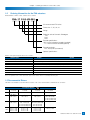
Ordering Information for the FHA actuators
Model number of FHA-C series actuators are as follows:
FHA- 17 C-50-US -250 AC servo actuator FHA series
Frame size: 17, 25, 32, 40
Design
Reduction ratio of Harmonic Drive® gear
50:1
100:1
160:1
Encoder specifications
US: 14 wire incremental encoder (standard)
E: 4 wire incremental encoder (optional)
Encoder resolution
250 : 2500 p/rev (incremental)
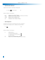
Optional specifications
Details of the optional specifications are as follows:
Optional spec.
AC100V power supply Brake for motor
Position sensors
Cable-end connectors
Cable outlet on back face
5 meter cables
24V
Details
Symbol
available for FHA-17C, -25C, -32C only
A
for holding motor shaft
B
origin and end limits
L
for motor cable (IP-20), for encoder cable (IP-40)
& for extension cable1C
from back bracket face
K
5m for each motor cable and encoder cable
F5
available for FHA-17C only
E
Note 1: For more details, refer to chapter 4.
Note 2: For requirement of two or more optional items, please contact Harmonic Drive LLC for availability and delivery date.
1-3 Recommended Drivers
The drives are available for use with FHA-C actuators. The correct actuator/drive combinations are as follows:
Incremental System
INC
VoltFHA-17C
FHA-25C
FHA-32C
FHA-40C
-xx-US250
-xx-US250
-zz-US250
-XX-US250
24V DDP-090-36–
–
–
DEP-090-36
–
–
–
AC200 RTL-230-18
RTL-230-18
RTL-230-18
RTL-230-36(1/50)
REL-230-18
REL-230-18
REL-230-18
REL-230-36(1/50)
–
–
–RTL-230-18(1/100,1/160)
–
–
–REL-230-18(1/100,1/160)
AC100 RTL-230-18
RTL-230-36(1/50)
RTL-230-36(1/50,1/100)
–
REL-230-18
REL-230-36(1/50) REL-230-36(1/50,1/100)
–
–
RTL-230-18(1/100,1/160)RTL-230-18(1/160)
–
–
REL-230-18(1/100,1/160)REL-230-18(1/160)
–
200V HA-655-2-200
HA-655-2-200
HA-655-4-200
HA-655-4-200
HA-675-2-200
HA-675-2-200
HA-675-4-200
HA-675-4-200
100V HA-655-2-100
HA-655-4-100
HA-655-4-100
–
HA-675-2-100
HA-675-4-100
HA-675-4-100
–
Harmonic Drive LLC 800-921-3332
4
Chapter 1 Overview of the FHA-C series
1-4 Specifications of FHA-C actuators
1-4-1 INCREMENTAL SYSTEM INC
Specifications of FHA-C series actuators with the 14 Wire Incremental Encoder are as follows:
ModelFHA-17C-xx-US250 FHA-25C-xx-US250FHA-32C-xx-US250FHA-40C-xx-US250
50
100
160
50
100
160
50
100
160
50
100
160
Maximum Torque
Note 2
N•m
39
57
64
150
230
260
281
398
453
500
690
820
Maximum Speed r/min96482790 45 28 80 4025703522
200V
N•m/A
21426722 45 72 27 54863164102
Torque Constant1)
100V
N•m/A
11213311 22 36 13 2743– – –
200V A 2.11.61.17.3 5.6 4.0 11.4 8.05.917.3
11.89.0
Maximum Current
Note 2
100V A 4.2 3.22.215 11 8.0 23 16 12 – – –
V/(rpm)
2.34.77.52.5 5.1 8.1 3.0 5.99.53.67.211.4
EMF Voltage Constant 200V
100V
V/(rpm)
1.22.43.81.3 2.6 4.1 1.5 3.04.8 – – –
(20ºC)7.9 2.6 1.00.73
Phase Resistance 200V
100V (20ºC)
2.0
0.65
0.25
–
200V
mH6.0
2.6
1.31.5
Phase Inductance
100V mH
1.5
0.65
0.33
–
2
2
(GD
/4)kg•m
0.170.67
1.70.81
3.2
8.3
1.8
7.1
18.14.9
19.5
50
Inertia of Actuator
(J) kgf•cm•s2 1.7 6.9 17 8.3 33 85 18 72 185 50 200510
Reduction Ratio 1:501:100
1:160
1:501:1001:1601:501:100
1:160
1:50
1:100
1:160
Allowable Radial Load
kN
2.9
4.9
9.5
14.7
Allowable Axial Load
kN
9.8
14.7
24.5
39.2
Allowable Torsional MomentN•m188 370 530690
Moment stiffness
N•m/rad
220x103 490x103790x1031400x103
One-way
arc-sec
60404040 30 30 40 3030403030
Positioning Accuracy
Motor encoder
2500 pulse/rev.
Quad encoder
-resolution; Note 3
Pulse/rev 500,000
1,000,000
1,600,000
500,0001,000,0001,600,000500,0001,000,000
1,600,000
500,000
1,000,000
1,600,000
Mass Kg2.5 4.0 6.512
Enclosure Totally enclosed, s elf-cooling (equivalent to IP44; Note 4)
Environmental conditions
Service / Storage temperature : 0~40ºC / -20 ~ 60ºC
Service / storage humidity
: 20~80%RH (no condensation)
Vibration / impact resistance : 24.5m/s2(freq:10-400Hz) , shock resistance 294 m/s2
No dust, no metal powder, no corrosive gas, no inflammable gas, no oil mist;
install in room, no direct sunlight
Altitude: less than 1,000 meters above sea level
Motor insulation
Insulation resistance: 100MΩ or more (by DC500V insulation tester)
Withstanding voltage: AC1500V / 1 minute
Insulation class: F
Orientation
All position
Note 1: The table shows output values of actuators.
Note 2: Values for saturated temperature under the conditions that the actuator is driven by an appropriate driver.
Note 3: Quad encoder resolutions are obtained by [motor encoder resolution] x 4 x [reduction ratio].
Note 4: All parts, except the rotary sliding parts (oil seal), of the actuators are protected against solid bodies of superior dimensions to 1mm,
and against the water sprays.
5
Chapter 1 Overview of the FHA-C series
1-5 External dimensions of FHA actuators
1-5-1 Incremental Systems INC
The external drawings are shown as follows:
66
• FHA-17C-xx-US250
INC
• FHA-25C-xx-US250
INC
Note 1: The parenthesized dimensions are applied for the actuators with a brake option.
Note 2: For detail dimensions, make sure of them referring our drawings for shipping.
Chapter 1 Overview of the FHA-C series
• FHA-32C-xx-US250
INC
• FHA-40C-xx-US250
INC
Note 1: The parenthesized dimensions are applied for the actuators with a brake option.
Note 2: For detail dimensions, make sure of them referring our drawings for shipping.
Unit: mm (third angle projection)
Harmonic Drive LLC 800-921-3332
7
Chapter 1 Overview of the FHA-C series
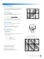
1-6
Mechanical accuracy of FHA actuators
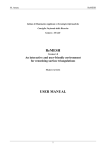
The machining accuracy of the output flange and the mounting flange are indicated in the table below.
Machined accuracy of the output flange
Machined parts
unit: mm
FHA-17C
FHA-25C
FHA-32C
FHA-40C
1. Axial run-out of output flange
0.010
0.012
0.012
0.014
2. Radial run-out of output flange
0.010
0.012
0.012
0.014
3. Parallelism between output flange and mounting flange
0.040
0.050
0.050
0.060
4. Concentricity between output flange to fitting face
0.040
0.050
0.050
0.060
Note: All values are T.I.R (Total Indicator Reading).
The measuring for the values are as follows:
• Axial run-out of output flange
The indicator (1) on a fixed portion measures the axial run-out
(T.I.R.) of perimeter of output flange for one revolution.
2
B
A
• Radial run-out of output flange
1
4 A
The indicator (2) on a fixed portion measures the radial run-out
(T.I.R.) of perimeter of output flange for one revolution.
3 B
3 B
4 A
• Parallelism between output flange and mounting flange
The indicator (3) on the output flange measures the axial run-out
(T.I.R.) of each perimeter of both sides of the fixing flange
for one revolution.
• Concentricity between output flange to fitting face
The indicator (4) on the output flange measures the radial run-out
(T.I.R.) of each surface of both fitting face (drive-end side
and opposite side) for one revolution.
(4)
(4)
8
(3)
(3)
(1)
(2)
Chapter 1 Overview of the FHA-C series
1-7
One-way positioning accuracy
Position difference
Commanded stopping position
The one-way positioning accuracy means the maximum
positional difference between a commanded theoretical
position and its actual angular position for serial positioning
in one revolution when approached from the same
direction.(refer to JIS B-6201-1987)
The one-way positioning accuracy of FHA-C actuators
is almost equal to the angular positioning accuracy of the
Harmonic Drive® gear, because the effect on the
positioning error of the built-in motor is reducted to its
1/50 or 1/100 or1/160 by the gearing.
Actual stopping
position
The one-way positioning accuracy is shown in the table below:
Start position
Model FHA-17C FHA-25C FHA-32C FHA-40C
Item
50:1 100:1 160:1
50:1 100:1 160:1
50:1 100:1 160:1 50:1 100:1 160:1
One-way arc second
604040 403030 403030 403030
positioning accuracy
1-8 Encoder resolution
The motors of FHA-C actuators are equipped with an incremental encoder of 2500 resolutions. Because the motor rotation is reduced
to 1/50 or 1/100 or 1/160 by the gear component, the resolution of the output flange is 50 or 100 or 160 times the encoder revolution.
Additionally, the incremental encoder signal is used in signal is used in quadrature.
The following high resolutions are obtained:
Encoder
Incremental
Encoder resolution2,500 (10,000: quadruplicated)
Reduction Ratio
50:1
100:1
160:1
Resolution of output flange
Pulse/rev 500,000 1,000,0001,600,000
Resolvable angle per pulse
arc sec
2.6
1.3
All values are approximate.)
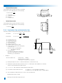
1-9 Torsional Stiffness of Actuators
1-9-1 Moment stiffness
Load Deflection The moment stiffness refers to the stiffness when a moment load is
applied to the output flange of the actuator (shown in the figure).
For example, when a load is applied to the end of an arm attached on
the output flange of the actuator, the face of the output flange of the
actuator tilts in proportion to the moment load. The moment stiffness
is expressed as the load/deflection angle.
DO NOT APPLY TORQUE, LOAD OR THRUST TO THE HOLLOW SHAFT DIRECTLY.
The sleeve (hollow shaft) is bonded to the output rotary shaft. Accordingly, the adhered sleeve may
be detached from the output rotary shaft if a torque or load is applied to the sleeve (hollow shaft).
Do not apply any torque, moment load or thurst load directly to the sleeve (hollow shaft).
Item
Model
FHA-17C
FHA-25C
FHA-32C
FHA-40C
N•m/rad
220 x 103
490 x 103
790 x 103
1400 x 103
Moment Stiffness
Kgf•m/rad
22 x 10 50 x 10 80 x 10 140 x 103
Kgf•m/arc-min6.5
3
3
15
3
23
42
Harmonic Drive LLC 800-921-3332
9
Chapter 1 Overview of the FHA-C series
1-9-2 Torsional Stiffness
When a torque is applied to the output flange of the actuator with the motor locked,
the resulting torsional wind up is near proportional to the torque.
A
Torsion
Hysteresis
Loss
The upper right figure shows the torsional stiffness characteristics of the output flange
applying torque starting from zero to plus side [+T0] and minus side [–T0].
This trajectory is called torque-torsion characteristics which typically follows
a loop 0→A→B→A’→B’→A as illustrated. The torsional stiffness of the
FHA-C actuator is expressed by the slope of the curve that is a spring rate
(wind-up) (N•m/rad).
-T0
B
O1
O
A1
The torsional stiffness may be evaluated by dividing torque-torsion characteristics
curve into three major regions. The spring rate of each region is expressed
K1, K2, and K3 respectively.
K1: spring rate for torque region 0-T1
K2: spring rate for torque region T1-T2
K3: spring rate for torque region over T2
Torsion
The wind-up for each region is expressed as follows:
• Wind-up for torque region 0-T1:
+T0
Torque
ϕ=
K3
T
K1
02
T - T1
K2
• Wind-up for torque region T1-T2:
ϕ = θ1 +
• Wind-up for torque region over T2:
T - T2
ϕ = θ2 +
K3
K2
01
K1
O
T1
T2
Torque
Ø ϕ : Wind-up
The table below shows T1-T3, K1-K3, and θ1-θ2 values of each actuator.
Model
FHA-17C
FHA-25C
FHA-32C FHA-40C
Reduction Ratio
50:1 100:1160:1
50:1 100:1160:1
50:1100:1 160:1
50:1100:1 160:1
T1N•m
7.0 7.0 7.0
29 29 29
54 54 54
108108 108
kgf•m
0.7 0.7 0.7
3.0 3.0 3.0
5.55.5 5.5
11 11 11
K1x10 4 N•m/rad 1.1 1.3 1.3
4.7 6.16.1
8.811 11
17 21 21
kgf•m/arc min 0.32 0.4 0.4
1.4 1.8 1.8
2.83.2 3.2
5.06.3 6.3
θ1x10 -4 rad
6.4 5.1 5.1
6.2 4.8 4.8
6.14.9 4.9
6.45.1 5.1
arc min
2.2 1.8 1.8
2.1 1.7 1.7
2.11.7 1.7
2.21.8 1.8
T2N•m
25 25 25
108 108 108
196196 196
382382 382
kgf•m
2.5 2.52.5
11 11 11
2020 20
3939 39
K2K2x10 4 N•m/rad
1.3 1.71.7 6.1 7.77.7
1114 14
2129 29
kgf•m/arc min 0.4 0.5 0.5
1.8 2.3 2.3
3.44.2 4.2
6.38.5 8.5
θ2x10 -4 rad
19.5 15.6 15.6
19.2 15 15
19.115.1 15.1
19.314.7 14.7
arc min
6.7 5.4 5.4
6.6 5.1 5.1
6.45.2 5.2
6.65.0 5.0
K3x10 4 N•m/rad 2.0 2.52.5 8.4 11 11
1520 20
3037 37
kgf•m/arc min
0.6
0.75 0.75
2.5
3.3
3.3
4.5
5.8
5.8
9
11
11
The table below shows torque-wind-up relation for reference.
Model FHA-17C
FHA-25C FHA-32C
Reduction Ratio
2 arc-min
4 arc-min
6 arc-min
10
50:1
6.3
14
22
100:1 160:1
8.1
8.1
18
18
29
29
50:1
27
62
97
100:1
37
82
136
160:1
37
82
136
50:1
51
117
179
100:1 160:1
63
63
148
148
243
243
50:1
98
220
340
(unit:N•m)
FHA-40C
100:1 160:1
129
129
300
300
490
490
Chapter 1 Overview of the FHA-C series
1-10 Rotary direction
Forward rotary direction is defined as clockwise (CW)
rotation viewing the output flange of the actuator when
the HA800 signals forward commands.
The direction can be reversed by the setting of
[parameter mode]→[8: rotary direction] of the driver.
Value
FWD command
0
1
REV command
Setting
FWD rotation
REV rotation
Default
REV rotation
FWD rotation
1-11 Impact resistance
The actuators are resistant to impacts along the radial axes.
Impact acceleration: 294 m/s2
However, do not apply impact to the output flange.
1-12 Vibration resistance
The allowable vibration from all directions is as follows:
Vibration acceleration: 24.5 m/s2
(Frequency:10~400Hz)
1-13 Torque-speed characteristics
The following are actuator speed-torque characteristics in combination
with a proper the HA800 drive showing allowable
duty range. Refer to chapter 2 [selection guidelines] for using
the FHA-C series actuators most suitably.
• Continuous duty range
The range allows continuous operation for the actuator.
• 50% duty range
The range allows the 50% duty time operation of a cycle time.
Refer section 2-4-5 [duty cycle].
• Acceleration and deceleration range
The range allows instantaneous operation like acceleration and deceleration, usually.
The continuous and 50% ranges in each graph are measured on the condition of the
FHA-C actuator attached on the heat radiation plate described in the figure.
Harmonic Drive LLC 800-921-3332
11
Chapter 1 Overview of the FHA-C series
Acc./dec. range
50% duty range
Radiation plate 350x350x18(mm)
Acc./dec. range
Torque [Nm]
Torque [Nm]
Radiation plate 300x300x15(mm)
50% duty range
Continuous range
Continuous range
Speed [r/min]
Speed [r/min]
Radiation plate 300x300x15(mm)
Radiation plate 350x350x18(mm)
Acc./dec. range
50% duty range
Torque [Nm]
Torque [Nm]
Acc./dec. range
Continuous range
50% duty range
Continuous range
Speed [r/min]
Speed [r/min]
Acc./dec. range
50% duty range
Continuous range
Speed [r/min]
12
Radiation plate 350x350x18(mm)
Acc./dec. range
Torque [Nm]
Torque [Nm]
Radiation plate 300x300x15(mm)
50% duty range
Continuous range
Speed [r/min]
Chapter 1 Overview of the FHA-C series
Radiation plate 400x400x20(mm)
Radiation plate 500x500x25(mm)
Acc./dec. range
Torque [Nm]
Torque [Nm]
Acc./dec. range
50% duty range
50% duty range
Continuous range
Continuous range
Speed [r/min]
Speed [r/min]
Radiation plate 500x500x25(mm)
50% duty range
Torque [Nm]
Torque [Nm]
Acc./dec. range
50% duty range
Continuous range
Continuous range
Speed [r/min]
Speed [r/min]
Radiation plate 400x400x20(mm)
Radiation plate 500x500x25(mm)
Acc./dec. range
Torque [Nm]
Torque [Nm]
Acc./dec. range
50% duty range
50% duty range
Continuous range
Speed [r/min]
Speed [r/min]
Harmonic Drive LLC 800-921-3332
13
Chapter 1 Overview of the FHA-C series
1-14 Cable specifications
The following tables show the lead specifications for the motors and the encoders of the FHA-C actuators.
• Motor Cable
Color
Red
White
Black
Green/yellow
Blue
Yellow
(Shield)
Standard
Motor phase-U
Motor phase-V
Motor phase-W
PE
No connection
No connection
FG
• Encoder Cable for 14 Wire Incremental Encoder INC
Color
Red
Green
Gray
Yellow
Brown
Blue
Orange
Signal
Vcc
A
B
Z
U
V
W
Output circuit
Brake option
Motor phase-U
Motor phase-V
Motor phase-W
PE
Brake
Brake
FG
Color
Black
Green/White
Gray/White
Yellow/White
Brown/White
Blue/White
Orange/White
Signal
GND
A
B
Z
U
V
W
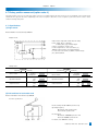
Input circuit of user’s device (Ex.)
VCC
A,B,Z,U,V,W
AM26LS31C (Equivalent)
_ _ _ _ _ _
A, B,Z,U, V, W
R1
AM26LS32C (Equivalent)
GND
R1:120_
VCC
C1
C2
FG
FG
GND
Voltage strength of capacitor C1,C2 : 50V
• Encoder Cable for 4 Wire Incremental Encoder INC
Color
Red
Black Yellow
Blue
(Shield)
1144
Signal
+5V
0V
SD
SD
FG
Reference
Power
Supply
Serial Signal
Differential Output
Chapter 1 Overview of the FHA-C series
1-15 Signal Waveform
Signal waveform specifications of new version FHA-17C / 25C / 32C / 40C for US market
Figure 1 shows A, B and Z signal and relationship with U signal with CW rotation
facing the encoder end (the end of the actuator output shaft.)
Figure 1
a, b, c, d = 1/4T ± 1/10T
(a + b), (b+c) = 1/2T ± 1/8T
Tz = 1/2T ~ 3/2T
(The Z phase includes a HIGH state
in case of both of A and B phase is
HIGH state.)
T = 360º / 2500
a < ± 10º / 6 (Mechanical angle)
Figure 2 shows U, V, and W signal and relationship[ with motor’s EMF with CW rotation
facing the encoder end (the end of the actuator output shaft.)
Figure 2
U-W(G)
Voltage of U-W (G) means of voltage
of U terminal grounding W terminal.
R = 60º ± 3º
Hn = 10º ± 3º (Mechanical angle)
d < ± 10º / 6 (Mechanical angle)
Encoder Output
Harmonic Drive LLC 800-921-3332
15
Chapter 2 Guidelines for sizing
Inertia
(kg•m 2 ) (kgf•cm•s 2 )
Chapter 2 Selection guidelines
1000 10000
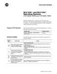
2-1 Allowable load inertia
100
Refer to appendix 1 for the calculation of moment inertia.
When selecting the actuator make certain that the load
inertia and the maximum speed are less than the allowable
values that are indicated in the table below.
Actuator model
FHA-40C-160
FHA-40C-100
FHA-32C-160
To achieve high accuracy performance, select an
FHA actuator wherein the allowable moment of inertia
(reference value) is greater than the load inertia.
1000
10
100
FHA-25C-160
1
10
FHA-17C-160
0.1
1
FHA-40C-50
FHA-25C-100
FHA-32C-50
FHA-25C-50
FHA-17C-100
FHA-17C-50
0
FHA-17C
FHA-32C-100
20
FHA-25C
40
60
80
Max. speed (r/min)
FHA-32C
100
120
FHA-40C
Reduction ratio
50:1 100:1 160:1 50:1 100:1 160:1 50:1 100:1 160:1 50:1 100:1 160:1
Maximum speed
(r/min)
96
48
30
90
45
28
80
40
25
70
35
22
Moment of inertia
kg•m2
0.17 0.67 1.7 0.81 3.2 8.3 1.8 7.118.14.9 19.5 50
of actuator kgf•cm•s2 1.7 6.9 17 8.3 33 85 18 7218550 200510
Allowable moment
kg•m2 0.542.15.1 2.4 10 25 5.4 215415 60150
of inertia
kgf•cm•s2 5.4 21 52 24 100 260 55 210550150 6101500
2-2 Variable load inertia
FHA-C series actuators include Harmonic Drive® gear that has a high
reduction ratio. Because of this there are minimal effects of variable
load inertias to the servo drive system. In comparison to direct servo
systems this benefit will drive the load with a better servo response.
For example, assume that the load inertia increases to N-times during
its motion (for example, robot arms). The effect of the variable load
inertia to the [total inertia converted into motor shaft] is as follows:
The symbols in the formulas are:
JS: Total inertia converted into motor shaft
JM: Moment inertia of motor
R: Reduction ratio of FHA actuator
L: Ratio of load inertia to motor inertia
N: Variation ratio of load inertia
•
Direct drive
Before: JS = Jm ( 1 + L )
After: Js’ = Jm ( 1+ NL )
Ratio:
•
FHA actuator drive
Before:
Js = Jm
L
( 1+ R2 )
After:
Js’ = Jm
NL
Js’/Js = 1 + NL
1+L
( 1 + R2 ) 1 + NL / R2
Ratio:
Js’/Js =
1 + L / R2
In the case of the FHA actuator drive, as the reduction ratio is [R=50], [R=100] or [R160] and the square of the reduction ratio
[R2=2500], [R2=10000] or [R2=25600] the denominator and the numerator of the ratio are almost [1]. Then the ratio is [F=1].
This means that FHA drive systems are hardly effected by the load inertia variation. Therefore, it is not necessary
to take the load inertia variation into consideration for selecting an FHA actuator or for setting up the driver.
16
Chapter 2 Guidelines for sizing
2-3 Verifying loads
The FHA-C actuators comprise a precise cross roller bearing for directly supporting the load weight. To give full ability of the actuator,
verify that the maximum load weight is less than the allowable load and life and static safety coefficient of the cross roller bearing.
•
Verifying procedures:
(1) Verifying the maximum load
Calculate the maximum load (Mmax, Frmax, Famax).
↓
Verify the maximum loads (Mmax, Frmax, Famax) are less than (<) allowable loads (Mc, Fr, Fa)
(2) Verifying the life of the cross roller bearing
Calculate the average radial load (Frav) and the average axial load (Faav).
↓
Calculate the radial load coefficient (X) and the axial load coefficient (Y).
↓
Calculate the life of the bearing and verify the life is allowable.
(3) Verifying the static safety coefficient
Calculate the static equivalent radial load (Po)
↓
Verify the static safety coefficient.
•
Specifications of the cross roller bearing
The following table shows the specifications of the cross roller bearings built in FHA-C actuators.
Table 1: Specifications of the cross roller bearings
Model
Circular Offset(R)
pitch of roller
(dp)
(R)
Basic dynamic
load rating
(C)
Basic static
load rating
(Co)
N
Allowable
axial load
(Fa)
N
Allowable
torsional moment
(Mc)
mmmm
FHA-17C
77
17
10800
18700
2940
9800
188
FHA-25C
96.2
18.0
18000
33300
4900
14700
370
FHA-32C
112.2
18.5
24100
44300
9500
24500
530
FHA-40C
148.8
26.5
44900
88900
14700
39200
690
•
N
Allowable
radial load
(Fr)
N
N•m
Actuator
Calculating the maximum load
Load
Calculate the maximum load (Mmax, Frmax, Famax) with the following
formula and verify that they are less than their allowances.
Fr
dp
Mmax=Frmax(Lr+R)+Famax:La(1)
La
Where, the variables of the formula are:
Mmax: Maximum torsional moment in N•m(kgf•m)
Frmax: Maximum radial load in N(kgf); See Fig.1.
Famax: Maximum axial load in N(kgf); See Fig.1.
Lr, La: Loading point in mm; See Fig.1.
R: Fa
Lr
R
Offset: See Fig.1 and Table 1.
Figure 1 Loads
Harmonic Drive LLC 800-921-3332
17
Chapter 2 Guidelines for sizing
•Calculating average loads: average radial
and axial loads, average output speed
•
Average radial load: Frav
10/3
n1 t1 Fr1 10/3+n2t2 Fr2 10/3...nntn Frn10/3
Frav=
(2)
n1t1 + n2t2 + ... +nn tn
√
| |
| |
|
Fr1
Fa 1
Average axial load: Faav
10/3
n1 t1 Fa1 10/3+n2t2 Fa2 10/3...nntn Fan
Faav=
n1t1 + n2t2 + ... +nn tn
√
| |
| |
| |
10/3
(3)
Fa 2
– Axial load +
•
Time
Fr3
Note: "Fr1" is the maximum radial load in "t1" range,
and "Fr3" is the maximum radial load in "t3" range.
Fr2
– Axial load +
When the radial and/or axial loads vary during motion, calculate and verify
the life of the cross roller bearing converting the loads to their average values.
Time
Fa 3
t1
Note: "Fa1" is the maximum radial load in "t1" range,
and "Fa3" is the maximum radial load in "t3" range.
•
Nav=
n1 t1+n2t2+...nntn(4)
t1 + t2 + ... + tn
n1
• Calculating radial load factor and axial load factor
Both load factors are different with average loads as follows:
• When the right formula is satisfied,
Faav
<1.5(5)
Frav + 2(Frav ( L r+ R ) + Faav.La ) /dp
X=1.0, and Y=0.45
• When the formula below is satisfied,
Faav
>1.5(5’)
Frav + 2(Frav ( Lr + R ) + Faav.La ) /dp
X=0.67, and Y=0.67
Where, the variables of the formula are:
Mmax: Frmax: Famax: Lr, La: Maximum torsional moment in N•m(kgf•m); obtained by the formula (1)
Maximum radial load in N(kgf); See Fig.1.
Maximum axial load in N(kgf); See Fig.1.
Loading point in mm; See Fig.1.
R: Offset; See Fig.1 and Table 1.
dp: Circular pitch of roller: See Fig.1 and Table 1.
18
t3
n2
Average output speed: Nav
– Axial load +
t2
n3
Time
Chapter 2 Guidelines for sizing
•
Equivalent dynamic radial load
The equivalent dynamic radial load is:
(
2 (Frav (Lr + R) + Faav . La)
PC = X . Frav +
dp
)
+ Y.Faav
(6)
Where, the variables of the formula are:
Frav: Faav: dp: X:
Y:
Lr, La: R: •
Average radial load in N(kgf); obtained by formula (2).
Average axial load in N(kgf); obtained by formula (3).
Circular pitch of roller: See Fig.1 and Table 1.
Radial load factor; obtained by formula (5)
Axial load factor; obtained by formula (5')
Loading point in mm; See Fig.1.
Offset; See Fig.1 and Table 1.
Life of cross roller bearing
Calculate the life of cross roller bearing with the formula below:
L B-10 =
( )
10/3
106
C
x
fw.Pc
60 x Nav
(7)
Where, the variables of the formula are:
LB-10: Life of cross roller bearing in hour
Nav: Average output speed in r/min; obtained by formula (4).
C: Basic dynamic load rating in N (kgf). See Table 1.
Pc: Average dynamic radial load in N (kgf); obtained by formula (6) below.
fw: Load factor:
For smooth operation without shock or vibration:
For normal operation:
For operation with shock and/or vibration:
•
fw=1 to 1.2
fw=1.2 to 1.5
fw=1.5 to 3
Life of cross roller bearing for swaying motion
Calculate the life of cross roller bearing with the formula below:
106
L OC =
x
60 x n1
90
θ
( )
x C
fw.Pc
10/3
(8)
Where, the variables of the formula are:
Loc: Life of cross roller bearing in hour
n1:
Average output speed in r/min; obtained by formula (4).
C: Basic dynamic load rating in N (kgf). See Table 1.
Pc: Equivalent dynamic radial load in N (kgf); obtained by formula (6).
fw: Load factor:
For smooth operation without shock or vibration: fw=1 to 1.2
For normal operation:
fw=1.2 to 1.5
For operation with shock and/or vibration:
fw=1.5 to 3
θ: Half of sway angle; See the right figure.
Sway Motion
When the sway angle is less than 5 degrees, consult Harmonic Drive Systems.
Harmonic Drive LLC 800-921-3332
19
Chapter 2 Guidelines for sizing
•
Equivalent static radial load
Equivalent static radial load is obtained by formula (9) below.
2Mmax
PO = Frmax +
+ 0.44 Famax
dp
(9)
Where, the variables of the formula are:
Po:
Mmax: Frmax: Famax: dp: •
Equivalent static radial load in N (kgf)
Maximum torsional moment in N•m(kgf•m); obtained by the formula (1)
Maximum radial load in N(kgf); See Fig.1.
Maximum axial load in N(kgf); See Fig.1.
Circular pitch of roller: See Fig.1 and Table 1.
Static safety factor
Generally, the static safety factor is limited by the basic static load rating (Co).
However, for the heavy duty, the factor is limited by the following formula:
Co
fs = Po
(10)
Where, the variables of the formula are:
fs: Co:
Po:
20
Static safety factor;
For precise positioning operation:
fs > 3
For operation with shock and/or vibration:fs > 2
For normal operation:
fs > 1.5
Basic static load rating in N (kgf). See Table 1.
Equivalent static radial load in N (kgf); obtained by formula (9).
2-4 Duty cycles
Screw pitch (mm)
When a duty cycle includes many frequent start and stop operations,
the actuator generates heat by high starting and braking current.
Therefore, it is necessary to study the duty cycle profile.
Speed (r/min)
30
The study is as follows:
10
2-4-1 Actuator speed
20r/min
Calculate the required actuator speed (r/min) to drive the load.
For linear motion, convert with the formula below:
Linear speed (mm/min)
Rotary speed (r/min) = Pitch of screw (mm)
35r/min
3
50r/min
70r/min
100r/min
(9)
1
Select a reduction ratio from [50], [100] and [160] of an actuator
of which the maximum speed is more than the required speed.
30
100
300
1000
3000
Li near speed ( mm/min)
2-4-2 Load inertia
Calculate the load inertia driven by the FHA-C series actuator.
Refer to appendix 1 for the calculation.
Mass: W
Tentatively select an FHA-C actuator referring to section
[2-1 allowable load inertia] with the calculated value.
Radius:r
2-4-3 Load torque
Calculate the load torque as follows:
•
Friction:
Rotary motion
The torque for the rotating mass [W] on the friction ring of radius [r]
as shown in the figure to the right.
T = 9.8 x µ x W x r
T: µ : W: r: torque (N•m)
coefficient of friction
mass (kg)
radius of friction face (m)
Ex. torque calculation (friction=0.1)
FHA :(ratio: 1/50) 20% torque of maximum torque
50 N •m
20 N • m
10 N • m
300
100 N • m
200 N • m
300 N • m
30 N • m
7 N• m
5 N• m
3 N• m
100
2 N• m
In the right graph, the oblique solid lines
for torque have been calculated with the
coefficient of the friction of µ =0.1.
The oblique dot-chain lines show
20% torque of actuators converted from
300% torque corresponding to its maximum torque.
FHA- 40C-50
FHA-32C-50
1 N• m
30
FHA-25C-50
FHA- 17C-50
10
30
100
300
1000
3000
Mass: W (k g)
Harmonic Drive LLC 800-921-3332
21
• Horizontal linear motion
The following formula calculates the torque for horizontal
linear motion of mass [W] fed by the screw of pitch [P].
T = 9.8 x µ x W x P
2xπ
T :torque (N•m)
µ :coefficient of friction
W :mass (kg)
P :screw pitch (m)
Mass: W
Pitch: P
Friction:
• Vertical linear motion
The following formula calculates the torque for vertical
linear motion of mass [W] fed by the screw of pitch [P].
T = 9.8 x W x P
2xπ
Mass: W
2-4-4Acceleration time and deceleration time
Calculate acceleration and deceleration times for the selected actuator.
Acceleration:
Deceleration:
td = (Ja + Jl) x 2 x π x
60
N
Tm + 2 x Tf – Tl
Speed
Ta:acceleration time (sec)
Td:deceleration time (sec)
Ja:actuator inertia (kg•m2)
JL:load inertia (kg•m2)
N:actuator speed (r/min)
TM:maximum torque of actuator (N•m)
TF:actuator friction torque at max. speed (N•m)
TF = KT x IM - TM
where, KT: torque constant (N•m/A)
IM: maximum current (A)
TL:load torque (N•m)
note that the polarity of the load torque is
plus (+) for counter direction of revolution,
and minus (-) for same direction.
•
Pitch: P
N
ta = (Ja + Jl) x 2 x π x
60
Tm – Tl
N
ta
Example 1
The load conditions are:
Rotary speed:
60r/min
Moment of inertia: 1.5 kg•m2
Load torque is so small as to be neglected.
(1)Referring the figure in section 2-1, FHA-25C-50 actuator is selected for the load.
(2)Referring the specification table provided in section 1-4, JA=0.81 kg•m2, TM =150 N•m, KT=22 N•m/A,
and IM =7.3A are obtained for the FHA-25C-50.
(3)TF = 22 x 7.3 – 150 = 10.6 N•m is obtained with the formula above.
(4)Acceleration and deceleration times are:
ta = (0.81+1.5 ) x 2 x π / 60 x 60 / 150 = 0.097 s
td = (0.81+1.5) x 2 x π / 60 x 60 / (150 + 2 x 10.6) = 0.085 s
(5)If the calculated acceleration times are too long, correct the situation by:
•Reducing load moment of inertia
22
22
•Selecting an actuator with a larger frame size
td
Time
Chapter 2 Guidelines for sizing
2-4-5 Calculating equivalent duty
The load conditions, which is torque, speed, moment of inertia,
acceleration/deceleration time, loading time, are limited by the
actuator to drive the load. To select the proper actuator, the
equivalent duty of the load should be calculated.
Speed
N
Time
ta
The %ED (percent equivalent duty) is:
tr
td
ts
t: duty cycle
where, ta:
td:
tr:
t:
Kla:
Klr:
Kld:
acceleration time in second
deceleration time in second
driving time in second
single cycle time in second
duty factor for acceleration time
duty factor for driving time
duty factor for deceleration time
Torque
Kla x ta + Klr x tr + Kld x td
%ED =
x 100
t
Ta
Tr
Ta
Time
• Example 2: getting duty factors of Kla, Klr and Kld
With an example of the duty factor graph for FHA-25C-50 actuator,
the way of getting the duty factors of Kla, Klr and Kld is described
as follows:
The load conditions are the same as the example described in
example 1: the inertia load is accelerated by the maximum
torque,
and is driven with a constant speed, and decelerated by the
maximum torque. The displacement angle is 120 degrees and
the cycle time is 2.0 s.
KLr
(1)Kla, and Kld: the speed is desired at 30 r/min as
the average of 0 and 60 r/min.
Then, Kla = Kld = 7.0 from the graph.
(2)Klr (ex.: Klr =1.0) from the graph pointing the load torque
Tr (ex. Tr= 0) and driving speed (ex: Nr=60r/min).
(3) The driving time is calculated as the area of the
trapezoid of speed-time graph. Then the
displacement angle is:
θ = (N / 60) x {tr + (ta + td) / 2} x 360
Then, tr = θ / (6 x N) – (ta +td) /2
As the 120 deg. is equal to 0.33rev (=120/360), the driving angle at the speed of 60r/min (=1r/s) is:
tr = (0.333-0.091)/1 = 0.242 s
(4) Because the cycle time is 2.0s, the %ED is obtained as follows:
%ED = (7 x 0.097+1 x 0.242 + 7 x 0.085) / 2 x 100 = 76%
It is possible to drive the actuator with the load specifications continuously,
because the %ED is less than 100%.
If the %ED is excesses 100%, correct the situation by:
• Changing the speed-time profile
• Reducing load moment of inertia
• Selecting an actuator with a larger frame size
Harmonic Drive LLC 800-921-3332
23
Chapter 2 Guidelines for sizing
• Graphs of duty factor
Allowed range
Torque [Nm]
Torque [Nm]
Allowed range
Speed [r/min]
Speed [r/min]
Allowed range
Torque [Nm]
Torque [Nm]
Allowed range
Speed [r/min]
Speed [r/min]
Allowed range
Torque [Nm]
Torque [Nm]
Allowed range
24
Speed [r/min]
Speed [r/min]
Chapter 2 Guidelines for sizing
Allowed range
Torque [Nm]
Torque [Nm]
Allowed range
Speed [r/min]
Speed [r/min]
Allowed range
Torque [Nm]
Torque [Nm]
Allowed range
Speed [r/min]
Speed [r/min]
Allowed range
Torque [Nm]
Torque [Nm]
Allowed range
Speed [r/min]
Speed [r/min]
Harmonic Drive LLC 800-921-3332
25
Chapter 2 Guidelines for sizing
2-4-6 Effective torque and average speed
Additionally to the former studies, the effective torque and the average speed should be studied.
(1) The effective torque should be less than allowable continuous torque specified by the driver.
(2) The average speed should be less than allowable continuous speed of the actuator.
Calculate the effective torque and the average speed of an operating cycle as shown in the former figure.
Tm:
effective torque (N•m)
Ta:
maximum torque (N•m )
Ta2 x (ta + td) + Tr2 x tn
Tm =
Tr:
load torque (N•m)
tta: acceleration time (s)
td: deceleration time (s)
tr: running time at constant speed (s)
N / 2 x ta + N x tr + N / 2 x td
Nav =
t: time for one duty cycle (s)
tNav:
average speed (rpm)
N:
driving speed (rpm)
√
If the result is greater than the value in the table below, calculate once again after reducing the duty cycle.
Model FHA-17C
FHA-25C
FHA-32C
FHA-40C
Items
5010016050 10016050100
16050100
160
Reduction Ratio
1:50 1:100 1:160 1:50
1:100 1:160 :50
1:100 1:160 :50 1:100 1:160
Continuous torque
N•m
15
24
24
35
75
85
60
130 200
85
190 300
Continuous speedrpm
70 35 22 70 35 22 60 301950 2516
• Example 3: getting effective torque and average speed
The parameters are the same as the example 1 and 2 for an FHA-25C-50.
(1) Effective torque
From the parameters of Ta =Td =150 N•m,Tr =0 N•m, ta=0.097 s, tr=0.243 s, td=0.085 s, t=2 s,
√
1502 x (0.097+0.085)
Tm =
= 45 N•m
2.0
As the value of Tm (45N•m) exceeds its allowable continuous torque (35N•m), it is impossible to drive the actuator
continuously on the duty cycle. The following equation is introduced by converting the equation for effective torque.
The limited time for one duty cycle can be obtained by substituting the continuous torque for the Tm of the
following equation.
T=
Ta2 x (ta + td) + Tr2 x Tr
Tm2
Substituting 150 N•m for Ta, 150 N•m for Td, 0 N•m for Tr, 35 N•m Tm, 0.097 s for ta,
0.243 s for tr, and 0.085 s for td:
T=
1502 x (0.097+0.085)
= 3.34
352
Namely, when the time for one duty cycle is set more than 3.4s, the effective torque [Tm] becomes less
than 34.0 N•m, and the actuator can drive the load with lower torque than the continuous torque continuously.
(2) Average speed
From the parameters of N =60 r/min, ta=0.097 s, tr=0.243 s, td=0.085 s, t=3.5 s,
60/2 x 0.097+60 x 0.242+60/2 x 0.085)
Nav =
= 5.88 r/min
3.4
As the speed is less than the continuous speed of the FHA-25C-50,
it is possible to drive it continuously on new duty cycle.
26
Chapter 2 Guidelines for sizing
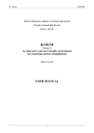
2-4-7 Permissible overloaded time
The overloaded time is limited by the protective function in the driver even if the duty cycle is allowed.
The limits are shown in the figure below.
1000
Overloaded times [s]
FHA-17C-160
FHA-32C-160
FHA-25C-160
FHA-32C-100
FHA-25C-100
FHA-40C-160
100
FHA-17C-50
FHA-17C-100
FHA-40C-100
FHA-25C-50
FHA-32C-50
10
FHA-40C-50
1
10
100
1000
Torque [Nm]
2-4-8 Regeneration energy
When a large inertia is accelerated and decelerated frequently, the regenerated energy will be quite large. The HA-650 driver is equipped with a
regeneration resistor of 40W capacity to consume the energy. If the energy is larger than the capacity, an additional resistor is required externally.
The required capacity of the external resistor is:
Wr =
1
2
( ){
JA + JL x
2 xπ x N
60
}
2
x
1
t
– 40 (W)
Wr: capacity of external resistor (W)
JA: actuator inertia (kg•m2)
JL: load inertia (kg•m2)
N: actuator speed at deceleration (r/min)
T: time for one duty cycle (s)
Additional resistors are not required for FHA-17C and FHA-25C actuators. However, it is sometimes required for FHA-32C and FHA-40C actuators.
For reference, the graph to the right shows the required capacity of the resistor, when load inertia is three times of actuator inertia.
External resistor for FHA -32C (JL=3JA)
Speed (r/min)
80
Speed (r/min)
100W
200W
100W
80
50W
200W
50W
70
70
60
Unnecessary
60
Unnecessary
50
50
40
External resistor for FHA -40C (JL=3JA)
40
2
4
Time for one duty cycle (s)
6
2
4
6
8
10
Time for one duty cycle (s)
Harmonic Drive LLC 800-921-3332
27
Chapter 3 Installing the FHA actuator
Chapter 3 Installing the FHA-C actuator
3-1 Receiving Inspection
Check the following when products are received.
•
Inspection procedure
(1) Check the shipping container and item for any damage which may have been caused during transportation.
If the item is damaged, immediately report the damage to the dealer it was purchased from.
(2) A label is attached on the right side of the FHA actuator. Confirm the products you ordered by comparing with
the model on the [TYPE] line of the label. If it is different, immediately contact the dealer it was purchased from.
The model code is interpreted as follows:
FHA- 17 C-50-US -250 AC servo actuator FHA series
Frame size: 17, 25, 32, 40
Design version
Reduction ratio of Harmonic Drive® gear
Encoder specifications
Encoder resolution
Option
Refer the section 1-2 in this manual for the detail of the model codes.
(3) On the label of the driver, the model code of the FHA-C series actuator to be driven is indicated on the
[ADJUSTED FOR USE WITH] line. Match the actuator with its driver so as not to confuse the item with the other actuators,.
!
CAUTION
Only connect the actuator specified on the driver label.
The drivers have been tuned for the actuator specified on the driver label.
Wrong combination of drivers and FHA actuators may cause low torque
problems or over current that may cause physical injury and fire.
(4) A model of the driver is marked on the [TYPE] line of the label.
The last three digits indicate the voltage of power supply.
200: 3-phase or single phase 200V
100: single phase 100V
If the voltage to be supplied is different from the label voltage,
immediately contact the dealer it was purchased from.
!
CAUTION
28
Do not connect a supply voltage other than the voltage specified on the label.
The wrong power supply voltage may damage the driver resulting in physical injury and fire.
Chapter 3 Installing the FHA actuator
3-2
Notice on handling
Handle FHA-C series actuators with care, specifically:
(1) Do not apply impact or unnecessary excessive force to output flange of actuators.
(2) Do not put actuators on or in a location where the driver could easily fall.
(3) Do not plug the actuators directly into a commercial line power source.
This could burn out the actuator, potentially resulting in a fire and/or electrical hazard.
!
(4) The allowable temperature for storage is from –20ºC to +60ºC.
Do not expose it to direct sunlight for a long time and do not store
it in areas with widely fluctuating temperatures.
CAUTION
(5) The allowable relative humidity for storage is less than 80%.
Do not storage it in a highly humid place or in a place where temperature
changes excessively during the course of a day.
3-3
(6) Do not store units in locations with corrosive gas or particles.
Location and installation
3-3-1 Environment of location
The environmental conditions of the location must be as follows.
• Service temperature: 0ºC ~ 40ºC
When the actuator is installed in a closed space, the temperature in the space may be higher than the
atmosphere because of heat generation by the actuator. Design the closed space size, ventilation system,
and device locations so the ambient temperature near the actuator is always less than 40ºC.
• Service humidity:
20~80% relative humidity, without condensation
Make sure no water condensation occurs at the place where there is a large temperature change
in a day or due to frequent heat-and-cool cycles due to the operation of the actuator.
• Vibration:
less than 24.5m/sec2 (2.5G) (10Hz~400Hz)
• Impact:
less than 294 m/sec2 (30G)
• Make sure the actuator is in an area free from: dust, water condensation, metal powder, corrosive gas, water, water drops, and oil mist.
Do not install the actuator in corrosive gas environment.
Take notice that the protection degree of standard actuators is IP-44, that is, all parts, except the rotary sliding
parts (oil seal), of the actuators are protected against solid bodies of superior dimensions to 1mm, and against
the water sprays.
• Locate the driver indoors or within an enclosure. Do not expose it to the sunlight.
• Altitude: lower than 1000m above sea level
Harmonic Drive LLC 800-921-3332
29
Chapter 3 Installing the FHA actuator
3-3-2 Installation
The FHA-C series actuator is a high precision servo mechanism and great care is required for proper installation.
Install the actuator taking care not to damage accurately machined surfaces. Note that actuators are equipped
with a glass encoder, which may be damaged by impact.
• Procedure
(1) Align the axis of rotation of the actuator and the load mechanism precisely.
Note 1: Very careful alignment is required especially when a rigid
coupling is applied. Slight differences between centerlines
will cause failure of the drive-end of the actuator.
If needed, carefully use a wooden hammer for coupling installation.
Note 2: (2) Fasten the flange of the actuator with flat washers and high strength bolts.
Use a torque wrench when tightening the fasteners.
The recommended tightening torque is shown in the table below:
Model
Item
Wrenching
Torque
Screw
hole depth
FHA-17C
FHA-25C
FHA-32C
FHA-40C
Output
Output
Output
Output
Flange
Flange
Flange
Flange
Flange
Flange
Flange
Flange
6-M5
6-M5
depth: 8
8-M6
8-M6
depth: 10
16-M6
12-M6
depth:12
8-M10
depth:15
N•m5 3 12 7 12 7 4525
Kgf•cm50 30 120
70
120
70 450 250
(3) Refer to the driver manual for cable installation.
(4) Motor cable and encoder cable
Do not pull the cable with strong force, which may damage the connection. Install the cable with slack not to apply tension
to the actuator. Keep the minimum bending radius more than 40mm, if the cable will be bent and stretched.
Do not apply torque, load or thrust to the sleeve directly.
The sleeve is adhered to the output flange, the adhered sleeve may
become detached from the output flange by the illegal torque or load.
!
CAUTION
!
Do not disassemble and re-assemble the actuator.
CAUTION
Harmonic Drive LLC does not guarantee the actuator if it has been disassembled or
reassembled by any unauthorized, non HDLLC employee.
30
8-M10
Chapter 4 Options
Chapter 4 Options
4-1 AC100V power supply (option code: A)
The actuators except FHA-40C for incremental encoder system allow power supply of AC100V.
Specifications of FHA-C series actuators with an incremental encoder are as follows:
Item FHA-17C FHA-25C FHA-32C
50
100
160
50
100
160
50
100
160
Max. torque Note 2 N•m
395764150230
260281398
453
Kgf•m
4.0
5.8
6.5
15.3
23.5
26.5
28.7
40.6
46.2 Maximum speed
r/min
96482790 452880 4025
Torque constant
N•m/A
10.320.933.410.8 21.9 35 13.8 28.144.9
Kgf•m/A 1.12.13.41.1 2.23.61.4 2.74.6
Max. current Note 2
A
4.23.12.215.111.58.218.015.4
11.2
Inertia of (GD2/4)
kg•m2
0.17
0.67
1.7
0.81
3.2
8.3
1.8 7.1
18.1
actuator (J) Kgf•cm•s21.7
6.9
17
8.3
33
85
18
72
185
EMF constant
V/(r/min)
1.22.33.71.2 2.53.9 1.5 3.14.9
Phase resistance
Ω (20ºC)2.0 0.60.38
Phase inductance mH
1.5
0.6
0.5
Reduction ratio
1:50
1:100
1:160
1:50
1:100
1:160
1:50
1:100 1:160
kN2.9 4.9 9.5
Allowable radial load
kgf300 500 970 kN9.814.724.5
Allowable axial load
kgf 1000 1500 2500
Allowable N•m188 370 530
torsional moment
Kgf•m19 38 54
Moment stiffness
N•m/rad 220x103 490x103 790x103
Kgf•m/rad
22x103 50x103 80x103
One-way positioning
arc 60
40
40
40 30 30
40
30
30
accuracy
second
Motor encoder
2500 pulse/rev.
2500 pulse/rev.
2500 pulse/rev.
Quad encoder Pulse/rev 500,000 1,000,000 1,600,000 500,000 1,000,000 1,600,000 500,000 1,000,000 1,600,000
–resolution; Note 3
Input voltage
V100 100 100
Mass
Kg2.5 4.0 6.5
Enclosure
Totally enclosed, s elf-cooling (equivalent to IP44; Note 5)
Environmental conditionsService / storage temperature:
0~40ºC / -20~60ºC
Service / storage humidity:
20~80%RH (no condensation)
Vibration / impact resistance:
24.5m/s2 (frequency:10-400Hz) / 294 m/s2
No dust, no metal powder, no corrosive gas, no inflammable gas, no oil mist; install in room,
no direct sunlight
Altitude: less than 1,000 meters above sea level
Motor insulationInsulation resistance: 100MΩ or more (by DC500V insulation tester)
Withstanding voltage: AC1500V / 1 minute
Insulation class: F
Orientation
All position
Note 1: The table shows typical output values of actuators.
Note 2: Values for saturated temperature under the conditions that the actuator is driven by an appropriate HA-655 driver.
Note 3: Quad encoder resolutions are obtained by [motor encoder resolution] x 4 x [reduction ratio]
Note 4: The continuous range of the torque-speed characteristics of each actuators for AC 100V power is different from the range for AC 200V.
For the detail of the range, please contact to Harmonic Drive LLC .
Note 5: All parts, except the rotary sliding parts (oil seal), of the actuators are protected against solid bodies of superior dimensions to 1mm,
and against the water sprays.
Harmonic Drive LLC 800-921-3332
31
Chapter 4 Options
4-2 Brake for motor (option code: B)
FHA-C series actuators are possible to equip a brake on the motor shaft to hold its position during no power supply.
The brake of FHA-C series actuator provides two coils for activating and for holding respectively to decrease the current during holding by an
electric circuit in the actuator.
Use a DC power supply having proper output voltage and enough capacity for activating current presented in the table below.
4-2-1 Specifications for incremental encoder system
Model FHA-17C FHA-25C FHA-32C FHA-40C
Item
50 100 160
50 100 160
50 100 160
50 100 160
Type
Dry-type
non-excitation
electro-magnetic
brake
with
activating
coil
and
holding
coil
Power supply
VDC24V +/-10%; no-polarity; note 1
Activating current
A1.0 1.11.2 1.3
(20 ºC);note 2
Holding current
A0.15 0.15 0.2 0.25
(at 20 ºC)
Holding torque;
N·m
24 49
78
49
98 157
75 150 240
108 216 345
kgf·m 2.5 5 8
5 10 16 7.715 24
11 22 35
note 3
Actuator inertia
GD2/4)
0.24 0.96 2.5
1.0 4.1 10.6
2.1 8.4
22 5.5 22
57
converted for output kg·m2
flange; note 3
(J) 2.49.8 25
10 42 110 21 86 220
56 230 580
kgf·cm·s2
Mass of actuator; note 4
kg2.94.87.414
Service time for normal
100,000 times
holding; note 5
Service time for
200 times
emergency stop; note 6
Note 1: Power supply is user’s responsibility. Use a DC power supply having proper output voltage and enough capacity for activating
current presented in the table above.
Note 2: The duration for activating current is less than 0.5 second for the power supply of DC24V±10%.
Note 3:
The values are converted for the output flange.
Note 4:
The values present total mass of the actuator.
Note 5:
The service time for normal holding is assured when the brake activates at motor speed of 150 r/min or less.
Note 6:
The service time for emergency stop is assured when the brake activates at motor speed of 3000 r/min or less.
Do not use the holding brake exceeding the service times for normal holding
!
CAUTION
(100,000 times at the motor speed of 150r/min or less) nor for emergency stop
(200 times at the motor speed of 3000r/min or less).
Over service beyond a limited time may deteriorate holding torque, and may
consequently become out of use as a brake.
4-2-2 Brake leads
Brake leads are included with motor leads in a motor cable. Leads are distinguished by the colors shown in the table below.
Color
Lead
Red
Motor-U
Note: the brake has no polarity.
32
White
Motor-V
Black
Motor-W
Green/yellow
PE
Blue
Yellow
Brake
Brake
shield
FG
Chapter 4 Options
4-3 Cable-end connectors (option code: C)
Connectors, optionally attached to the end of both cables of the motor and the encoder, are convenient for connection with the
drivers using the optional extension cables for the driver.
4-3-1 Encoder Specification (E or S)
The option is effective as measures for noise suppression and additionally increases connection reliability.
•
Connector for motor cable:
receptacle: 5557-08R; female terminal: 5556PBTL
manufactured by Molex
(recommended connector for extension motor cable:
plug: 5559-08P; male terminal: 5558 manufactured by Molex)
• Connector for incremental encoder cable:
09-0009-02-04 manufactured by Franz Binder
(recommended connector for extension encoder cable: 09-0010-02-04)
4-3-2 Encoder Specification (US)
•
Connector for motor cable:
Receptacle: 5557-08R: female terminal: 5556PBTL
Manufactured by Molex
(Recommended connector for extension motor cable:
Plug: 5559-08P; male terminal: 5558 manufactured by Molex)
• Connector for incremental encoder cable:
Receptacle: 5557-16R: Terminal: 5556
Manufactured by Molex
Harmonic Drive LLC 800-921-3332
33
Chapter 4 Options
4-5 5 meter cables (option code: F5)
Each cable for the motor and the encoder can be 5 meters long.
4-6 Cable outlets on back face (option code: K)
It is possible to set both outlets for motor cable and the encoder cable on the back face of the actuator instead of the side face.
34
Chapter 4 Options
4-7 Rotary position sensor set (option code: L)
The rotary position sensor set is composed of three sensors for an origin and for both stroke ends. The set is assembled on the actuator shaft
extended to the opposite side of the output flange. The sensor set option is effective to sense a origin for cyclic motions and to sense a stroke
end for increasing safety level.
4-7-1 Specifications
(1) Origin sensor
Model: EE-SX672 manufactured by OMRON
•Output circuit
Output status: L ight ON or Dark ON (selectable)
Operation
Power
supply: DC5 to 24V±10%,
Indicator
including 10% (p-p) maximum ripple
Current consumption: 35mA or less
Control output: DC5 to 24V, load current: (Ic)
`
100mA, residual voltage: (Vce) 0.8V maximum
For TTL load: load current: (Ic) 40mA, residual voltage:
Main
Circuit
(Vce) 0.4V maximum
•Timing chart
Light ON
(Opening + and
L
terminals)
Sensor status
Dark ON
(Connecting + and
L
Incident
Interrupted
Sensor status
terminals)
Incident
Interrupted
Operation indicator
ON
Operation indicator
OFF
ON
OFF
Output transistor
ON
Output transistor
OFF
ON
OFF
(2) Limit switches for both stroke ends
Model: D2JW-01K21 manufactured by OMRON
•Contact specifications
Electrical rating: DC30V 100mA (resistive load)
Operating frequency
Mechanical: 240 operations/min;
Electrical: 60 operations/min
Life expectancy
Mechanical: 1,000,000 operations min.
Electrical: 100,000 operations min.
For details, refer OMRON’s catalog.
Harmonic Drive LLC 800-921-3332
35
Chapter 4 Options
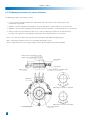
4-7-2 Adjusting procedures for sensor locations
The adjusting procedures are presented as follows:
1. Loosen each two screws fixing a disk with an origin slit and dogs for limit switch 1 and 2 respectively as easily
as turning the dogs by hand.
2. Adjust the clockwise actuating position turning the dog for the limit switch 2, and fix it with the two loosened screws.
3. Adjust the counter-clockwise actuating position turning the dog for the limit switch 1, and fix it with the two loosened screws.
4. Turn the actuator at low speed while the origin sensor is active, and find the best position for the origin monitoring
the output of the origin sensor. After finding the origin position, fix the disk with the two loosened screws.
Note 1: The screws for the disk and the dogs are fixed temporarily. Fix them tightly after adjusting above.
Note 2: Fixing measure against looseness is recommended after fixing the screws.
Note 3: Confirm generation of sensor signals at proper actuator position during test run after the adjusting.
Fixing screws for limit switch 2:2-M3
Fixing screws for limit switch 1:2-M3
Limit switch 2
Limit switch 1
Origin sensor
Fixing screws for origin disk: 2-M3
Origin disk
Fixing range of screws for origin disk
Fixing range of screws for limit switch
36
Dog for limit switch 1
Dog for limit switch 2
Chapter 4 Options
4-7-3 Movable range for each limit switch
The mechanical limit switches have limits for the movable range of the actuator as follows:
Movable range for limit switch 1
Moveable range for limit switch 2
Moveable range
Actuating positionActuating position
Movable range for limit switch 1
Moveable range for limit switch 2
Moveable range
Actuating positionActuating position
Moveable range
!
CAUTION
Do not overrun beyond the moveable range mentioned above.
The over running may damage the limit switch resulting mechanical failure and physical injury.
Harmonic Drive LLC 800-921-3332
37
Chapter 4 Options
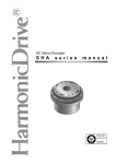
4-8 Accessories
4-8-1 For HA-800 driver
•
Extension cable
Optional extension cables of 3m/5m/10m long are available for connecting an actuator and a driver:
1) for a motor including brake wires, 2) for an incremental encoder system.
Ordering model:
for a motor:
EWC-MB *==* - M08-TN
for an incremental encoder: EWC-E *==* - B04-3M14
Cable length
03
3m
05
5m
10
10m
•
Connector kit
Ordering Code: CNK-HA80A-S1
•
Communication cable: Communication between driver and PC Via RS-232C
Ordering Code: EWA-RS03
Note: RS-232C communication cable is user’s responsibility. Recommended cable is RS-232C cross cable with a DSUB female 9-pin
connector for driver: KRS-L09-2K or equivalent manufactured by Sanwa Supply.
4-8-2 For HDLLC driver
• Extension cable (Encoder: US)
Motor: EWC-MB ** – M08 – SP
Encoder : EWA – E ** – M16 – SP
** ------ Cable length: 03=3m, 05=5m, 10=10m
•
Connector kit
Ordering Code depends on the driver; please refer to the Data sheet.
•
Communication cable: Communication between driver and PC Via RS-232C
Ordering Code: SER-CK
38
Appendix 1 Unit conversion
Appendix 1 Unit conversion
This manual employs SI system for units. Conversion factors between the SI system and other systems are as follows:
(1) Length
SI systemm
Unit
ft.
in.
Factor
3.281
39.37
SI system m
(20)Linear speed
SI systemm/s
Unit
m/min
ft./min ft./s in/s
Factor
60196.93.28139.37
Unit ft. in.
Factor
0.3048
0.0254
Unit
m/min
ft./minft./sin/s
Factor 0.0167
5.08x10⁻³ 0.30480.0254
SI system m/s
(3) Linear acceleration
SI system
m/s2
Unit
m/min2 ft./min2 ft./s2in/s2
Factor 2.78 x10⁻⁴ 8.47x10⁻⁵ 0.30480.0254
2
2
2
2
Unit
m/min ft./min ft./s in/s Factor
3600
1.18x10⁴ 3.281 39.37
SI system
m/s2
(4) Force
SI systemN
Unit
kgf
lb(force)
oz(force)
Factor 9.81 4.45
0.278
Unit
kgf
lb(force)
oz(force)
Factor
0.102
0.2254.386
SI system N
(5) Mass
kg
SI system
Unit
lb.
oz.
Factor
2.205
35.27
Unit
lb.
oz.
Factor
0.4535
0.02835
SI system kg
(6) Angle
SI systemrad
Unit DegreeMinute
Second
Factor 0.01755
2.93x10-44.88x10-6
Unit
Degree
Minute
Second
Factor
57.3
3.44x1032.06x105
SI system
rad
Harmonic Drive LLC 800-921-3332
39
Appendix 1 Unit conversion
(7)
Angular speed
SI system
rad/s
Unit
deg/s deg/min
r/s r/min
Factor 0.017552.93x10-4 6.280.1047
Unit
deg/s d
eg/min
r/s r/min
Factor
57.3 3.44x10³ 0.1592 9.55
SI system
rad/s
(7)
Angular acceleration
SI system
rad/s2
Unit deg/s2deg/min2
Factor 57.3 3.44x10³
(9)
Unitdeg/s2deg/min2
Factor0.017552.93x10-4
SI system
rad/s2
Torque
SI system
N•m
Unit
kgf•m lb•ft
lb•in oz•in
Factor
9.81 1.356 0.11307.06x10-3
Unit
kgf•m lb•ft
lb•in oz•in
Factor
0.102 0.738
8.85 141.6
SI system
N•m
(10)
Moment of inertia
SI system
Unit kgf•m•s2kgf•cm•s2
Factor 0.102
10.2
kg•m2
lb•ft2lb•ft•s2lb•in2lb•in•s2
oz•in2oz•in•s2
3
23.73
0.7376
3.42x10 8.85 5.47x104141.6
Unit kgf•m•s2kgf•cm•s2lb•ft2lb•ft•s2lb•in2lb•in•s2oz•in2oz•in•s2
Factor9.81
0.0981
0.0421
1.3562.93x10-40.113 1.829x10-57.06x10-3
SI system
kg•m2
(11)Torsional spring constant, moment stiffness
SI system
N•m/rad
Unit
kgf•m/rad
Factor 0.102
kgf•m/arc min
kgf•m/deg
lb•ft/deg
lb•in/deg
2.97x10-51.78x10-30.0129 0.1546
Unit
kgf•m/rad
Factor 9.81
kgf•m/arc min
kgf•m/deg
lb•ft/deg
lb•in/deg
3.37x104562 77.6 6.47
SI system
40
N•m/rad
Appendix 2 Moment of inertia
Appendix 2 Moment of inertia
1.Calculation of mass and moment of inertia
(1) Both centerlines of rotation and gravity are the same:
The following table includes formulas to calculate mass and moment of inertia.
m: mass (kg); Ix, Iy, Iz: moment of inertia for rotation center of x-, y-, z-axis respectively (kg•m2);
G: distance from gravity center to the surface; p: specific gravity
Unit Length: m;
Object form
Cylinder
Mass, inertia, gravity center
Ix =
R
x
y
L
Iy =
1
m R2
2
θ
{ (
L
Ellipsoidal cylinder
z
x
y
Rectangular pillar
B z
π
BC L ρ
4
1
Ix =
m B2 + C2
16
Iy =
1 ⎛⎜ C2 L2 ⎞⎟
m
+
4 ⎜⎝ 4
3 ⎟⎠
2
R
y
}
Cone
x
G
L
(
(
1
Iz =
m(A
12
y
2
)
)
+B )
D
)
)
L2 ⎫
1 ⎧ 2
2
m ⎨ R1 − R 2 + ⎬
3 ⎭
4 ⎩
m=
4
π R3 ρ
3
(
)
2
m R2
5
(
3
Iz =
m (4R
80
G=
Square pipe
1
m B2 + C2
12
1
Iy = m C2 + A 2
12
(
(
π
π R2 L ρ
3
3
Ix =
m R2
10
3
Iy =
m 4R2 + L2
80
R
2
m = A BC ρ
)
m=
z
)
2
Iz =
I=
L ⎞⎟
1 ⎛⎜ B
+
m
⎜
3 ⎟⎠
4 ⎝ 4
Ix =
C
A
)
m=
Iz =
x
L
Ball
(
C
L
y
1
Iθ = m
12
× 3R 2 1 + cos 2θ + L2sin 2θ
2
1
2
2
m R1 − R 2
2
L2 ⎫
1 ⎧ 2
2
Iy = m ⎨ R1 − R 2 + ⎬
3 ⎭
4 ⎩
Ix =
R1:outer, R2:inner
m = π R2 L ρ
R
(
x
R2
2
m = π R1 − R2 L ρ
R1
1 ⎛⎜ 2 L2 ⎞⎟
m R +
3 ⎟⎠
4 ⎜⎝
Inertia: kg・m
Mass, inertia, gravity center
z
1 ⎛
L2 ⎞⎟
Iz = m ⎜ R 2 +
4 ⎜⎝
3 ⎟⎠
Slanted cylinder
B
Object form
Circular pipe
m = πR 2 Lρ
z
Mass: kg;
L
4
1
m (B - D)2 + D2
3
1
Iy = m A 2 + (B - D)2 + D2
6
1
Iz = m A 2 + (B - D)2 + D2
6
Ix =
x
A
2
m = 4AD(B - D )ρ
B z
2
2
)
+L )
y
{
{
{
}
}
}
Harmonic Drive LLC 800-921-3332
41
Appendix 2 Moment of inertia
Mass, inertia, gravity center
Object form
Rhombus pillar
B
C
x
y
A
z
G
C
x
•
y
A
)
(
(
Iz =
Isosceles triangle
pillar
B
1
ABC ρ
2
1
Ix =
m B2 + C2
24
1
Iy =
m C2 + 2A2
24
m=
z
1
m B2 + 2A2
24
(
)
x
B
)
1
ABC ρ
2
1 ⎛⎜ B 2 2 2 ⎞⎟
Ix =
m
+ C
⎟
12 ⎜⎝ 2
3
⎠
y
A
Right triangle pillar
1 ⎛ 2 2 2 ⎞
m⎜ A + C ⎟
12 ⎝
3
⎠
⎛
1 ⎜ 2 B2 ⎞⎟
m A +
Iz =
2 ⎟⎠
12 ⎜⎝
C
G=
3
Iy =
z
C
B
G2
A
Iz =
1 ⎛ 2 5 2 ⎞
m ⎜ A + B ⎟
12 ⎝
2
⎠
1
ABCρ
2
1
Ix =
m B2 + C2
36
1 ⎛ 2 2 2 ⎞
Iy =
m⎜ A + C ⎟
12 ⎝
3 ⎠
m=
)
(
G1
x
3 3
AB2 ρ
2
5
Ix =
m B2
12
1 ⎛ 2 5 2 ⎞
Iy =
m ⎜ A + B ⎟
12 ⎝
2
⎠
m=
z
B√3
m=
Mass, inertia, gravity center
Object form
Hexagonal pillar
y
1 ⎛ 2 2 2 ⎞
m⎜ A + B ⎟
12 ⎝
3
⎠
C
B
G1 =
G2 =
3
3
Iz =
Example of specific gravity
The following tables show references of specific gravity.
Confirm the specific gravity for the material of the drive load.
Material
Gravity
Material
Gravity
Material
Gravity
SS45C
7.86
Bronze
8.5
Epoxy resin
1.9
SS41C
7.85
Aluminum
2.7
ABS
1.1
Cast steel
7.85
Duralumin
2.8
Silicon resin
1.8
Cast iron
7.19
Teflon
2.2
Polyurethane rubber 1.25
Copper
8.92
Fluorocarbon resin
2.2
Chloroprene rubber
1.15
(2) Both center lines of rotation and gravity are not the same:
The following formula calculates the moment of inertia when the rotary center is different from the gravity center.
I = I g + mF 2
2
I: Inertia when both
. centers are not the same (kg•m )
Ig: Inertia when both centers are the same (kg•m2)
Calculate with formulas described in (1).
m: Mass (kg)
F: Distance between rotary center and gravity center (m)
F
(3) Inertia of linearly moving objects
The inertia, converted to the actuator axis, of linear moving
objects is calculated with the formula as follows:
I=m
( )
P 2
2π
I: Inertia of linearly moving objects, converted to the actuator axis (kg•m2)
m: Mass (kg)
P: Displacement per one revolution of actuator (m/rev)
42
Rotary
center
Gravity
center
Moment of inertia
2
Inertia of cylinder
The moment of inertia of a cylinder may
be obtained from the graphs to the right.
The above graph is
applied for aluminum
(specific gravity: 2.7)
and the lower for steel
(specific gravity: 7.85).
The double-dot-chain lines
indicate the allowable inertia
for each actuator.
(Example)
Material: Aluminum
Diameter: 100mm
Length: 7mm
Form: cylinder
As the diameter is 100mm,
the radius is 50mm.
Therefore, the above graph
would indicate that the inertia is:
Approx.1.9X10-4kg•m2
(Exact value: 0.000186 kg•m2)
Harmonic Drive LLC 800-921-3332
43
Warranty Period & Terms
The FHA-C series actuators are warranted as follows:
• Warranty period
Under the condition that the actuator are handled, used and maintained properly followed each item of the documents and the manuals, all the FHA-C series actuators are warranted against defects in workmanship and materials for the shorter period of either one year after delivery or 2,000 hours of operation time.
• Warranty terms
All the FHA-C series actuators are warranted against defects in workmanship and materials for the warranted period. This limited warranty does not apply to any product that has been subject to:
(1) user's misapplication, improper installation, inadequate maintenance, or misuse.
(2) disassembling, modification or repair by others than Harmonic Drive LLC.
(3) imperfection caused by the other than the FHA-C series actuator and the servo driver.
(4) disaster or others that is not the responsibility of Harmonic Drive LLC
All products are warranted to be free from design or manufacturing defects for a period of one year from the
date of shipment. Such items will be repaired or replaced at the discretion of Harmonic Drive LLC. The seller
makes no warranty, expressed or implied, concerning the material to be furnished other than it shall be of the
quality and specifications stated. The seller’s liability for any breach is limited to the purchase price of the product. All
efforts have been made to assure that the information in this catalog is complete and accurate. However, Harmonic
Drive LLC is not liable for any errors, omissions or inaccuracies in the reported data. Harmonic Drive LLC reserves
the right to change the product specifications, for any reason, without prior notice.
44
Harmonic Drive LLC
Boston US Headquarters
247 Lynnfield Street
Peabody, MA 01960
New York Sales Office
100 Motor Parkway
Suite 116
Hauppauge, NY 11788
California Sales Office
333 W. San Carlos Street
Suite 1070
San Jose, CA 95110
45
Chicago Sales Office
137 N. Oak Park Ave., Suite 410
Oak Park, IL 60301
Group Companies
Harmonic Drive Systems, Inc.
6-25-3 Minami-Ohi, Shinagawa-ku
Tokyo 141-0013, Japan
T: 800.921.3332
T: 978.532.1800
F: 978.532.9406
Harmonic Drive AG
Hoenbergstrasse, 14, D-6555
Limburg/Lahn Germany
www.HarmonicDrive.net
Harmonic Drive is a registered trademark of Harmonic Drive LLC.
Rev 20150430