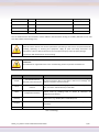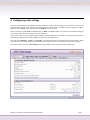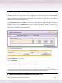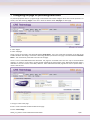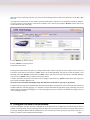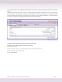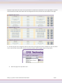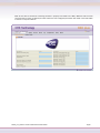
1
 BSD/BSD Plus
APPLICATION NOTE How to create a Web Scada Presentation CRE Technology believes that all information provided herein is correct and reliable and reserves the right to update at any time. CRE Technology does not assume any responsibility for its use. E & O E. CRE Technology 130 Allée Charles‐Victor Naudin Zone des Templiers ‐ Sophia Antipolis 06410 BIOT ‐ FRANCE Phone: + 33 (0)4.92.38.86.82 ‐ Fax: + 33 (0)4.92.38.86.83 www.cretechnology.com ‐ [email protected] SARL au Capital de 300.000 Euros ‐ RCS Antibes: 7488 625 000 15 N°TVA FR54 488 625 583 Date Version Decemberr 12th 2009 1.0 Comments
By First version created
MM
You can download this documentation and the different documentation relating to the BSD / BSD Plus on our web site: http://www.cretechnology.com/ . NOTE: Read this entire manual and all other publications pertaining to the work to be performed before installing, operating, or servicing this equipment. Apply all plant and safety instructions and precautions. Failure to follow instructions can cause personal injury and/or property damage. Contact your CRE distributor for course training. Trademarks: All trademarks or registered marks in this manual belong to their respective manufacturers. Term TCP/IP Extract Description TCP (Transmission Control Protocol) is a set of rules used along with Transmission Control the Internet Protocol (IP) to send data in the form of message units Protocol/ Internet Protocol
between computers over the Internet. HTTP Hyper Text Transfer Protocol HTTP is a set of rules for exchanging files (text, graphic images, sound, video, and other multimedia files) on the Web. DHCP Dynamic Host Configuration Protocol DHCP is a standard protocol that automates the process of configuring network hosts by allowing hosts to obtain IP addresses and configuration parameters Gateway A device that makes it possible to transfer data between networks of different kind, e.g. Modbus/RTU and Modbus/TCP. Template Describes a Modbus slave device, as a collection of groups and parameters. Device A Modbus slave unit that is connected to the BSD Plus. Table 1 : Terminology A61Zx_en_How to create a Web Scada Presentation 2/14 Table of contents 1 Introduction .......................................................................................................................... 4 2 Equipment ............................................................................................................................ 4 3 Getting started ..................................................................................................................... 5 4 Configuring serial settings .................................................................................................... 6 5 Install or create a device template ........................................................................................ 7 6 Define the Device(s) connected to BSD/BSD Plus ................................................................... 7 7 Configuring the page for presenting data values .................................................................. 9 8 Configure the data to be presented ...................................................................................... 10 9 References ........................................................................................................................... 14 A61Zx_en_How to create a Web Scada Presentation 3/14 1 Introduction This application note describes how to create a configuration to present live data values through the Web‐server in the BSD / BSD Plus module. The BSD / BSD Plus module acts as a bridge from Modbus TCP to Modbus RTU, making it possible for a Modbus TCP based controller to connect with Modbus RTU based devices. The BSD / BSD Plus is a device that is not only designed to provide the bridging function, but to also handle alarm management, data‐logging as well as providing a web‐based user interface for accessing data. The web‐based user‐interface can be used to present data of the instrument or system the BSD / BSD Plus is connected with. This application note describes how to create such a configuration. The BSD / BSD Plus has been successfully configured for many applications and CRE publishes device templates for several devices. Please contact CRE Technology for further information regarding available device templates. 2 Equipment ‐
BSD / BSD Plus Modbus version 3.0 or later ‐
Personal computer with a Web browser ‐
Modbus RTU compatible device (including manual describing available Modbus registers) ‐
Ethernet network (including connections between the BSD / BSD Plus and the PC) A61Zx_en_How to create a Web Scada Presentation 4/14 3 Getting started This application note assumes that the BSD / BSD Plus module is properly installed and accessible over the Ethernet network interface. If this is not the case, please refer to the step‐by‐step installation of the BSD / BSD Plus for further instructions, which describes the required steps to install this properly and access the unit over an Ethernet network. Open your web browser and enter the address path (IP address of the module) to connect to the BSD / BSD Plus module. Login as administrator (default login and password are both “admin”) by entering the correct user and password information. When properly logged in, the default welcome page will be shown to you (as below in the picture), if no earlier configuration has been done. If there already is a configuration stored in the module, a page presenting information corresponding to that configuration will be shown. A61Zx_en_How to create a Web Scada Presentation 5/14 4 Configuring serial settings The serial communication link between the BSD / BSD Plus module and the equipment connected to it need to be configured for the same serial settings to be able to properly communicate. To modify the serial settings in the BSD / BSD Plus, select “Setup” in the menu and select “Modbus” in the sub‐menu. Select transmission mode “RTU” for Modbus RTU or “ASCII” for Modbus ASCII. This needs to be selected according to the communication protocol used by the connected device. The physical media can be selected to either RS‐485 or RS‐232. Make sure the selection corresponds to the physical media being used between the BSD / BSD Plus and the connected equipment. Also select the “Baudrate”, “Parity” and “Stop bit”, accordingly with what is preferred for the communication. Make sure all devices are configured for the same settings. If this is not the case, communication will not work properly. Once we are done, press the “save settings” button at the bottom of the page to store the configuration. A61Zx_en_How to create a Web Scada Presentation 6/14 5 Install or create a device template The BSD / BSD Plus uses device templates when a configuration is created. A template stores information about available parameters within a device or a system. This application note does not describe how to create a template, but this is described in a separate document (How to create a device template). That application note is available for download at http://www.cretechnology.com. The first step in the configuration is to make sure we have a template installed in the BSD / BSD Plus unit. In the menu, select “Configuration” and then “Templates” in the sub‐menu. This brings up the configuration page for templates. If no templates earlier have been installed in the unit, the list of available templates will be empty. To install an existing template from disk, press the “add template” button (or to create a new template, follow the instructions in the application note mentioned above), and then click the restore button for the new template. This will bring up a dialog window which is used to browse to the template file. To get templates, just click this link 1. Click “Configuration” in the menu 2. Select “Templates” in the sub menu 3. Click “add template” 4. Enter a name and click “ok” (This name will be changed after restore) 5. To upload template from disk click “restore” 6. Browse the template file and click “restore” In this application note we will be using a template file for a Modbus RTU based I/O node called BSD / BSD Plus I/O Extender. Once we have installed the template for this unit the page looks as the picture below. 6 Define the Device(s) connected to BSD/BSD Plus A61Zx_en_How to create a Web Scada Presentation 7/14 Next we need to define the device(s) that we have connected to the BSD / BSD Plus. Click “Devices” in the sub‐menu and then press “add device” at the bottom of the configuration page for devices. 1. Go to “Devices” 2. Click "add device” Assign a name to the device in the field at the top of the page and select the template that represents the device from the drop‐down list. Also set the Modbus Slave address of the device in the edit field and press save settings. 1. Assign a name to the device 2. Select device template 3. Set the Modbus address 4. Click “save settings” The device shall now have been added to the Device Configuration list. A61Zx_en_How to create a Web Scada Presentation 8/14 7 Configuring the page for presenting data values To present equipment data on a page through a web‐browser we need to configure which data shall be presented. To do this, start with selecting “Pages” in the menu. Press the button called “add page” to add a page. 1. Click “Pages”
2. Click “add page”
Assign a name to the page in the edit field labelled “Page Name”. This is the name that will appear as the title of the browser window. Also assign a name that is describing the data presented on the page in the field labelled “Overview Name”. This name will be presented in the menu of the page. There is also a field labelled Advanced Overview. This page has restricted access and can only be accessed when logged in as admin or super admin. Further details regarding the functionality of the Advanced Overview page is described in the user manual of the BSD / BSD Plus. If the Advanced Overview page will be used to present data, a name is also set here.
1. Assign a name to the page 2. Set a name to describe the data viewed on the page 3. Click “save settings” A61Zx_en_How to create a Web Scada Presentation 9/14 When the name of the page has been set, press the save settings button to store the information in the BSD / BSD Plus unit. The page that presents data can also show a picture describing the installation or the equipment containing the data. To store a picture in the module it needs to be uploaded. This is done by pressing the “Browse” button next to the name fields at the top of the page. 1. Click “Browse” to select a picture” 2. Click “upload” to save the picture 3. Preview of the picture Pressing the browse button will open up a dialog window which makes it possible to locate a picture file on the local hard drive. Select the file and press the “Open” button of the dialog window. The path to the file will appear in the text field next to the “Browse” button after the “Open” button was pressed. To store the picture in the BSD / BSD Plus unit, press the “upload” button as shown in the picture above. A smaller preview of the picture will show in the rectangle to the left of the “upload” button when the picture has been stored in the BSD / BSD Plus unit. The picture can not be wider then 870px, larger then 50k and it needs to be in .gif, .png or .jpg format! A default welcome page was presented when we started creating this configuration and accessed the web interface of the BSD / BSD Plus unit after logging in. It is possible to replace that welcome page with a page presenting data as the default page to be loaded after logging in. To select the page that we are creating as the default start page, press the “set as start page” button. 8 Configure the data to be presented Once the edit button has been pressed, a page will be shown where we can configure the parameter that we want to present in that data field. Start by selecting the device where the parameter will be stored in the drop down menu at the top (all configured devices will be available here). Then select the parameter group the data value is stored in. In A61Zx_en_How to create a Web Scada Presentation 10/14 the example below we are configuring a temperature value stored in the parameter group named “Temperature Input”. In the description field it is possible to enter a name describing the data that will be shown and in our case we have a temperature value. Assume the value represents the temperature of a boiler. The description field makes it possible to enter an appropriate name that is easier for a user to relate to, such as “Boiler temperature”. The button with the arrow can also be used to copy the default name to the parameter description. 1. Select the device from where the data parameter should be read 2. Select the group where the data parameter is to be found 3. Select the parameter 4. Enter a name for the point, or copy using down arrow at end of parameter row 5. Select how data should be presented 6. Click “save settings” A61Zx_en_How to create a Web Scada Presentation 11/14 Repeat the steps above and create as many parameters as preferred for presentation on the page. Below is a picture that shows what it would look like when we have configured some more parameters for presentation on the page. To view the page we have configured, select the title name of the page that will be available from the drop down menu at the top left of the window as shown in the picture below. Select the page and press the go button. 1. Select the page in the drop down menu A61Zx_en_How to create a Web Scada Presentation 12/14 Now we are done. If the device containing the data is properly connected to the BSD / BSD Plus and the serial communication properly configured, the data values for each configured parameter shall show in the data tables as shown in the picture below. A61Zx_en_How to create a Web Scada Presentation 13/14 9 References Object Publisher
Version BSD / BSD Plus Technical Doc. CRE Technology
1.2
BSD / BSD Plus Quick Start Guide CRE Technology
1.0
How to create a device template CRE Technology
1.0
A61Zx_en_How to create a Web Scada Presentation 14/14