1
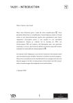
SCR2.0 Synchroscope and synch check relay User manual - Technical documentation www.cretechnology.com www.cretechnology.com A60 X2 9 0020 B EN user manual technical documentation www.cretechnology.com Content 1 PRESENTATION........................................................................................................................................................................5 2 INSTALLATION..........................................................................................................................................................................6 3 2.1 Environmental Requirements ..........................................................................................................................................6 2.2 Unpacking .......................................................................................................................................................................6 2.3 Preparation .....................................................................................................................................................................6 2.4 Mounting the Unit...........................................................................................................................................................6 2.5 Wiring the Unit................................................................................................................................................................6 HUMAN-MACHINE INTERFACE .................................................................................................................................................9 3.1 LED display ......................................................................................................................................................................9 3.2 Digital display ................................................................................................................................................................ 10 4 PROGRAMMING .................................................................................................................................................................... 11 5 OPERATION ........................................................................................................................................................................... 12 6 7 5.1 Power-up ...................................................................................................................................................................... 12 5.2 Status information ........................................................................................................................................................ 12 5.3 Synchronization checking .............................................................................................................................................. 12 OTHER FEATURES .................................................................................................................................................................. 14 6.1 Dead Bus Enable............................................................................................................................................................ 14 6.2 Synchronization checking delay ..................................................................................................................................... 14 MISCELLANEOUS ................................................................................................................................................................... 15 7.1 Troubleshooting ............................................................................................................................................................ 15 7.2 Declaration of conformity.............................................................................................................................................. 15 7.3 Technical specifications ................................................................................................................................................. 15 user manual technical documentation A60 X2 9 0020 B EN www.cretechnology.com DOCUMENT CONTROL Version Date A nd Changed by Details July 22 , 2014 A. Mesnard First edition B Aug. 25 , 2014 th A. Mesnard Minor, chronogram completed 4 user manual technical documentation A60 X2 9 0020 B EN 1 www.cretechnology.com PRESENTATION The unit SCR2.0 is a metering and control module used in manual synchronization and protection panels. It monitors the voltage and frequency of two power networks and shows the measured values on its 3-digit 7segment display. The 24-led circular synchroscope indicates the true instantaneous phase angle between the networks. It is powered by a battery. It can check the synchronization between a generator and its busbar, or a generator busbar and mains. The measured/calculated parameters are: Generator phase-to-neutral voltage Generator frequency Busbar phase-to-neutral voltage Busbar frequency Busbar-generator frequency difference Busbar-generator voltage difference Busbar-generator phase difference WARNING THIS UNIT DOES NOT CHECK THE PHASE SEQUENCE First make sure the two AC supplies feature the same sequence of the phases Failure to follow this instruction can damage the equipment The unit is installer-friendly and user-friendly. In addition, programmable parameters give an extended control over the operation. The programmed values are stored in a non volatile memory; thus all information is retained even in the event of complete loss of power. Designation: SCR 2.0 / A60 X2 5 A60 X2 9 0020 B EN 2 user manual technical documentation www.cretechnology.com INSTALLATION The unit is designed for panel mounting, which provides user with access only to the front panel. 2.1 Environmental Requirements Operating temperature: -20°C (-4°F) to 70°C (158°F) Storage temperature: -30°C (-22°F) to 80°C (176°F) Maximum humidity: 95% without condensation 2.2 Unpacking Make sure the packaging contains: the unit two clamping sets packaged apart a delivery bill Unpack and keep the packaging in event of return. Make sure the unit does not show scratches or visible defaults. Otherwise describe them on the bill. 2.3 Preparation 1. 2. 2.4 Cut out the panel to 92x92 mm minimum (3.6 in. x 3.6 in.) Make sure the cut-out is smooth and clean Mounting the Unit Tool: cross-head screwdriver size 1. To mount the unit: 3. Pass the unit through the panel 4. In the rear, insert the tab of a clamping set into the hole on one side of the unit, and screw the unit against the panel 5. Repeat on the other side 6. 2.5 Tighten equally on both sides Wiring the Unit Tool: insulated screwdriver Ø2.5 mm (0.1 in.), tightening torque: 0.8 Nm (7 lb-in) max. Wires: 0.2…2.5 mm² (AWG 25 …14) Accessories: 7-terminal cable connector, protective gloves, carpet if the floor is wet WARNING THE UNIT IS NOT PROTECTED Use external fuses for Busbar phase: L1, Generator phase: L1, Battery positive: BAT(+). Install the fuses as nearly as possible the unit, in a place easily accessible to the user. Fuse rating: 6A. The disconnection device must NOT be fitted in a flexible cord. Failure to follow this instruction may damage the unit 6 A60 X2 9 0020 B EN user manual technical documentation !l l www.cretechnology.com DANGER HAZARD OF ELECTRIC SHOCK, EXPLOSION OR ARC FLASH The unit must only be installed and serviced by qualified electrical personnel Apply appropriate personal protective equipment (PPE) and follow safe electrical work practices Turn off power before installing or removing fuses, and before installing the unit Use a properly rated voltage sensing device to confirm the power is off Do not use renewable link fuses in fused switch Failure to follow this instruction will result in death or serious injury LOWER CONNECTOR: digital inputs and outputs, unit power supply To check the connection, press the Lamp test button. (The led SYNCH OUT is not tested.) 7 A60 X2 9 0020 B EN user manual technical documentation www.cretechnology.com UPPER CONNECTOR: phase L1 and neutral on both sides of the breaker 1. 2. Make sure the cable connector is NOT plugged on the upper connector Take on protective gloves 3. Connect the wires on the cable connector in accordance with the National Wiring Regulations Term Function Technical data Description 1 GENERATOR PHASE-L1 Generator phase input, Connect the generator phase there. The generator 0-300VAC phase voltage upper and lower limits are programmable 2 unused 3 GENERATOR NEUTRAL Input, 0-300VAC Neutral terminal of the generator phase 4 unused 5 BUSBAR NEUTRAL Input, 0-300VAC Neutral terminal of the busbar phase 6 unused 7 BUSBAR PHASE-L1 Busbar phase input, Connect the busbar phase there. The busbar voltage 0-300VAC upper and lower limits are programmable 4. 5. Plug the cable connector onto the upper connector Lock the rear door. !l EXPOSED TERMINALS l DANGER Do not touch or use non-insulated tools near terminals L1 and N. These terminals are unprotected and will expose the user to dangerous voltages Failure to follow this instruction will result in death, serious injury or equipment damage 8 user manual technical documentation A60 X2 9 0020 B EN 3 www.cretechnology.com HUMAN-MACHINE INTERFACE The information is displayed as follows: 3.1 LED display The Synchronoscope shows the instantaneous phase difference between the generator voltage and the busbar voltage. When both networks are synched, the uppermost led at 12:00, marked 0º, is ON When the generator frequency is higher than the busbar frequency, the synchroscope turns clockwise When the generator frequency is lower than the busbar frequency, the synchroscope turns counterclockwise. The Status shows the current status of the busbar and generator voltages and the synchronization checking status. The SYNCH OUT illuminates when the SYNCH CHECK relay output is ON. SCR 2.0 indicates the nature of the displayed value by lighting one unit led in three (VAC, Hz or degree). LED Colour Description Synchroscope Red or When both busbar and generator voltages are in range, the synchroscope illuminates. amber Only one of the leds turns on at a time. The led indicates the phase difference between the generator phase and the busbar phase. Right-hand side illuminated: the generator phase is leading (in advance) the busbar Left-hand side illuminated: the generator phase is lagging Light cycling clockwise: generator frequency > busbar frequency Light cycling counter-clockwise: generator frequency < busbar frequency BUS status Amber ON when the busbar voltage is in range GEN status Amber Output state Amber OFF if the generator voltage is out of range Blinks if the generator voltage is in range, but SCR2.0 is waiting for a checking request Steadily ON if the synchronization coupling is enabled ON when the SYNCH CHECK relay is energized. The synchronization checking can be initiated or terminated: locally by pressing the SYNCH button remotely via the SYNCHRONIZATION (CHECK) ENABLE input signal The led SYNCH OUT is not energized by the Lamp test Unit Red SCR2.0 selects VAC, Hz or Deg. depending on the position in the MENU 9 A60 X2 9 0020 B EN 3.2 user manual technical documentation Digital display The unit has a three-digit seven-segment display. It shows on request: Readings (symbol, then value) in a sequence Programmable parameters (number, then value) in a sequence Scan the various readings using the MENU button. The sequence is: U1: busbar phase-to-neutral voltage U2 : generator phase-to-neutral voltage dU: voltage difference between busbar and generator phases F1: busbar frequency F2: generator frequency dF: frequency difference between busbar and generator deg: phase difference between busbar and generator phases (degrees) Hold down the button to display the value. 10 www.cretechnology.com A60 X2 9 0020 B EN 4 user manual technical documentation www.cretechnology.com PROGRAMMING WARNING RISK OF UNINTENDED EQUIPMENT OPERATION Set the parameters to values that do not endanger your setup. We strongly recommend to keep the parameter #9 to 1 Failure to follow this instruction can damage equipment The program is used mainly to specify operational limits. To enter the program, press the MENU button for 5 seconds. During programming, the unit still monitors and shows the statuses. Thus, the parameters can be modified anytime, even while the generator is running. When the MENU button is pressed, the display shows the parameter number, when it is released the display shows the program parameter value. The first program number is “000”. Press the MENU button to switch to next parameter. After the last parameter, the display cycles to the start. Press the / keys to increase/decrease the value. Hold them down to increase/decrease the value by steps of 10 units. The program display goes off automatically after 20 seconds if no button or key is pressed. # 0 1 2 Definition Unit Typical Busbar Voltage Low Limit V 100 Busbar Voltage High Limit V 500 Gen. Voltage Low Limit V 180 3 Gen. Voltage High Limit V 270 4 Frequency difference Hz 1.0 5 Voltage difference V 10 deg 5 7 Hysteresis Voltage V 8 8 Synchronization checking delay sec 3 9 Synchronization checking after coupling - 6 Phase difference 1 Status or description Under this limit, the busbar voltage is invalid (out of range) Over this limit, the busbar voltage is invalid (out of range) Under this limit, the generator voltage is invalid (out of range) Under this limit, the SYNCH CHECK relay cannot remain energized Over this limit, the generator voltage is invalid (out of range) Over this limit, the SYNCH CHECK relay cannot remain energized If the frequency difference between the busbar and the generator is above this limit, the synchronization is denied If the difference between the busbar and the generator voltages is above this limit, the synchronization is denied If the phase difference between the busbar and the generator voltages is above this limit, the synchronization is denied To prevent faulty decisions, you can set a hysteresis to the busbar and generator voltage limits. Recommended value: 8 V. For example, if the busbar voltage decreases, it goes out of range at P_000, whereas it returns in range at P_000 + P_007. Timer launched after the generator voltage is in range (set by parameters P_002 and P_003) and the synchronization checking is enabled. Refer to OTHER FEATURES. 0: the SYNCH CHECK relay remains energized 1: the unit continues to check the synchronization 11 A60 X2 9 0020 B EN 5 user manual technical documentation www.cretechnology.com OPERATION CAUTION RISK OF ERRONEOUS MEASUREMENTS Ground the engine body Failure to follow this instruction result in incorrect measurements 5.1 Power-up The unit is designed for continuous operation powered by the generator battery voltage (12/24VDC). It shuts off its displays after 1 mn if there is no voltage at the AC inputs and if no button is pressed. It starts to monitor when a voltage is applied to either generator voltage input or busbar voltage input, or any front panel button is pressed. The synchroscope illuminates if both generator and busbar phase voltages are in range. Otherwise it turns off to prevent the display of worthless information. 5.2 Status information Refer to HUMAN-MACHINE INTERFACE. 5.3 Synchronization checking The synchronization checking is ordered either locally by pressing the SYNCH button or remotely via the input signal SYNCHRONIZATION (CHECK) ENABLE Then, the unit is allowed to close the relay output if the networks are synched. Otherwise it does not close the relay even if the networks are synched. For a quick checking after the generator start, connect the SYNCHRONIZATİON (CHECK) ENABLE input signal to the battery negative. To let the generator stabilize (or even heat up if needed), program a presynchronization delay (P_08). Refer to Synchronization checking delay. The synchronization checking is not timed. The unit continues checking the synchronization until the conditions are met or the process terminated with the SYNCH button or the SYNCHRONIZATION (CHECK) ENABLE signal. A closed to open transition on the SYNCHRONIZATION CHECK ENABLE input causes the SYNCH RELAY to deenergize and the synchronization checking to terminate. Positions: Sync En. Contactor closed open SYN. EN. activated de-activated Once the SYNCH CHECK relay is energized, the synchronization checking goes on depending on the parameter P_09. Set it to 1. It is of the responsibility of the panel builder to use a quickly closing circuit breaker. On 0, the synchronization checking is disabled after closing the SYNCH CHECK relay, the relay output remains energized even though the circuit breaker fails to close. 12 A60 X2 9 0020 B EN user manual technical documentation Term Function mm BATTERY POSITIVE 8 www.cretechnology.com 9 10 BATTERY NEGATIVE DEAD BUS ENABLE Data +12 or 24VDC (9.0 … 33.0 V) 0VDC Input 11 SYNCHRON. (CHECK) ENABLE Input 12 13 unused SYNCH CHECK RELAY normally Breaking These outputs energize the circuit breaker. If the closed capacity: 16A/ generator voltage is out of range, or if the voltage, frequency or phase differences between generator SYNCH CHECK RELAY common 250VAC and busbar are not in range, it is not energized. SYNCH CHECK RELAY normally If the busbar is not powered up, use the DEAD BUS open ENABLE input signal. Refer to OTHER FEATURES. 14 15 Description Positive terminal of the DC supply. The unit operates on both 12V and 24V battery systems. Power supply negative connection. If the signal is active, the unit is allowed to energize the relay output even though the voltage level at the busbar input is below the set limit. Refer to OTHER FEATURES. To set the limit, refer to PROGRAMMING. Programming. If the signal is active, the unit is allowed to close the relay output when the conditions are met. Otherwise it does not energize the relay. The unit checks the synchronization only when both generator and busbar phase voltages are in range and the synchronization is enabled either with the SYNCH (CHECK) ENABLE signal or the SYNCH button. If both busbar and generator phase voltages are in range, the synchroscope illuminates. The synchroscope shows the phase difference between busbar and generator. The synchronization checking is the verification of the following conditions: the busbar phase voltage lies between limits set by P_00 and P_01 the generator phase voltage lies between limits set by P_02 and P_03 the frequency difference between the busbar and generator does not exceed the limit set by P_04 the voltage difference between the busbar and generator does not exceed the limit set by P_05 the phase difference between the busbar and generator does not exceed the limit set by P_06 If they are met for 4 consecutive busbar cycles, the SYNCH CHECK relay is immediately energized. 13 A60 X2 9 0020 B EN user manual technical documentation 6 OTHER FEATURES 6.1 Dead Bus Enable www.cretechnology.com It may be required to couple a generator to an unpowered bus (dead bus). This is especially the case for multi-generator synchronization systems, where one of the generators must feed the busbar to serve other generators as a reference for synchronization. When active, the DEAD BUS ENABLE input signal causes SCR2.0 to energize the SYNCH CHECK relay when all the following conditions are met: synchronization checking requested (either via input or button) the generator phase voltage is within limits set by P_02 and P_03 the busbar voltage is below the limit set by P_00. If the busbar voltage is above this limit, the SYNCH CHECK relay output is not energized even if the DEAD BUS ENABLE signal is active. Positions: Dead bus Contactor closed open 6.2 DEAD BUS activated de-activated Synchronization checking delay To let the generator stabilize (or even heat up if needed), program a pre-synchronization delay (P_08). When the generator voltage is in range, the unit is allowed to run this delay; at expiry, the synchronization checking can be accepted. Default factory setting: 3 seconds. If no delay is requested, set the parameter to 0. Example of remote/local request of synchronization checking: 14 A60 X2 9 0020 B EN user manual technical documentation 7 MISCELLANEOUS 7.1 Troubleshooting www.cretechnology.com AC voltages or frequency displayed on the unit are not correct (voltage accuracy: ± 3 V): Check the proper engine body grounding If there are faulty measurements only when the engine is running, there may be a faulty charging alternator or voltage regulator on the engine. Disconnect the charging alternator connection of the engine and check if the error persists If there are faulty measurements only when mains are present, the battery charger may be failed. Turn off the battery charger fuse and check. The unit is inoperative: The unit may be in sleep mode. Press any button to wake it up DANGER !l EXPOSED TERMINALSl Do not touch or use non-insulated tools near terminals L1 and N. These terminals are unprotected and will expose the user to dangerous voltages Failure to follow this instruction will result in death, serious injury or equipment damage Measure the DC supply voltage between terminals 8 and 9 at the rear of the unit. If they are in range, turn all the fuses off, then turn all the fuses on, starting from the DC supply fuse. Finally test the unit again. Lock the rear door. The digital display test shows only 1: check the power supply. If you return the unit, attach an RMA (available on the website). 7.2 Declaration of conformity The unit conforms to the following EEC directives 73/23/EEC and 93/68/EEC (low voltage) 89/336/EEC, 92/31/EEC and 93/68/EEC (electro-magnetic compatibility) Standards: EN 61010 (safety requirements) EN 50081-2 (EMC requirements) EN 50082-2 (EMC requirements) The CE mark indicates that this product complies with the European requirements for safety, health, and environ- mental and user protection. 7.3 Technical specifications Features: 24-led circular synchroscope Programmable ΔV, Δf, Δθ and parameters Front panel programming 15 A60 X2 9 0020 B EN user manual technical documentation www.cretechnology.com Voltage inputs: 1 phase of generator and 1 phase of busbar Synch check & dead bus enable input Auto power off Plug-in connection system for easy replacement Measurements: Busbar voltage: 300 VAC max. (Ph-N) Busbar frequency: 50/60 Hz Generator voltage: 300 VAC max. (Ph-N) Generator frequency: 0-100 Hz Other electrical data: Digital inputs: 0V (active inputs), withstand 30VDC DC Supply Range: 9.0 to 33.0 VDC Current Consumption: 100 mA (standby), 150 mA (all LEDs lit, Synch Check relay de-energized) Synch Check relay breaking capacity: 16 A / 250VAC Casing: Dimensions: 102x102x57 mm (4 in. x 4 in. x 2.3 in.) (width x height x in-panel depth) Mounting: Front panel Weight: 170 g (approx.) Material: High temperature ABS (UL94-V0, 100°C) Protection: IP65 from front panel, IP30 from the rear 16 A60 X2 9 0020 B EN user manual technical documentation www.cretechnology.com CRE TECHNOLOGY 130 allée Charles-Victor Naudin Zone des Templiers Sophia-Antipolis 06410 BIOT FRANCE Phone: +33 (0)4 92 38 86 82 Fax: +33 (0)4 92 38 86 83 Website: www.cretechnology.com Email: [email protected] Technical support: +33 (0)4 92 38 86 86 (office hours: 8.30AM - 12AM / 2PM - 6PM GMT +1) Email: [email protected] SKYPE: support-cretechnology.com (voice only) A worldwide coverage: Head Office: FRANCE Official Distributors Agents Check our entire distributors list around the world on www.cretechnology.com, button «DISTRIBUTORS». 17 A60 X2 9 0020 B EN user manual technical documentation www.cretechnology.com CRE TECHNOLOGY has provided the engine and generator industry for over 25 years with standard products and dedicated solutions for engine control, generator protection and paralleling. YOUR ACCOUNT & YOUR PRICES By creating your account, you’ll have access to all your personal data. All the prices of the new CRE TECHNOLOGY website correspond to your business rates. All application fields where power is the core resource of performance are covered by CRE TECHNOLOGY. The company is a reference in the industrial, marine and defense businesses. GET INFORMATION THE WAY YOU WANT IT Fill your cart by choosing the products you want and get all the information you need. EVERYWHERE WITH YOU Our very strong situation allows us to invest, feeding our ambition to be always more advanced, always closer to you. The coming years will see the broadening of our distribution network and of our innovative products portfolio. The new CRE TECHNOLOGY website is designed to be responsive to smartphones and touch tablets. It allows you to consult the documents related to the CRE TECHNOLOGY’s ranges of products. BECOME A CRE TECHNOLOGY DISTRIBUTOR 18