1
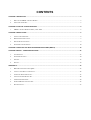
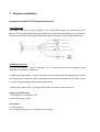
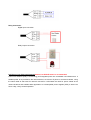
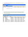
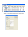
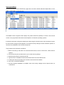
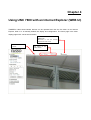
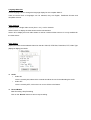
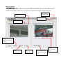
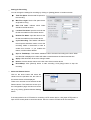
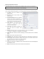
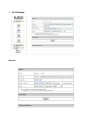
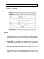
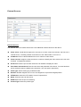
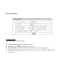
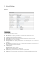
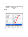
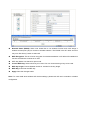
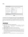
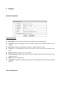
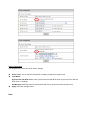
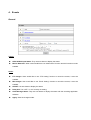
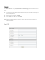
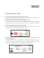
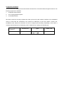
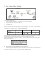
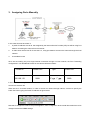
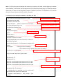
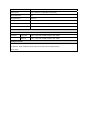
MPEG-4 Vandal Dome UNC 7800 series User’s Manual Version: 1.5 Date: 08/08/2008 CONTENTS CHAPTER 1 INSTRUCTION .............................................................................................................................................. 3 1. WHAT IS THE MPEG-4 VANDAL DOME?................................................................................................................ 3 2. ADVANCED FEATURES ........................................................................................................................................... 3 CHAPTER 2 PHYSICAL CHARACTERISTICS.................................................................................................................. 5 1. MPEG-4 VANDAL DOME CAMERA, UNC 7800..................................................................................................... 5 CHAPTER 3 INSTALLATION ............................................................................................................................................. 6 1. INSTALLATION PREVIEW........................................................................................................................................ 6 2. HARDWARE INSTALLATION.................................................................................................................................... 7 3. SOFTWARE INSTALLATION ..................................................................................................................................... 9 4. NETWORK CONFIGURATION ................................................................................................................................ 10 CHAPTER 4 USING UNC 7800 WITH AN INTERNET EXPLORER (WEB UI) ................................................................ 15 CHAPTER 5 WEB UI – CONFIGURATION PAGE ........................................................................................................... 22 1. A/V SETTINGS ..................................................................................................................................................... 23 2. NETWORK SETTINGS ........................................................................................................................................... 30 3. SYSTEM ............................................................................................................................................................... 35 4. EVENTS ............................................................................................................................................................... 39 APPENDIX A .................................................................................................................................................................... 43 1. BROADBAND CONNECTIONS Q&A...................................................................................................................... 43 2. CASE 1 USING DEFAULT SETTINGS ..................................................................................................................... 46 3. ASSIGNING PORTS MANUALLY ........................................................................................................................... 47 4. USING 2 OR MORE PUBLIC IPS ............................................................................................................................. 48 5. UPGRADING FIRMWARE ...................................................................................................................................... 49 6. I/O & COM PORT CONNECTORS ......................................................................................................................... 52 7. SPECIFICATIONS .................................................................................................................................................. 53 Chapter 1 Instruction 1. What is the MPEG-4 Vandal Dome? The MPEG-4 Vandal Dome is an Internet-based digital video surveillance device with a built-in Web server. It uses TCP/IP to distribute compressed live video over a Local Area Network (LAN) and/or the Internet through an Ethernet connection. The vandal dome is configured and manipulated using the Web-based User Interface (Web UI) in Microsoft Internet Explorer ™. The vandal dome contains an MPEG-4 image compression chipset capable of delivering streaming, constant or variable bit rate MPEG-4 video over the network in real-time. 2. Advanced Features Built-in HTTP Web Server. IP address assignment via IP Installer Software or Web UI. ActiveX control for Microsoft Internet Explorer ™ providing maximum performance. Provide Video conference function. Provide recording functions on remote host or storage devices. Support Wireless communication standard. (Optional Wireless Model) Support some models of PTZ control protocols. DDNS support for dynamic IP application. Multi-tiered access control. Remotely upgradeable firmware and Web UI. Control of server operations through CGI based scripts for easy integration. Provide Motion detection, E-Mail / FTP settings and Alert for management. Low power, fan-less device with hardware watchdog support providing a robust system for critical environments. MPEG-4 and MJPEG video compression formats. 30/25 fps @ Full D1 (720 x 480 / 720 x 576) resolution. Video stream supported by many media players including Quicktime ™. Chapter 2 Physical Characteristics 1. MPEG-4 Vandal Dome Camera, UNC 7800 Chapter 3 Installation 1. Installation Preview There are 3 mains steps required to perform a successful installation: Hardware installation Software installation Network configuration Hardware installation consists of connecting cables to the vandal dome including network, video, and power cables. Software installation consists of the installation of software that is necessary to properly view the video from the vandal dome or to configure the vandal dome itself. The software includes: IP Installer - A utility for locating devices and configuring network settings on a LAN. Component Installer - installs all ActiveX components used by devices for things such as video display and configuration. Adobe Flash Player - necessary for displaying some components of the Web UI. The following are not necessary, but may be used for added convenience: Recording Software - for displaying and recording up to 16 channels simultaneously. Both MPEG-4 and MJPEG devices are supported. Note: the MPEG-4 device can only display and record up to 4 channels. XVID - A MPEG-4 codec. If no other MPEG-4 codec (i.e. DivX, 3ivX, ffdshow, etc.) are installed on your computer, the Component installer will install this for you. QuickTime or VLC - though not necessary, this can be used for viewing the MPEG-4 stream without a Web browser. Network configuration consists of modifying the network settings for the vandal dome in order to successfully connect to the device. 2. Hardware Installation Connection of UNC 7800 Vandal Dome Camera Connecting wires The cables, wires and connectors attached to the vandal dome camera are categorized into the functions of power, I/O terminal, Video output, Microphone, Audio output and Network. The usage of I/O terminal connector will be following described while other connectors are quite straightforward to use. I/O Control Instruction I/O terminal connector – used in application, for e.g., motion detection, event triggering, alarm notifications. It provides the interface to: 1. Digital Input (GND+Alarm) – An alarm input for connecting devices that can toggle between an open and closed circuit, for example: PIRs, door/window contacts, glass break detectors, etc. When a signal is received the state changes and the input becomes active. 2. Relay output (COM +N.O.) – An output to relay switch, for example: LEDs, Sirens, etc Digital Input (Alarm Input) 1. GND (Ground) : Initial state is LOW 2. Alarm: Max. 50mA, 12VDC Relay Output 1. COM: (Common) 2. N.O. (Normally Open): Max. 1A, 24VDC or 0.5A, 125VAC Relay Connection Digital Input connection Relay Output connection PoE (Power Over Ethernet)(Optional) 802.3af, 15.4W PoE Switch is recommended Power over Ethernet (PoE) is a technology that integrates power into a standard LAN infrastructure. It enables power to be provided to the network device, such as an IP phone or a network camera, using the same cable as that used for network connection. It eliminates the need for power outlets at the camera locations and enables easier application of uninterruptible power supplies (UPS) to ensure 24 hours a day, 7 days a week operation. 3. Software Installation With the exception of the Adobe Flash Player all the software that is necessary for the proper display and use of the vandal dome is available on the included CD or from the Web site. For the following installation procedures it is assumed that all installation media will be taken from the CD. IP Installer The IP Installer is used to locate and configure network cameras and video servers on the LAN. This utility is useful for conveniently configuring the network settings of the vandal dome, or for finding a device once the network settings have been modified. To install the IP Installer, from the installation CD UI, select IP Installer, then follow the on screen instructions. Component Installer This will install all ActiveX components used by devices for video display and device configuration. Adobe Flash Player Please visit the Adobe Web site at http://www.adobe.com to download and install the Flash Player. 4. Network Configuration IP Installer is a utility that provides an easier, more efficient way to configure the IP address and network settings of the vandal dome. It even provides a convenient way to set the network settings for multiple devices simultaneously using the batch setting function. Moreover, IP Installer can save the network settings for all devices as a backup and restore them when necessary. Preparation before IP Assignment Always consult your network administrator before assigning an IP address to your server in order to avoid using a previously assigned IP address Ensure the vandal dome is powered on and correctly connected to the network MAC Address: Each vandal dome has a unique Ethernet address (MAC address) shown on the bottom of the IP camera as the serial number (S/N) with 12 digits (e.g. 000429-XXXXXX). One final note, although the IP Installer is able to find and configure any vandal dome on the LAN (except those that are behind a router), it is a good idea to set the host PC to the same subnet. In order to connect to the Web UI of the vandal dome the host PC must be in the same subnet. For more information about subnets, please consult your network administrator. Assign IP address using IPInstaller 1. Once IP Installer has been successfully installed on the computer, double click the IP Installer icon on the desktop, or select it from Start > Programs > IP Installer. 2. The IP Installer window is displayed below. Click “Tool -> Search Network Device” to search the network devices in the LAN. 3. The available devices will then be listed as below. From the list, select the device with the MAC Address that corresponds to the device that is to be configured. The MAC Address is identical to the unit’s S/N (Serial Number). 4. Double click the item to open the Property Page dialog box for the selected device or click the menu bar “View -> Property”. 5. After filling in the properties, click [Synchronize] button to complete the configuration settings and save in the network camera and PC immediately. If click [OK] button, the configuration will be saved in the PC only. Opening the Web UI To access the Web UI of the selected unit, right-click on an item in the list and select Open Web, or click “View -> Open Web” on the menu bar. The MPEG-4 device supports video display using either QuickTime (default) or ActiveX. The ActiveX control is only supported in Microsoft Internet Explorer for Windows operating systems. If the device has been configured to display the video using the ActiveX control, when the Web UI opens for the first time through Internet Explorer, the Internet Security settings must be lowered to perform a one-time-only installation of the ActiveX component. The procedure of the ActiveX is as follows 1. Before connecting to the Web UI of server/camera device, from the Tools menu, select Internet Options. 2. Click the Security tab and take note of your current security settings. 3. Set the security level to Low and click OK. 4. Type the URL or IP address of the server/camera device into the Address field. 5. A dialog box will pop up asking if the ActiveX control should be installed. 6. Click “Yes” to start the installation. 7. Once the ActiveX installation is complete, return the security settings to their original value, as noted above. After completing the ActiveX installation, the Web UI with video images will present as below: Chapter 4 Using UNC 7800 with an Internet Explorer (WEB UI) TheMPEG4 video server/camera devices can be operated and view the live video via an Internet Explorer, Web UI. It is basically divided into display and configuration. The home page is the video display page which can be seen as below. Full Screen Maximizes to view the selected channels into full screen Version of ActiveX control The status of the video stream Language Selection Click a language name to change the language display for the complete Web UI. There are three kinds of languages can be selected, they are English, Traditional Chinese and Simplified Chinese. Video Channel Displays either a single video source (from 1 to 4), or all 4 channels Select “Actual” to display the video stream at the real resolution Select “All” to display the local video stream as well as 3 external video sources. It is only available for the video server. Video Status Display the status for the selected channel on the tab: Video IP, RTSP Port, Resolution, PTZ, Video Type (Mpeg4 or Mjpeg) and Audio. Audio ¾ Audio ON Voice is currently ON; select which channel should be the one for broadcasting the audio. ¾ Audio OFF Voice is currently OFF, click on the icon to turn off the voice feature. Record Button Start Recording / Stop Recording Click on the “Record” button to start or stop recording. Note: This option saves a video streaming into the local computer as an AVI file, and it will be named under Locals_Rec_-YYYYMMDD-HHMMSS.avi. For “YYYYMMDD” stand for year, month and date respectively For “HHMMSS” stand for hour, minutes, seconds respectively. The path to save the recorded files is listed under Recording Setting. The device will create the folder automatically. Rotation Button Turn the image for 90, 180 and 270 degrees. It’s clockwise direction. Configuration Click “Configuration” to open the configuration pages. This part of detailed contents will be introduced in the “Chapter 5 Web UI – Configuration Page”. Video Conference Click “Video Conference” to open the conference page. In this page, users can view both local and remote sites’ live video, and the user of local device can record video stream for both site as well. Click to go to the Configuration page Rotate this video for viewing Click to return to the Home page On/Off the audio of this video stream Setting Configure the settings for Recording Camera Record Stop Camera Manual Setting Start recording Stop recording Manually setting for remote device Select the remote device - Setting for Recording You can change the settings for recording by clicking on [Setting] button in Location window. Total File Space: Set the total file space for the recording. Max File Length: Set the file space that a single will be using. Save File Path: Indicate which folder should be the file saved to. Location File Name: Input the name for the file that recorded from the location device. Remote File Name: Input the name for the file that recorded from the remote device. Cycle Recording: This feature indicates if the old space should be used or not for the recording. Make a checkmark in order to enable this function. If you enable this feature, old files will be deleted Sync to TimeStamp : This feature enables the file to be saved according to the time. When the video file is displayed, the video will make a match between the frames and the time. Apply: Click this button to save the changes made. Return: Click this button returns to the live video of the location device. Record/Stop: Click [Record] button to start recording. Click [Stop] button to stop the recording. - Select the Remote Device Click on the arrow button and select the camera from the pull-down list, the video of the remote device will be displayed. There are 4 cameras can be selected as the Remote device. The first three are set up in the Configuration page; the last one can be set up by clicking [Camera Manual Setting] button. If the remote device is a PTZ model or controlling a PTZ camera device, click [Open PTZ] button to open a PTZ control panel to control the device. See 4.4 Control PTZ Devices for the instruction. - Manually Set Up Additional Camera This feature allows the user to temporary set an additional video source for the remote device. Note: This camera will be removed after leave or close the Web page. Click on [Camera Manual Setting] button on the Remote window, and set up the following settings: IP address: Enter the IP address of the external source. Http Port: Enter the port number of the external source. Username/Password: Enter the respective Username and Password if applicable. If no user has been set for the device, the default value should be root and pass respectively. Video Channel: If the selected camera is connected to a Video Server, select the channel of the Video Server. Video Type: Select MJPEG or MPEG4. The type must match the external source provided. Rotation: Rotate the video for view. Rotation degrees run from 0 to 270 degrees. 0: 0 degree, 1: 90 degrees, 2: 180 degrees, 3: 270 degrees RTSP Port: Enter a RTSP Port used for streaming in case the external source is a MPEG4 device. Name: Enter a name for the external source. PTZ Model: Enter a PTZ model in case the external source is a PTZ model or controls a PTZ. Product Type: Select from MJPEG or MPEG4 Video Servers or IP Cameras. Please refer to the original document of the device for a better description. Apply: Click this button to save the changes made. Test: Click on this button to validate the video connection and the live video will be displayed if the settings are correct. Return: Click this button returns to the live video of the remote device. Recording Setting Click Recording Setting to open the configuration pages. Location of Recorded Files: Indicates the folder path in which the recorded files will be saved. Local Source file name: Enter a name for the recorded video files from local source. External Source File Name: Enter a name for the recorded video files from external source. Snapshot This function is used for taking a static image form live video. The location snapshots will be saved to can be configured. Click on [BMP] or [JPEG] to start to take snapshots with .bmp or jpeg file extension respectively. Chapter 5 Web UI – Configuration Page The configuration page is divided into 4 main sections, A/V Settings, Network Settings, System and Event. Each item has its sub items and detail configuration. For “Live” and “Reboot” options, they simply indicate “go to live video page” and “reboot the device” respectively. 1. A/V Settings General Basic Audio: Enables and Disables the Audio stream. Resolution: There are 3 different resolutions to choose from: D1: 720x480 NTSC/720x576 PAL SIF: 352x240 NTSC/352x288 PAL QSIF: 176x112 NTSC/176x144 PAL Frame Rate: The frame rate can be set between 1-30fps. Encoder Format: Format can be selected for MPEG4 or MJPEG. Bitrate: There are 12 different constant bitrates to choose from between 64Kbps and 4Mbps, and 4 variable bitrates between Low and High quality. If you are planning on using the device on an Internet connection it is recommended that you select a constant bitrate that corresponds to your actual upload speed. It is also recommended that you modify the frame rate and resolution as well, otherwise the video stream may become blocky or otherwise distorted. The recommended values are as follows: 64Kbps: <=10 fps QSIF 128Kbps: <=15 fps QSIF 256Kbps: <=10 fps SIF 512Kbps: <=15 fps SIF 768Kbps: <=10 fps D1 1Mbps: <=15 fps D1 1.5Mbps: Broadband-cable, T1, Frame-Relay 2Mbps: Cable, T1, Frame-Relay, 10Mbit 2.5Mbps: Cable, T1, Frame-Relay, 10Mbit 3Mbps: Cable, T1, Frame-Relay, 10Mbit 3.5Mbps: Cable, T1, Frame-Relay, 10Mbit 4Mbps: 10/100Mbit For higher frame rate use a variable bitrate instead. However, this is not recommended for Internet use. For Good Quality, full resolution (D1), and full frame rate (30/25 fps) it is recommended that not more than 4 users connect simultaneously. For High Quality, full resolution (D1), and full frame rate (30/25 fps) it is recommended that not more than 2 users connect simultaneously. Auto adjust the frame rate under high-traffic icon: After enable this option, the frame rate will be automatic adjusted to improve the video quality when the network is heavy-loaded. Note: Turn off audio will improve the video quality. Apply: Save the changes made. Advanced Interlacing: There are two modes available: Interlaced or Progressive. Interlaced mode is a storage mode. An interlaced video stream contains fields rather than frames, with each field containing half of the lines of a frame. A progressive video stream consists of only full frames. Interlaced video streams can bring a lower bitrate but may cause lower quality. TV Standard: This is the read-only information, system will auto detect TV standard mode. Sequence Mode: There are 2 different modes available: I-frames only or I-frames and P-frames. P-frames, or predictive frames, are predicted based on prior P or I-frames plus some additional data. They have a much higher compression ratio than I-frames. I-frame only mode has very little compression resulting in large file sizes. I-frame and P-frame mode offers relatively good compression with medium file sizes. Although this requires more work on the host PC to decode the video. GOP Size: GOP stands for Group of Pictures. It defines the number of frames from one I-frame to the next. Since an I-frame uses very little compression, while P/B frames use much higher compression, a larger GOP size, results in smaller file sizes. For more information about I/P/B-frames, see below. For MPEG-4 there is no maximum GOP size defined. It can be as low as 1 V just an I-frame - or into the thousands. However, as the GOP size increases, the compression increases, and therefore the more likelihood of errors. A higher GOP size also results in higher buffering times. For DVDs the GOP size is 15. The default on the IP camera is set to 60, which offers fair compression with a low likelihood of errors. Peak Bitrate: This is used to set a maximum bitrate that can be achieved. This is useful for setting bitrates between the values that are available from the Video Encoder bitrate list. Apply: Save the changes made. Image Adjustment Contrast, Brightness, Hue and Saturation can be adjusted: Values run from -100 through 100. Rotation: Select the Digital Rotation for the camera 0 – 0 or 360 Degrees 1- 90 Degrees 2- 180 Degrees 3- 270 Degrees Auto Electronic Shutter: Is a device that allows light to pass for a determined period of time for the purpose of exposing photographic film to capture a permanent image of a scene. Backlight Compensation: Subject can appear as silhouettes if a strong light source is positioned behind them. Backlight compensation will ensure that this does not occur and subject would appear clearly. Save: Save the updated settings. Load Default: Set the image adjustments back to default. Note: For MPEG-4 IP camera: When using Lens with DC-Driver Auto IRIS capabilities in low light conditions, you should disable AES to get optimal lens performance. In strong light conditions it should be enabled to prevent color loss. PTZ Settings PTZ Settings PTZ Model: Support some kinds of PTZ models to control remote devices. Note: If your PTZ devices don’t support these models on the menu list, please contact your distributor. Camera ID: Define camera ID to connect video servers when using multi PTZ devices. Serial Mode: Select the serial mode to RS232 or RS485 COM port: This is read-only information and it will auto detect the COM port. Serial databits, Serial baud rate, Serial stopbits and Serial parity: Every PTZ device has independent PTZ control protocol; please refer the PTZ product manual to check these settings. External Sources External Sources The “External Sources” feature allows user to set additional network camera for the device. Video select: vandal dome support four sources to do video control and monitor; the first one is internal source for analog camera connection so to the “Video select” is from 2 to 4. IP Address: Enter a valid IP address from an IP camera or video server. Video Channel: Assign the video channel to a number to identify the video source when use multi channels management software. HTTP Port: Enter the port number used for the IP address to display the video. User Name and Password: Enter the user name and password of the device, if no user has been set for the device then the default value should be “root” and “pass” respectively. Video Type: Select motion jpeg or MPEG4 mode. Rotation: Rotation degrees run from 0 to 270 degrees for a permanent digital position. PTZ Models: Select the PTZ model if it is an IP speed dome Name: Enter the name for the device. RTSP Port: Enter the port for streaming. Product Type: Select the product type. On Screen Display On Screen Display Display text on top of the video screen On Screen Display: Enable or disable this function. OSD Text: Input the text that will display on the screen OSD Coordinate X, Y: Select coordinate X and Y for the position of the display text Display Font Grey Level: Enter the display font gray levels so the text is visible in different kinds of scenario. 2. Network Settings General Network Settings Select the appropriate option to connect. MAC Address: It is read-only information to display the MAC address of the device IP address: Enter the IP address of the device. Subnet Mask: The subnet mask for the network segment which the device is connected. Device Name: Input a name for the device Gateway Address: The gateway IP address for the network segment which the device is connected. DNS Address 1~3: Enter the DNS server IP address used for resolving domain names to IP address and other optional when necessary. IP Setting Mode: Static IP: Manually assign IP address. DHCP: Automatic get IP address from DHCP server. HTTP Port: The port on which the device will receive HTTP requests. RTSP Port: The port on which the device will receive RTSP (Streaming video) requests. Static. Wireless (Only for wireless models) Wireless Mode: Disable: Disable wireless function to use physical Ethernet cable to connect to network. Wireless client: Select this to enable wireless function and this device is a client under wireless infrastructure. Network Name (ESSID): When user would like to use wireless function and must assign a wireless access point (AP) to connect to wireless network. The ESSID is the AP name and user may use “Site Survey” button to select AP. WEP Encryption: This is a kind of encryption for wireless translation in AP. When AP enables this function and this item must be set to “On”. WEP Key Mode: Use shared or open mode. Current WEP Key: Select which key to be used. You can choose among 4 keys to be used. WEP key length: Choose between 64 bits or 128 bits for the key length. WEP Key 1~4: Enter the WEP key Apply: Save the changes made. Note: For more detail about wireless AP devices settings, please refer AP user’s manuals or wireless configuration. DDNS The DDNS (Dynamic Domain Name Service) is used when users want to access vandal dome with an easy memorized name such as “http://demo.ddns.com instead” of “http://Demo MVS IP Address”. This service could be useful when vandal dome is located behind Dial-up ADSL or IP sharing devices, which does not have fixed IP address, then it is impossible to reach vandal dome camera from internet. System provides two different kinds of settings for DDNS function and users can use both at the same time. Dynamic DNS Settings 1 Dynamic DNS Settings 1: Enable or disable DDNS function. Device Name: Enter the name of the device. If the device name is “IP-camera” and the accessed DDNS server name is “demo.ddns.com”. This device DDNS name is “IP-camera.demo.ddns.com”. DDNS Server Address: Enter the DDNS server address or domain name. DDNS Connection Port: Specify DDNS server listen port and the default is 80. Router Incoming Port: Specify your router listen port for DDNS server to redirect. The router may configure the different port for incoming (Internet request) and outgoing (Intranet request), e.g. it may configure to redirect Internet HTTP (port 80) request to Intranet port 8000, then, in this case, we must configure the "Router Incoming Port" to 80, and inside the vandal dome Network settings should set HTTP port with 8000. Update Time: Specify the vandal dome updated frequency in seconds, and the default is 600 (10 minutes) in the range of 300 to 2073600 seconds (576 hours), this is interval that vandal dome will automatically send an updated packet to DDNS server. Apply: Save the changes made. Dynamic DNS Settings 2 This is not a full public DDNS server that it provides DDNS service and must register some information in the server. DDNS Settings 2: Enable or disable this function. DDNS Host Name: Specify DDNS server host name. Account ID: Specify your account ID that you registered in the DDNS server. Password: Specify your password that you registered in the DDNS server. Update Time: Specify the vandal dome updated frequency in seconds. 300 to 2073600 seconds (576 hours), is the interval that vandal dome will automatically send an updated packet to DDNS server. Apply: Save the changes made. DDNS Message: Return messages from remote DDNS server and some hints may help to diagnosis the reason if register failed. DDNSaddr CGI Fail: It means that vandal dome can't communicate with Internet world. Make sure your Network Configuration has correct subnet mask and default gateway, and DNS1 setting is correct and reachable. Already Registered: It means another user had registered this name, please change your register name by changing server name. 3. System System Information System Information MAC Address: This is read-only information to display the device MAC address. Language: Select the language to be used. English, Traditional and Simplified Chinese can be chosen. Description: Used as an administrative identifier. It displays the device name. Location: Use for identifying the location of the device. It does not affect the operation of the device. Model: Displays the model number of the device. Firmware Version: Displays the firmware version to easily compare firmware version when user upgrade firmware. Apply: Save the changes made. Load Default: This button would reset the system to factory default but does not include “Network Settings” Time Configuration Time Configuration The vandal dome provide two kinds of time settings. Server Time: This is read-only information to display vandal dome system time. Time Mode: Synchronize with NTP server: Auto synchronizes time with NTP server by the time zone and the NTP server 1-3settings. Set Manually: Manually enter the system date and time or synchronize with computer time. Apply: Save the changes made. User User Setting Note: The first added user must have administrative right and must be the last one to be removed. Add User: To add a user, first enter the user name and password in the respective fields and then click on “Add User”. Delete User: To remove a user, first select the user from the list then click “Delete User”. User Name: The user name must be between 1~16 characters and cannot include the following characters: , : $ Password: The password must be between 1-16 characters and cannot include the following characters: , : $ Channel 1-4 Permission Settings: To set up permissions for the general users which channels could be access. These settings must have administrative permissions. Firmware Upgrade Firmware Upgrade Click on “Browse” and a window will pop up in order to let you locate the firmware file under the name of flash.bin Once you have selected the file and click on Accept, click on “Update”, the message below will show up. Click OK to confirm and proceed with the firmware upgrading. The device will upgrade automatically and will reboot by itself. 4. Events General Trigger GPIN & GPIO Input Status: They are auto detect to display the status. Motion Detection: When users would like to use “Motion Area” function and this function must be enabled. Action FTP Images: Users would like to use “FTP Setting” function to record the events, it must be enabled. Mail Images: User would like to use “Email Setting” function to record the events, it must be enabled. GPOUT: It is auto detect to display the status. Relay Out: Turn “OFF” or “On” for relay out setting. Alert Message Status: They are auto detect to display the status with the recording application software. Apply: Save the changes made. Motion Area Motion Area The “Motion detection” icon (Configuration>Event>General>Trigger) must be enabled in order to use it. Use mouse to drag out a detection area on the video screen, left click on the area and drag the corner to change the size. Right click the area and select “Property”. Check “Enable”, click “OK” then click “Apply” Note: Green blocks indicate this area is enabled for detection. Red blocks indicate this area is not enabled for detection. Email / FTP Email Setting The “Email Image” icon (Configuration>Event>General>Active) must be enabled when using this function. Mail From: Enter the mail address of the mail sender. Receipt To: Enter the mail address of the mail receiver. Mail Server: Enter the mail server name or IP address. Authorization: Disable or enable the security for mail authorization. Account ID & Password: Enter the user name and password for the mail sender. FTP Setting The “FTP Image” icon (Configuration>Event>General>Active) must be enabled when using this function. Host Name: Enter the IP address of the FTP server. User Name & Password: Enter the user name and password for the FTP server. Apply: Save the changes made. Appendix A 1. Broadband Connections Q&A How can I configure my Video Server with my ADSL connection? When using an ADSL connection you have to know if your ISP assigned you a Static Public IP or Dynamic Public IP. Consult with your ISP for more information. What is the difference between Static Public IP and Dynamic Public IP? When using a Static Public IP, every time you get connected to the ISP, you will be using the same IP; When using a Dynamic Public IP, every time you get connected to your ISP, you will be using a different IP. Can I plug my Video Server directly into the ADSL Modem? No, the main reason is that presently the Video Server does not have PPPoE feature, even if you plugged it in, there must be a feature present that dials to the ISP. I only have an ADSL connection and don’t plan on getting a Static Public IP. What can I do in order to make this work? You can buy a Router which needs to have PPPoE and port forwarding capabilities. In the market, mostly all routers come with these features and they are not expensive. Please consult with your provider regarding this matter. Refer to the next section for Port Forwarding settings. Once I set this up, how can I view my camera through a remote location? You can register your camera or video server at out DDNS Service and even if your Public IP changes, you can access it from a remote location. Refer to Video Server Manual at Network Configuration, DDNS settings in order to set it up. How can I view my camera from a remote location through internet when running the camera through my Local Network? This will require some configuration on your broadband router. Useful Terms Broadband Router: A broadband router allows users to share a single internet connection. TCP / IP: TCP / IP is the protocol that computer use to communicate on the internet. TCP / IP Ports: Each service you use on the internet communicates using one or more specific port numbers; your email program uses port number 25 to send email and port 110 to receive email from your email server. When you browse the internet, port number 80 is used as default to send and receive web pages. IP Address: Everything that is connected to a TCP / IP network needs a unique address (IP address). This is what happens when you browse the internet with requests to view web pages. Public IP Address: A public IP address is the only address that is recognized on the internet, where the term internet refers to the global network (World Wide Web). Local IP address: A local IP address can only be used internally on a local network. A computer with a local IP address cannot access the internet itself. It can however access the internet via another computing device such as broadband router. Port Forwarding: Port forwarding is essentially a method for a broadband router to forward data traffic aimed for one port on its public network interface to a computer or network camera on the local network. Ports run from 0 to 65535. Note that ports from 0 to 1024 are well known ports, which means that those ports are already assigned to specific services. Therefore when you consider choosing your own ports, select those starting from 1025 to 65535. Configuration Examples: You are a user with a network camera who wants to access it from a remote location through the internet. The following equipment is available: 1. A Network Camera Server 2. A PC running Window System 3. A broadband Router We need to direct all incoming requests that reach port 80 the public network interface of the broadband router, so that these are forwarded to the cameras IP addresses on the local network. Consult your broadband router manual for information on how to configure port forwarding. Depending on the router, it could be denominated as Port Forwarding / NAT / Virtual Server. Usually it will look like this: Private IP Private Port Type Public Port 2. Case 1 Using Default Settings In this case what we have here is: 1. A public IP address 210.20.35.163, assigned by Internet Service Provide (ISP). 2. A camera server with a local IP of 192.168.1.21 3. A broadband router Since we are sharing only one single internet connection through our local network, the port forwarding configuration in our broadband router for the camera will be as follows: Private IP 192.168.1.21 Private Port Type Public Port 80 80 Notice that Port 80 is the default port for any web server but this can be changed. Since port 80 is the default, when we type our IP address at the address bar, we don not need to type the port number. Once the broadband routers configurations are set, we can open the internet explorer and input the public IP address into the address bar. Can I use DHCP from my router to assign an IP to my camera? We do not suggest it. If you do this, every time you reboot your camera, a new IP will be assigned and you will have to configure your router in your Port Forwarding configuration again. 3. Assigning Ports Manually In this case what we have here is: 1. A public IP Address 210.20.35.163 assigned by the Internet Service Provider (ISP) but will be using Port 9999 for accessing the camera from the internet. 2. A video server with a local IP of 192.168.1.21, using port 9999 to access to the camera through the local network. 3. A broadband router Since we are sharing only one single internet connection through our local network, the Port Forwarding configuration in our Broadband Router for the camera will be as follows: Private IP Private Port 192.168.1.21 9999 Type Public Port 9999 In this case we are using Port 9999 for the camera server at 192.168.1.21 and using port 9999 for the internet access at 210.20.35.163 When we are in a remote location, in order to access our camera through internet, we have to specify the Public Port when typing the Public IP Address as figure below: Note that if changes are made to the port assignation, some configuration at the vandal dome also have to be changed such as the DDNS settings. 4. Using 2 or more Public IPs The following figure is just an illustration on how the camera can be connected when 2 or more Public IPs are involved in a network infra-structure. In this case, the network configurations for the camera such as IP address, gateway and DNS will be assigned by the ISP. Upgrading Firmware 5. Upgrading Firmware IP camera software is contained in Flash Memory, a silicon chip allowed to be erased and re-written. It provides an easy way to update the software without changing any parts; just simply load the newest software from the network. Procedures for updating the software Check current software version: Enter the URL”http://<IP address>/ ver” in your web browser which will show you the software version. For example: Enter “http://192.168.0.200 / ver” in Microsoft IE6 at URL location, you will see the software version “Software Version = 1.11 Revision 0905.1641” which indicates the current software version is 1.11 Obtain the software (flash.bin): The latest version of the IP camera software is free of charge from your local distributor. You can also obtain this software over the internet. Upgrading procedure via FTP: 1. Download the newest firmware and unzip it into your local drive, for example “C:\temp”. Then make sure that the “flash.bin” file exists in this folder. 2. Restart the network camera by clicking on the “Reboot” button on configuration page. Caution: You must reboot the network camera before doing the following procedures; otherwise, some occasional internal conflicts may endanger the Flash devices. 3. Start the FTP session and log into the network camera. For example, in our case for window Xp: Enter DOS by clicking on Start > All Programs > Command Prompt. Go to the directory where you put the latest flash.bin file. Enter “root” as user name and “pass” as password if no user in User List record. In case any user list exists, you will have to use your administrator’s USERNAME and PASSWORD to login. 4. Set FTP to binary mode using command “bin”. In FTP session window, enter “bin”. 5. Upload the firmware into the network camera by FTP “put” command. In FTP session window, enter “put flash.bin” and wait for it to upgrade then enter “bye” to quit FTP session. 6. FTP session may freeze for about a minute to transfer and automatically upgrade the firmware. During that time, ping the network camera until get constant reply, which means system had completed upgrading and rebooting then open browser to verify the firmware version been updated. Note: If FTP session quits immediately after issued by command, you should continue pinging the network camera instantly. If the network camera replies to the ping command right after pinging, it means the network camera may not enter the self-programming stage to update the firmware. If not updated, then you should reboot the network camera and back to step 3 to try again. For example, the vandal dome IP address is 192.168.0.200, then C:\Documents and Settings\Administrator>cd \temp Key in the path stores the “flash.bin” C:\temp>ftp 192.168.0.200 Key in this command, change the IP to yours Connected to 192.168.0.200. 220 192.168.0.200 Network camera FTP server ready. Input the account, default is “root” User (192.168.0.200:(none)): root 331 Password required for root. Input the password, default is “pass” Password: 230 User root logged in. Key in this command ftp> bin 200 Type set to I. Key in this command ftp> put flash.bin 200 PORT command successful. 150 Opening BINARY mode data connection for flash.bin 226 Transfer complete. ftp: 2097152 bytes sent in 10.11Seconds 207.43Kbytes/sec. Key in this command ftp> bye 221 Goodbye. <=Quit ftp session immediately <=if the window is frozen, please open another dos session C:\temp>ping -t 192.168.0.200 Key in this command and wait the upgrade is complete. Pinging 192.168.0.200 with 32 bytes of data: Request timed out. Request timed out. These messages mean the upgrade are finished. Reply from 192.168.0.200: bytes=32 time=2ms TTL=255 Reply from 192.168.0.200: bytes=32 time=1ms TTL=255 Reply from 192.168.0.200: bytes=32 time<10ms TTL=255 Press Ctrl+C to terminate the detection. Ping statistics for 192.168.0.200: Packets: Sent = 13, Received = 5, Lost = 8 (61% loss), Approximate round trip times in milliseconds: Minimum = 0ms, Maximum = 2ms, Average = 0ms Control-C ^C C:\temp> Note: Flash products can become damaged if the updating operation is not performed correctly. So please follow up above procedures carefully. 6. I/O & COM Port Connectors The GPIO & COM provides control signal input and output which include one GPIO input, GPIO output as Relay connection and one RS-485 port multiplex with COM port. COM / GPIO MINI-DIN PIN NAME 1 GND 2 Alarm 3 COM 4 N.O GND (System Ground): System ground is also connected to chassis as frame ground. Alarm: Trigger input GPOUT- Relay NO/COM: When enable to use the GPIN or motion detection to trigger some alarm devices, the “Relay Out” must be turn on. Video Out: Use the especial cable in the product package to connect this pin that it can output the video to the monitor. 7. Specifications Hardware Model UNC 7800 series Picture Elements H x V NTSC: 720×480, PAL: 720×576 Horizontal Resolution More than 540 TV Lines Image sensor 1/3” Sony CCD Lens Changeable 3.7~12mm Vari-focal Lens,F1.6 IR LED 12 IR LED Built-in CPU 32-Bit RISC Processor RAM 32MB ROM 4MB Operation Temperature 5oC ~ 50oC Operation Humidity 20%~80%RHG I/O cable 1 Audio 3.5mm Jack DC Power Connector Ethernet Connector Mini-Din to Terminal Block Connector Power Supply 1. DC Power Adapter / 12V DC (UNC 7800) 2. Build-in PoE IEEE802.3af compliant (UNC 7800POE) Dimensions 126mm (W) x 126mm (L) x 100mm (D) Network Ethernet 10/ 100 Base-T Network Protocol TCP(UDP)/IP, HTTP, FTP, Telnet, SMTP, DHCP, NTP, DDNS, RTSP, RTP/TCP(UDP) System Video Resolution Full D1: NTSC = 720 x 480; PAL = 720 x 576 CIF: NTSC = 352 x 240; PAL = 352 x 288 QCIF: NTSC = 176 x 112; PAL = 176 x 144 Video adjust Brightness, Contrast, Saturation, Hue White Balance Auto Backlight Compensation ON/OFF Selectable Auto Electronic Shutter ON/OFF Selectable Image snapshot Yes Full screen monitoring Yes Compression format MPEG-4 / M-JPEG dual Codec Video bit rate 16K ~ 4M bits/sec (CBR/VBR Configurable) Motion Detection Yes Triggered action Mail, FTP Security Password Protection Firmware upgrade FTP / HTTP Mode, can be Upgraded Remotely Audio 1-way Web browsing requirement OS: Windows 2000, XP, 2003, ME Hardware Suggested Intel-C 2.0G, RAM: 512MB, Graphic card: 64MB Minimum Intel-C 1.6G, RAM: 256MB, Graphic card: 32MB Package Contents ACDC Power Adapter DC 12V CD (Manual , Quick Installation Guide, Software and 36 CH Recording Software) Screw Tools