1
GE
Measurement & Control
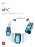
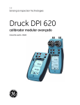
DPI 620 Genii
Advanced Modular Calibrator and HART®/
Foundation Fieldbus Communicator
Combines an advanced multi-function calibrator and HART /Foundation Fieldbus
communicator with world-class pressure measurement and generation.
.
A flexible modular system
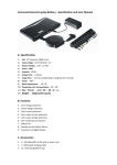
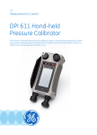
The Druck DPI 620 Genii Series - Advanced Modular Calibrator and HART /
Fieldbus Communicator comprises four system components to provide the
multi-functionality to perform duties formerly requiring a wide range of
different instruments. These system components are:
•
•
•
•
DPI 620G - Multi-function calibrator, HART/Fieldbus Communicator
PM 620 - Interchangeable pressure modules
MC 620G - Pressure module carrier
PV 62XG - Pressure generating stations
MC 620/G Pressure Module
Carrier. Securely attaches to
the DPI 620/G when
pressure measurement is
required.
PM620 Pressure Module
DPI 620/G Multifunction
Calibrator and Communicator
Features
• Multi-function capabilities: electrical,
frequency, temperature and pressure
• Complete HART communicator included
• Optional Foundation Fieldbus
communicator
• Modular re-rangeable and expandable
concept
• Individual components can be used as
stand-alone instruments
• Allows significant inventory reductions
• Simplifies training and improves
operator safety
• Reduces cost of ownership
Measure and source mA, mV, V, ohms, frequency, RTD’s
and thermocouples.
PM 620
Re-rangeable dual channel pressure measurement
from 25 mbar (10 inH2O) to 1000 bar (15000 psi)
PV 62X/G Pressure Station. The DPI
620/G securely attaches to the
pressure stations when pressure
generation and measurement is
required.
DPI 620/G
Re-rangeable pressure measurement and generation from 25 mbar (10 inH2O) to 1000 bar (15000 psi)
2
DPI 620 Genii (P/N DPI620G)
This ultra-compact electrical, frequency and temperature calibrator and HART communicator provides simultaneous measurement and
source capabilities for the setup, testing and calibration of most types of process instruments including transmitters, transducers, gauges/
indicators, switches, proximity detectors, counters, RTDs, thermocouples and valve positioners.
What’s new in Genii compared to the old DPI 620?
• Smart phone technology touch display and new UI (User Interface) supporting gestures and swipes for a flatter menu structure and
greater ease of use.
• Completely new digital platform and modems to support HART and Fieldbus applications.
• New DASHBOARD to quickly launch applications such as CALIBRATOR, HART and SETUP with new applications, including SCOPE for real
time signal diagnostics.
• TASK menu allows single touch configuration for common devices such as pressure and temperature transmitters, transducers, switches,
and valve positioners. User configured tasks can be added to the library.
• All first generation DPI 620 and the new Genii system components are fully interchangeable; e.g. pressure stations, pressure modules and
all accessories.
Standard Dashboard Applications:
Calibrator
• One touch selection of common tasks, e.g. P to I for a pressure transmitter
• Highest accuracy for measuring, sourcing and simulating electrical, frequency, temperature and pressure
• Simulate device inputs and measure outputs simultaneously (up to 6 active channels)
• Calculates errors between inputs/outputs
• Pressure system generates 100 bar/1,500 psi pneumatic and 1000 bar/15,000 psi hydraulic pressures.
• Interchangeable pressure modules from 25 mbar/1 inH2O to 1,000 bar/15,000 psi
Meter
• Easy to use Multi-meter
• Take measurements, test power supplies, check continuity
Scope
• Real time graphical analysis of pressure and electrical signals
• Advanced diagnostics and fault finding
HART Communicator
• View, change, clone and store device configurations
• Work off-line to create and change configurations
• Transfer device configurations to your PC
• Measure and source analogue variables without secondary calibration equipment
• No power during shutdown? Genii provides 24 V.
• Need a 230 ohm resistor? Just select from the menu.
• It’s easy to upgrade Genii with free of charge software and latest DD library.
3
Technical Specifications
DPI 620 Genii General Specifications
Display
Size: 110 mm (4.3 in) diagonal; 480 x 800 pixels
LCD: Colour display with touch-screen
Languages
English {Default}, Chinese, French, German, Italian, Portuguese, Russian, Spanish, Dutch, Japanese
Operating temperature -10° to 50°C (14° to 122°F)
Storage temperature
-20° to 70°C (-4° to 158°F)
Ingress Protection
IP54
Humidity
0 to 90% RH Non condensing
Shock / Vibration
BS EN 61010:2001; Def Stan 66-31, 8.4 cat III, 1 m Drop Tested
EMC
Electromagnetic compatibility: BS EN 61326-1:2006
Electrical safety
Electrical – BS EN 61010 : 2001
Pressure safety
Pressure Equipment Directive - Class: Sound Engineering Practice (SEP)
Approved
CE Marked
Size (L: W: H)
DPI 620 Genii only: 183 x114 x 42 mm (7.2 x 4.5 x 1.7 in) + MC 620/G: ≈ 265 x 114 x 64 mm ( 10.4 x 4.5 x 2.5 in)
+ PM 620: ≈ 265 x 114 x 93 mm (10.4 x 4.5 x 3.7 in)
Weight
DPI 620 Genii only: ≈ 575 g (1.3 lb) – battery included. MC 620G only: ≈ 640 g (1.4 lb). PM 620 only: ≈ 100 g (0.2 lb).
Power supply
Lithium-Polymer battery (GE Part number : IO620-Battery); Capacity: 5040 mAh (minimum), 5280 mAh (typical); Nominal voltage:
3.7 V. Charge temperature: 0° to 40°C (32° to 104°F) Discharge temperature: -20° to 60°C (-4° to 140°F).
Note: For best battery performance, keep the temperature less than 60°C (140°F). Charge/discharge cycles: > 500 > 70% capacity.
Duration
Measure functions (CH1): ≈ 12 hours continuous. Dual Function, mA measure (CH2): ≈ 7 hours (24 V Source at 12 mA)
Connectivity
USB Type A, USB Type Mini B, WiFi IEEE 802.11g, Bluetooth
4
Electrical Measurement and Source
NLH&R
±1°C (2°F) for 24 hrs
(note 1)
Measure mode
DC Voltage
Thermocouple
TC mode -10 to 100 mV
± 200 mV
± 2000 mV
± 20 V
± 30 V
AC Voltage1* 0 to 2000 mVAC
Current
Resistance
(True,
4 wire)
Resistance
(4 wire)
Frequency
Pressure
0 to 20 VAC
0 to 300 VAC
± 20 mA
± 55 mA
RTD
0 to 400 Ω
0 to 4000 Ω
RTD
0 to 400 Ω
0 to 4000 Ω
0 to 1000 Hz
1 kHz to 5 kHz**
0 to 999999 CPM
0 to 999999 CPH
Totalizing counter
Trigger level
25 mbar to 1000 bar
(0.35 psi to 15000 psi)
IDOS external module
USB port
%Rdg
+ %FS
Total Uncertainty
10° to 30°C (50° to 86°F)
for 1 year (note 3)
%Rdg
Please refer to Thermocouple specification table
0.0045
0.008
0.007
0.0045
0.004
0.01
0.004
0.003
0.0095
0.0025
0.002
0.0145
0.0035
0.0035
0.0145
0.125
0.125
0.2
0.1255
0.125
0.2
1
0.06
1.5
0.006
0.005
0.012
0.005
0.005
0.016
Please refer to RTD specification table
0.0055
0.001
0.009
0.0055
0.001
0.009
Please refer to RTD specification table
0.012
0.005
0.015
0.0115
0.0045
0.015
0.0003
0.0002
0.003
0.0003
0.0004
0.003
Refer to range table above for equivalent frequency
Refer to range table above for equivalent frequency
Maximum count 9999999
Automatic and adjustable 0 to 20 V
Please refer to PM 620 pressure range table
Additional error
-10° to 10°C (14° to 50°F)
30° to 50°C (86° to 122°F)
Resolution
%Rdg/°C
+ %FS/°C
0.01
0.005
0.005
0.002
0.004
0.15
0
0
0
0
0
0.005
0.0005
0.0005
0.0005
0.0005
0.0005
0.005
0.001
0.001
0.01
0.00001
0.0001
0.1
0.15
0.1
0.006
0.005
0.005
0.05
0
0
0.005
0.005
0.0005
0.0005
0.001
0.01
0.0001
0.0001
0.0012
0.0012
0
0
0.0005
0.0005
0.001
0.01
0.006
0.006
0.0002
0.0004
0
0
0.001
0.001
0.001
0.01
0.0001
0.00001
0.01
0.01
1
0.1
+ %FS
Display
reading
window
CH1
CH1
CH1
CH1
CH1
CH1
CH1
CH1
CH1
CH1
CH1
CH1
CH1
CH1
CH1
CH1
CH1
CH1
CH1
CH1
CH1
CH1
P1
Please refer to IDOS UPM datasheet. Cable P/N IO620-IDOS-USB+IO620-USB-PC required
Please refer to GE Measurement & Control for compatible devices
CH2
CH2
CH2
CH2
CH2
CH2
P2
IDOS
USB
Source mode
DC Voltage
Current
Resistance
Frequency
TC mode
TC mode -10 to 100 mV
0 to 200 mV
0 to 2000 mV
0 to 20 V
0 to 24 mA
0 to 24 mA (Internal loop
power)
24 V loop power
RTD
0 to 400 Ω (0.1mA)
0 to 400 Ω (0.5mA)
400 to 2000 Ω (0.05mA)
2k to 4 kΩ (0.05mA)
Please refer to Thermocouple specification table
0.009
0.008
0.014
0.0045
0.004
0.01
0.004
0.003
0.009*
0.006
0.0035
0.0145
0.01
0.004
0.015
0.01
0.004
0.015
0.01
0.005
0.005
0.0035
0.005
0.005
0
0
0
0
0
0
0.0005
0.0005
0.0005
0.0005
0.0005
0.0005
0.001
0.1
0.1
0.001
0.001
0.001
Selectable 24 V +/- 10% or 28V +/-10%
Please refer to RTD specification table
0.024
0.0035
0.03
0.004
0.0025
0.008
0.048
0.0035
0.06
0.048
0.0035
0.06
0.0075
0.003
0.006
0.0045
0
0
0
0
0.001
0.001
0.001
0.001
0.01
0.01
0.01
0.01
CH1
CH1
CH1
CH1
CH1
Maximum input current
0 to 1000 Hz
1kHz to 5 kHz**
Output waveform
0.1
0.001
CH1
CH1
Square wave peak output
0 to 99999 CPM
0-400 Ω 5 mA, 400-2000 Ω 1mA, 2000-4000 Ω 0.5 mA
0.0003
0.00023
0.003
0.00023
0.0003
0.000074
0.003
0.000074
Square, positive swing up to 20V (adjustable), negative swing -120mV (fixed)
Sine and Triangular, adjustable amplitude and offset within the limits -2.5 to +20 V
0 to 20V +/-20mV (6 mA maximum)
Please refer to range table above for equivalent frequency
1
CH1
0 to 99999 CPH
Totalizing counter
Please refer to range table above for equivalent frequency
Maximum count 1000000. Rate 1 to 50,000 pulses/sec
1
1
CH1
CH1
CH1
CH1
CH1
CH1
CH1
CH2
CH2
Notes:
1. Specification applies, 45 to 65Hz and between 10% and 100% of full scale.
2. Specification applies when calibration temperature is between 10 and 30°C
3. Maximum input current for ohms simulation: 0-400 _ 5 mA, 400-2000 _ 1mA, 2000-4000 _ 0.5 mA
Multiple parameter display capability
The display can be configured to show a maximum of 6 simultaneous reading windows as follows: CH1, CH2, P1, P2, IDOS, HART
5
“True Ohms” RTD Measure Mode (4-wire)
Type
Temperature
coefficient
Pt 50
3.85
Pt 100
3.85
Pt 100
3.92
Pt 200
3.85
Pt 500
3.85
Pt 1000 3.85
Cu 10
4.27
D 100
6.18
Ni 100
6.72
Ni 120
6.72
Temperature range
°C
°F
From
To
From
To
-200.00
0.00 -328.00
32.00
0.00 850.00
32.00 1562.00
-200.00
0.00 -328.00
32.00
0.00 850.00
32.00 1562.00
-200.00
0.00 -328.00
32.00
0.00 850.00
32.00 1562.00
-200.00
0.00 -328.00
32.00
0.00 260.00
32.00 500.00
260.00 850.00 500.00 1562.00
-200.00
-60.00 -328.00
-76.00
-60.00
0.00
-76.00
32.00
0.00 850.00
32.00 1562.00
-200.00 -150.00 -328.00 -238.00
-150.00
0.00 -238.00
32.00
0.00 850.00
32.00 1562.00
-200.00
0.00 -328.00
32.00
0.00 260.00
32.00 500.00
-200.00
0.00 -328.00
32.00
0.00 640.00
32.00 1184.00
-60.00
0.00
-76.00
32.00
0.00 250.00
32.00 482.00
-80.00
0.00 -112.00
32.00
0.00 270.00
32.00 518.00
270.00 320.00 518.00 608.00
Total Uncertainty
10° to 30°C (50° to 86°F) for 1
year
Rdg
Tos
%
°C
°F
0.012
0.05
0.09
0.012
0.05
0.09
0.012
0.04
0.07
0.012
0.04
0.07
0.012
0.04
0.07
0.012
0.04
0.07
0.01
0.03
0.051
0.01
0.03
0.051
0.015
0.077
0.14
0.01
0.026
0.044
0.015
0.05
0.086
0.012
0.05
0.086
0.009
0.024
0.04
0.011
0.036
0.061
0.012
0.036
0.061
0.00
0.14
0.25
0.00
0.17
0.3
0.01
0.035
0.06
0.012
0.035
0.06
0.00
0.026
0.047
0.00
0.03
0.055
0.00
0.022
0.04
0.00
0.028
0.05
0.00
0.057
0.1
Standard RTD Measure Mode (4-wire)
Type
Temperature
coefficient
Pt 50
3.85
Pt 100
3.85
Pt 100
3.92
Pt 200
3.85
Pt 500
3.85
Pt 1000 3.85
6
Cu 10
4.27
D 100
6.18
Ni 100
6.72
Ni 120
6.72
Temperature range
°C
°F
From
To
From
To
-200.00
0.00 -328.00
32.00
0.00 850.00
32.00 1562.00
-200.00
0.00 -328.00
32.00
0.00 850.00
32.00 1562.00
-200.00
0.00 -328.00
32.00
0.00 850.00
32.00 1562.00
-200.00
0.00 -328.00
32.00
0.00 260.00
32.00 500.00
260.00 850.00 500.00 1562.00
-200.00
-60.00 -328.00
-76.00
-60.00
0.00
-76.00
32.00
0.00 850.00
32.00 1562.00
-200.00 -150.00 -328.00 -238.00
-150.00
0.00 -238.00
32.00
0.00 850.00
32.00 1562.00
-200.00
0.00 -328.00
32.00
0.00 260.00
32.00 500.00
-200.00
0.00 -328.00
32.00
0.00 640.00
32.00 1184.00
-60.00
0.00
-76.00
32.00
0.00 250.00
32.00 482.00
-80.00
0.00 -112.00
32.00
0.00 270.00
32.00 518.00
270.00 320.00 518.00 608.00
Total Uncertainty
10° to 30°C (50° to 86°F) for 1
year
Rdg
Tos
%
°C
°F
0.021
0.16
0.28
0.024
0.16
0.28
0.017
0.1
0.175
0.0215 0.1
0.174
0.017
0.1
0.175
0.0215 0.1
0.174
0.017
0.069
0.12
0.018
0.069
0.12
0.033
0.33
0.6
0.0165 0.051
0.09
0.017
0.16
0.29
0.024
0.16
0.28
0.016
0.044
0.074
0.018
0.1
0.175
0.0215 0.1
0.174
0.035
0.66
1.18
0.01
0.66
1.18
0.019
0.1
0.174
0.02
0.1
0.174
0.00
0.071
0.13
0.002
0.071
0.13
0.00
0.06
0.11
0.00
0.06
0.11
0.00
0.2
0.36
RTD Simulate Mode (0.1mA min, 0-400Ω; 0.05mA min, 400-4000Ω)
Type
Temperature
coefficient
Pt 50
3.85
Pt 100
3.85
Pt 100
3.92
Pt 200
3.85
Pt 500
3.85
Pt 1000 3.85
Cu 10
4.27
D 100
6.18
Ni 100
6.72
Ni 120
6.72
Temperature range
°C
°F
From
To
From
To
-200.00
0.00 -328.00
32.00
0.00 850.00
32.00 1562.00
-200.00
0.00 -328.00
32.00
0.00 850.00
32.00 1562.00
-200.00
0.00 -328.00
32.00
0.00 850.00
32.00 1562.00
-200.00
0.00 -328.00
32.00
0.00 260.00
32.00 500.00
260.00 850.00 500.00 1562.00
-200.00
-60.00 -328.00
-76.00
-60.00
0.00
-76.00
32.00
0.00 850.00
32.00 1562.00
-200.00 -150.00 -328.00 -238.00
-150.00
0.00 -238.00
32.00
0.00 260.00
32.00 500.00
260.00 850.00 500.00 1562.00
-200.00
0.00 -328.00
32.00
0.00 260.00
32.00 500.00
-200.00
0.00 -328.00
32.00
0.00 640.00
32.00 1184.00
-60.00
0.00
-76.00
32.00
0.00 250.00
32.00 482.00
-80.00
0.00 -112.00
32.00
0.00 270.00
32.00 518.00
270.00 320.00 518.00 608.00
Total Uncertainty
10° to 30°C (50° to 86°F) for 1
year
Rdg
Tos
%
°C
°F
0.043
0.24
0.42
0.043
0.24
0.42
0.04
0.16
0.28
0.04
0.16
0.28
0.04
0.16
0.28
0.04
0.16
0.28
0.0345 0.12
0.21
0.0345 0.12
0.21
0.087
0.28
0.48
0.033
0.095
0.16
0.078
0.23
0.39
0.078
0.23
0.39
0.032
0.085
0.15
0.0675 0.19
0.32
0.0675 0.19
0.32
0.082
0.17
0.28
0.00
0.85
1.53
0.00
0.92
1.66
0.038
0.16
0.28
0.038
0.16
0.28
0.00
0.12
0.22
0.00
0.12
0.22
0.00
0.11
0.2
0.00
0.11
0.2
0.00
0.25
0.45
6
Note:
These figures relate to DPI 620 Genii uncertainties only.
For RTD Measure and Source functions the uncertainty
is given by:Urtd = T(°C) x %Rdg + Tos (°C)
or
Urtd = T(°F) x%Rdg + Tos (°F)
where T( ) is the measurement expressed in °C or °F.
Measurement resolution:
0.01 °C/F. Simulation resolution 0.1 °C/F
Excitation current:
Measure mode 0 to 400Ω 2.5mA, 400Ω to
4000Ω 0.5mA;
Simulate mode 0 to 400 Ω 5mA max, 0.4 to 2kΩ
1mA max and 2 to 4kΩ 0.5mA max.
Simulate mode pulsed excitation current minimum
duration 10 ms
7
Specifications relate to DPI 620 Genii uncertainties
only.
Measurement resolution 0.01 °C/F. Simulation
resolution 0.1 °C/F
Thermocouple Measurement and Simulation
Type
Standard
Cold Junction (CJ) Error (maximum) Range: 10 to 30°C (50 to 86°F) = 0.2°C (0.4°F)
Add 0.01°C (0.02°F) CJ Error/° ambient temperature
change for ranges: -10 to 10°C, 30 to 50°C
(14 to 50°F, 86 to 122°F) B
IEC 584
E
IEC 584
J
IEC 584
K
IEC 584
L
DIN 43710
N
IEC 584
R
IEC 584
S
IEC 584
T
IEC 584
U
DIN 43710
C
D
8
Temperature range
(range shows correct resolution)
°C
From
250.00
500.00
700.00
1200.00
-270.00
-200.00
-120.00
-210.00
-140.00
-270.00
-220.00
-160.00
-60.00
800.00
-200.00
-100.00
-270.00
-200.00
-40.00
-50.00
360.00
-50.00
70.00
320.00
660.00
-270.00
-230.00
-50.00
-200.00
-50.00
0.00
1600.00
2000.00
0.00
100.00
270.00
1200.00
To
500.00
700.00
1200.00
1820.00
-200.00
-120.00
1000.00
-140.00
1200.00
-220.00
-160.00
-60.00
800.00
1370.00
-100.00
900.00
-200.00
-40.00
1300.00
360.00
1760.00
70.00
320.00
660.00
1740.00
-230.00
-50.00
400.00
-50.00
600.00
1600.00
2000.00
2300.00
100.00
270.00
1200.00
1800.00
°F
From
482.00
932.00
1292.00
2192.00
-454.00
-328.00
-184.00
-346.00
-220.00
-454.00
-364.00
-256.00
-76.00
1472.00
-328.00
-148.00
-454.00
-328.00
-40.00
-58.00
680.00
-58.00
158.00
608.00
1220.00
-454.00
-382.00
-58.00
-328.00
-58.00
32.00
2912.00
3632.00
32.00
212.00
518.00
2192.00
To
932.00
1292.00
2192.00
3308.00
-328.00
-184.00
1832.00
-220.00
2192.00
-364.00
-256.00
-76.00
1472.00
2498.00
-148.00
1652.00
-328.00
-40.00
2372.00
680.00
3200.00
158.00
608.00
1220.00
3164.00
-382.00
-58.00
752.00
-58.00
1112.00
2912.00
3632.00
4172.00
212.00
518.00
2192.00
3272.00
Total Uncertainty
10° to 30°C (50° to 86°F)
for 1 year
°C
°F
4.00
2.00
1.50
1.00
2.00
0.50
0.25
0.50
0.30
4.00
1.00
0.50
0.30
0.50
0.40
0.25
7.00
1.00
0.40
3.00
1.00
3.00
1.50
1.10
1.00
3.00
1.00
0.30
0.60
0.30
0.80
1.00
1.40
1.10
0.80
0.60
0.80
7.20
3.60
2.70
1.80
3.60
0.90
0.45
0.90
0.54
7.20
1.80
0.90
0.54
0.90
0.72
0.45
12.60
1.80
0.72
5.40
1.80
5.40
2.70
1.98
1.80
5.40
1.80
0.54
1.08
0.54
1.44
1.80
2.52
1.98
1.44
1.08
1.44
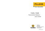
PM 620 Pressure
Modules
Features
• Fully interchangeable with no need for set-up or calibration
• Simple screw fit - hand tight no tools required
• Ranges from 25 mbar to 1000 bar (10 inH2O to 15000 psi)
• Accuracy from 0.005% FS
The PM 620 is the latest development in digital output sensor
technology incorporating a number of key innovations to allow
pressure re-ranging of compatible equipment. A simple screw fit
makes both the pressure and electrical connections without the
need for tools, sealing tape, cables or plugs and digital
characterisation allows interchangeability without set-up or
calibration.
MC 620/G Module Carrier
Features
• 2 independent pressure channels
• Simple to re-range
• Pressure protection
The MC 620/G module carrier attaches the head of the DPI 620/G to
provide two independent pressure measurement channels. These
can be fitted with any PM 620 pressure module from 25 mbar to
1000 bar (10 inH2O to 15000 psi). A simple screw fit means no tools
are required and ensures both a high integrity pressure seal and a
reliable digital interface. Even the pressure adapters are
interchangeable and only require a finger tight fit.
The carrier is designed for pressure safety and will automatically
seal if a module is not fitted or if the user attempts to remove it.
MC 620/G Specification
Maximum pressure
Pressure media
Pressure safety
Size and weight
400 bar (5800 psi) pneumatic
1000 bar (15000 psi) hydraulic
Compatible with stainless steel and nitrile
seals
Pressure equipment directive class SEP
80 mm x 100 mm x 110 mm, 640 g
9
PM 620 Specification
Maximum intermittent pressure
Maximum working pressure
Sealing
2 x FS
110% FS
IP 65 (protected against dust and
jets of water)
-10 to 50°C (14 to 122°F)
-20 to 70°C (-4 to 158°F)
0 to 90% RH non condensing
BS EN 61010:2001; Def stan 66-31,
8.4 cat III), 1 m Drop Tested
BS EN 61326-1:2006
BS EN 61010:2001
Pressure equipment directive class
SEP
CE marked
L. 56 mm, Dia. 44 mm,
106 g maximum
Operating temperature
Storage temperature
Humidity
Shock and vibration
EMC
Electrical safety
Pressure safety
Approval
Size and weight
Gauge Ranges (referenced to atmosphere)
Media
bar
±0.025
±0.07
±0.2
±0.35
±0.7
±1
-1 to 2
-1 to 3.5
-1 to 7
-1 to 10
-1 to 20
0 to 35
0 to 70
0 to 100
0 to 135
0 to 200
psi
±10 inH2O
±1
±3
±5
±10
-14.5 to 15
-14.5 to 30
-14.5 to 50
-14.5 to 100
-14.5 to 150
-14.5 to 300
0 to 500
0 to 1000
0 to 1500
0 to 2000
0 to 3000
NLH&R
20°C ±2°C
(68°F ± 4°F)
24 hr
NLH&R
0° to 50°C
(32° to 122°F)
24 hr
Gauge
%FS
0.090
0.025
0.020
0.020
0.015
0.015
0.015
0.010
0.010
0.005
0.005
0.005
0.005
0.005
0.005
0.005
Gauge
%FS
0.090
0.030
0.027
0.025
0.020
0.020
0.020
0.020
0.020
0.020
0.020
0.020
0.020
0.020
0.020
0.020
1
1
1
2
2
2
2
2
2
2
2
2
2
2
2
2
Total
uncertainty
0° to 50°C
(32° to 122°F)
for 1 year
Gauge
%FS
0.100
0.047
0.045
0.044
0.041
0.041
0.025
0.025
0.025
0.025
0.025
0.025
0.025
0.025
0.025
0.025
NLH&R Non-linearity, hysteresis and repeatability
Compatible with non-corrosive gas/fluid
Compatible with stainless steel
*
The reading can be referenced to ambient air
pressure via a software feature of the DPI 620
Genii, allowing the same module to be
switched between absolute and sealed gauge
measurement
DPI 620 Genii pressure resolution: adjustable 4 to 7
digits. Uncertainty confidence level 95% (K=2)
Absolute Ranges (referenced to vacuum)
Media
bar
0 to 0.35
0 to 1.2
0 to 2
0 to 3.5
0 to 7
0 to 10
0 to 20
0 to 35
0 to 70
0 to 100
0 to 135
0 to 200
0 to 350
0 to 700
0 to 1000
10
psi
0 to 5
0 to 35 inHg
0 to 30
0 to 50
0 to 100
0 to 150
0 to 300
0 to 500
0 to 1000
0 to 1500
0 to 2000
0 to 3000
0 to 5000
0 to 10000
0 to 15000
2
2
2
2
2
2
2
2
2
2
2
2
2
2
2
NLH&R
20°C ±2°C
(68°F ± 4°F)
24 hr
Absolute
%FS
0.030
0.020
0.015
0.015
0.015
0.015
0.015
0.015
0.015
0.015
0.015
0.015
0.015
0.015
0.015
NLH&R
20°C ±2°C
(68°F ± 4°F)
24 hr
*Sealed
Gauge
%FS
0.005
0.005
0.005
0.005
0.005
0.005
0.005
0.005
0.005
0.005
NLH&R
0° to 50°C
(32° to 122°F)
24 hr
Absolute
%FS
0.050
0.036
0.036
0.036
0.036
0.030
0.030
0.030
0.030
0.030
0.030
0.030
0.033
0.033
0.033
NLH&R
0° to 50°C
(32° to 122°F)
24 hr
*Sealed
Gauge
%FS
0.020
0.020
0.020
0.020
0.020
0.020
0.020
0.020
0.020
0.020
Total uncertainty
0° to 50°C
(32° to 122°F)
for 1 year
Absolute
*Sealed
Gauge
*%FS
%FS
0.080
0.070
0.052
0.050
0.050
0.047
0.025
0.047
0.025
0.047
0.025
0.047
0.025
0.046
0.025
0.046
0.025
0.046
0.025
0.049
0.025
0.049
0.025
0.049
0.025
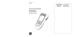
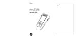
The PV 621/G, 622/G and
623/G Pressure Stations
Features
• A uniquely capable, re-rangeable and self contained pressure test
system
• Advanced pressure generation
- 95% vacuum to 20 bar (300 psi) pneumatic
- 95% vacuum to 100 bar (1500 psi) pneumatic
PV 621/G, 622/G and 623/G Specification
Maximum pressure
PV 621/G 20 bar (300 psi) pneumatic
PV 622/G 100 bar (1500 psi) pneumatic
PV 623/G 1000 bar (15000 psi) hydraulic
Pressure media
PV 621/G and PV 622/G non-corrosive gases,
PV 623/G de-mineralized water or mineral oil
(ISO viscosity grade < 22)
Operating temperature -10° to 50°C (14° to 122°F)
For water +4 to +50°C (39 to 122°F)
Storage temperature
-20 to 70°C (-4 to 158°F) (must be empty of water)
Shock and vibration
BS EN 61010:2001; Def stan 66-31, 8.4 cat III,
1 m drop tested
Pressure safety
Pressure equipment directive class SEP
Size and weight
450 mm x 280 mm x 235 mm,
PV 621/G 2.65 kg, PV 622/G 3.30 kg, PV 623/G
3.75 kg
- 0 to 1000 bar (15000 psi) hydraulic
• Stand alone replacements for hand pumps
• Bench top use as comparators
There are three pressure generation stations: the PV 621/G, a
pneumatic pressure generator for pressures 95% vacuum to
20 bar (300 psi); the PV 622/G, a pneumatic pressure generator for
pressures 95% vacuum to 100 bar (1500 psi); and the PV 623/G, a
hydraulic pressure generator for pressures up to 1000 bar
(15000 psi). Each pressure station is designed for stand-alone
operation as a pressure generator and can replace conventional
hand pumps to provide greater efficiency and ease of use. They can
also be used on the workbench as comparators.
Combining any of the pressure stations with a PM 620 pressure
module and the DPI 620/G calibrator creates a uniquely capable,
self-contained pressure calibrator.
PV 622G
11
Ordering Information
All DPI 620/DPI620G series products are compatible with each other.
For the intrinsically safe DPI620IS and compatible accessories,
please refer to the DPI620IS datasheet.
Please order the following model numbers and part numbers as
separate line items.
Model DPI 620G
Genii advanced modular calibrator and HART communicator
Model DPI 620G FF
Genii advanced modular calibrator and HART/Fieldbus
communicator
The DPI 620/G are supplied with a rechargeable lithium polymer
battery P/N IO620-BATTERY, universal mains adaptor/charger P/N
IO620-PSU, IO620-AC 300 VAC true rms measurement probe, test
leads, calibration certificate, and quick reference guide.
Model MC620G
Genii pressure module carrier
Supplied with G 1/8 female and 1/8 NPT female adaptors (2 of
each).
Model PM 620 “pressure range” and “type”
Pressure module. Supplied with calibration certificate.
e.g., PM 620 20 bar (300 psi) gauge
System carrying case (P/N IO620-CASE-2)
A protective carrying case for system components including the DPI
620/G, MC 620/G, PM 620 modules, test leads, hose and adaptors.
Spare/replacement lithium polymer rechargeable
battery (P/N IO620-BATTERY)
Spare/replacement battery for the DPI 620/G. P/N IO620-BATTERY is
supplied as standard with all new DPI 620/G.
Battery charging station (P/N IO620-CHARGER)
This external battery charging station allows a spare battery to be
charged independently of the DPI 620/G for minimum instrument
down time. Power is provided by the standard mains adaptor (P/N
I0620-PSU). A complete charge cycle takes approximately 6.5 hours.
Simultaneously, the DPI 620/G can be connected via a USB cable to
provide a top-up charge (full charge in 13 hours).
Spare/replacement mains adaptor
(P/N IO620-PSU)
A spare/replacement universal mains adaptor for use with DPI 620/G
and P/N IO620-CHARGER. Input voltage 100 to 240 VAC 50/60 Hz.
Mains socket adaptors are provided. P/N IO620-PSU is supplied as
standard with all new DPI 620/G.
USB cable (P/N IO620-USB-PC)
Model PV621G
Pneumatic pressure station 20 bar (300 psi)
Model PV622G
Pneumatic pressure station 100 bar (1500 psi)
Model PV623G
Pressure station 1000 bar (15000 psi)
Connects the DPI 620/G to a PC.
The PV 621/G, 622/G and 623/G are supplied with G1/8 female and
1/8 NPT female adaptors, carry strap, and quick reference guide. In
addition, the PV 623/G includes a plastic bottle for hydraulic fluid.
USB to RS 232 cable (P/N IO620-USB-RS232)
DPI 620/G
Accessories
Replacement AC voltage measurement probe
(P/N IO620-AC)
Attaches to the DPI 620/G 30 V sockets to provide 300 VAC true rms
measurement. P/N IO620-AC is supplied as standard with all new
DPI 620/G.
Carrying case (P/N IO620-CASE-1)
A protective carrying case with belt loop, shoulder strap and large
pocket for test leads and accessories.
12
IDOS to USB converter (P/N IO620-IDOS-USB)
Allows connection of an IDOS universal pressure module to the
DPI 620/G. P/N IO620-USB-PC is also required to connect the
converter to the DPI 620/G USB port.
Connects the DPI 620/G to an RS 232 interface.
PV 621/G, 622/G, 623/G
and MC 620/G
Accessories
Dirt moisture trap
Prevents contamination of the PV 621/G and 622/G pneumatic
systems and cross contamination from one device under test to
another. The IDT connects directly to the PV 621/G and 622/G
pressure port and replicates the quick fit connection for
compatibility with the hose and adaptor kits
P/N IO620-IDT621: Maximum working pressure 20 bar (300 psi)
P/N IO620-IDT622: Maximum working pressure 100 bar (1500 psi)
Pneumatic hose kit
A high pressure pneumatic hose rated to 400 bar (5800 psi).
Tool less quick fit to the PV 621/G, PV 622/G and MC 620/G pressure
ports. Terminated with a quick fit connector compatible with the
test point adaptors supplied with the PV 62X/G, MC 620/G and the
adaptor sets.
P/N IO620-HOSE-P1: 1 metre pneumatic hose kit
P/N IO620-HOSE-P2: 2 metre pneumatic hose kit
Hydraulic hose kit
Pressure relief valve
A high pressure hydraulic hose rated to 1000 bar (15000 psi).
Tool less quick fit to the PV 623/G and MC 620/G pressure ports.
Terminated with a quick fit connector compatible with the test point
adaptors supplied with the PV 62X/G, MC 620/G and the adaptor
sets.
P/N IO620-HOSE-H1: 1 metre hydraulic hose kit
P/N IO620-HOSE-H2: 2 metre hydraulic hose kit
When fitted to a PV 62X/G pressure station protects the PM 620
pressure module and the device under test from overpressure.
Pressure adaptor set
Relief Valve Table
Part number
For use with
IO620-PRV-P1
IO620-PRV-P2
IO620-PRV-P3
IO620-PRV-P4
IO620-PRV-P5
IO620-PRV-P6
IO620-PRV-P7
IO620-PRV-P8
IO620-PRV-H1
IO620-PRV-H2
IO620-PRV-H3
IO620-PRV-H4
IO620-PRV-H5
PV 621G PV 622G
PV 621G PV 622G
PV 621G PV 622G
PV 622G
PV 622G
PV 621G PV 622G
PV 621G PV 622G
PV 621G PV 622G
PV 623G
PV 623G
PV 623G
PV 623G
PV 623G
Factory
setting
bar psi
1
15
5
100
30
435
60
870
100 1500
3
45
12
170
18
260
50
725
200 3000
400 6000
700 10000
1000 15000
Adjustable range
bar
0.2 to 1
3 to 7
16 to 32
30 to 60
60 to 100
1.1 to 3
6.1 to 12
12.1 to 18
10 to 50
50 to 200
200 to 400
300 to 700
600 to 1000
psi
3 to 15
45 to 100
230 to 460
435 to 870
870 to 1500
16 to 45
90 to 170
175 to 260
145 to 725
725 to 2900
2900 to 5800
4350 to 10000
8700 to 15000
Pressure station carrying case
(P/N IO620-CASE-3)
A set of test point adaptors to connect the tool less quick fit PV
62X/G, MC 620/G and the extension hoses to the device under test.
P/N IO620-BSP: G1/8 male and G¼ male, G¼ female, G3/8 female
and G½ female
P/N IO620-NPT: 1/8” male and ¼”male, ¼” female, 3/8” female, and
½” female
P/N IO620-MET: 14 mm and 20 mm female
Comparator adaptor (P/N IO620-COMP)
Allows the PV 62X/G pressure station to be used as a comparator.
The adaptor connects to the stations pressure port and provides
two outlet ports for making gauge comparisons. Compatible
with the test point adaptors supplied with the PV 62X/G and the
adaptor sets.
Blanking plug (P/N IO620-BLANK)
A protective carrying case with shoulder strap and large pocket for
accessories. Also accommodates the assembled system including
the DPI 620/G and PM 620.
Allows the PV 621/G and 622/G to be used as pressure generators
independently of the DPI 620/G and PM 620 by blanking the PV
62X/G pressure module port. Not required for the PV 623/G as the
port is self-sealing.
Modular system transit case (P/N IO620-CASE-4)
DPI 104 Gauge adaptor (P/N IO620-104 ADAPT)
A rigid transit case with wheels and an extendable handle.
Accommodates two PV 62X/G pressure stations, DPI 620/G, MC
620/G and PM 620 modules, with ample storage space for
accessories. Size: 736 mm x 554 mm x 267 mm. Weight: 8,5 kg
empty
Allows a DPI 104 digital pressure gauge to be connected to the PV
62X/G pressure module port in place of DPI 620/G and PM 620 to
provide a simple low cost pressure calibrator.
13
GE
Sensing & Inspection Technologies
A1.1
PV 621: Pneumatic pressure station (Figure A2.1)
-950 mbar to 20 bar (-13.5 to 300 psi)
Druck PV 62x
pneumatic/hydraulic pressure stations
PV 622: Pneumatic pressure station (Figure A2.2)
-950 mbar to 100 bar (-13.5 to 1500 psi)
PV 623: Hydraulic pressure station (Figure A2.3)
0 to 1000 bar (0 to 15000 psi)
A1.2
safety and quick reference guide - K0458
PV 62x + DPI 620 + PM 620
Recommended pressure modules (PM 620) *
(Figure B1/B2)
PV 621 models
25 mbar to 20 bar
(0.36 to 300 psi)
PV 622 models
25 mbar to 100 bar
(0.36 to 1500 psi)
PV 623 models
70 to 1000 bar
(1000 to 15000 psi)
* Caution: To prevent damage to the PM 620 module, only
use it within the specified pressure limit on the label.
A1.3
PV 62x pressure relief valves (PRV)
(Recommended options)
Parts: IO620-PRV-P1 to P5 (Pneumatic)
PV 621 models
1 to 30 bar
(14.5 to 435 psi)
PV 622 models
1 to 100 bar
(14.5 to 1500 psi)
Parts: IO620-PRV-H1 to H5 (Hydraulic)
PV 623 models
Note:
50 to 1000 bar
(725 to 15000 psi)
= See figure, table, or section.
© 2008 General Electric Company. All rights reserved.
Trademarks
All product names are trademarks of their respective companies.
Customer service
PV 621
A2.1
3
1
PV 623
A2.3
3
1
4
2
PV 622
A2.2
3
1
4
2
A4
PV 623:
A5
S3.1
PV 622, PV 623
1
4
2
Visit our web site: www.gesensing.com
2
A3
5
1
6
6
7
7
6
2
3
B1
PM 620:
7
1
8
9
10
9
4
5
+
11
11
12
12
S3.3
PV 62x + DPI 620 + PM 620
B2
4
PV 62x
A3
3
1
1
2
3
2
2
K0458 Issue 1
2
2
A1.2
a
Quick Reference
WARNING: Before you use this instrument, read and understand the “Safety”
section. It is dangerous to ignore the specified warnings.
S1 PV 621 models: Start operations
S1.1
A2.1 (Front cover)
Release the pressure/Attach the device under test
2
1
S1.2
Step
Procedure
1.
Release the pressure.
2.
Use the applicable adaptor to
attach the device; figure A3.
4
2
Vacuum OR pressure operation
1
2
3
4
5
+
Step
Procedure (Vacuum)
1.
Set to vacuum operation (-).
2.
3.
Turn the volume adjuster to
mid-range or fully clockwise.
Seal the system.
4.
Set the vacuum with the pump.
5.
Adjust the vacuum
(+ decrease; - increase).
Step
Procedure (Pressure)
11
1.
Set to pressure operation (+).
8
2.
4
3.
Turn the volume adjuster to
mid-range.
Seal the system.
12
4.
Set the pressure with the pump.
5.
Adjust the pressure
(+ increase; - decrease).
8
S2 PV 622 models: Start operations
S2.1
-
11
8
4
12
8
A2.2 (Front cover)
Release the pressure/Attach the device under test
1
2
b
a
[EN] English - K0458 Issue 1
Step
1.
2.
Procedure
Release the pressure: Open the
refill valve (1 turn) then fully open
the pressure release valve.
Use the applicable adaptor to
attach the device; figure A3.
5
4
2
Quick Reference 1
S2.2
Vacuum OR pressure operation
1
4
2
3
5
Step
6
-
+
1
2
3
1.
Set to vacuum operation (-).
11
2.
Open the refill valve (1 turn).
5
3.
9
4.
Wind the volume adjuster to
mid-range or fully clockwise.
Seal the system.
5.
Set the vacuum with the pump.
6.
Adjust the vacuum
(+ decrease; - increase).
Step
Procedure (Pressure)
1.
Set to pressure operation (+).
2.
Wind the volume adjuster to
mid-range.
Seal the system.
3.
4
5
4.
-
+
6
7
5.
6.
+
7.
8.
2 Quick Reference
Procedure (Vacuum)
4
12
9
11
9
4
Use the pump to set a pressure up 12
to ≈ 20 bar (300 psi).
Open the refill valve (1 turn). You
5
now have full control to increase (+)
9
or decrease (-) the pressure with
the volume adjuster.
If you increase pressure and get to
5
the limit of travel, close the refill
valve and wind the volume adjuster 9
fully counterclockwise. There is no
change in pressure.
Refill the pressure mechanism with 12
the pump (≈ 15 cycles) and wind
the volume adjuster clockwise until 9
the pressure starts to increase.
Continue to do steps 5 to 7 until you get
the necessary pressure.
K0458 Issue 1 - [EN] English
S3 PV 623 models: Start operations
S3.1
A2.3 (Front cover)
Fill the reservoir. Figure A4 (front cover). The first time you want to use the
hydraulic pressure station, use this procedure to fill the reservoir:
Step
Procedure
Step
Use the applicable adaptor to
attach the device; figure A3.
Remove the hydraulic pressure
release valve.
Use the refill bottle to add the
necessary hydraulic fluid but
leave a small air gap.
1.
2.
3.
S3.2
To remove air from the pressure
9
mechanism, wind the volume
adjuster through one full cycle
(counterclockwise then clockwise).
Seal the system and continue
4
with the normal pressure
operation.
4.
2
4
5.
4
Procedure
Release the pressure/Attach the device under test
2
1
Step
Procedure
Release the pressure: Open the
refill valve (1 turn) then fully open
the pressure release valve.
1.
Use the applicable adaptor to
attach the device; figure A3.
2.
10
4
2
Note: Fill the reservoir before you attach the device. See figure A4 (front cover).
S3.3
Hydraulic pressure operation
1
2
3
4
+
Step
+
Procedure
Step
1.
Seal the system.
2.
Close the refill valve and then
10
wind the volume adjuster fully
clockwise and counterclockwise 9
until the pressure starts to
increase.
The counterclockwise operation refills
the pressure mechanism without a
change in pressure.
[EN] English - K0458 Issue 1
4
3.
4.
5.
-
Procedure
Open the refill valve (1 turn). You
now have full control to increase 10
(+) or decrease (-) the pressure
9
with the volume adjuster.
If you increase pressure and get
10
to the limit of travel, close the
refill valve again and wind the
9
volume adjuster fully
counterclockwise.
Continue to do steps 2 to 4 until you
get the necessary pressure.
Quick Reference 3
1
Overview
PV 621
There are three pressure stations in the PV 62x series:
•
PV 621: -950 mbar to 20 bar (-13.5 to 300 psi) version
PV 622: -950 mbar to 100 bar (-13.5 to 1500 psi) version
PV 622
PV 623
two pneumatic pressure stations to give you accurate and
controlled pressure and vacuum conditions:
•
one hydraulic pressure station to give you accurate and
controlled hydraulic pressure conditions:
PV 623: 0 to 1000 bar (15000 psi)
1.1 Other module
options
Pressure calibrator
DPI 620
PM 620
4 Overview
The pressure stations are part of a set of hand-held modules
that you can quickly put together to include a wide range of
calibrator functions.
DPI 620 Pressure calibrator: You can use the pressure
stations on their own or you can attach the DPI 620 calibrator
and a PM 620 module to make a fully integrated pressure
calibrator instrument.
Advanced modular calibrator, DPI 620: Optional item. This is
a battery-powered instrument for electrical measure and source
operations and HART® communications. It also supplies the
power and user interface functions for all the add-on modules.
You can use the touch-screen to display up to six different
parameters. Refer to user manual - K0449.
Pressure modules, PM 620: Optional item. These modules
attach to a pressure station (PV 62x) to give the DPI 620
calibrator the necessary pressure measurement functionality.
They are fully interchangeable “plug and play” modules with no
initial set-up or user calibration.
K0458 Issue 1 - [EN] English
2
3
Standard
equipment
Safety
These items are part of the standard equipment with a PV 62x
pressure station:
•
Removable pressure adaptors (G1/4 and 1/8 NPT)
•
PV 623 models only: Refill bottle for hydraulic fluid
•
Safety and quick reference guide
•
CD with the user manual
Before you use the instrument, make sure that you read and
understand all the related data. This includes: the applicable
local safety procedures, the user manual (K0457), and the
instructions for the accessories/options/equipment you are
using it with.
General
warnings
Pressure
warnings
WARNING
•
It is dangerous to ignore the specified limits for the
instrument or to use the instrument when it is not in its
normal condition. Use the applicable protection and
obey all safety precautions.
•
Do not use the instrument in locations with explosive
gas, vapour or dust. There is a risk of an explosion.
•
It is dangerous to attach an external source of pressure
to a PV 62x series pressure station. Use only the
internal mechanisms to set and control the pressure in
the pressure station.
•
Some liquid and gas mixtures are dangerous. This
includes mixtures that occur because of
contamination. Make sure that the equipment is safe to
use with the necessary media.
•
To prevent a dangerous release of pressure, isolate and
bleed the system before you disconnect a pressure
connection.
•
To prevent a dangerous release of pressure, make sure
that all the related pipes, hoses and equipment have
the correct pressure rating, are safe to use and are
correctly attached.
Continued
[EN] English - K0458 Issue 1
Standard equipment 5
Electrical
warnings
Cautions
If you use the DPI 620 calibrator with your pressure station,
these warnings are also applicable:
•
To prevent electrical shocks or damage to the
instrument, do not connect more than 30V between the
terminals, or between the terminals and the ground
(earth).
•
This instrument uses a Lithium-Polymer (Li-Polymer)
battery pack. To prevent an explosion or fire, do not
short circuit, do not disassemble, keep it safe from
damage.
•
To prevent an explosion or fire, use only the GE
specified battery, power supply and battery charger.
To prevent damage to the PM 620 module, only use it
within the specified pressure limit on the label.
To prevent damage to the instrument, do not let dirt get
into the pressure mechanism. Clean the equipment
before you attach it.
Before you start an operation or procedure in this publication,
make sure that you have the necessary skills (if necessary, with
qualifications from an approved training establishment). Follow
good engineering practice at all times.
Marks and
symbols on the
instrument
Complies with European
Union directives
Read the manual
Warning - refer to the
manual
PRV Pressure relief valve
Do not dispose of this product as household waste.
Refer to “Maintenance” (Section 6).
More marks and symbols are specified in the user manual
(K0457 - Druck PV 62x pneumatic/hydraulic pressure stations)
6 Safety
K0458 Issue 1 - [EN] English
4
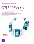
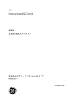
Parts
Refer to the figures on the front cover (A2, B1).
4.1 Key to figure A2 (PV 62x pressure stations)
A2
1.
Optional accessory: Pressure connection for a pressure relief
valve (PRV); see table A1.3 (front cover). A blanking plug is
standard.
2.
Test port: Pressure connection (G1/8 or 1/8NPT) to attach the
device under test; see figure A3 (front cover).
3.
Pressure and electrical connections for a PM 620 module.
PV 621/PV 622 models: Seal the pressure connection with a
blanking plug (Part: IO620-BLANK) or a PM 620 module.
PV 623 models only: The pressure connection seals itself.
4.
Pneumatic pressure release valve (PV 621/PV 622 models) or
hydraulic pressure release valve (PV 623 models) to release
pressure in the system.
On PV 623 models, it also gives access to the hydraulic fluid
reservoir; see figure A4 (front cover).
5.
PV 622 models only: Pneumatic refill valve. Close it to seal off
the device pressure and refill the pressure mechanism (refer to
“Quick Reference”, S2).
6.
Moulded compartment for the DPI 620 calibrator with electrical
connections and a mechanism to hold it in position.
7.
Push-button mechanism to release the DPI 620 calibrator.
8.
PV 621 models only: Pneumatic volume adjuster
9.
PV 622/PV 623 models only: Volume adjuster wheel with
fold-in handle.
10. PV 623 models only: Hydraulic refill valve. Close it to seal off
the device pressure and refill the pressure mechanism with
fluid (refer to “Quick Reference”, S3).
11. PV 621/PV 622 models only: Pressure/vacuum selector to set
the pump operation: pressure (+), vacuum (-).
12. PV 621/PV 622 models only: Pump mechanism
[EN] English - K0458 Issue 1
Parts 7
4.2 Key to figure B1 (PM 620 module) - Optional item
B1
13.
Pressure module (PM 620) with a pressure connection,
reference port (a) and a label. The label includes:
Pressure limit. Example: 20 bar g (g: gauge; a: absolute);
serial number (S/N); manufacturer: name, address, website
5
Installation
Before you start:
•
Read and understand the “Safety” section.
•
Do not use damaged equipment.
Note: Use only original parts supplied by the manufacturer.
5.1 External pressure
connections
See figure A3 (front cover). Use an applicable method to seal
the external pressure connections, and then tighten to the
applicable torque. Maximum torque:
1/8 NPT: 35 Nm (26 lbf.ft)
G1/8: 25 Nm (18.4 lbf.ft)
5.2 Calibrator
assembly
B2
8 Installation
Optional item (DPI 620/PM 620). See figure B2 (front cover).
Note: To use the DPI 620 calibrator, read the user manuals:
K0449 (Druck DPI 620 Advanced modular calibrator) and
K0457 (Druck PV 62x pneumatic/hydraulic pressure stations).
Step
Procedure
1.
Lower the calibrator into the moulded compartment.
2.
Press on the bottom end of the calibrator until it latches in
position.
3.
Attach a pressure module with the correct range and type.
4.
Tighten it until it is hand tight only.
K0458 Issue 1 - [EN] English
6
Maintenance
Clean the case with a moist, lint-free cloth and a weak
detergent. Do not use solvents or abrasive materials.
Return the instrument to the manufacturer or an approved
service agent for all repairs.
Do not dispose of this product as household waste. Use an
approved organisation that collects and/or recycles waste
electrical and electronic equipment. For more information,
contact one of these:
7
•
our customer service department:
(Contact us at www.gesensing.com)
•
your local government office.
Specification
Table 1: General specification
Operating temperature -10 to 50°C (14 to 122°F)
Note: PV 623 models only. If the temperature is less than 4°C
(39°F), the instrument must be fully drained and dry.
Storage
temperature
-20 to 70 °C (-4 to 158 °F)
Humidity
0 to 90% relative humidity (RH) non-condensing
Shock/Vibration
Def Stan 66-31, 8.4 cat III
EMC
Electromagnetic compatibility: BS EN 61326-1:2006
Electrical safety
Electrical - BS EN 61010:2001
Pressure safety
Pressure Equipment Directive - Class: Sound Engineering
Practice (SEP)
Approved
CE Marked
Note: PV 623 models only. If the temperature is less than 4°C
(39°F), the instrument must be fully drained and dry.
Hydraulic fluid (PV 623 Reservoir capacity: 100 cm3 (6.1 in3)
models only)
Fluid type: Demineralised water or a mineral oil (ISO viscosity
grade ≤ 22)
Power supply
9
Maintenance/Specification
None. If you attach a DPI 620 calibrator to make a pressure
calibrator, all the power comes from the DPI 620 calibrator.
Refer to user manual K0449 - Druck DPI 620 Advanced
modular calibrator.
K0458 Issue 1 - [EN] English
[EN] English - K0458 Issue 1
10
11
K0458 Issue 1 - [EN] English
[EN] English - K0458 Issue 1
12