1
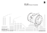
BULLETIN A-30-666
SERIES 666 RANGEABLE DIFFERENTIAL PRESSURE TRANSMITTER
Specifications– Installation and Operating Instructions
3/16 [4.76] DIA. MOUNTING HOLE
2-11/16 [68.26]
3/4 [19.05]
1-11/32 [34.13]
5-19/32
[142.08]
6-13/64 [157.56]
Ø5/8 [15.88]
1-9/32 [32.54]
3/16 [4.76] OD PRESSURE FITTING
HIGH LOW
2-3/8 [60.33]
1-3/16 [30.16]
15/16 [23.81]
Description
Versatility is the key with our Series 666 Rangeable
Differential Pressure Transmitter. Up to 6 field selectable
pressure ranges are available in a single model. Four
dipswitches located inside the transmitter case make
calibration simple and easy. Glass Filled Polycarbonate
housing provides environmental protection per NEMA 4
(IP65). Units can withstand overpressure to 10 psig. Low
pressure ranges and ±1% full scale accuracy make
these transmitters ideal for HVAC and energy management applications.
Installation
Pressure Fitting
Two (2) 3/16 O.D. barbed pressure fittings are supplied
for pressure connection with 1/4 push-on tubing. Both
the positive (high) pressure port and the reference (low)
pressure port are located on the bottom of the unit,
labeled High and Low respectively. For best results
(shortest response times), 3/16 I.D. tubing is suggested
for tubing lengths up to 100 feet long, 1/4 I.D. for tubing
lengths up to 300 feet, and 3/8 I.D. for tubing lengths up
to 900 feet.
Electrical Connections
Wiring is through a PG9 cable strain relief. Wiring terminations are identified on the circuit board below the
terminal strip. To access the terminal strip, remove the
cover by using the screws on the top of the case.
The Series 666 Current transmitter is a loop-powered 4
to 20 mA current output unit. (See Figure 1). The current
flows into +EXC. terminal and returns back to the power
supply through the -EXC. terminal. The power supply
must be a DC voltage source with a voltage range
between 9 and 30 VDC measured between terminal
+EXC. and -EXC.
DWYER INSTRUMENTS, INC.
P.O. BOX 373 • MICHIGAN CITY, INDIANA 46361, ,U.S.A.
1-47/64
[44.05]
51/64 [20.24]
PHYSICAL DATA
Service: Air and nonconductive gases.
Accuracy: ±1% of full
scale (RSS) (includes nonlinearity, hysteresis, and
non-repeatability).
Output: 4 to 20 mA, 2wire.
Loop Resistance: 0-500
ohms.
Supply Voltage: 9-30
VDC.
Maximum Pressure: 10
psig (0.7 kg/cm2).
Compensated Range: 40
to 150°F (5 to 65°C).
Thermal Effects: 0.033%
FS/°F (0.06% FS/°C)
includes zero and span.
Temperature Limits:
Operating: 0 to 150°F (-18
to 65°C), Storage: -65 to
180°F (-54 to 82°C).
Housing: Glass Filled
Polycarbonate case,
NEMA 4 (IP65).
Mounting: 2 mounting
tabs with .18 dia. holes.
Electrical Connection:
Screw terminal strip with
PG-9 cable strain relief.
Pressure Connection:
3
/16 O.D. barbed brass
pressure fitting for 4 I.D.
tubing.
Weight: 16.4 oz (465 g).
SERIES 666 TRANSMITTER MODELS & RANGES
Model
Number
Ranges,
Inches W.C.
Model
Number
666-1
0 to 0.1, 0 to ±0.05
666-3
666-2
0 to 0.25, 0 to 0.5,
0 to 1.0, 0 to 0.125,
0 to ±0.25, 0 to ±0.5
666-4
Ranges,
Inches W.C.
0 to 1.25, 0 to 2.5,
0 to 5, 0 to ±0.625,
0 to ±1.25, 0 to ±2.5.
0 to 7.5, 0 to 15,
0 to 30, 0 to ±3.75,
0 to ±7.5, 0 to ±15.
* Also available with optional LCD display. Consult factory for additional information.
Phone: 219/879-8000
Fax: 219/872-9057
Lit-By Fax: 888/891-4963
www.dwyer-inst.com
e-mail: [email protected]
The unit is calibrated at the factory using a 250 ohm load
at 24 VDC.
Notes:
Minimum Supply Voltage (VDC) = 9 + 0.02 x (resistance
of receiver plus line)
Maximum Supply Voltage (VDC) = 30 + 0.004 x (resistance of receiver plus line).
If the current loop has a current limiter, threshold should
be adjusted to 35 mA minimum.
Multi Range Operation
The 666 series is re-rangeable by accessing the
switches located internal to the transducer housing.
Remove cover using housing screws. The “Dip”
switches are located on the electronics board as shown
in Figure 2. The location of these switches, “on” or “off”
determine what range has been selected. See Figure 2 .
+
+
Series 666
Single Range LCD Version: The 666 series is available
with an optional LCD display. Field adjustable multirange capability is not available with this option. A single
factory calibrated range is specified at order entry. The
LCD readout is located in a window on the top cover.
Receiver
Pressure _
Transmitter
Power
Supply
_ 9-30 VDC
Range Switching Instructions
666-1
Range
666-2
Range
666-3
Range
666-4
Range
Switch
Settings
ON
Figure 1
0-0.1"
Calibration
The 666 series is factory calibrated and should require
no field adjustment. However, both zero and span
adjustments are accessible under the cover of the unit
below and to the right of the terminal strip. Whenever
possible, any zero and/or span offsets should be
corrected by software adjustment in the user’s control
system. The 666 series is calibrated in the vertical position at the factory (baseplate vertical).
Example 1: Unidirectional pressure range of 0 to 1⬙W.C.
Apply 1.00⬙W.C., adjust span to 20 mA.
Example 2: Bidirectional pressure range of ±5⬙W.C.
Apply 5.00⬙W.C., adjust span to 20 mA.
©Copyright 1999 Dwyer instruments, Inc
0-5"
0-0.5"
0-2.5"
P.O. BOX 373 • MICHIGAN CITY, INDIANA 46361, ,U.S.A.
1
2
3
4
0-15"
1
2
3
4
1
2
3
4
1
2
3
4
1
2
3
4
1
2
3
4
ON
0-0.25"
0-1.25"
0-7.5"
ON
±0.05"
±0.5"
±2.5"
±15"
±0.25"
±1.25"
±7.5"
ON
ON
±0.125"
±0.625"
±3.75"
Figure 2
Maintenance/Repair
After final installation of the Series 666 Rangeable
Differential Pressure Transmitter, no routine maintenance
is required. A periodic check of system calibration is
recommended. These devices are not field repairable
and should be returned to the factory if recalibration or
other service is required. After first obtaining a Returned
Goods Authorization (RGA) number, send the material,
freight prepaid, to the following address. Please include
a clear description of the problem plus any application
information available.
Dwyer Instruments, Inc.
Attn: Repair Department
102 Highway 212
Michigan City, IN 46360
Printed in U.S.A. 3/99
DWYER INSTRUMENTS, INC.
0-30"
ON
Zero Adjustment
While monitoring the current output with both pressure
ports open to atmosphere, the zero may be adjusted.
For unidirectional pressure ranges, turn the zero adjustment screw until a reading of 4 mA (±0.15 mA) is
achieved. For bidirectional ranges, set the zero to 12 mA
(±0.15 mA).
Span Adjustment (Complete the zero adjustment
before setting span)
Span on full scale output adjustments should only be
performed by using an accurate pressure standard
(electronic manometer, digital pressure gage, etc.) with
at least comparable accuracy to the 666 series (<±1%
full scale). With full scale pressure applied to the high
pressure port (reference port open to atmosphere)
adjust span to achieve 20 mA output.
0-1"
Phone: 219/879-8000
Fax: 219/872-9057
Lit-By Fax: 888/891-4963
FR R1-443098-00
www.dwyer-inst.com
e-mail: [email protected]