1
SBC9302 User's Manual
SBC9302
User’s Manual
© SPJETPL All Rights Reserved. (www.spjsystems.com)
Page 1 of 36
SBC9302 User's Manual
Revision History:
#
Version
No.
1
0.1
2
0.2
3
0.3
4
0.5
5
0.9
6
1.0
7
8
1.1
1.2
Author
BPM
BPM
PVR
PVR,
PPJ
PVR,
PPJ
PVR,
PPJ
PVR
PVR
Created /
modified on
11.09.2007
16.10.2007
14.11.2007
21.11.2007
Details of the changes made
24.11.2007
Added connector descriptions.
24.02.2008
Corrected description of UART0 and UART1 functioning.
18.03.2008
25.03.2008
Added PC/104 addressing information.
Added description of GPIO pins usage and mechanical
dimensions of board, corrected PC/104 pins description.
Created initial draft.
Changes with respect to latest workspace.
Formatting changes, added boot options etc.
Added jumper settings.
LIST OF ABBREVIATIONS
SBC9302
TFTP
GPIO
Single Board Computer based on EP9302 processor
Trivial File Transfer Protocol
General Purpose Input Output
Some Linux terminology, referred in this document:
root user
= Linux user with administrative rights
File Manager = Konquerer (in KDE)
Terminal
= Konsol (in KDE)
root terminal
= Konsol with root login
shell
= Linux bash shell
Development tools = Compilers and Workspace required for embedded Linux development.
© SPJETPL All Rights Reserved. (www.spjsystems.com)
Page 2 of 36
SBC9302 User's Manual
Contents
1
INTRODUCTION................................................................................................................. 5
2
SBC9302 SPECIFICATIONS: ............................................................................................ 5
2.1
2.2
2.3
2.4
2.5
HARDWARE:..................................................................................................................... 5
SOFTWARE: ...................................................................................................................... 5
DELIVERABLES: ............................................................................................................... 5
SUPPORT: ......................................................................................................................... 5
BOARD DIMENSIONS......................................................................................................... 5
3
SBC9302 DEVELOPMENT SETUP: ................................................................................. 7
4
SBC9302 BOOT OPTIONS AND BOOT PROCESS: ...................................................... 8
4.1
4.2
4.3
5
SERIAL BOOT MODE: ........................................................................................................ 8
PARALLEL BOOT MODE: ................................................................................................... 8
BOOT PROCESS:................................................................................................................ 8
CONNECTORS, JUMPERS AND SWITCHES: ............................................................ 10
5.1
JUMPER DESCRIPTION:.................................................................................................... 11
BOOT[0] ............................................................................................................................... 11
+5V-SEL and EXT-5V-SEL .................................................................................................. 11
WPN ...................................................................................................................................... 11
CFGU1-3, CFGU1-2, CFGU1-1, RX1+, TX1+, TX1-, RX1-............................................... 12
CFGU2-3, CFGU2-2, CFGU2-1, RX2+, TX2+, TX2-, RX2-............................................... 12
5.2
CONNECTOR DESCRIPTION: ............................................................................................ 12
J1........................................................................................................................................... 12
X2 .......................................................................................................................................... 12
UART1................................................................................................................................... 13
UART2................................................................................................................................... 13
JTAG2 ................................................................................................................................... 14
X1-J1 and X1-J2 (PC/104).................................................................................................... 15
Ethernet................................................................................................................................. 17
SD-CON (SD-Card) .............................................................................................................. 17
USBH-0-1 (2 USB Host Interfaces) ...................................................................................... 18
USBD (USB Device Interface).............................................................................................. 18
GP-CON1.............................................................................................................................. 18
GP-CON2.............................................................................................................................. 18
5.3
SWITCHES DESCRIPTION:................................................................................................ 19
S1........................................................................................................................................... 19
S2........................................................................................................................................... 19
6
GPIO: USAGE AND AVAILABILITY............................................................................ 19
6.1
6.2
7
GPIO TABLE: ................................................................................................................ 19
SBC9302TEST BOARD: .................................................................................................. 20
PC/104 ADDRESSING:...................................................................................................... 21
© SPJETPL All Rights Reserved. (www.spjsystems.com)
Page 3 of 36
SBC9302 User's Manual
7.1
WHAT IS PC/104 BUS:.................................................................................................... 21
7.2
HOW IS PC/104 BUS IMPLEMENTED ON SBC9302: ........................................................ 21
7.3
ADDRESS RANGE:........................................................................................................... 21
7.4
ADDRESS SELECTION FOR SPJ MANUFACTURED PC/104 MODULES: .............................. 22
LCD panel interface board:.................................................................................................. 22
Other:.................................................................................................................................... 22
8
DEVELOPMENT TOOLS: ............................................................................................... 22
9
PREPARING COMPUTER: ............................................................................................. 23
10
DEVELOP AN APPLICATION, DOWNLOAD IT INTO SBC9302 AND RUN IT:
23
11
RUNNING SBC9302 (WITH WINDOWS).................................................................. 24
12
RUNNING SBC9302 (WITH LINUX).......................................................................... 27
13
MORE ABOUT TFTP AND REDBOOT. .................................................................... 28
13.1
13.2
13.3
13.4
13.5
TFTP SETUP ON LINUX MACHINE. ................................................................................ 28
TFTP SETUP ON WINXP MACHINE ................................................................................ 29
ETHERNET SETUP IN REDBOOT ...................................................................................... 30
DEFAULT MEMORY PARTITIONS ..................................................................................... 31
LOADING LINUX IMAGES ............................................................................................... 31
14
INSTALLATION TIPS FOR DESKTOP LINUX....................................................... 32
15
WORKSPACE CONTENTS:........................................................................................ 32
16
WORKSPACE CONFIGURATION ............................................................................ 34
17
KERNEL CONFIGURATION...................................................................................... 35
© SPJETPL All Rights Reserved. (www.spjsystems.com)
Page 4 of 36
SBC9302 User's Manual
1 Introduction
This document is a starting point for your development on SBC9302. Please go through this document, before
switching on the board.
SBC9302 is based on Cirrus Logic EP9302 processor, which has ARM920T core. Many components in this board
are ESD sensitive, proper care must be taken while handling the board.
2 SBC9302 Specifications:
2.1 Hardware:
•
•
•
•
•
•
•
•
•
•
•
•
•
•
•
ARM9 processor (EP9302) @ upto 200 MHz
On-board 8 MB Flash, 32 MB SDRAM
Optionally, upto 16 MB Flash and upto 64 MB SDRAM
2 UARTs with option for RS232 / RS422 / RS485 / TTL (3.3V level)
RJ45 Ethernet LAN interface
2 USB Host interface ports
1 USB device interface port
PC/104 connector
5 channel 12 bit ADC
Upto 23 GPIO (3.3 Volts TTL)
RTC with battery-backup
SD-Card interface
Standard 20 pin JTAG interface
Wall type power supply included.
One serial cable and one USB cable included.
2.2 Software:
•
•
•
Runs embedded Linux.
Users may write stand-alone or Linux based applications to run on this board.
CD contains sample programs.
2.3 Deliverables:
•
•
•
•
•
SBC9302 board with specs as above.
Power adaptor.
One serial cable.
CD with sample programs.
User’s manual.
2.4 Support:
•
•
Technical support available through web-site (FAQ).
Additional support available over email (at extra cost).
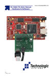
2.5 Board dimensions
Figure 1 below shows dimensions of SBC9302 board and of various connectors on the board.
© SPJETPL All Rights Reserved. (www.spjsystems.com)
Page 5 of 36
SBC9302 User's Manual
Figure 1
© SPJETPL All Rights Reserved. (www.spjsystems.com)
Page 6 of 36
SBC9302 User's Manual
3 SBC9302 Development Setup:
Although stand-alone (no OS) applications can be run on SBC9302, it is primarily intended to run Linux based
applications. The SBC9302 ships with Linux pre-installed. As described in the “specifications” section above, the
board has many interfaces – including RS232 and Ethernet. During development, these 2 interfaces are very
useful.
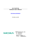
Figure 2 depicts typical setup required for developing Linux based or stand-alone applications for SBC9302.
SBC9302 Typical Development Setup
[Optional] Color or
monochrome LCD
panel
[Optional] LCD panel
interface board
[Optional] PC/104
modules
PC/104 bus
SBC9302
Desktop or
Laptop
computer
with Linux
UART1
GPIO
USB1
Serial cable.
COM1
UART0 (RS232)
USB2
Ethernet
Ethernet
LAN cables
[Optional] LAN Hub
or Switch
LAN cable
LAN / Internet access.
Figure 2
Items marked in Yellow are mandatory:
• SBC9302 deliverables include the serial cable. It also includes 1 Amp. power supply, suitable for
SBC9302 board alone.
• Computer with Linux shall be arranged by user.
Items marked in Lavender are optional:
• If the computer does not need connection to LAN, then Hub/Switch may not be used. Instead, LAN cable
maybe connected directly between Computer and SBC9302. Either straight or crossed cable maybe
used, because the Ethernet physical layer on SBC9302 is capable of swapping Rx and Tx if necessary.
© SPJETPL All Rights Reserved. (www.spjsystems.com)
Page 7 of 36
SBC9302 User's Manual
•
PC/104 compatible modules are optional and maybe connected only if the applications requires them.
E.g. some Industrial control applications may connect PC/104 compatible I/O module. CAUTION:
Connecting PC/104 modules may require more current than what the standard power supply can provide.
We recommend using 3 Amp. power supply (to be purchased separately).
• LCD panel interface board and LCD are also optional and maybe connected only if the applications
requires them. CAUTION: Connecting LCD panel interface board and LCD may require more current than
what the standard power supply can provide. We recommend using 3 Amp. power supply (to be
purchased separately).
Other optional items not shown in Figure2:
• Various types of USB peripherals maybe optionally connected to USB1 and USB2 interfaces of
SBC9302. Examples are USB keyboard, USB mouse, digital camera, webcam, pen-drive,
printer…CAUTION: Some USB peripherals consume large amount of power and hence the standard
power supply may not be enough in such situations. We recommend using 3 Amp. power supply (to be
purchased separately).
• GPIO pins can be used to connect to various peripherals. Please check voltage levels and current drive
capabilities in the EP9302 documentation.
• Other features of EP9302 – such as ADC, SPI interface and so on – are accessible to users through the 2
GPIO connectors. Suitable external devices maybe connected here.
It is possible to program the board through serial port or through Ethernet LAN, with the help of setup as shown
above. Required software tools are either provided in the CD or are open source, so you may download from the
Internet. Thus, no additional tool (apart from above setup) is needed for programming the board.
4 SBC9302 boot options and boot process:
The SBC9302 board has EP9302 processor. It provides various boot options, but only 2 are relevant for SBC9302
users. Hence, only those options are discussed here. Note that, this is a simplified description of boot process.
For more detail description, you may refer to EP9302 documentation.
4.1 Serial boot mode:
In this mode, the EP9302 boots from it’s internal boot ROM – it is pre-programmed when the EP9302 chip ships.
There is a special program inside this boot ROM. Assuming that UART1 is connected to a computer, it attempts
to communicate with it. If successful, the computer downloads a program (binary file); the EP9302 programs it
into the on-board (parallel) flash. This boot mode is used to program the boot-loader or any other stand-alone
application into the SBC9302 board. However, when SBC9302 board ships, a boot loader program is already
programmed into the board; so most users may never need to use this boot option.
4.2 Parallel boot mode:
In this mode, the EP9302 boots from parallel flash. Thus the boot-loader (already programmed into the flash) will
be executed when board is turned ON in this mode.
Selection between serial boot mode and parallel boot mode is done by using a jumper. Refer to the section on
jumper settings for mode details.
4.3 Boot process:
Normally the SBC9302 should be powered ON in parallel boot mode. Only then Linux can boot up. Hence, it is
assumed that board is powered ON in parallel boot mode, unless specified otherwise. The boot process follows
number of steps, as described below:
1. The processor runs boot loader program (redboot) from flash.
2. It uses UART1 for user interface. Thus messages output by redboot can be seen on computer – if it is
connected to UART1 with serial cable and if appropriate terminal program is running on it. Examples of
terminal program are Hyperterminal (on Windows) and minicom (on Linux). COM port setting should be
57600 baud, 8 bits per character, 1 stop bit, no parity.
3. The redboot program can branch to one of the two possibilities – boot Linux or goto redboot command
line mode. Default action is to boot Linux, but user can press Ctrl.C to goto redboot command line mode.
This is useful for downloading new Linux images into flash (described later).
4. By default, redboot will load pre-programmed Linux images (zImage and ramgisk.gz) from flash to RAM
and then run it.
© SPJETPL All Rights Reserved. (www.spjsystems.com)
Page 8 of 36
SBC9302 User's Manual
5. The zImage is self extracting compressed image, so it will uncompress itself and then Linux starts
running.
6. ramdisk.gz is compressed image of root file system. It is is also uncompressed into RAM and then root
filesystem is mounted.
7. Linux uses UART1 as a TTY device. So messages output by Linux and shell prompt can be seen on
computer – if it is connected to UART1 with serial cable and if appropriate terminal program is running on
it. COM port setting should be 57600 baud, 8 bits per character, 1 stop bit, no parity.
When you see shell prompt in the terminal window, it means Linux is up and running. Now you can type standard
Linux commands (like ls, pwd and so on) or type name of an application and press Enter to run that command or
application. Note that supplied default configuration is such that the root user is automatically logged in when
Linux is up.
© SPJETPL All Rights Reserved. (www.spjsystems.com)
Page 9 of 36
SBC9302 User's Manual
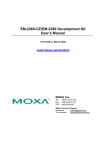
5 Connectors, Jumpers and Switches:
EXT-5V-SEL
JTAG2
Ethernet
SD-CON
USBH-0-1
X2
X1-J1
X1-J2
GP-CON1
GP-CON2
BOOT[0]
WPN
USBD
+5V-SEL
S2
S1
J1
Figure 3
CFGU1-3
CFGU1-2 CFGU1-1
RX2+
RX1+
CFGU2-3 CFGU2-2 CFGU2-1
TX2+
TX1-
RX2-
RX1-
TX2-
TX1+
UART2
UART1
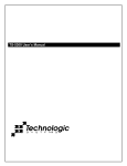
Figure 4
© SPJETPL All Rights Reserved. (www.spjsystems.com)
Page 10 of 36
SBC9302 User's Manual
Locations and names of various connectors and jumpers are shown in Figure 3 and Figure 4.
Note: The processor EP9302 has 2 on-chip UARTs. EP9302 documentation refers to these as UART0 and
UART1. Both these UARTs are made available to user through 2 separate DB9 connectors – named as UART1
and UART2 respectively. In other words:
• EP9302 UART0 is available on connector UART1.
• EP9302 UART1 is available on connector UART2.
Henceforth in this document, the word “UART1” refers to UART1 connector (i.e. EP9302 UART0) and the word
“UART2” refers to UART2 connector (i.e. EP9302 UART1).
5.1 Jumper description:
Viewpoint Reference: Look at the SBC9302 board from front side. The 2 UART connectors should be near the
lower edge. PC/104 connector should be near the left edge.
Conventions used:
• 2 pin jumpers: These can be shorted or open. These 2 conditions are noted as Short or Open,
respectively.
• 3 pin jumpers: 3 conditions are possible in this case: middle and upper pin shorted, middle and lower pin
shorted, or open (no pins shorted). These 3 conditions are noted as Up, Down or Open, respectively.
“Don’t care” condition of a jumper is noted as X.
The jumper setting is clearly described in the table. Row marked with asterisk (*) indicates factory setting.
CAUTION: Only the jumpers described below maybe changed by users, that too within the restrictions as
mentioned below. Changing setting of any other jumper (which is not described below) may cause permanent
damage to the board.
Locations of various jumpers are shown in Figure 3 and Figure 4.
BOOT[0]
This jumper is used to select between serial boot mode and parallel boot mode.
BOOT[0]
Selected boot mode
Open
Serial boot mode
* Short
Parallel boot mode
+5V-SEL and EXT-5V-SEL
These 2 are separate jumpers, but only one maybe shorted at any time, hence described together. With these
jumpers, one of the 2 power sources can be selected: through power jack J1 or through power connector X2.
+5V-SEL
EXT-5V-SEL
Selected power source
Open
Power jack J1
* Short
Open
Short
Power connector X2
CAUTION: Shorting both the above jumpers simultaneously can cause permanent damage to the board and/or to
the power supply. Please short only one of the above 2 jumpers at any time.
WPN
This jumper can be used for flash “write-protection”.
WPN
Flash
Open
Not write protected
*
Short
Write protected
© SPJETPL All Rights Reserved. (www.spjsystems.com)
Page 11 of 36
SBC9302 User's Manual
CFGU1-3, CFGU1-2, CFGU1-1, RX1+, TX1+, TX1-, RX1These are 7 different jumpers, but should be operated together to select one of the 3 possibilities for operation of
UART1:
CFGU1- CFGU1- CFGU1- RX1+ TX1+ TX1- RX1- Selected UART1 operation
3
2
1
Short
Open
Open Up
Up
Up
UART1 works as (3 wire) RS232; RxD, TxD,
* Open
GND signals available on connector
UART1.
Short
Open
Open
Short Down Down Down UART1 works as RS422; Tx+, Tx-, Rx+, Rxsignals available on connector UART1.
Open
Open
Short
Open Open Open Open UART1 works as TTL (3.3V level); RxD,
TxD, GND signals available on connector
GP-CON2.
CAUTION: Any other combination of the above jumpers is invalid and may cause permanent damage to the
board.
CFGU2-3, CFGU2-2, CFGU2-1, RX2+, TX2+, TX2-, RX2These are 7 different jumpers, but should be operated together to select one of the 3 possibilities for operation of
UART2:
CFGU2- CFGU2- CFGU2- RX2+ TX2+ TX2- RX2- Selected UART2 operation
3
2
1
Short
Open
Open Up
Up
Up
UART2 works as (3 wire) RS232; RxD, TxD,
* Open
GND signals available on connector
UART2.
Short
Open
Open
Short Down Down Down UART2 works as RS422; Tx+, Tx-, Rx+, Rxsignals available on connector UART2.
Open
Open
Short
Open Open Open Open UART2 works as TTL (3.3V level); RxD,
TxD, GND signals available on connector
GP-CON2.
CAUTION: Any other combination of the above jumpers is invalid and may cause permanent damage to the
board.
CAUTION: For SBC9302 board versions earlier than V2.0, an errata related to UART1 and UART2 mode applies.
If the revision number printed on the PCB is less than “SBC9302 V2.0”, then please refer to the document
SBC9302_Errata1.
5.2 Connector description:
Locations of various connectors are shown in Figure 3 and Figure 4.
J1
This is power socket. The supplied power supply (in India only) has power jack compatible with this socket. It
provides 7.5VDC (maximum 1 Amp.) to the board. Other necessary voltages are generated on-board. If higher
current is required, then power must be supplied through connector X2 and also jumper setting must be changed
accordingly.
X2
This is a 5 pin relimate connector – alternative to standard power socket (J1). This should be used if more than 1
Amp. current is required (due to PC/104 add-on modules and/or external USB peripherals etc.)
Pin #
Signal
1
GND
2
-5V (not used on-board, but routed to PC/104 connector)
3
-12V (not used on-board, but routed to PC/104 connector)
4
+12V (not used on-board, but routed to PC/104 connector)
5
+5V
© SPJETPL All Rights Reserved. (www.spjsystems.com)
Page 12 of 36
SBC9302 User's Manual
UART1
This connector brings out pins of UART1. Basically both the UARTs have 3 possibilities: RS232 or RS422 or TTL
(3.3V level). One of these 3 options is selected through jumpers. Depending on the selected option, the signals
available on this connector may vary.
When UART1 is configured as RS232.
Pin #
Signal
2
Tx of UART1
3
Rx of UART1
5
GND
1,4,6,7,8,9 No connection.
When UART1 is configured as RS422.
Pin #
Signal
2
Tx- of UART1
3
Rx- of UART1
4
Rx+ of UART1
5
Tx+ of UART1
1,6,7,8,9
No connection.
Note: If ((UART1 is not configured as RS422) and (UART1 is not configured as RS232)), then all pins of
connector UART1 have no connection. In this case, UART1 signals (at 3.3V level) are available on GP-CON2.
UART2
This connector brings out pins of UART2. Basically both the UARTs have 3 possibilities: RS232 or RS422 or TTL
(3.3V level). One of these 3 options is selected through jumpers. Depending on the selected option, the signals
available on this connector may vary.
When UART2 is configured as RS232.
Pin #
Signal
2
Tx of UART2
3
Rx of UART2
5
GND
1,4,6,7,8,9 No connection.
When UART2 is configured as RS422.
Pin #
Signal
2
Tx- of UART2
3
Rx- of UART2
4
Rx+ of UART2
5
Tx+ of UART2
1,6,7,8,9
No connection.
Note: If ((UART2 is not configured as RS422) and (UART2 is not configured as RS232)), then all pins of
connector UART2 have no connection. In this case, UART2 signals (at 3.3V level) are available on GP-CON2.
© SPJETPL All Rights Reserved. (www.spjsystems.com)
Page 13 of 36
SBC9302 User's Manual
JTAG2
This connector brings out JTAG pins of the EP9302 processor. This is a standard 20 pin JTAG connector. Any
third party JTAG based Emulator – which supports standard 20 pin JTAG connector – can be connected here.
The pin description is as below:
Pin #
Signal
1
Vdd (3.3V)
2
Vdd (3.3V)
3
nTRST
4
GND
5
TDI
6
GND
7
TMS
8
GND
9
TCK
10
GND
11
No connection.
12
GND
13
TDO
14
GND
15
nRST
16
GND
17
No connection.
18
GND
19
No connection.
20
GND
© SPJETPL All Rights Reserved. (www.spjsystems.com)
Page 14 of 36
SBC9302 User's Manual
X1-J1 and X1-J2 (PC/104)
These 2 connectors make up the PC/104 interface. Some of the standard PC/104 signals may not be available or
may have somewhat modified meaning, as described below. The pin numbers of these connectors are as shown
in Figure 5 (top view)
A1
D0
B1
C0
Connector
X1-J2
D19
Connector
X1-J1
C19
A32
B32
Figure 5
© SPJETPL All Rights Reserved. (www.spjsystems.com)
Page 15 of 36
SBC9302 User's Manual
X1-J1
Pin #
A1
A2-A9
A10
A11
A12-A31
A32
B1
B2
B3
B4
B5
B6
B7
B8
B9
B10
B11
B12
B13
B14
B15
B16
B17
B18
B19
B20
B21-B22
B23-B25
B26
B27
Standard PC/104 Signal name
IOCHCHK
SD7-SD0
IOCHRDY
AEN
SA19-SA0
0V
0V
RESETDRV
+5 V
IRQ9
-5 V
DRQ2
-12 V
ENDXFR
+12 V
KEY
SMEMW#
SMEMR#
IOW#
IOR#
DACK3
DRQ3
DACK1
DRQ1
REFRESH
SYSCLK
IRQ7-IRQ6
IRQ5-IRQ3
DACK2
TC
B28
BALE
B29
B30
B31-B32
+5 V
OSC
0V
Signal, as available on SBC9302
No connection
DT7-DT0 of EP9302 (3.3 V level, 5V tolerant)
WAITN pin of EP9302 (3.3 V level, 5V tolerant)
Always low
AD19-AD0 of EP9302 (3.3 V level)
GND
GND
RST (goes high during CPU reset)
+5 V
No connection
-5 V or no connection*
No connection
-12 V or no connection*
No connection
+12 V or no connection*
No connection
Always high
Always high
$
WRN of EP9302 (3.3 V level)
$
RDN or EP9302 (3.3 V level)
No connection
No connection
No connection
No connection
No connection
14.7456 MHz clock (3.3 V level)
No connection
INT[2]-INT[0] pins of EP9302 (3.3 V level, NOT 5V tolerant)
No connection
EGPIO12 (i.e. DEOT1) of EP9302 (3.3 V level, NOT 5V
tolerant)
Low when address is in the range 0x1000_0000 to
0x1FFF_FFFF; high otherwise.
+5 V
No connection
GND
© SPJETPL All Rights Reserved. (www.spjsystems.com)
Page 16 of 36
SBC9302 User's Manual
X1-J2
Pin #
C0
C1
C2-C8
C9
C10
C11-C18
C19
D0
D1
D2
D3-D6
D7
D8
D9
D10
D11
D12
D13
D14
D15
D16
D17
D18-D19
Standard PC/104 Signal name
0V
SBHE#
LA23-LA17
MEMR#
MEMW#
SD8-SD15
Key
0V
MEMCS16#
IOCS16#
IRQ10-IRQ12, IRQ15
IRQ14
DACK0
DRQ0
DACK5
DRQ5
DACK6
DRQ6
DACK7
DRQ7
+5 V
MASTER
0V
Signal, as available on SBC9302
GND
Always high
AD23-AD17 of EP9302 (3.3 V level)
Always high
Always high
DT8-DT15 of EP9302 (3.3 V level, 5V tolerant)
GND
GND
Should not be used.
Should not be used.
No connection
No connection
No connection
No connection
No connection
No connection
No connection
No connection
No connection
No connection
+5 V
No connection
GND
* These pins are merely shorted with corresponding pins of connector X2. Thus, if these voltages are applied to
the SBC9302 through connector X2, then and only then will these voltages be available on connector X1-J1.
$ These signals are generated by on-board CPLD. If address is in the range 0x1000_0000 to 0x1FFF_FFFF, then
the WRN or RDN signals of EP9302 are passed onto X1-J1 connector; otherwise pins B13 and B14 of X1-J1
remain high, regardless of the status of WRN and RDN pins of EP9302.
Note: Signals highlighted in light-green color are generated by on-board CPLD and are outputs of SBC9302. The
meaning of these signals can be changed on request for high volume customers.
CAUTION: Many signals on X1-J1 and X1-J2 connectors are marked as NOT 5V tolerant. These are inputs to
the SBC9302 board. Users must take care that voltage on these pins shall never exceed 3.3V, as it may cause
permanent damage to the board.
Ethernet
This is standard RJ45 connector. It provides Ethernet interface. Standard LAN cable with RJ45 jack can be
connected here. The on-board Ethernet physical layer can automatically swap Tx and Rx lines. As a result, either
straight or crossed LAN cable can be used.
SD-CON (SD-Card)
SD-Card can be inserted into this connector. It has standard SD-Card connector pin-out. This connector is on the
bottom side of SBC9302 board.
© SPJETPL All Rights Reserved. (www.spjsystems.com)
Page 17 of 36
SBC9302 User's Manual
USBH-0-1 (2 USB Host Interfaces)
This is a “double-decker” connector – i.e. 2 USB host interface connectors put together. Standard USB
peripherals – like pen-drive, digital camera, webcam etc. – can be connected to either of these 2 USB host
interfaces. Both these are standard USB type A connectors.
USBD (USB Device Interface)
This is a standard USB type B connector. It provides USB device interface. This can be connected to USB port of
a computer, through standard USB cable.
GP-CON1
This connector brings out some of the GPIO pins and some other miscellaneous signals.
Pin #
Signal
Pin #
1
EGPIO15
2
EGPIO0
3
EGPIO14
4
EGPIO1
5
EGPIO13
6
EGPIO2
7
EGPIO12
8
EGPIO3
9
FGPIO3
10
EGPIO4
11
FGPIO2
12
EGPIO5
13
FGPIO1
14
EGPIO6
15
HGPIO2
16
EGPIO7
17
HGPIO3
18
EGPIO8
19
HGPIO4
20
EGPIO9
21
HGPIO5
22
EGPIO10
23
ADC0
24
EGPIO11
25
ADC1
26
ADC4
27
ADC2
28
+5 V
29
ADC3
30
+3.3 V
31
GND
32
GND
GP-CON2
This connector brings out some of the GPIO pins and some other miscellaneous signals.
Pin #
Signal
Pin #
1
GND
2
ASYNC
3
+3.3 V
4
ASDO
5
No connection
6
SCLK1
7
No connection
8
SFRM1
9
No connection
10
SSPRX1
11
DTRn
12
SSPTX1
13
RTSn
14
INT[3]
15
DSRN
16
INT[1]
17
CGPIO
18
INT[0]
19
ARSTN
20
ABITCLK
21
ASDI
22
CTSN
23
RxD of UART1 (TTL, 3.3V level)
24
TxD of UART1 (TTL, 3.3V level)
25
RxD of UART2 (TTL, 3.3V level)
26
TxD of UART2 (TTL, 3.3V level)
27
EECLK
28
+3.3 V
29
EEDAT
30
+5 V
31
GND
32
GND
CAUTION: All signals on GP-CON1 and GP-CON2 connectors are directly pins of EP9302 processor and these
are NOT 5V tolerant. Users must take care that voltage on these pins shall never exceed 3.3V, as it may cause
permanent damage to the board.
© SPJETPL All Rights Reserved. (www.spjsystems.com)
Page 18 of 36
SBC9302 User's Manual
5.3 Switches description:
S1
This is a push-button for “user reset”. Pressing this switch momentarily will apply a reset pulse to the RSTOn pin
of EP9302. It resets the entire processor, except certain system variables such as RTC, SDRAM refresh
control/global configuration, and the Syscon registers. If PLLs are enabled, user reset does NOT disable or reset
the PLLs. They retain their frequency settings.
S2
This is a push-button for “power-on reset”. Pressing this switch momentarily will apply a reset pulse to the PRSTn
pin of EP9302. It resets the entire processor, without any exceptions.
We recommend using the S2 switch for resetting the SBC9302 board.
6 GPIO: Usage and Availability
On the EP9302 processor, there are total 37 GPIO pins. However, some of these pins may have alternate
functions assigned by the EP9302 processor. Further, some other pins are used on the SBC9302 board. Some
other pins are available to user as GPIO pins. The table below lists such information related to these GPIO pins:
Please note that some GPIO pins maybe brought out on GPCON1 or GPCON2 connectors, yet those may not be
available to user or maybe conditionally available. Please take care not to connect any external signal to such
pins.
6.1 GPIO Table:
CGPIO0
EGPIO15
EGPIO14
EGPIO13
EGPIO12
EGPIO11
EGPIO10
EGPIO9
EGPIO8
EGPIO7
EGPIO6
EGPIO5
EGPIO4
I/O
capability
Ip/Op/OD
Ip/Op/OD
Ip/Op/OD
Ip/Op/OD
Ip/Op/OD
Ip/Op/OD
Ip/Op/OD
Ip/Op/OD
Ip/Op/OD
Ip/Op/OD
Ip/Op/OD
Ip/Op/OD
Ip/Op/OD
Ip/Op/OD
Ip/Op/OD
Ip/Op/OD
Ip/Op/OD
Interrupt
capability
No
No
No
No
No
Yes
Yes
Yes
Yes
Yes
Yes
Yes
Yes
Yes
Yes
Yes
Yes
Available
on
connector?
No
No
GPCON2
GPCON2
GPCON2
GPCON1
GPCON1
GPCON1
GPCON1
GPCON1
GPCON1
GPCON1
GPCON1
GPCON1
GPCON1
GPCON1
GPCON1
EGPIO3
EGPIO2
EGPIO1
EGPIO0
FGPIO3
FGPIO2
FGPIO1
Ip/Op/OD
Ip/Op/OD
Ip/Op/OD
Ip/Op/OD
Ip/Op/OD
Ip/Op/OD
Ip/Op/OD
Yes
Yes
Yes
Yes
Yes
Yes
Yes
GPCON1
GPCON1
GPCON1
GPCON1
GPCON1
GPCON1
GPCON1
#
1
2
3
4
5
6
7
8
9
10
11
12
13
14
15
16
17
18
19
20
21
22
23
24
Pin
name
PE0
PE1
PG0
PG1
PC0
PB7
PB6
PB5
PB4
PB3
PB2
PB1
PB0
PA7
PA6
PA5
PA4
Another
name
PA3
PA2
PA1
PA0
PF3
PF2
PF1
Connector
Pin #
N.A.
N.A.
27
29
17
1
3
5
7
24
22
20
18
16
14
12
10
© SPJETPL All Rights Reserved. (www.spjsystems.com)
8
6
4
2
9
11
13
Available
for user?
No
No
[Note1]
[Note1]
Yes
Yes
Yes
Yes
Yes
[Note2]
[Note2]
Yes
Yes
Yes
Yes
Yes
Yes
[Note3]
Yes
Yes
Yes
[Note4]
Yes
Yes
Functionality
in SBC9302
Boot LED
Boot LED
SCL for RTC
SDA for RTC
None.
None.
None.
None.
None.
USB device
USB device
None.
None.
None.
None.
None.
None.
[optional]
RS485
direction
control
None.
None.
None.
SD-Card
None.
None.
Page 19 of 36
SBC9302 User's Manual
25
26
27
28
29
30
31
32
33
34
35
36
37
PH2
PH3
PH4
PH5
MDIO
CTSn
DSRn /
DCDn
RTSn
DTRn
ARSTn
INT3
INT1
INT0
HGPIO2
HGPIO3
HGPIO4
HGPIO5
Ip/Op/OD
Ip/Op/OD
Ip/Op/OD
Ip/Op/OD
Ip/Op/OD
Input
No
No
No
No
No
No
GPCON1
GPCON1
GPCON1
GPCON1
No
GPCON2
Input
Output
Output
Output
Input
Input
Input
No
No
No
No
Yes
Yes
Yes
GPCON2
GPCON2
GPCON2
GPCON2
GPCON2
GPCON2
GPCON2
15
17
19
21
22
Yes
Yes
Yes
Yes
No
Yes
None.
None.
None.
None.
Ethernet PHY
None.
15
13
11
19
14
16
18
Yes
Yes
Yes
Yes
No
[Note5]
[Note2]
None.
None.
None.
None.
Ethernet PHY
PC104
USB device
N.A.
Note1: This pin is used for RTC interface. This can be used as GPIO if RTC is not soldered on the board.
Note2: This pin is used for USB device interface. This can be used if components related to "USB device
interface" are not soldered on the board.
Note3: By default, this can be used as GPIO. But optionally, it can be used as "direction control" pin for RS485
interface. This is possible if a 0 Ohm resistor is soldered on the board.
Note4: This pin is used for SD-Card interface. This can be used if components related to "SD-Card interface" are
not soldered on the board.
Note5: This pin is used for PC/104 interface. This can be used if components related to "PC/104 interface" are
not soldered on the board.
Note6: Some GPIO pins have input and output capability (direction selectable by software), some others have
only input capability, and some others have only output capability. Pins are highlighted in different colors to
distinguish such capabilities.
CAUTION: Soldering or de-soldering any part on / from the board will make warranty void. However, OE
customers may request quotations for customized version of SBC9302 board. Some features on this board can
be removed (in order to reduce power consumption and price). These features are:
• RTC with battery backup (by default, this feature is included).
• USB device interface (by default, this feature is included).
• RS485 direction control (by default, this feature is not included).
• SD-Card interface (by default, this feature is included).
• PC/104 interface (by default, this feature is included).
Note that Minimum Order Quantities (MOQ) apply for such customized version of board.
Please do not solder or de-solder any component on the board, because that will make the warranty void.
6.2 SBC9302Test board:
This is a small “test board” designed to connect to SBC9302 board through GPCON1 and GPCON2 connectors.
• It has 27 LEDs that can indicate the status of corresponding I/O pin (LED glowing means pin is defined as
output and is LOW; LED off means either pin is defined as input or is HIGH).
• It has 3 jumpers connected to DTRn, RTSn and INT[1] pins. These are “input only” pins. On this test
board, these pins are also pulled up. Thus if shorting link is placed on a jumper, the corresponding input
pin will receive LOW level; otherwise it will receive HIGH level.
• It has 5 potentiometers. Two ends of potentiometers are connected to 3.3V and GND. The middle
(variable) end is connected to analog inputs ADC0 through ADC4. User may turn these potentiometers to
vary the analog voltage at the ADC inputs, in the range 0 to 3.3V.
Thus, the SBC9302Test board comes very handy while experimenting with the SBC9302 board.
© SPJETPL All Rights Reserved. (www.spjsystems.com)
Page 20 of 36
SBC9302 User's Manual
7 PC/104 Addressing:
7.1 What is PC/104 bus:
PC/104 bus is basically designed for boards with x86 architecture CPU. The x86 architecture supports separate
memory space and I/O space. The PC/104 bus has signals for both – memory space and I/O space. Signals for
I/O space are:
• 16 bit address
• 8 or 16 bit data
• IOWN (active low Write strobe)
• IORN (active low Read strobe)
• Some other control signals
Signals for memory space are:
• 24 bit address
• 8 or 16 bit data
• MEMWN (active low Write strobe)
• MEMRN (active low Read strobe)
• Some other control signals
Common address and data lines are used for memory space and I/O space; but some control signals are different
– notably the read and write strobes for memory space and I/O space are different.
7.2 How is PC/104 bus implemented on SBC9302:
The processor on this board is EP9302 – an ARM9 processor. Unlike x86 architecture, it has a single 32 bit
address space. There is no such thing as “I/O”. It means that if you want to connect external peripherals to this
processor, those have to be “memory mapped”. Thus this processor can not (by itself) support PC/104 bus, due
to it’s architectural difference as compared to x86.
However, we have attempted to support PC/104 bus as closely as possible, so that even third-party PC/104
modules can be connected to SBC9302. The SBC9302 board has a separate CPLD to generate some PC/104
control signals – which the processor does not generate by itself.
Please refer to PC/104 connector description: it marks such signals (that are generated by CPLD) with a different
color. It is possible to change the functionality of such signals by changing the CPLD program. We can make such
changes for OEM customers.
7.3 Address range:
The PC/104 control signals (notably IOWN, IORN, MEMWN, MEMRN) are activated only when the EP9302
processor accesses a certain address range. In fact, it is 0x1000_0000 to 0x10FF_FFFF. This is further divided,
as described in the table below: (memory and I/O spaces are marked with different colors).
#
1
2
3
4
5
6
7
Description
PC/104 address range for SBC9302: i.e. PC/104 control
signals can be active, only when address is in this range.
PC/104 memory space for SBC9302: i.e. MEMWN and
MEMRN signals can be active only when address is in this
range.
PC/104 I/O space for SBC9302: i.e. IOWN and IORN signals
can be active only when address is in this range.
Address range reserved for “SLPIB” (LCD panel interface
board - an SPJ product).
Reserved address space (must not be used for any PC/104
module)
Address range (within memory space) available for other
PC/104 modules.
Address range (within I/O space) available for other PC/104
modules.
© SPJETPL All Rights Reserved. (www.spjsystems.com)
Start address
0x1000_0000
End address
0x10FF_FFFF
Size
16 MB
0x1000_0000
0x107F_FFFF
8 MB
0x1080_0000
0x10FF_FFFF
8 MB
0x1000_0000
0x1007_FFFF
512 KB
0x1008_0000
0x100F_FFFF
512 KB
0x1010_0000
0x107F_FFFF
7 MB
0x1080_0000
0x10FF_FFFF
8 MB
*
Page 21 of 36
*
SBC9302 User's Manual
* The actually usable I/O space is not 8 MB though, due to the fact that: PC/104 I/O space uses only 16 bit
addresses. Thus total I/O space is by definition limited to 64KB only. This 64KB is mapped to the 8MB region
0x1080_0000 to 0x10FF_FFFF on the SBC9302. Further, most PC/104 modules that use I/O space often use
only addresses within 0x0300 to 0x03FF (i.e. for the SBC9302, it will be 0x10mn_0300 to 0x10mn_03FF; where
m is any hexadecimal digit in the range 8 through F and n is any hexadecimal digit in the range 0 through F).
Thus actually used I/O space maybe even less.
7.4 Address selection for SPJ manufactured PC/104 modules:
LCD panel interface board:
SLPIB is an LCD panel interface board, fully compatible with SBC9302. It does not offer “address selection”.
Instead, it uses a fixed address range of 0x1000_0000 to 0x1007_FFFF.
Other:
Other PC/104 modules manufactured by SPJ also use only memory space. These boards usually provide 3
switches or jumpers for selecting one of the 7 possible address ranges. Though 3 jumpers can make 8
combinations, one is forbidden – because it is partly used by SLPIB and partly reserved for future use. This
“forbidden” combination is marked in red below.
Start address
End address
Remark
Jumper
Jumper
Jumper
corresponding corresponding corresponding
to A20
to A21
to A22
ON
ON
ON
0x1000_0000 0x100F_FFFF Partly used by SLPIB, partly
reserved for future use.
ON
ON
OFF
0x1010_0000 0x101F_FFFF 1 MB available space.
ON
OFF
ON
0x1020_0000 0x102F_FFFF 1 MB available space.
ON
OFF
OFF
0x1030_0000 0x103F_FFFF 1 MB available space.
OFF
ON
ON
0x1040_0000 0x104F_FFFF 1 MB available space.
OFF
ON
OFF
0x1050_0000 0x105F_FFFF 1 MB available space.
OFF
OFF
ON
0x1060_0000 0x106F_FFFF 1 MB available space.
OFF
OFF
OFF
0x1070_0000 0x107F_FFFF 1 MB available space.
8 Development Tools:
Most of the tools required for developing applications for SBC9302 are supplied in the accompanying CD.
However, these tools are not SPJ products. These are open source tools and can be downloaded from Internet.
Important tools required are:
1. gcc compiler: This is native compiler – i.e. runs on Linux computer and generates executables for Linux
computer. This is generally part of the Linux installation on the computer.
2. arm-elf-gcc: This is cross compiler – i.e. runs in Linux computer and generates executables for standalone ARM targets. This is is useful for generating executable file of boot-loader. Boot-loader is a standalone application, since it starts before Linux. This can be downloaded from Internet. This is also included
on the accompanying CD.
3. arm-linux-gcc: This is cross compiler – i.e. runs in Linux computer and generates executables for ARM
Linux targets. This is useful for generating Linux applications to run on SBC9302 board. This can be
downloaded from Internet. This is also included on the accompanying CD.
4. make: This is Linux standard make utility, useful for building complex projects. This is generally part of the
Linux installation on the computer.
5. minicom: This is a serial terminal utility – similar to Hyperterminal of Windows. This can be part of Linux
OS installed on the computer. If not, this can be installed later – from the Linux installation CD/DVD.
Alternatively, this can be also downloaded from internet.
6. tftp: Stands for Trivial File Transfer Protocol – it is a useful tool for transferring files over Ethernet LAN.
This can be also part of Linux OS installed on the computer. If not, this can be installed later – from the
Linux installation CD/DVD. Alternatively, this can be also downloaded from internet.
© SPJETPL All Rights Reserved. (www.spjsystems.com)
Page 22 of 36
SBC9302 User's Manual
7. Many useful makefiles, configuration files and some shell scripts can be also considered part of the
development tool. Many of these are supplied in the accompanying CD.
9 Preparing computer:
As described earlier, Linux computer is necessary. It is assumed that Linux OS is already installed on the user’s
computer. Several different Linux distributions are available. We have used computer with Mandriva Linux (spring
2007) installed in it. However, procedure described here should work well on other Linux distributions also –
possibly with minor differences. Following steps maybe followed to make this computer ready for developing
applications to run on SBC9302.
1. Login into Linux with your normal username (say user1).
2. Insert the accompanying CD into CD-ROM drive.
3. A new window may pop-up with contents of CD in it.
4. Open a root shell (Konsole) i.e. login as root.
5. The inserted CD will be generally automatically mounted in a folder /media/cdrom or some such. Goto
that folder using cd command (e.g. cd /media/cdrom).
6. Type sh install.sh on command line and press Enter. The CD contains a shell script file – install.sh –
the same will be executed now.
7. The script will ask for username. Enter your username. Then the script will automatically copy workspace
into the home folder of this user. Suppose your username is “user1”, then the workspace will be created
in the folder /home/user1/sbc9302.
8. The script execution may go on for a few minutes (depends on your computer speed) as it copies several
files from CD to your computer. Finally, it displays the message “Installation finished”.
9. Now path to gcc compiles must be set. To do so, open the file /home/user1/.bash_profile. Locate PATH
variable in it and change it to
PATH=$PATH:$HOME/bin:/usr/local/arm/3.2.1-elf/bin:/usr/local/arm/4.1.1-920t/bin
10. Now you may close the root shell, log-off and login again with your normal username (say user1).
11. You may verify correct installation of all 3 versions of gcc. To do so, you may open a shell and:
a. Type “gcc” and press Enter. You should see the message “gcc: no input files”. This indicates that
gcc compiler could be run, but since no input filename was specified, it did not perform any
action.
b. Similarly, type “arm-elf-gcc” and press Enter. You should see the message “gcc: no input files”.
c. Similarly, type “arm-linux-gcc” and press Enter. You should see the message “gcc: no input files”.
If any one of the above 3 compilers do not work as expected, then it means that workspace may not be
correctly installed. You may repeat the process more carefully.
With the above steps, the workspace is installed and the computer is ready for developing applications to run on
SBC9302. Here it is assumed that tftp and minicom are properly installed already.
10 Develop an application, download it into SBC9302 and run it:
Although there are many ways to do this, the simplest way is described here.
1. Development setup as shown in Figure2 should be prepared.
2. The workspace installed in /home/user1/sbc9302 folder contains several sample applications. The
simplest and fastest way of creating your own applications is to modify an existing sample application.
These sample applications exist in folders named spj_appl1, spj_appl2 etc. under
/home/user1/sbc9302/packages folder.
3. You may modify the main.c file in one such sample application folder. Note that by doing so, you are
destroying the original sample application supplied by us. However, you can always install the original
sample application again from the accompanying CD, as described in previous section.
4. When you are through with modifications in main.c, you may save it. Then select all object files in this
folder – all files with extension .o – and delete those. Similarly, an (ARM) executable file also exists in this
folder – it has the same name as the folder – i.e. spj_appl1 or spj_appl2 etc. Delete this executable file
also.
5. Then start the shell window. Goto the folder /home/user1/sbc9302. Type “make” and press Enter. Your
application will be built along with other necessary files and new Linux images will be created in the folder
/home/user1/sbc9302/images/9302.
6. You will have to manually copy the images files (ramdisk.gz and zImage) into the TFTP root folder. E.g. if
TFTP root folder is /home/user1/tftpboot, then copy these 2 files into that folder.
© SPJETPL All Rights Reserved. (www.spjsystems.com)
Page 23 of 36
SBC9302 User's Manual
7. In the shell window, you may now start minicom. Use setting 57600,8,N,1.
8. Keep the SBC9302 board in parallel mode (this is the default factory setting). Turn it ON. Within 1-2
seconds, you should see the character ‘+’ in minicom. This is output by the redboot boot-loader program.
9. After a while, you will see more messages from redboot. Finally, it will prompt you to “press Ctrl.C to
abort”. If you do not press any key for a few seconds (typically within 5 seconds), then it will go on to load
Linux. You may press Ctrl.C to abort this, so that redboot command line prompt will be displayed.
10. At this prompt, you can type various redboot commands.
11. With these commands, you can configure IP address of SBC9302, download files from computer,
program those into flash and so on. You may use following commands to program new Linux images into
the board:
a. You may use command “ip_address” to set IP address of SBC9302 and to inform IP address of
host computer to it. Example:
ip_address –l 192.168.1.200 –h 192.168.1.151
What follows “-l” is local IP address, i.e. that of SBC9302. What follows “-h” is host IP address,
i.e. that of the computer. Note that whatever IP address you assign to SBC9302 must be unique
on your LAN.
b. You may use command “load” to transfer an image from computer to the RAM of SBC9302, via
Ethernet LAN. Example:
load –r –v –b 0x800000 ramdisk.gz
This will transfer the file /home/user1/tftpboot/ramdisk.gz from computer to SBC9302 RAM.
c. You may use command “fix create” to burn the image from RAM to flash – so that it will be there
even after power OFF. Example:
fis create –b 0x800000 –l 0x300000 –f 0x60040000 –e 0x800000 –r 0x800000 ramdisk.gz
This will program the image from RAM to flash, with the name “ramdisk.gz”.
d. Similarly, you may use load and fis create commands again to copy zImage into RAM and then
burn it into flash, respectively. Example:
load –r –v –b 0x80000 zImage
fis create –b 0x80000 –l 0x200000 –f 0x60400000 –e 0x80000 –r 0x80000 zImage
These will transfer the file /home/user1/tftpboot/zImage from computer to SBC9302 RAM and
then program it into flash, with the name “zImage”.
e. Thus the 2 new Linux images have been programmed into flash.
12. Now reset the board. As usual, character ‘+’ should appear in minicom window and redboot will start. But
this time, do not press Ctrl.C. After waiting for about 5 seconds, it will start loading Linux images and then
run it.
13. You will see several messages – output by Linux, during booting up – in the minicom window.
14. Finally, following message will appear: “Please press Enter to activate this console.”
15. Press Enter and you will see a command prompt. Now Linux is up and running on SBC9302. Now you
can use general Linux commands by typing it’s name in the minicom window and pressing Enter.
16. The executables of all sample applications are in the /usr/bin folder in SBC9302. These have names such
as spj_appl1, spj_appl2 etc. You may run your application simply by typing it’s name and pressing
Enter. E,g type /usr/bin/spj_appl1 and press Enter. Your application should run.
11 Running SBC9302 (with windows)
•
•
Connect serial cable from uart1 to RS232 port of PC.
Open HyperTerminal with following settings. (Select available COM port you have).
© SPJETPL All Rights Reserved. (www.spjsystems.com)
Page 24 of 36
SBC9302 User's Manual
Click on configure and select COM port properties. Usually COM port numbering starts from COM1,COM2..
(If you are using usb2serial converter, it may use higher COM number. Check Device manager for list of available
COM ports)
Use 576000 baud rate.
© SPJETPL All Rights Reserved. (www.spjsystems.com)
Page 25 of 36
SBC9302 User's Manual
Click OK and click Call from the menu
Now connect the Power adaptor and switch ON the power.
On the terminal window, you will see some messages flashing.
Finally following message will appear.
Please press Enter to activate this console.
Press Enter and you will see a command prompt. Now SBC9302 is ready to work with a serial console. Here you
can use general Linux commands.
BusyBox v1.1.3 (2007.05.14-06:16+0000) Built-in shell (ash)
Enter 'help' for a list of built-in commands.
~ #
Now SBC9302 is running Linux, and what you see on serial console is like a Linux command shell (Of course with
limited features)
Please go to the section “Running Applications” for more details.
© SPJETPL All Rights Reserved. (www.spjsystems.com)
Page 26 of 36
SBC9302 User's Manual
12 Running SBC9302 (with Linux)
•
•
•
To access SBC9302 in Linux, we have to setup minicom on the Linux desktop.
Login as root on command line window, type minicom –s
Select minicom settings by pressing Ctrl-A then Z. Go to Serial Port setup.
•
Select /dev/ttyS0 as serial device. Select lock file location as your home folder to avoid access
restrictions. Baud rate must be 576000 and No flow control.
•
•
•
Now press escape and then save setup as dfl.
Now open command line with your user login(not a root login)
Type minicom it will open minicom window. You can check if the serial port setup is same as we entered
earlier.
© SPJETPL All Rights Reserved. (www.spjsystems.com)
Page 27 of 36
SBC9302 User's Manual
Now exit this setup and switch on the board.
13 More about TFTP and redboot.
(Note: Messages as displayed on serial terminal are formatted in Courier new)
We load total 4 images on sbc9302 depending on the requirements.
1) Redboot - (Loaded from serial port) Do not change redboot , unless you are sure about what you are
doing.
2) zImage – (Loaded from ethernet) Linux Kernel image.
3) Ramdisk.gz – (Loaded from ethernet) Linux root file system.
4) part.jffs2 – (Loaded from ethernet) JFFS2 file system partition.
Usually redboot will be fixed and need not be changed. Part.jffs2 will change only if you need to modify jffs2
partition size. So in practice, you may need to modify on zimage and ramdisk.gz
Linux images can be downloaded from redboot using TFTP protocol.
First , we have to setup TFTP Server.
13.1 TFTP Setup on Linux Machine.
Xinetd, TFTP and TFTP server packages must be installed to run tftp server on linux desktop.
Following instructions are applicable for mandriva Linux and should be similar for other distributions too.
Once xinetd and tftp server are installed, you will see a tftp file in /etc/xinetd.d/tftp path.
Few setting of tftp are done during installation.
Login as root in terminal window and edit this file.
Here, change the path of tftpboot folder as marked in following structure. Here my username is bhal so the
path becomes /home/bhal/tftpboot. Replace it with your username.
service tftp
{
disable
= no
socket_type
= dgram
© SPJETPL All Rights Reserved. (www.spjsystems.com)
Page 28 of 36
SBC9302 User's Manual
protocol
wait
user
server
server_args
per_source
cps
flags
=
=
=
=
=
=
udp
yes
root
/usr/sbin/in.tftpd
-c -s /home/bhal/tftpboot
11
= 100 2
= IPv4
}
Now we need to restart xinetd service to make tftp functional. Reboot Linux desktop and tftp server must be
functional now.
To verify it , refer section Loading Linux Images
13.2 TFTP Setup on winXP Machine
•
•
•
•
Basically we need two tools, hyper terminal and a TFTP server package (supplied in CD).
Instead of hyper terminal, we can use any other terminal supporting serial protocols like tty,ansi.
Install “tftpsetup.exe”
You need to specify a folder to read and write images.
Goto Manage repositories…
Then select a folder to read and write from board.
© SPJETPL All Rights Reserved. (www.spjsystems.com)
Page 29 of 36
SBC9302 User's Manual
Once we setup TFTP folder on windows machine, we can exchange files between windows machine and
SBC9302 board. SBC9302 is a TFTP client and it reads or writes file to TFTP server.
To make TFTP work in SBC9302, we need to setup Ethernet.
13.3 Ethernet Setup in Redboot
Reset the board and press Ctrl-C when prompted to do so.
Executing boot script in 5.000 seconds - enter ^C to abort
It will go to the redboot prompt
RedBoot>
Here we can issue redboot commands.
To view current Ethernet settings in Redboot, type ip_address it will show the default settings.
RedBoot>ip_address
IP: 192.168.1.210/255.255.255.0, Gateway: 192.168.1.10
Default server: 192.168.1.151
It will display current IP address. Here 192.168.1.210 is IP address of SBC9302.
To change IP address and/or TFTP server, issue following command.
RedBoot> ip_address -l 192.168.1.200 -h 192.168.1.151
IP: 192.168.1.200/255.255.255.0, Gateway: 192.168.1.10
Default server: 192.168.1.151
Here 192.168.1.200 is IP address of SBC9302 and 192.168.1.151 is IP address of host machine where you
have configured the TFTP server.
Now we can check ethernet connectivity by pinging the host.
RedBoot> ping -n 5 -h 192.168.1.151
Network PING - from 192.168.1.210 to 192.168.1.151
PING - received 5 of 5 expected
© SPJETPL All Rights Reserved. (www.spjsystems.com)
Page 30 of 36
SBC9302 User's Manual
When it says it has received some packets out of expected., then there is ethernet connectivity between
SBC9302 and TFTP server. Now the setup is ready to download images.
13.4 Default memory partitions
To check existing memory partitions issue following command on redboot prompt
RedBoot> fis list
Name
RedBoot
ramdisk.gz
zImage
jffs2
FIS directory
RedBoot config
FLASH addr
0x60000000
0x60040000
0x60400000
0x60600000
0x607E0000
0x607FF000
Mem addr
0x60000000
0x00800000
0x00080000
0x00800000
0x607E0000
0x607FF000
Length
0x00040000
0x00300000
0x00200000
0x00100000
0x0001F000
0x00001000
Entry point
0x00000000
0x00800000
0x00080000
0x00800000
0x00000000
0x00000000
13.5 Loading Linux Images
To re-load ramdisk.gz and zimage, we need to overwrite them. This is done by first loading the files into RAM
and then writing these images from ram to flash. First load file to RAM
RedBoot> load -r -v -b 0x800000 ramdisk.gz
Using default protocol (TFTP)
|
Raw file loaded 0x00800000-0x00a43ac6, assumed entry at 0x00800000
Now overwrite ramdisk, It will ask for confirmation, since it already exists. Type y and press enter when
asked.
RedBoot> fis create -b 0x800000 -l 0x300000 -f 0x60040000 -e 0x800000 -r 0x80000
0 ramdisk.gz
An image named 'ramdisk.gz' exists - continue (y/n)?y
... Erase from 0x60040000-0x60340000: ........................
... Program from 0x00800000-0x00b00000 at 0x60040000: ........................
... Unlock from 0x607e0000-0x60800000: .
... Erase from 0x607e0000-0x60800000: .
... Program from 0x01fe0000-0x02000000 at 0x607e0000: .
... Lock from 0x607e0000-0x60800000: .
It over writes ramdisk.gz
Now load zImage
RedBoot> load -r -v -b 0x80000 zImage
Using default protocol (TFTP)
/
Raw file loaded 0x00080000-0x00230b1f, assumed entry at 0x00080000
Now overwrite zimage, It will ask for confirmation, since it already exists. Type y and press enter when asked.
RedBoot> fis create -b 0x80000 -l 0x200000 -f 0x60400000 -e 0x80000 -r 0x80000 z
Image
An image named 'zImage' exists - continue (y/n)?y
... Erase from 0x60400000-0x60600000: ................
... Program from 0x00080000-0x00280000 at 0x60400000: ................
... Unlock from 0x607e0000-0x60800000: .
... Erase from 0x607e0000-0x60800000: .
© SPJETPL All Rights Reserved. (www.spjsystems.com)
Page 31 of 36
SBC9302 User's Manual
... Program from 0x01fe0000-0x02000000 at 0x607e0000: .
... Lock from 0x607e0000-0x60800000: .
Here we have completed basic procedure to update the zimage and ramdisk.gz files.
To confirm whether the downloaded software works, we need to reset. Issue reset command.
RedBoot> reset
... Resetting.
The board software will reboot, do not interrupt redboot, let it load the Linux. Wait till you get following
message
Please press Enter to activate this console.
Now press enter. It will display this message. Now, we have running a new Linux software.
BusyBox v1.1.3 (2007.05.14-06:16+0000) Built-in shell (ash)
Enter 'help' for a list of built-in commands.
~ #
14 Installation tips for desktop Linux
•
•
•
•
•
•
•
•
•
Use older machine to install desktop Linux. It is difficult to get all necessary drivers when you install it on
a new machine. Usually, manufacturer does not provide motherboard drivers for Linux. Drivers are
usually inside the kernel. So it is better to use latest Linux distribution, so that we get all necessary
drivers. Supplied Linux distribution was compiled in Apr07. So it is safe to use a PC, which was
purchased before that. (Linux installation is supplied on, as it is basis and we are not supporting the
same, users are free to use any Linux distribution.)
Use Supplied DVD-ROM disk and install Mandriva Linux 2007.1, which includes necessary packages for
development.
Allocate at least 15-20GB free space for installation. Recommended sizes are: 8GB for root partition,
1.5GB for swap and 5-10GB for home partition.
During installation there is an option to copy entire installation media to hard disk. Choose this option(It
consumes 3-4GB from root partition).
Keep selected packages. Additionally select entire development package during package selection. If you
have second CD-ROM driver, you can as well load packages list (package_list.pl) from supplied CDROM. Packages can be also added, later after installation
Create a separate login account for development. Do not use root login for general use. Switch to root
login, only when it is necessary. Root has full permissions to the computer and you may destroy system
files accidentally.
If you have never worked in command line environment, go through the Linux documentation on internet
to understand common terminal commands like cd, pwd, mkdir, ls, rm, cp, mv etc.
Most users prefer dual boot installation. (Windows and Linux) thus you don’t need extra computer. But it
is painful to switch between windows and Linux frequently.
After installation is finished, reboot and login as a new user (say your user id is user1).
15 Workspace contents:
Lets have a look at our workspace. Open Home folder in file manager.
Goto /home/user1/sbc9302 in terminal
© SPJETPL All Rights Reserved. (www.spjsystems.com)
Page 32 of 36
SBC9302 User's Manual
The contents of subfolders are.
build - Temporary folder where files are copied and built.
kernel - Linux kernel source directory. Kernel source is extracted and configured here.
Images - Linux images generated after build.
host
- Folder for using configuration tools on host.
docs - Documentation from cirrus logic.
dl
- Folder for saving downloaded source files.
spj_docs - Documentation from spj systems.
defconfigs – pre-defined kernel configurations from cirrus logic.
packages – contains user applications. A sample application is available under spj folder
In packages folder, there are a lot of packages available. These packages will go to the ramdisk.gz file(root file
system)
Go further in the packages folder. There we have lot of example applications. These examples are very simple
and easy to understand. Users can modify, replace their own applications.
© SPJETPL All Rights Reserved. (www.spjsystems.com)
Page 33 of 36
SBC9302 User's Manual
Let us have a look at one of the folder.
We have a sample linux application in this folder. A file main.c and other header files when compiled, generate an
application called as spj_appl1. This application is located in /sbin folder on the SBC9302 board.
We can run this application from minicom terminal window as.
~ #spj_appl1
16 Workspace Configuration
Goto workspace folder sbc9302 with terminal window maximized
On command prompt type make menuconfig, it will display following configuration menu.
© SPJETPL All Rights Reserved. (www.spjsystems.com)
Page 34 of 36
SBC9302 User's Manual
Select/add/remove/modify the configuration,. Save configuration and exit.
To build with new configuration, just type make and press enter.
This graphical configuration tool allows us to change the ramdisk options, thus having tight control over size of
ramdisk.gz.
17 Kernel Configuration
Goto workspace folder sbc9302->kernel->linux-2.6.*
with terminal window maximized
On command prompt type make menuconfig, it will display similar configuration menu as displayed above.
© SPJETPL All Rights Reserved. (www.spjsystems.com)
Page 35 of 36
SBC9302 User's Manual
Here we can add/modify/remove Linux kernel features. This graphical configuration tool allows us to change the
kernel options, thus having tight control over size of zImage.
© SPJETPL All Rights Reserved. (www.spjsystems.com)
Page 36 of 36