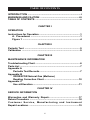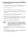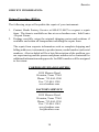
1
ODORATOR®
User’s Manual
Natural Gas (Methane)
PROPRIETARY NOTICE
The contents of this instruction manual are proprietary to the Manufacturing
Division of Heath Consultants Incorporated. Reproduction of this manual,
in whole or in part, is prohibited without the express written consent of
Heath Consultants Incorporated.
Heath Consultants Manufacturing Division operates under a continual
product improvement program and reserves the right to make improvements
and/or changes without prior notification.
This manual supersedes all previous manuals for this instrument.
COPYRIGHT 2013, HEATH CONSULTANTS INCORPORATED
MANUAL, Methane, HPN: 0715630 Rev. J
ODORATOR, Methane Complete, with case, HPN: 0705637-0
ODORATOR
®
User’s M a nual
Natural Gas (Methane)
Heath Consultants Incorporated
Houston, TX
713/844-1300
Fax: 713/844-1309
1-800-HEATH-US
www.heathus.com
Heath....Safety, Leadership, Innovation, Performance
Then, Now and Tomorrow
INTRODUCTION
Natural gas (methane) to be tested enters the ODORATOR through
the barbed fitting at the gas supply inlet port. Internally, the gas passes
through an internal five micron filter to the input of a low pressure
regulator. It then passes from the output of the low pressure regulator
to the flow metering valve. This valve, located on the top panel of
the ODORATOR, is operated by the user. After passing through the
valve (when opened), the gas enters the mass flow sensor. This is
the heart of the ODORATOR. The mass flow sensor responds to gas
flow within the range of the flow metering valve.
The signal from the mass flow sensor is then processed, converted to
a digital signal and fed to a liquid crystal display (LCD). The gas from
the mass flow sensor then passes to the mixing chamber where it is
combined with air drawn in by a blower wheel. The user then sniffs
the gas / air mixture at the exhaust port. The flow metering valve
is incrementally opened and the exhaust port sniffed until odorant
is readily detectable at which time the user presses and holds the
READ switch down to display percent gas in air by volume.
The electronics and the speed of the blower wheel are calibrated so
that the concentration of the methane gas / air sample at the exhaust
port agrees with the LCD at the 20% Lower Explosive Level (L.E.L.)
which is 1.00 % gas. All other readings may be corrected using
the correction chart. The correction chart is included to linearize
the instrument within its range. To use the chart, record both the
ODORATOR readily detectable level reading and the corrected actual
value. For ODORATOR readings not specified in the chart, linearly
interpolate between the next highest and lowest points on the chart.
Do not extrapolate beyond the readings in the chart. Depending on
how much the flow metering valve is opened, the concentration of gas
in air at the exhaust port will be anywhere from zero to approximately
2%. The LCD can only indicate up to 1.99%. Concentrations above
1.99% will be indicated by the LCD having its last two digits dashed
out as “1.--”.
i
When the ODORATOR is turned on, the user might momentarily
notice the letter “L” on the LCD when the READ switch is depressed
and held down. If the “L” fails to disappear, it may be an indication
of blower speed. The “L” indicates a speed problem, and if on, the
Odorator should not be used.
When it is time to replace the batteries, “LO BATT” will be indicated in
the upper left corner of the LCD when the READ switch is depressed
and held down.
The ODORATOR is designed and intended to be used in accordance
with the GPTC Guide For Gas Transmission And Distribution Piping
Systems, (49 CFR) 192.625 Subpart L, dated 10-15-03 and the
American Society For Testing And Materials Standard D 6273 - 08.
Supply gas must be natural gas (methane) of high quality. Blended
or mixed gases as sometimes found during peak shaving cannot be
tested using the ODORATOR.
ii
WARNINGS AND CAUTION
PRIOR TO USE, OPERATOR SHOULD READ ALL PRECAUTIONS,
I N S T R U C T I O N S F O R O P E R AT I O N , A N D M A I N T E N A N C E
R E Q U I R E M E N T S C O N TA I N E D I N P R O D U C T M A N U A L .
NOTE:
DO NOT USE THE ODORATOR OR BREATHE IN GAS
FROM SOURCES WHICH MAY CONTAIN TOXIC LEVELS
OF CHEMICALS, SUCH AS HYDROGEN SULFIDE (H 2S),
AS IT COULD BE HARMFUL TO HUMAN HEALTH AND
SAFETY TO DO SO. SOURCES WHICH MAY CONTAIN
TOXIC LEVELS OF CHEMICALS INCLUDE, BUT ARE NOT
LIMITED TO, PRODUCTION SYSTEMS AND LANDFILLS.
IT IS THE SOLE RESPONSIBILITY OF THE PRODUCT PURCHASER/
OWNER TO ENSURE THAT: (1) ALL OPERATORS AND/OR USERS OF THE
ODORATOR READ, UNDERSTAND, AND COMPLY WITH THE PRECAUTIONS,
INSTRUCTIONS FOR OPERATION, AND MAINTENANCE REQUIREMENTS
CONTAINED IN THIS MANUAL; (2) THE ODORATOR IS ONLY USED IN A
PROPER AND SAFE MANNER; AND (3) WHILE USING THE ODORATOR,
OPERATORS ARE NOT INHALING OR SNIFFING DANGEROUS MATERIALS
THAT COULD CAUSE INJURY OR DEATH.
HEATH WARRANTS ONLY THAT THE PARTS MANUFACTURED BY IT WILL
BE AS SPECIFIED AND FREE OF DEFECTS. HEATH MAKES NO OTHER
WARRANTIES OR REPRESENTATIONS OF ANY KIND WHATSOEVER,
EXPRESS OR IMPLIED, AND ANY AND ALL IMPLIED WARRANTIES
INCLUDING ANY WARRANTY OF MERCHANTABILITY AND FITNESS FOR
A PARTICULAR PURPOSE OR USE ARE HEREBY DISCLAIMED.”
DURING OPERATION, KEEP THE ODORATOR AWAY FROM OPEN FLAMES.
INLET SUPPLY PRESSURE SHOULD NOT EXCEED FOUR PSIG. INLET
PRESSURES IN EXCESS OF FOUR PSIG WOULD RUPTURE THE LOW
PRESSURE REGULATOR DIAPHRAGM, VENT THE GAS OUT OF THE
INSTRUMENT AND CAUSE AN INSTRUMENT FAILURE. THE RECOMMENDED
INLET SUPPLY PRESSURE IS 7” WATER COLUMN.
WHEN OPERATING THE ODORATOR, YOU WILL BE WORKING WITH
FLAMMABLE METHANE GAS WHICH IS POTENTIALLY DANGEROUS IF
NOT HANDLED PROPERLY. METHANE GAS FROM A LECTURE BOTTLE
MAY BE ODORLESS AND IS FLAMMABLE IN CONCENTRATIONS OF
APPROXIMATELY 5.0 TO 15.0 PERCENT BY VOLUME IN AIR.
WHEN YOU ARE NOT OPERATING THE ODORATOR, CLOSE ALL VALVES
AND TURN THE ODORATOR OFF.
iii
ANY TIME GAS IS BEING PASSED THROUGH THE ODORATOR THE POWER
SWITCH MUST BE TURNED ON. THIS WILL DILUTE THE GAS AT THE
EXHAUST PORT AND PREVENT POCKETS OF CONCENTRATED GAS FROM
ACCUMULATING.
100% L.E.L. IS APPROXIMATELY EQUAL TO 5% METHANE GAS BY VOLUME
IN AIR. AS LONG AS THE REFERENCE C.G.I. READS SAFELY BELOW THE
L.E.L., YOU SHOULD NOT HAVE ANY PROBLEM WITH A FLAMMABLE
MIXTURE BUILDING UP.
ANY SUSPICION OF A GAS LEAK BY UNEXPLAINED SOUND OR OPERATION
OF THE ODORATOR IS REASON TO IMMEDIATELY SHUT OFF THE GAS
SUPPLY VALVES AND THEN SEEK THE CAUSE.
If indoors, do not turn the ODORATOR on until a reference C.G.I. indicates the
environment is safe. Likewise, allow the ODORATOR to purge for at least one
(1) minute after a reference C.G.I. also indicates the environment is safe. The
ODORATOR is NOT DESIGNATED Intrinsically Safe and MUST NOT be used
in a confined space or hazardous location.
WARNING:
KEEP THE ODORATOR AWAY FROM OPEN FLAMES, INLET PRESSURE
SHOULD NEVER EXCEED 4 PSIG AND DO NOT OBSTRUCT OR BLOCK THE
INTAKE OR EXHAUST PORT.
CAUTION:
BECAUSE OF INHERENT LIMITATIONS, LIQUID CRYSTAL
DISPLAYS SHOULD NOT BE SUBJECTED TO EXTREMES
OF TEMPERATURE OR HUMIDITY. IF THE INSTRUMENT
IS EXPOSED TO A TEMPERATURE BELOW FREEZING OR
ABOVE +49 OC (+120 OF), THE LIQUID CRYSTAL DISPLAY
MAY TEMPORARILY CEASE TO FUNCTION PROPERLY, AND
IN SOME CASES PERMANENT DAMAGE MAY RESULT. IT
IS THEREFORE RECOMMENDED THAT THE INSTRUMENT
NOT BE SUBJECTED TO EXTREME CONDITIONS SUCH AS A
CLOSED VEHICLE IN DIRECT SUNLIGHT OR CONTINUOUS
SUB-FREEZING TEMPERATURES.
USE AT ELEVATION:
THE ODORATOR SHOULD BE USED WITHIN 1000 FEET OF
ITS CALIBRATION ELEVATION FOR ACCURACY. A READING
CORRECTION CHART, FOUND IN APPENDIX C, MAY BE USED
FOR ELEVATION CHANGES GREATER THAN 1000 FEET.
iv
TABLE OF CONTENTS
INTRODUCTION .............................................................................i
WARNINGS AND CAUTION .........................................................iii
TABLE OF CONTENTS .................................................................v
CHAPTER I
OPERATION
Instructions for Operation ...........................................................1
A. Procedures ........................................................................1
Figure 1 ...................................................................................4
CHAPTER II
Periodic Test ................................................................................5
Calibration ....................................................................................5
CHAPTER III
MAINTENANCE INFORMATION
Troubleshooting Chart .................................................................6
Parts List .......................................................................................7
Appendix A
Periodic Test Records ..........................................................7
Appendix B
ODORATOR Natural Gas (Methane)
Reading Correction Chart ..................................................10
Appendix C
Use at Elevation ..................................................................11
CHAPTER IV
SERVICE INFORMATION
Warranties and Warranty Repair........................................17
Return Procedure .......................................................................18
Customer Service, Manufacturing and Instrument
Repair Locations ..........................................................................19
v
Operation
Chapter I
OPERATION:
This Chapter discusses the proper steps to safely operate the ODORATOR.
Also included are procedures for periodic testing and identification of the
ODORATOR’s controls.
Operation of the ODORATOR
WARNING
DURING OPERATION, KEEP THE ODORATOR AWAY FROM OPEN
FLAMES. INLET SUPPLY SHOULD NOT EXCEED 4 PSIG AND 1/4
PSIG (7 INCHES WATER COLUMN) IS RECOMMENDED.
**NOTE**
Connect the ODORATOR to the gas supply with a nonabsorbing, odor-free hose such as high grade urethane,
PVC, or Tygon.
**NOTE**
Users of the ODORATOR should be selected with
due consideration to smoking habits, colds, and other
conditions of health, since these factors affect the sense
of smell. It is desirable to select operators with an
average sense of smell in order to obtain reasonably
consistent results from the use of this instrument.
**NOTE**
See Figure 1 on page 4 for reference to the following
steps.
**NOTE**
All valves must be closed and the Odorator turned “OFF”.
A. Odorization Readily Detectable Test Procedure:
1. Prior to attaching the sample hose, sniff the sample hose and verify no
odorant is detected. If so, replace the sample hose.
1
Operation
2. Connect the sample hose to the gas supply outlet valve and to the
ODORATOR inlet port (1).
3. Open the gas supply outlet valve and the ODORATOR flow metering
valve for about 10 seconds to purge the air out of the sample hose.
4. Close the flow metering valve.
5. Turn the ODORATOR “ON”. Raise the exhaust port cover.
6. Wait about 30 seconds and then position the nose about 3/4 inch (20
mm) above the exhaust port and sniff the exhaust. The exhaust must
be un-odorized.
7. Push the read switch (5) and while holding it down adjust the zero knob
(7) until the LCD reads “.00”. Release the read switch.
8. Slowly open the flow metering valve counter-clockwise 1/2 - 1 turn.
Wait about 30 seconds and then position the nose about 3/4 inch (20
mm) above the exhaust port and sniff the exhaust. Your upper lip may
lightly touch the front edge of the exhaust port.
9. If no odorant is detected in the exhaust, repeat step 8.
**NOTE**
The user should frequently pause when sniffing for
odorant by moving the nose away from the instrument,
breathing fresh air and then continuing testing. This
precaution is necessary because the sense of smell
fatigues rapidly during this type of test.
10. The first faint smell of odorant is called the threshold detection level.
Considerable variation will exist among individuals in detecting this
threshold level.
11. Slowly open the flow metering valve another 1/2 - 1 turn, wait about
30 seconds and then position the nose about 3/4 inch (20 mm) above
the exhaust port and sniff the exhaust.
2
Operation
12. If the exhaust does not have a readily detectable odor repeat step 11. If
the exhaust does have a readily detectable odor, push and hold the read
switch down and record the percent gas in air by volume reading as
shown on the LCD. This reading is the readily detectable level which
should be noticed by the average person’s sense of smell.
13. Close the gas supply outlet valve, the flow metering valve and then
disconnect the sample hose from the gas supply outlet.
14. Leave the ODORATOR “ON” for approximately one minute after the
test to purge the mixing chamber.
15. Turn the ODORATOR “OFF”.
16. If chosen, correct the reading value using the correction chart. The
correction chart is included to linearize the instrument in its range.
To use the chart, take the ODORATOR readily detectable level
reading and look up and record the corrected actual % gas value.
For ODORATOR readings not specified within the chart, linearly
interpolate between the next highest and lowest points on the chart. Do
not extrapolate beyond the readings in the chart. The readily detectable
level reading and, if chosen, the corrected actual value must meet
the requirements of the user’s company operations procedures.
Use at Elevation. See Appendix C, page 11.
3
Operation
ODORATOR
1
2 3
4
5
6
Figure 1
7
8
9
10
Side View
1
1. Gas Inlet 6. Calibration Sticker
2. Power Switch 7. Flow Metering Valve
3. Power Indicator 8. Correction Chart 4.LCD9.Fine Zero Knob
5. Read Switch 10. Exhaust Port
4
Operation
Chapter II
Periodic Test:
1. Every thirty (30) days the ODORATOR should be operated with the
power switch on and while not hooked up to a gas supply.
2. Wait about 30 seconds and then position the nose about 3/4 inch (20
mm) above the exhaust port and sniff the exhaust.
3. If no odor is detected, turn the ODORATOR “OFF”. The ODORATOR
has not absorbed the odorant and is usable.
4. If an odor is detected, turn the ODORATOR “OFF” and send it to the
nearest Heath Repair Center (Regional Office) listed on page 19. The
odor is an indication that the ODORATOR has absorbed the odorant
and must have its internal tubing replaced and gas flow components
cleaned.
The forms on pages 8 and 9 are provided to document the Periodic
Tests and are as a courtesy only. Company procedures will define how
records are kept and in what format.
Calibration:
For regulatory compliance, instrument calibration and maintenance
a factory calibration is recommended every 12-15 months from the
date of the previous factory calibration. Only Heath factory or factory trained personnel should perform ODORATOR calibration. Factory
recognized labels and seals maintain warranty.
Refer to page 19 for Heath repair and calibration centers.
5
Maintenance
Chapter III
MAINTENANCE:
Troubleshooting Chart
SYMPTOM
PROBABLE
CAUSE
“LO BATT” appears on Weak batteries.
LCD.
REMEDY
Replace batteries.
Motor and LCD will not
turn on.
RMA
Speed Indicator “L”
comes on.
RMA
LCD will not zero with Metering valve open or Close metering valve
gas supply line attached instrument problem.
or RMA.
to the ODORATOR.
Odorant
detected
always
Contaminated sample
hose or flow system
Change tubing or
RMA.
The RMA process may be found on page 18 of this manual.
6
Maintenance
Parts List
The following list specifies ODORATOR parts and accessories that are
available from the factory or regional office.
0715630
0715631
0711517
22112110
103607-0
0716725
0111004
0716893
Manual, ODORATOR User’s, Methane
Correction Chart, Methane
Battery, Alkaline “C” size
Tubing (available in various lengths), Tygon
Label, “Warning” Odorator
Regulator, External, Low Pressure, 250 PSI max.
Regulator, External, High Pressure, 3000 PSI max.
Overlay, Correction Chart
Appendix A
Periodic Test Records
The Periodic Test should be conducted every 30 days. The procedure for this
test may be found on page 5 of this manual.
The forms on pages 8 and 9 are provided for your convenience. They should
remain in the manual and be kept in a safe location as a permanent record
of periodic testing. Company procedures will define how records are kept
and in what format.
7
Appendix A
Periodic Test Record
Test Date
Results
Action
8
Operator Name
Appendix A
Periodic Test Record
Test Date
Results
Action
9
Operator Name
Appendix B
Appendix B
ODORATOR Correction Chart for Methane
This chart assumes the ODORATOR has been properly zeroed and allowed
to run for at least one minute.
Methane Correction Chart, 1.00 % Reference
ODORATOR %
Gas Reading
Actual % L.E.L.
.10
.20
.30
.40
.50
.60
.70
.80
.90
1.00 Ref.
1.10
1.20
1.30
1.40
1.50
1.4
3.4
5.0
6.6
8.0
10.0
12.4
15.0
17.4
20.0 Ref.
22.0
26.6
31.2
37.2
41.0
10
Actual % Gas
0.08
0.17
0.25
0.33
0.40
0.50
0.62
0.75
0.87
1.00 Ref.
1.10
1.33
1.56
1.81
2.05
Appendix C
Appendix C
ODORATOR Use at Elevation
The ODORATOR works by allowing a metered amount of sample gas to
mix with a fixed amount of air and the mixture is then tested by a user for
odorant detection. The internal components of the ODORATOR are very
stable over changes in elevation. The air that is mixed, however, thins out
with increasing elevation and must be accounted for. An elevation change
of 3000 feet from the calibration can produce reading discrepancies of nearly
10 % which may be corrected. It is recommended that the ODORATOR
readings be corrected whenever the elevation change from calibration is
1000 feet or more. The calibration elevation may be found on the exhaust
port label.
A correction chart with accompanying usage directions has been developed.
The chart provides corrections for both increased and decreased elevations.
Most instruments will be used at elevations higher than their calibration
elevation. ODORATORS calibrated at the factory have a calibration elevation of about 50 feet. Many gas utilities send their ODORATORS to
the Heath factory for periodic calibration, hence most instruments will be
used at elevations higher than their calibration elevation. ODORATORS
calibrated at one elevation and then used at a higher elevation will make the
most use of this chart. An ODORATOR calibrated and used within 1000
feet of the same elevation will use the respective correction chart found on
the instrument.
The elevation correction chart is based on a normal atmosphere. Abnormal atmospheres, as caused by extreme weather conditions, can affect
the measurements and safe use of the ODORATOR and operation is not
recommended. Usage instructions are included with the chart but use the
difference in elevation between the working or measurement elevation and
the calibration elevation to select the respective correction value versus the
ODORATOR’S reading.
11
Appendix C
**Note**
The elevation correction chart supports new style Methane ODORATORS only. Instruments manufactured
before July 1997, that have not been upgraded or calibrated to a methane reference other than 1.00% will not
use the elevation correction charts. Consult the factory
for using older style ODORATORS at elevation. To
identify an ODORATOR’S style or to tell if an upgrade
has been performed, check the top panel to see if there
is a snap-in bezel or a clear window in the overlay covering the display (“LCD”). Older style ODORATORS
have a snap-in bezel over the LCD. ODORATORS not
calibrated for 1.00% methane have correction charts
for that gas or reference level and can be identified by
the chart as the reading and actual values will be equal
at the reference level.
12
Appendix C
Elevation Corrections for the Methane ODORATOR
The methane ODORATOR mixes air with natural gas to allow the user to
determine the percent gas level at which odorant is readily detectable. As
elevation is increased or decreased, the air density changes and must be
accounted for. Use the Elevation Change Correction Chart as follows:
1. Use the ODORATOR to determine the readily detectable level per
the instructions in this manual.
2. Write down the readily detectable reading from the LCD on the
ODORATOR.
3. Write down the elevation at which the ODORATOR was last
calibrated as found on the label on the inside of the exhaust port
cover.
4. Determine the elevation at which the reading was taken.
5. Subtract the calibration elevation from the reading elevation and
round off to the nearest 1000’.
6. Positive elevation differences correspond to the “UP” columns in
the chart while negative elevation differences correspond to the
“DOWN” colunms. Determine which elevation change correction
chart column to be used.
7. Use the ODORATOR reading and either look up the actual % gas
value from the chosen column or interpolate the actual % gas value
for the readings between the values on the chart and write the actual
% gas value down.
Interpolation Example 1: UP Column
An ODORATOR reading of .23 is taken at 3000’. The calibration elevation
is 50’ so the elevation difference is 3000 - 50 = 2950, which is rounded
off to 3000’. The difference is positive so the UP 3000 correction column
will be used.
A reading of .23 lies between chart readings of .20 and .30. This reading
also lies between actual values of .19 and .28 using the UP 3000 correction
column.
13
Appendix C
The reading as a percentage between the adjacent chart readings can be
used to determine the actual value using the same percentage between
chart actuals.
The reading of .23 is 30% of the difference in the chart higher reading from
the chart lower reading. The lower chart reading and actual will be used as
the base or reference.
.23 - .20
.30 - .20
=
.3 or 30%
Therefore the actual value will be 30% of the difference in the chart higher
actual from the chart lower actual. Again, the lower value will be the base
or reference.
30% of (.28 - .19) = .3 x .09 = .027 which is rounded off to .03
Since the actual value base is .19, the actual value will be .19 + .03 = .22% gas.
Interpolation Example 2: DOWN Column
An ODORATOR reading of .23 is taken at 2700’. The calibration elevation is
5500’ so the elevation difference is 2700-5500 = -2800 which is rounded of to
-3000’. The difference is negative so the DOWN 3000 correction column will
be used.
A reading of .23 lies between chart readings of .20 and .30. This reading
also lies between actual values of .15 and .22 using the DOWN 3000 correction column.
The reading as a percentage between the adjacent chart readings can be
used to determine the actual value using the same percentge between chart
actuals.
The reading of .23 is 30% of the difference in the chart higher reading from
the chart lower reading. The lower chart reading and actual will be used as
the base or reference.
.23 - .20
.30 - .20
=
14
.3 or 30%
Appendix C
Therefore the actual value will be 30% of the difference in the chart higher
actual from the chart lower actual. Again, the lower value will be the base
or reference.
30% of (.22 - .15) = .3 x .07 = .021 which is rounded off to .02
Since the actual value base is .15, the actual value will be .15 + .02 = .17% gas.
15
.07
.14
.21
.28
.33
.42
.52
.63
.73
.84
.06
.14
.20
.26
.32
.40
16
.49
.60
.69
.80
.88
.76
.66
.54
.44
.35
.29
.22
.15
.07
.92
.80
.69
.57
.46
.37
.30
.23
.16
.07
.96
.83
.72
.59
.48
.38
.32
.24
.16
.08
Down Down Down Down Down
5,000’ 4,000’ 3,000’ 2,000’ 1,000’
.87
.75
.62
.50
.40
.33
.25
.17
.08
A
C
T
U
A
L
1.03
.90
.78
.64
.52
.41
.34
.26
.18
.08
1.07
.93
.80
.66
.53
.43
.35
.27
.18
.09
1.10
.96
.83
.68
.55
.44
.36
.28
.19
.09
1.14
.99
.85
.70
.57
.45
.37
.28
.19
.09
1.17
1.02
.88
.73
.59
.47
.39
.29
.20
.09
1.20
1.04
.90
.74
.60
.48
.40
.30
.20
.10
1.23
1.07
.92
.76
.62
.49
.41
.31
.21
.10
1.26
1.09
.94
.78
.63
.50
.42
.31
.21
.10
1.29
1.12
.96
.80
.64
.51
.42
.32
.22
.10
1.31
1.14
.98
.81
.66
.53
.43
.33
.22
.11
Up
Up
Up
Up
Up
Up
Up
Up
Up
Up
1,000’ 2,000’ 3,000’ 4,000’ 5,000’ 6,000’ 7,000’ 8,000’ 9,000’ 10,000’
Instructions for correction on page 13
1.00 1.00
.90
.80
.70
.60
.50
.40
.30
.20
.10
R
E
A
D
I
N
G
Elevation Change Correction Chart
Appendix C
Service
Chapter IV
SERVICE INFORMATION:
Warranties and Warranty Repair
All instruments and products manufactured by Heath Consultants
Incorporated are warranted to be free from defects in material and
workmanship for one (1) year from the date of shipment.
Furthermore, the warranty on authorized repairs in the Houston Factory
Service Center (FSC) and other regions is ninety (90) days materials and
thirty (30) days labor. This repair warranty does not extend any other
applicable warranties.
Our warranty covers only failures due to defects in materials or workmanship
which occur during normal use. It does not cover failure due to damage
which occurs in shipment, unless due to improper packing, or failures which
result from accident, misuse, abuse, neglect, mishandling, misapplication,
alteration, modification, or service by anyone other than a Heath warranty
repair location.
Batteries and damage from battery leakage and all expendable items such
as filters and tubing are excluded from this warranty.
Heath’s responsibility is expressly limited to repair or replacement of any
defective part, provided the product is returned to an authorized warranty
repair location, shipped prepaid, and adequately insured. Return shipping
charges and insurance will be paid by Heath warranty expense.
We do not assume liability for indirect or consequential damage or loss of
any nature in connection with the use of any Heath product. There are no
other warranties expressed, implied, or written except as listed above.
17
Service
SERVICE INFORMATION:
Return Procedure (RMA):
The following steps will expedite the repair of your instrument:
1. Contact Heath Factory Service at 800-432-8487 to request a repair
form. The form is available on-line at www.heathus.com - InfoCenter
- Repair Forms.
2. Package carefully, using the original shipping carton and cushions if
available and return all components including the repair form.
The repair form requests information such as complete shipping and
billing addresses, instrument or product name, model number and serial
numbers. Also included will be a brief description of the problem you
are experiencing and the person and phone number to be contacted for
additional information and approvals. An RMA number will be assigned
to the return.
CORPORATE HEADQUARTERS
9030 Monroe Road
Houston, Texas 77061
Phone: 713-844-1300
Fax: 713-844-1309
www.heathus.com
FACTORY SERVICE
9030 Monroe Road
Houston, Texas 77061
Phone: 713-844-1350
Fax: 713-844-1384
www.heathus.com
[email protected]
18
Service
SALES, CUSTOMER SERVICE, AND INSTRUMENT REPAIR
National Toll Free # 1-800-HEATH-US (1-800-432-8487)
REGIONAL SALES, CUSTOMER SERVICE, AND INSTRUMENT
REPAIR
Eastern Region
Heath Consultants Incorporated
575 Park Way
Monongahela, PA 15063
Phone: 724-242-3145
Fax: 724-872-3206
Southwest Region
Heath Consultants Incorporated
9030 Monroe Road
Houston, TX 77061
Phone: 713-844-1300
Fax: 713-844-1309
Western Region
Heath Consultants Incorporated
30 Main Avenue, Unit 3
Sacramento, CA 95838
Phone: 916-921-5198
Fax: 916-921-5437
19
Service
NOTES
20
Service
NOTES
21
Heath Consultants Incorporated operates under a continual product improvement program and
reserves the right to make improvements and/or changes without prior notification.
Heath Consultants Incorporated
Houston, TX
713-844-1300
Fax: 713-844-1309
1-800-HEATH-US
www.heathus.com
Heath...Safety, Leadership, Innovation, Performance
Then, Now and Tomorrow