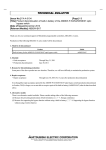
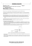
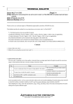
1
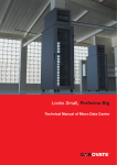
TECHNICAL BULLETIN
[Issue No.] FA-A-0018-A
[Title] Recommendation of preventive maintenance and
inspection for MELSEC programmable controllers
[Relevant Models] All MELSEC programmable controllers
[Page] 1/6
[Date of Issue] Mar. ‘08
Thank you for your continued support of Mitsubishi programmable controllers, MELSEC series.
We summarized the concept on the life and preventive maintenance of the programmable controller for planned execution of
preventive maintenance.
1. Useful life of the programmable controller
The standard useful life of the programmable controller, excluding limited life parts (aluminum electrolytic capacitor,
relay, switch, battery, fuse, etc.) is ten years.
Note that the useful life is a duration in which the programmable controller can perform proper functions/performance.
2. Necessity of preventive maintenance
The recommended replacement cycle as part of preventive maintenance is five years for modules using aluminum
electrolytic capacitor as an important part, and from five to ten years for other modules.
The programmable controller consists of various electronic components, and can perform the best functions and
performance by operating them normally. To achieve it, finding a sign of programmable controller failure early by
daily/periodic inspections and taking the corrective action are required. Especially, limited life parts cannot be used
indefinitely. Using them exceeding the years specified according to each part type (useful life) may affect the
characteristics of programmable controller, resulting in a malfunction or a failure of the devices.
Particularly, when aluminum electrolytic capacitor life ends, the noise durability lowers due to capacity low or the
printed-circuit board is damaged due to liquid leak, resulting in an erroneous input or output or a malfunction of the
programmable controller.
An aim of preventive maintenance is to prevent a device failure as far as possible by replacing parts/modules in every
certain period.
HEAD OFFICE : TOKYO BUILDING, 2-7-3 MARUNOUCHI, CHIYODA-KU, TOKYO 100-8310, JAPAN
NAGOYA WORKS : 1-14, YADA-MINAMI 5-CHOME, HIGASHI-KU, NAGOYA, JAPAN
TECHNICAL BULLETIN
[Issue No.] FA-A-0018-A
[Title] Recommendation of preventive maintenance and
inspection for MELSEC programmable controllers
[Relevant Models] All MELSEC programmable controllers
[Page] 2/6
[Date of Issue] Mar. ‘08
3. Years of use and failure occurrence
Generally, the failure rate of electronic device such as programmable controller is expressed by bathtub curve as Figure 1.
The curve is divided into the three stages: initial failure, random failure, and wear-out failure.
Wear-out
failure period
Random failure period
Failure rate
Initial failure
period
tb
ta
Years of use
Figure 1 Relationship between years of use and failure rate
Initial failure occurs during initial operation, which includes faulty part and a defect in manufacture found after first use of
the product. We make every effort to prevent the initial failure by pre-shipment test.
Random failure is unexpected and accidental failure that occurs before deterioration or wear proceeds within useful life of
the device. It is named after its eventuality from the viewpoint of statistics and genesis phenomenon. Handle the failure by
corrective maintenance; that is, preparing spare parts.
Wear-out failure occurs at the end of useful life as a result of deterioration or wear, and failure rate in this period drastically
increases as the elapse of the time. We recommend replacing our programmable controller within every ten years (rough
guide), which corresponds to the point at tb on Figure 1.
HEAD OFFICE : TOKYO BUILDING, 2-7-3 MARUNOUCHI, CHIYODA-KU, TOKYO 100-8310, JAPAN
NAGOYA WORKS : 1-14, YADA-MINAMI 5-CHOME, HIGASHI-KU, NAGOYA, JAPAN
TECHNICAL BULLETIN
[Issue No.] FA-A-0018-A
[Title] Recommendation of preventive maintenance and
inspection for MELSEC programmable controllers
[Relevant Models] All MELSEC programmable controllers
[Page] 3/6
[Date of Issue] Mar. ‘08
4. Limited life parts and preventive maintenance
Limited life parts used with our programmable controller are aluminum electrolytic capacitor, relay, switch, battery, and
fuse, etc.
(1) Aluminum electrolytic capacitor
An aluminum electrolytic capacitor is used with various modules such as power supply module.
Operating ambient temperature affects a life of the aluminum electrolytic capacitor. According to “Arrhenius law
(10 double rule)”, when the temperature increases by 10 , the life shortens to half. Meanwhile, when the
temperature decreases by 10 , the life lengthens to twice.
Life (logarithmic scale)
2L
L
0.5L
T-10
T
T+10
Temperature (
)
Figure 2 Arrhenius law
The aluminum electrolytic capacitor used with our programmable controller is designed to satisfy around 10-year life
under an environment of average ambient temperature of 40 .
However, the following preventive maintenance/maintenance and inspection are recommended, according to
achievements in the market, operating environment, and application of the aluminum electrolytic capacitor.
HEAD OFFICE : TOKYO BUILDING, 2-7-3 MARUNOUCHI, CHIYODA-KU, TOKYO 100-8310, JAPAN
NAGOYA WORKS : 1-14, YADA-MINAMI 5-CHOME, HIGASHI-KU, NAGOYA, JAPAN
TECHNICAL BULLETIN
[Issue No.] FA-A-0018-A
[Title] Recommendation of preventive maintenance and
inspection for MELSEC programmable controllers
[Relevant Models] All MELSEC programmable controllers
[Page] 4/6
[Date of Issue] Mar. ‘08
1) Power supply module
Since the aluminum electrolytic capacitor is used for smoothing 100/200V and 5V output, replace the module in
every five years (rough guide) as part of periodic preventive maintenance.
When the aluminum electrolytic capacitor life ends, the power supply may become unstable, resulting in a
malfunction of the programmable controller.
2) CPU module and I/O module
Since the aluminum electrolytic capacitor is mainly used for eliminating ripple noise, replace the module in every
five to ten years (rough guide) as part of periodic preventive maintenance.
When the aluminum electrolytic capacitor life ends, noise durability lowers due to capacity low or the
printed-circuit board is damaged due to liquid leak, resulting in an erroneous input or output or a malfunction.
Due to the reason described 1) above, replace the CPU module with power supply module in every five years
(rough guide).
3) Other modules such as special function module or intelligent function module
Since the aluminum electrolytic capacitor is mainly used for eliminating ripple noise, replace the module in every
five to ten years (rough guide) as part of periodic preventive maintenance.
When the aluminum electrolytic capacitor life ends, noise durability lowers due to capacity low or the
printed-circuit board is damaged due to liquid leak, resulting in a malfunction of the programmable controller.
In some cases, the aluminum electrolytic capacitor is used for smoothing internal power supply (example: analog
output module, positioning module, and network module (including remote I/O). Replace these modules in every
five years (rough guide) as part of periodic preventive maintenance.
HEAD OFFICE : TOKYO BUILDING, 2-7-3 MARUNOUCHI, CHIYODA-KU, TOKYO 100-8310, JAPAN
NAGOYA WORKS : 1-14, YADA-MINAMI 5-CHOME, HIGASHI-KU, NAGOYA, JAPAN
TECHNICAL BULLETIN
[Issue No.] FA-A-0018-A
[Title] Recommendation of preventive maintenance and
inspection for MELSEC programmable controllers
[Relevant Models] All MELSEC programmable controllers
[Page] 5/6
[Date of Issue] Mar. ‘08
(2) Relay (contact)
The life of the output module of contact output type depends on worn-out status of a contact.
There are two types of the life: mechanical life depending on the number of switching times and electrical life relying
on switching current value and inductance of the load (L). Figure 3 shows the typical electrical life curve. For details,
refer to User’s Manual of each module.
Generally, when switching the rated current, the electrical life becomes shorter than mechanical life. If considering
the life, suppress the maximum switching frequency within 3600 times/hour.
Replace the modules before the relay life ends as part of periodic preventive maintenance.
Example
QY10
QY18A
200
100
70
Switching life (10,000 times)
50
30
20
10
7
DC30V =0ms
5
DC100
=7ms
AC100V cos =0.7
AC200V cos =0.7
3
(L/R): Time constant
cos
: Power factor
AC100V cos =0.35
AC200V cos =0.35
DC24V =7ms
2
AC120V cos =0.2
AC240V cos =0.2
1
0.1
0.2
0.3
0.5
0.7
1
2
3
5
Switching current (A)
Figure 3 Electrical life of a relay
HEAD OFFICE : TOKYO BUILDING, 2-7-3 MARUNOUCHI, CHIYODA-KU, TOKYO 100-8310, JAPAN
NAGOYA WORKS : 1-14, YADA-MINAMI 5-CHOME, HIGASHI-KU, NAGOYA, JAPAN
TECHNICAL BULLETIN
[Issue No.] FA-A-0018-A
[Title] Recommendation of preventive maintenance and
inspection for MELSEC programmable controllers
[Relevant Models] All MELSEC programmable controllers
[Page] 6/6
[Date of Issue] Mar. ‘08
(3) Switch
Parts with contact used for the programmable controller such as a switch and socket may cause poor contact
depending on the operating environment.
Under an environment where dust and oil mist is subject to enter, foreign material may attach on the contact surface.
Under an environment where corrosive gas exists, chemical film may be generated on the contact surface. This may
cause poor contact of the contact.
Moreover, under an environment where structural parts inside the switches are under a load due to such as a
temperature, humidity, vibration, and shock, the internal mechanical precision may not be retained, resulting in poor
contact of the contact.
To prevent a malfunction due to poor contact, replace the modules in every ten years (rough guide) as part of periodic
preventive maintenance.
(4) Battery
Built-in batteries of the CPU module, special function module, and intelligent function module are used to back up
(power failure compensation) the memories storing programs, parameters, and control data in case of power-off or
power failure.
The battery life depends on module type.
A battery error occurs when battery capacity lowers and a voltage is equal to or less than the specified value. Since
there is the retention time from several tens to hundred hours after battery error, replace the battery within the time.
For checking method of battery errors, refer to User’s Manual of each module.
(5) Fuse
Fuse is used to protect the input side of power supply module and the external output element of output module.
Especially when the output module is AC load, some loads causes inrush current reaching several to 10 times higher
than the rated load current, and an element fatigues, resulting in fuse blown. The value, frequency, and number of
occurrences of inrush current affect its life.
A spare fuse is attached to our programmable controller to which a fuse can be replaced. Even if a fuse is not blown,
replace the fuses or modules in every ten years (rough guide) as part of periodic preventive maintenance.
5. When the programmable controller system has not been used for a long period of time
To prevent accidents such as electric leakage due to the end of service life or deterioration or insulation failure, be sure to
turn off the power of the programmable controller system if it will not be used for a long period of time.
6. Module replacement before the end of service life
Before the expected service life is reached, consider replacing your programmable controller module with a new one or the
latest series module as preventive maintenance.
7. Other information
To shorten recovery time required for programmable controller failure, preparing spare parts is recommended.
For inspection, contact your local Mitsubishi sales office or representative. For items and descriptions of daily/periodic
inspections, refer to User’s Manual of each module.
HEAD OFFICE : TOKYO BUILDING, 2-7-3 MARUNOUCHI, CHIYODA-KU, TOKYO 100-8310, JAPAN
NAGOYA WORKS : 1-14, YADA-MINAMI 5-CHOME, HIGASHI-KU, NAGOYA, JAPAN