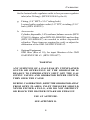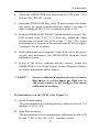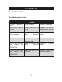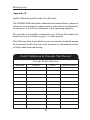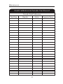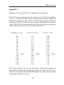
1
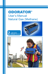
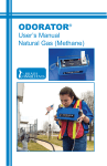
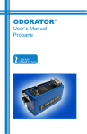
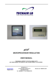
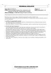
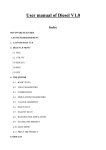
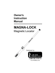
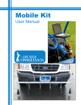
ODORATOR®
User’s Manual
PROPRIETARY NOTICE
The contents of this instruction manual are proprietary to the
Manufacturing Division of Heath Consultants Incorporated.
Reproduction of this manual, in whole or in part, is prohibited
without the express written consent of Heath Consultants
Incorporated.
Heath Consultants Manufacturing Division operates under a
continual product improvement program and reserves the right
to make improvements and/or changes without prior
notification.
This manual supersedes all previous manuals for this
instrument.
COPYRIGHT 2002, HEATH CONSULTANTS INCORPORATED
HPN. MANUAL: 0715630 Rev. C
HPN. ODORATOR Complete Unit: 0705637
ODORATOR
®
User ’s Manual
Heath Consultants Incorporated
Houston, TX
713/844-1300
Fax: 713/844-1309
1-800-HEATH-US
www.heathus.com
Heath....Leadership, Innovation, Performance
Then, Now and Tomorrow
INTRODUCTION
Natural Gas (Methane) to be analyzed enters the
ODORATOR through the barbed fitting at the gas supply
intake port. Internally, the gas passes through an internal five
micron filter to the input of a low pressure regulator. It then
passes from the output of the low pressure regulator to the
flow valve. This valve, located on the front panel of the
ODORATOR, is operated by the user. After passing through
the valve (when opened) the gas enters the mass flow sensor.
This is the heart of the ODORATOR. The mass flow sensor
responds to gas flow within the range of the flow valve.
The signal from the mass flow sensor is then processed,
converted to a digital signal, and fed to a liquid crystal display
(LCD). The gas from the mass flow sensor then passes to
the mixing chamber assembly where it is combined with air
drawn in by a blower motor and impeller. The operator then
samples the gas/air mixture at the exhaust sniffing port.
When odorant is detected, the operator presses the READ
switch to display percent natural gas.
The electronics and the speed of the blower motor are
calibrated so that the concentration of the gas/air sample at
the exhaust port agrees with the LCD at the 20% Lower
Explosive Level (L.E.L.) which is 1% gas. All other values
must be corrected using the chart. The correction chart is
included to linearize the instrument in its range. To use the
chart, record both the ODORATOR reading and the corrected
reading. For ODORATOR readings not specified in the chart,
linearly interpolate between the next highest and lowest points
on the chart. Do not extrapolate beyond the readings on the
chart. Depending on how much the valve is opened, the
concentration of gas/air at the blower exhaust port will be
anywhere from zero to approximately 2.50%. The LCD
i
can only read to 1.99%. Concentrations above 1.99% will be
indicated by the LCD having its last two digits blanked out as
“1.--”.
When the ODORATOR is turned on, the operator might
momentarily notice the letter “L” on the LCD when the READ
switch is depressed. If the “L” fails to disappear, it may
indicated insufficient blower speed, such as would occur if
the motor and impeller weren’t turning at all or too slowly.
The “L” indicates low blower speed.
When it is time to replace the batteries, “LO BATT” will be
indicated in the upper left corner of the LCD when the READ
switch is depressed.
ii
WARNINGS AND CAUTION
IT IS ESSENTIAL THAT USERS OF THIS INSTRUMENT READ,
UNDERSTAND, AND FOLLOW THE INSTRUCTIONS FOR OPERATION
AND MAINTENANCE AND THE PRECAUTIONS CONTAINED IN THIS
MANUAL TO INSURE THE INSTRUMENT IS USED IN A PROPER AND
SAFE MANNER.
DURING OPERATION, KEEP THE ODORATOR AWAY FROM OPEN
FLAMES. INLET SUPPLY PRESSURE SHOULD NOT EXCEED FOUR
P.S.I.G. INLET PRESSURES IN EXCESS OF FOUR P.S.IG. WOULD
RUPTURE THE LOW PRESSURE REGULATOR DIAPHRAGM WHICH
WOULD VENT THE GAS OUT OF THE INSTRUMENT AND CAUSE AN
INSTRUMENT FAILURE.
WHEN CALIBRATING THE ODORATOR, YOU WILL BE WORKING
WITH FLAMMABLE GAS (NORMALLY METHANE GAS) WHICH IS
POTENTIALLY DANGEROUS IF NOT HANDLED PROPERLY.
METHANE GAS FROM A LECTURE BOTTLE MAY BE ODORLESS AND
IS FLAMMABLE IN CONCENTRATIONS OF APPROXIMATELY 5.0 TO
15.0 PERCENT BY VOLUME IN AIR.
WHEN YOU ARE NOT CALIBRATING OR OPERATING THE
ODORATOR, CLOSE ALL VALVES AND TURN THE ODORATOR OFF.
ANY TIME GAS IS BEING PASSED THROUGH THE ODORATOR THE
POWER SWITCH MUST BE TURNED ON. THIS WILL DILUTE THE
GAS AT THE BLOWER EXHAUST AND PREVENT POCKETS OF GAS
ACCUMULATING.
100% L.E.L. IS APPROXIMATELY EQUAL TO 5% METHANE GAS BY
VOLUME IN AIR. AS LONG AS THE C.G.I. READS BELOW THIS YOU
SHOULD NOT HAVE ANY PROBLEM WITH A FLAMMABLE MIXTURE
BUILDING UP.
ANY SUSPICION OF A GAS LEAK BY UNEXPLAINED SOUND OR
OPERATION OF THE ODORATOR IS REASON TO IMMEDIATELY
SHUT OFF THE GAS SUPPLY VALVES AND ODORATOR POWER
SWITCH, THEN SEEK THE CAUSE.
iii
DURING CALIBRATION, KEEP THE ODORATOR AWAY FROM OPEN
FLAMES, INLET PRESSURE SHOULD NEVER EXCEED 4 P.S.I.G., AND
DO NOT OBSTRUCT OR BLOCK THE BLOWER INTAKE OR EXHAUST.
CAUTION:
BECAUSE OF INHERENT LIMITATIONS, LIQUID
CRYSTAL DISPLAYS SHOULD NOT BE SUBJECTED TO
EXTREMES OF TEMPERATURE OR HUMIDITY. IF THE
UNIT IS EXPOSED TO A TEMPERATURE BELOW
FREEZING OR ABOVE +49âC (+120âF), THE LIQUID
CRYSTAL DISPLAY MAY TEMPORARILY CEASE TO
FUNCTION PROPERLY, AND IN SOME CASES
PERMANENT DAMAGE MAY RESULT. IT IS
THEREFORE RECOMMENDED THAT THE
INSTRUMENT NOT BE SUBJECTED TO EXTREME
CONDITIONS SUCHASACLOSED VEHICLE IN DIRECT
SUNLIGHT OR CONTINUOUS SUB-FREEZING
TEMPERATURES.
USEATALTITUDE:
THE ODORATOR MUST BE USED WITHIN 1000 FEET
OF ITS CALIBRATION ALTITUDE FOR ACCURACY.
READING CORRECTION CHARTS, AS FOUND IN
APPENDIX D, MUST BE USED FOR ALTITUDES
GREATER THAN 1000 FEET.
iv
TABLE OF CONTENTS
INTRODUCTION .......................................................
WARNINGS AND CAUTION .....................................
TABLE OF CONTENTS .............................................
CHAPTER I
OPERATION
Instructions for Operation ..........................................
A. Procedures .....................................................
Periodic Test ..............................................................
Front Panel
Figure 1 ...............................................................
CHAPTER II
CALIBRATION
Field Calibration Procedure .......................................
A. Required Equipment ......................................
B. Procedures ....................................................
Potentiometers On The PCB ......................................
A. Speed Potentiometer ......................................
B. Span Potentiometer ........................................
C. (Coarse) Zero Potentiometer .........................
D. Flow Potentiometer ........................................
Potentiometer Location
Figure 2 ...............................................................
Field Calibration System
Figure 3 ...............................................................
v
CHAPTER III
MAINTENANCE INFORMATION
Troubleshooting Chart ...............................................
Parts List ...................................................................
Appendix A
Alternate Test Method ........................................
Appendix B
Field Calibration & Periodic Test Records ..........
Appendix C
ODORATOR Natural Gas Calibration Chart .......
Appendix D
Use at Altitude....................................................
CHAPTER IV
SERVICE INFORMATION
Warranties and Warranty Repair ...............................
Customer Service, Manufacturing and Instrument
Repair Locations........................................................
Notes .........................................................................
vi
OPERATION
Chapter I
OPERATION:
This Chapter discusses, in detail, the proper steps to safely operate
the ODORATOR. Also included are procedures for periodic testing,
and identification of the ODORATOR’s controls.
Operation of the ODORATOR
WARNING
DURING OPERATION, KEEP THE ODORATOR AWAY
FROM OPEN FLAME. INLET SUPPLY SHOULD NOT
EXCEED 4 P.S.I.G.
**NOTE**
Connect the ODORATOR to the gas supply
with a non-absorbing, odor-free hose such as
high grade urethane, PVC, or Tygon.
**NOTE**
Operators of the ODORATOR should be
selected with due consideration to smoking
habits, colds, and other conditions of health,
since these factors affect the sense of smell.
It is desirable to select operators with an
average sense of smell in order to obtain
reasonably consistent results from the use of
this instrument.
**NOTE**
See Figure 1 on page 4 for reference to the
following steps.
A. Procedures
**NOTE**
See Appendix A for Alternate Test Method.
1. Connect the sample hose to the gas supply outlet valve and to
the ODORATOR inlet port.(1)
1
OPERATION
2. Gently, turn the flow valve(6) clockwise until closed.
3. Turn the power switch(2) to “on” position.
4. Open the gas supply outlet valve.
5. For new instruments turn the flow valve(6) counter-clockwise
fully to open the valve. This will condition the ODORATOR
system. Wait for about 30 seconds or until you smell an odor
of gas at the blower exhaust, which ever occurs first, then
immediately turn the flow valve clockwise to fully close the
valve.
6. Push the read switch(5) and while holding it down adjust the
zero knob(7) until the LCD reads “.00”. Release the read switch.
7. Sniff the un-odorized air stream at the exhaust port.
8. Slowly open the flow valve counter-clockwise while sniffing
with your nose directly over the blower exhaust port
approximately 3/4”. Your upper lip should lightly touch the front
edge of the blower exhaust port.
9. When a change in odor, or first faint smell of gas is detected,
stop turning the flow valve and push the read switch. Make a
note of the percent gas reading shown on the LCD(4). This is
the threshold limit value or threshold value. Considerable variation
will exist between individuals in detecting this threshold value.
The correction chart is included to linearize the instrument in its
range. To use the chart, take the ODORATOR reading and
look up the corrected reading. For ODORATOR readings not
specified on the chart, linearly interpolate between the next highest
and lowest points on the chart. Do not extrapolate beyond the
readings on the chart.
**NOTE**
The operator should frequently pause when
sniffing for odorant, moving the nose away
2
OPERATION
from the instrument, breath fresh air, then continue the test.
This precaution is necessary because the
sense of smell fatigues rapidly during this type
of test.
10. Close the gas supply valve.
11. Disconnect the sample hose from the gas supply outlet.
12. Fully open the flow adjustment valve counterclockwise and
leave the ODORATOR on for approximately one minute after
the test to purge the mixing chamber.
13. Turn the ODORATOR off.
Periodic Test
A. Every thirty days the ODORATOR should be operated with
the power switch on and while not hooked up to a gas supply.
B. Sniff the exhaust port (Inhale normally through your nose).
C. If no odor is detected, turn the ODORATOR off. The
ODORATOR has not absorbed the odorant.
D. If an odor is detected, turn the ODORATOR off and send it to
the nearest Heath Repair Center (Regional Office) listed on
page 27. The odor is an indication that the ODORATOR has
absorbed the odorant and must have its internal tubing replaced
and gas flow components purged.
3
OPERATION
ODORATOR Top Panel
1
2
3
4
5
7
6
8
Figure 1
1. Gas Inlet
5. Read Switch
2. Power Switch
6. Flow Adjust Valve
3. Power Indicator
7. Fine Zero
4. LCD
8. Blower Exhaust
4
OPERATION
Chapter II
CALIBRATION:
Field Calibration Procedure
A. Required Equipment
1. Field Calibration Test Kit
Includes items a - i listed below:
(HPN 0727675)
a. Lecture Bottle
99.9% methane (CH4), balance zero air, refillable.
(HPN 0123519)
b. Regulator, high pressure
Lecture bottle type, used to lower lecture bottle pressure
to 10 p.s.i.g., ! 1 p.s.i.g. (HPN 0111004)
c. Regulator, low pressure
Low pressure type, used to lower lecture bottle pressure
to 10 p.s.i.g. outlet pressure to seven inches of water
column. (HPN 0716725)
d. Combustible Gas Indicator (C.G.I.)
Dual scale type 100% L.E.L. scale plus a 10% L.E.L.
scale. GMI GASURVEYOR #3 calibrated for methane is
included. (HPN 22012220)
e. Adapter
Blower exhaust port on the ODORATOR. This is the outlet
sample point for the above C.G.I. (HPN 0716773)
f.
Tubing
Blower exhaust adapter to the C.G.I. inlet (2ft long) and
5
CALIBRATION
for the lecture bottle regulator outlet to low pressure regulator
inlet (also 2ft long). (HPN 8301846 by the ft)
g. Fitting, (1/8” MPT x 3/16” tubing barb)
Lecture bottle regulator outlet (1/8” FPT) to tubing (3/16”
barb) (HPN 8300323)
h. Accessories
Cylinder, disposable, 1.0% methane, balance zero air. (HPN
0716831) Adapter valve (HPN 09140000200) and test bag
(HPN 09140009607) are needed to utilize disposable
cylinders. These items are required to verify or adjust the
calibration of the GMI GASURVEYOR #3.
i.
Optional Equipment
GMI filter (Box of 10), for input filtration of the GMI
GASURVEYOR #3. (HPN 22210077)
WARNING
ANY SUSPICION OF A GAS LEAK BY UNEXPLAINED
SOUND OR OPERATION OF THE ODORATOR IS
REASON TO IMMEDIATELY SHUT OFF THE GAS
SUPPLY VALVES AND ODORATOR POWER SWITCH,
THEN SEEK THE CAUSE.
DURING CALIBRATION, KEEP THE ODORATOR AWAY
FROM OPEN FLAMES, INLET PRESSURE SHOULD
NEVER EXCEED 4 P.S.I.G., AND DO NOT OBSTRUCT
OR BLOCK THE BLOWER INTAKE OR EXHAUST.
USE AT ALTITUDE.
SEE APPENDIX D.
6
CALIBRATION
B. Procedure
1. Calibrate or verify the accuracy of the C.G.I. with 1% (20%
L.E.L.) methane balance air mixture on the 100% L.E.L. scale.
**NOTE**
Set up the field calibration system using
Figure 3 on page 10 as your guide, with all
valves and power turned “OFF”. See Figure
1 on page 4 for the location of the top panel
controls.
2. Turn the C.G.I. on and adjust the instrument to zero on the
100% L.E.L. scale. Turn the ODORATOR power switch to
the “ON” position. Push the “ READ” switch and hold it down.
Note that the low air indicator “L” on the LCD may be on.
3. Open the valve on the 99% methane gas lecture bottle. Open
the valve at the outlet of the low pressure regulator. Observe
the ODORATOR LCD. The reading should settle and not
change (if it doesn’t, go to Step 12). Release the “READ”
switch.
4. Open the ODORATOR flow valve a few turns counterclockwise.
5. If needed, adjust the low pressure regulator to read seven inches
of water column. Also, if needed, adjust the lecture bottle
regulator to read ten p.s.i.g. on its output gauge.
6. Close the ODORATOR flow valve by turning it clockwise until
it stops. DO NOT FORCE IT.
7. Push the ODORATOR “READ” switch and hold it down. The
low air indicator “L” on the LCD should not be displayed (if it
is go to Step 12).
7
CALIBRATION
8. Adjust the ODORATOR zero knob until the LCD reads “.00”.
Release the “READ” switch.
9. Open the ODORATOR flow valve 10 turns counter-clockwise
and adjust the speed potentiometer(see figure 2 on page 9)
until a reading of 20% L.E.L is indicated on the C.G.I.
10. Push the ODORATOR “READ” switch and hold it down. The
LCD should read “1.00”. If it does not, adjust the Span
potentiometer until the LCD reads “1.00”. The Span
potentiometer is located on the internal main PCB (see Figure
2 on page 9 for its location).
11. Field calibration is now complete. Turn off all valves, the power
switch, and disconnect the ODORATOR from the field
calibration system.
12. If any of the above readings are not correct, return the
ODORATOR to the Heath Repair Center (Regional Office)
for further adjustment and/or repairs.
**NOTE**
Factory calibration requires the use of a mass
flow meter to set the input gas flow rate to
150 sccm relative to air (using a flow meter
calibrated to air flow).
Potentiometers on the PCB (See Figure 2)
A. Speed Potentiometer
This potentiometer is set during factory calibration for a C.G.I
reading of 20% L.E.L.
B. Span Potentiometer
This potentiometer is set during factory calibration for the LCD
to read “1.00” at the 20% L.E.L. reference point.
8
CALIBRATION
C. (Coarse) Zero Potentiometer
This potentiometer is set to work in conjunction with the “FINE
ZERO” control on the front panel, this control should NOT be
changed.
D. Flow Potentiometer
This potentiometer is factory set to detect a slow or stalled
blower motor. This adjustment does not affect the calibration
and will set the point where the LCD “L” comes on.
Potentiometer Location
1
3 *
2
4
5
Figure 2
1. Flow
3. T1* (1, 2 ,3, 4 from l-r)
2. Zero
4. Span
5. Speed
*Factory Jumpers: Installing jumpers on T1 pins 1 to 2 and T1 pins 3
to 4 will enable the LCD for calibration purposes only.
9
CALIBRATION
Field Calibration System
(HPN 0727675)
Low Pressure
Regulator
High Pressure
Regulator
Calibration
Adapter
Potentiometer
Locations (See
Fig. 2)
Lecture Bottle,
99.9% CH4
1
Blower
Exhaust
Port
Gauge, 7”
Water
Column
C.G.I.
Figure 3
Setup
Valve
**NOTE**
Factory calibration requires the use of a mass
flow meter to set the input gas flow rate to
150 sccm relative to air (using a flow meter
calibrated to air flow).
10
CALIBRATION
C h a p t e r III
MAINTENANCE:
Troubleshooting Chart
SYMPTOM
PROBABLE
CAUSE
“LO BATT” appears on Weak batteries.
LCD.
REMEDY
Replace batteries.
Motor and LCD will not Weak batteries or fuse Replace batteries,
replace fuse; inspect
turn on.
blown.
wiring.
LCD turns on but M o t o r l e a d s m a y Connect
have
b e c o m e leads.
motor does not.
disconnected.
motor
Low Air Indicator “L” Leads to blower may Connect
comes on.
have
become leads.
disconnected.
blower
LCD will not zero with Leads on sensor may Connect
become leads.
gas
supply
line have
attached
to
the disconnected.
ODORATOR.
sensor
LCD will not zero with
gas supply line
attached to the
ODORATOR.
Leaky flow valve in “off” Replace flow valve
and recalibrate.
position.
11
MAINTENANCE
Parts List
The following list specifies ODORATOR assemblies and specific
parts that are available from the factory or Regional Office for
repair or replacement purposes.
*
*
*
*
*
*
*
*
*
*
*
*
*
*
*
0715626
0715627
0715628
0715664
0715805
0715686
0715630
0715631
0715632
0711517
0715826
0715813
0715822
0715834
0715835
0715842
0715843
0715814
0110679
0717451
0817090
0715685
0715825
8307484
0715668
0715669
0715868
0715687
0715690
0715820
ASSY, TOP PANEL
ASSY, CHASSIS
PCB, MAIN ASSY
ASSY, BLOWER
ASSY, SAMPLING HOSE
ASSY, FLOW SENSOR
MANUAL, ODORATOR USER’S
CALIBRATION CHART, METHANE
FILTER, IN-LINE, 5 MICRON
Battery, Alkaline “C” size
Tubing (available in various lengths)
Zero Potentiometer, 10 turn
Knob, black
Guard, READ switch
Button, black, READ switch
Spring, Exhaust
Spring, Intake
Regulator, Internal Low Pressure
“O” Ring, Seal, Regulator Adapter
Motor, Blower
Switch, power “ON/OFF”
Switch, push-button, READ
Wheel, Blower
Screw, 6-32 x 2.25” long (Housing)
Fuseholder, In-line
Fuse, AGC fast blow, 1 amp
Valve, Flow, Stainless Steel
Cartridge, replacement for 0715868
LCD
Label Instructions
12
MAINTENANCE
*
*
0715859
0715925
0715926
0716893
ASSY, BATTERY COMPARTMENT
ASSY, HANDLE
Bracket, Handle
Overlay, Calibration chart
*
Older models may take different parts. Contact your nearest
Heath Office for assistance.
13
MAINTENANCE
Appendix A
Alternate Test Method
An alternate test method often employed by gas utilities is to
determine the odor strength at a predetermined gas-in-air
concentration. This alternate procedure is as follows:
1. Set up and operate the ODORATOR as detailed in Steps 1
through 7 in the Instructions for Operation section. Close the
flow valve completely by turning it clockwise. Sniff the unoderized air stream at the blower exaust port.
2. Move your nose and face away from the ODORATOR.
3. Depress the READ switch while opening the flow valve until
the desired percent gas reading is shown on the LCD. (The
reading may fluctuate slightly as the gas flow changes while
the flow valve is being opened. This is normal. Once the operator
stops opening the flow valve the gas reading will remain
constant.)
4. The operator should then place their upper lip against the edge
of the exhaust port and sniff the gas/air mixture coming out.
Rate the odor strength as:
(1)
(2)
(3)
(4)
(5)
absent
barely detectable
readily detectable
strong
very strong
14
MAINTENANCE
Appendix B
Field Calibration and Periodic Test Records
The ODORATOR should be calibrated on an annual basis, whenever
electronic or mechanical components are replaced (except batteries),
or whenever it is felt the instrument is not operating properly.
The periodic test should be conducted every 30 days. Procedures for
these tests may be found on page 3 of this manual.
The following form is provided for your convenience. It should remain
in the manual and be kept in a safe location as a permanent record
of field calibration and testing.
Field Calibration & Periodic Test Record
Periodic Field Calibration
Test Date
Results
Action
15
Operator Name
MAINTENANCE
Field Calibration & Periodic Test Record
Periodic Field Calibration
Test Date
Results
Action
16
Operator Name
MAINTENANCE
Field Calibration & Periodic Test Record
Periodic Field Calibration
Test Date
Results
Action
17
Operator Name
MAINTENANCE
Appendix C
Odorator Correction Chart for Methane, 1% reference
The 99.9% pure methane input flow rate is set at 150.0 sccm relative
to air as a reference flow point and the motor speed control is
adjusted to achieve a 20% L.E.L. at the blower output referenced
to an external C.G.I. Odorator span is also adjusted at this point to
read 1.00%. This chart assumes the Odorator has been properly
zeroed and allowed to run for at least one minute.
Odorator % Gas
Actual % L.E.L.
Actual % Gas
.00
.10
.20
.30
.40
.50
.60
.70
.80
.90
1.00
1.10
1.20
1.30
1.40
1.50
0.0
1.4
3.4
5.0
6.6
8.0
10.0
12.4
15.0
17.4
20.0
22.0
26.6
31.2
37.2
41.0
0.00
0.08
0.17
0.25
0.33
0.40
0.50
0.62
0.75
0.87
1.00
1.10
1.33
1.56
1.81
2.05
REF
REF
REF
This chart reflects the use of the Heath calibration adapter to
determine the location of sampling the blower output for the C.G.I.
which is consistent with actual instrument use. Any other method
will produce different values.
18
MAINTENANCE
Appendix D
Odorator Use at Altitude
The Odorator works by allowing a metered amount of sample
gas, usually natural gas, to mix with a fixed amount of air and the
mixture is then tested by an operator for odorant detection. The
internal components of the Odorator are very stable over changes
in altitude. The air that is mixed, however, thins out with increasing altitude and must be accounted for. An altitude change of
3000 feet from the calibration can produce reading discrepancies
of nearly 10% which must be corrected. It is recommended that
the Odorator readings be corrected whenever the altitude change
from calibration is 1000 feet of more. The calibration altitude
may be found on the exhaust port label.
Two correction charts with accompanying usage directions have
been developed. The first chart provides corrections for increased
altitudes only. Most instruments will be used at altitudes higher
than their calibration altitudes. Odorators calibrated at the factory have a effective calibration altitude of sea level (50 feet).
Many gas utilities send their Odorators to the Heath factory for an
annual calibration, hence most instruments will be used at altitudes higher than their calibration altitude. The second chart provides corrections for altitude changes which may be up to 5000
feet higher or lower than the calibration altitude. Odorators calibrated at one altitude and then used at a lower altitude will make
the most use of this chart. An Odorator calibrated and used within
1000 feet of the same altitude will use the correction chart found
on the instrument.
19
MAINTENANCE
Odorators that are field calibrated must have an accurate reference instrument or cgi that is also in calibration at that altitude. It
is recommended that a reference gas be used to verify proper
calibration instrument readings. The altitude correction charts are
based on a normal atmosphere. Abnormal atmospheres, as caused
by extreme weather conditions, can affect the measurements and
using the Oderator under these conditions is not recommended.
Usage instructions are included with each chart but both use the
difference in altitude between the working or measurement altitude and the calibration altitude to select the respective correction
values versus the Odorator’s readings.
**Note**
The correction charts support new style methane Odorators only. Instruments manufactured before July 1997, that have not been
upgraded, calibrated to propane or to a natural gas (methane) reference other than 1%
will not use the altitude correction charts.
Consult the factory for using older style
Oderators at altitude. To identify an
Odorator’s style or to tell if an upgrade has
been performed, check the top panel to see
if there is a snap-in bezel or a clear window
in the overlay covering the display (“LCD”).
Older style Odorators have a snap-in bezel
over the LCD. Odorators not calibrated for
1% natural gas (methane) have correction
charts for that gas or reference level and can
be identified by the charts as the reading and
actual values will be equal at the reference
level.
20
0.00
0.10
0.20
0.30
0.40
0.50
0.60
0.70
0.80
0.90
1.00
0.00
0.08
0.17
0.25
0.33
0.40
0.50
0.62
0.75
0.87
1.00
Odorator Calibration
Reading Altitude
21
0.00
0.09
0.18
0.27
0.35
0.43
0.53
0.66
0.80
0.93
1.07
Up
2000'
0.00
0.09
0.19
0.28
0.36
0.44
0.55
0.68
0.83
0.96
1.10
Up
3000'
0.00
0.09
0.19
0.28
0.37
0.45
0.57
0.70
0.85
0.99
1.14
Up
4000'
0.00
0.09
0.20
0.29
0.39
0.47
0.59
0.73
0.88
1.02
1.17
Up
5000'
0.00
0.10
0.20
0.30
0.40
0.48
0.60
0.74
0.90
1.04
1.20
Up
6000'
0.00
0.10
0.21
0.31
0.41
0.49
0.62
0.76
0.92
1.07
1.23
Up
7000'
0.00
0.10
0.21
0.31
0.42
0.50
0.63
0.78
0.94
1.09
1.26
Up
8000'
Instructions for correction on the following page.
0.00
0.08
0.18
0.26
0.34
0.41
0.52
0.64
0.78
0.90
1.03
Up
1000'
Actual % Natural Gas Correction Chart for Increased Altitude
0.00
0.10
0.22
0.32
0.42
0.51
0.64
0.80
0.96
1.12
1.29
Up
9000'
0.00
0.11
0.22
0.33
0.43
0.53
0.66
0.81
0.98
1.14
1.31
Up
10000'
MAINTENANCE
MAINTENANCE
The Heath Odorator mixes air with natural gas to allow an operator to determine the percent gas level at which odorant is just detected in the gas. As altitude is increased, the air becomes thinner
and the actual values indicated in a single column chart must be
modified to reflect the change in air density. Use the Increased
Altitude Correction Chart as follows:
1
Use the Odorator to determine the odorant threshold as per
the Instruction Manual.
2
Write down the reading from the digital display on the Odorator.
3
Write down the altitude at which the Odorator was last
calibrated, as found on the exhaust port label.
4
Determine the altitude at which you are now measuring the
odorant threshold and write it down.
5
Subtract the calibration altitude from the measurement altitude,
round to the nearest 1000 feet and write it down. Use this
value and select your respective “Up” column. If zero, use
the Calibration Altitude column.
6
Use the Odorator reading and either look up the actual % gas
value from the respective column or interpolate the actual %
gas value for Odorator readings not shown on the chart and
write it down.
Example
An Odorator reading of 0.23 is taken at 3000 ft. from a calibration
altitude of 0 feet ( sea level). The difference in altitude is 3000
feet . This corresponds to the Up 3000‘ column (Step 5). The
reading of 0.23 lies between actual values of 0.28 and 0.19.
Interpolating an actual % gas value for a reading of 0.23 yields an
actual value of 0.22% gas using the following equation:
Chart Actual Chart Oderator
Actual % Chart Lower
= Actual % Gas + % Gas Value X Reading
X 10
Gas
Difference
Value
Difference
For the example:
Actual %
= 0.19 +
Gas
(0.28 - 0.19) X (0.23 - 0.20) X 10 = 0.22%
22
Down
5000'
0.00
0.06
0.14
0.20
0.26
0.32
0.40
0.49
0.60
0.69
0.80
Odorator
Reading
0.00
0.10
0.20
0.30
0.40
0.50
0.60
0.70
0.80
0.90
1.00
23
0.00
0.07
0.15
0.22
0.29
0.35
0.44
0.54
0.66
0.76
0.88
Down
3000'
0.00
0.07
0.16
0.23
0.30
0.37
0.46
0.57
0.69
0.80
0.92
Down
2000'
0.00
0.08
0.16
0.24
0.32
0.38
0.48
0.59
0.72
0.83
0.96
0.00
0.08
0.17
0.25
0.33
0.40
0.50
0.62
0.75
0.87
1.00
0.00
0.08
0.18
0.26
0.34
0.41
0.52
0.64
0.78
0.90
1.03
Down Calibration Up
1000' Altitude 1000'
0.00
0.09
0.18
0.27
0.35
0.43
0.53
0.66
0.80
0.93
1.07
Up
2000'
0.00
0.09
0.19
0.28
0.36
0.44
0.55
0.68
0.83
0.96
1.10
Up
3000'
Instructions for correction on the following page.
0.00
0.07
0.14
0.21
0.28
0.33
0.42
0.52
0.63
0.73
0.84
Down
4000'
Actual % Natural Gas Correction Chart for Altitude Changes
0.00
0.09
0.19
0.28
0.37
0.45
0.57
0.70
0.85
0.99
1.14
Up
4000'
0.00
0.09
0.20
0.29
0.39
0.47
0.59
0.73
0.88
1.02
1.17
Up
5000'
MAINTENANCE
MAINTENANCE
The Heath Odorator mixes air with natural gas to allow an
operator to determine the percent gas level at which odorant is
just detected in the gas. As altitude is increased, the air becomes
thinner and the actual values indicated in a single column chart
must be modified to reflect the change in air density. Use the
Altitude Change Correction Chart as follows:
1
Use the Odorator to determine the odorant threshold as per the
Instruction Manual.
2
Write down the reading from the digital display on the Odorator.
3
Write down the altitude at which the Odorator was last calibrated,
as found on the exhaust port label.
4
Determine the altitude at which you are now measuring the
odorant threshold and write it down.
5
Subtract the calibration altitude from the measurement altitude,
round to the nearest 1000 feet and write it down.
6
Positive values correspond to “Up” columns and negative values
to “Down” columns from Step 5. Select your respective column
using the value from Step 5. If zero, use the Calibration Altitude
column.
7
Use the Odorator reading and either look up the actual % gas
value from the respective column or interpolate the actual % gas
value for Odorator readings not shown on the chart and write it
down.
Example
An Odorator reading of 0.23 is taken at 2700 feet from a
calibration altitude of 5500 feet. The change in altitude is - 2800
feet. This corresponds to the Down 3000‘ column (Step 6). The
reading of 0.23 lies between actual values of 0.22 and 0.15.
Interpolating an actual % gas value for a reading of 0.23 yields
an actual value of 0.17 % gas using the following equation:
Chart Actual Chart Oderator
Actual % Chart Lower
Actual
%
Gas
+
% Gas Value X Reading
=
X 10
Gas
Difference
Value
Difference
For the example:
Actual %
= 0.15 +
Gas
(0.22 - 0.15) X (0.23 - 0.20) X 10 = 0.17%
24
MAINTENANCE
Chapter IV
SERVICE INFORMATION:
Warranties and Warranty Repair
All instruments and products manufactured by Heath Consultants
Incorporated are warranted to be free from defects in material
and workmanship for one (1) year from the date of shipment.
Furthermore, the warranty on authorized repairs in the Houston
Factory Service Center (FSC) and other regions is ninety (90) days
materials and thirty (30) days labor. This repair warranty does not
extend any other applicable warranties.
Our warranty covers only failures due to defects in materials or
workmanship which occur during normal use. It does not cover
failure due to damage which occurs in shipment, unless due to
improper packing, or failures which result from accident, misuse,
abuse, neglect, mishandling, misapplication, alteration, modification,
or service by anyone other than a Heath warranty repair location.
Battery and damage from battery leakage and all expendable items
such as filters and Plunger Bar rods are excluded from this
warranty.
Heath’s responsibility is expressly limited to repair or replacement
of any defective part, provided the product is returned to an
authorized warranty repair location, shipped prepaid, and adequately
insured. Return shipping charges and insurance will be paid by
Heath warranty expense.
We do not assume liability for indirect or consequential damage or
loss of any nature in connection with the use of any Heath product.
There are no other warranties expressed, implied, or written except
as listed above.
25
SERVICE
Return Authorization (RA)
The following suggestions will expedite the repair of your instrument:
1. Contact Heath Customer Service at 800-432-8487 for an RA#.
2. Package carefully, using the original shipping carton and cushions
if available, and return all components.
3. Specify your complete shipping and billing addresses.
4. Specify the instrument or product name, model number, and
serial numbers on all correspondence.
5. Include a brief description of the problem you are experiencing
and specify the person and phone number to be contacted for
information.
Customer Service, Manufacturing, and Instrument Repair
Locations
CORPORATE HEADQUARTERS
Heath Consultants Incorporated
9030 Monroe Road
Houston, Texas 77061
Phone: 713/844-1300
Fax: 713/844-1309
www.heathus.com
MANUFACTURING AND WARRANTY SERVICE
Heath Consultants Manufacturing Division
9030 Monroe Road
Houston, Texas 77061
Phone: 713/844-1350
Fax: 713/844-1309
www.heathus.com
26
SERVICE
SALES, CUSTOMER SERVICE, AND INSTRUMENT
REPAIR
National Toll Free # 1-800-HEATH US (1-800-432-8487)
REGIONAL SALES, CUSTOMER SERVICE, AND
INSTRUMENT REPAIR
Eastern Region
Heath Consultants Incorporated
119 North Water Street
West Newton, PA 15089
Phone: 724/872-3007
Fax: 724/872-3177
Southwest Region
Heath Consultants Incorporated
P.O. Box 75130
Houston, TX 77234
9030 Monroe Road
Houston, TX 77061
Phone: 713/844-1300
Fax: 713/844-1309
Western Region
Heath Consultants Incorporated
P.O. Box 1267
W. Sacramento, CA 95691
501-D Harbor Boulevard
W. Sacramento, CA 95691
Phone: 916/371-2520
Fax: 916/553-3001
27
SERVICE
NOTES
28
SERVICE
29
Heath Consultants Incorporated operates under a continual product improvement program
and reserves the right to make improvements and/or changes without prior notification.
Heath Consultants Incorporated
Houston, TX
713-844-1300
Fax: 713-844-1309
1-800-HEATH-US
www.heathus.com