1
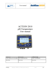
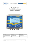
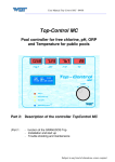
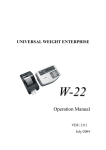
User manual
ACTEON 2020
Redox-Temperature
User manual
PONSEL
Ref.: NOTICE_ACTEON_2020_v003
V : 003
1/58
User manual
IMPORTANT
Read the manual carefully before switching the
device on.
In order to maintain and ensure the good working order of the device, users must comply with
the safety precautions and warnings featured in this manual.
Assembly and activation:
- Assembly, electrical connection, activation, operation and maintenance of the
measuring system must only be carried out by trained personnel duly authorised by the
end-user.
- Trained personnel must be familiar with and comply with the instructions in this
activation manual.
- Make sure the power supply complies with the specifications on the nameplate before
connecting the device.
- A clearly labelled power switch must be positioned near the device.
- Check all connections before turning the power on.
- Do not use damaged equipment: it may represent a hazard and should be labelled as
faulty.
- Repairs must only be carried out by the manufacturer or by a Ponsel after-sales
service.
PONSEL
Ref.: NOTICE_ACTEON_2020_v003
V : 003
2/58
User manual
CONTENTS
1
THE MEASURING SYSTEM................................................................................6
1.1
The basic system ..................................................................................................................................... 6
1.1.1
A Redox-Temperature transmitter ....................................................................................................... 6
1.1.2
A Redox sensor .................................................................................................................................... 6
1.1.3
A temperature sensor ........................................................................................................................... 6
1.2
Accessories............................................................................................................................................... 7
1.2.1
Consumables ........................................................................................................................................ 7
1.2.2
Sensor connector adapter ..................................................................................................................... 7
1.2.3
Accessories for a tank-mounted installation without cleaning system................................................. 7
1.2.4
Accessories for Redox filling sensors (PONCPC-PH-RV-10)........................................................... 7
1.2.5
Accessories for Redox (PONCPC-EH-10) and Temperature (PONCPC-T-10) sensor in-pipe
installation........................................................................................................................................................... 8
2
INSTALLATION ...................................................................................................9
2.1
Mounting the ACTEON 2020 transmitter box..................................................................................... 9
2.2
Connecting the ACTEON 2020 transmitter and pH and Temperature sensors ............................. 10
2.2.1
ACTEON 2020 wiring ....................................................................................................................... 12
2.3
Tank-mounting: .................................................................................................................................... 12
2.3.1
Using the stand and protective hood .................................................................................................. 12
2.3.2
Installing the sensor with a sensor-holder perch (elbowed or straight) and nozzle (PONPPCCPH/EH or PONPPCD-PH/EH)....................................................................................................................... 13
2.3.3
Installing an Elbowed Sensor-Holder Perch (ref: PONPPCC-CIR) or Straight Sensor-Holder Perch
(ref: PONPPCD-CIR) on QRPM (ref: PONSPFR and PONSPFR2) ............................................................ 15
2.4
In-pipe installation................................................................................................................................ 16
3
3.1
ACTEON 2020 TRANSMITTER.........................................................................17
Control console...................................................................................................................................... 17
4
BLOCK DIAGRAM OF ACTEON 2020 MENUS ................................................18
5
THE MEASUREMENT WINDOW.......................................................................19
6
CALIBRATING THE ACTEON 2020..................................................................20
6.1
Calibrating the sensors ......................................................................................................................... 20
6.1.1
Two point Redox (ORP) sensor calibration (complete calibration) ................................................... 21
6.1.2
Redox sensor slope adjustment .......................................................................................................... 24
6.1.3
Returning to REDOX measurement theoretical calibration ............................................................... 26
6.1.4
Two point temperature sensor calibration (complete calibration)...................................................... 27
6.1.5
Temperature sensor slope adjustment ................................................................................................ 30
6.1.6
Returning to temperature measurement theoretical calibration.......................................................... 32
6.2
Redox sensor calibration error message ............................................................................................. 33
6.2.1
Automatic zero measurement error .................................................................................................... 33
6.2.2
240mV or 470mV buffer solution calibration error ........................................................................... 33
6.3
Temperature sensor calibration error message information ............................................................ 33
6.3.1
0°C calibration error .......................................................................................................................... 33
6.3.2
Ambient water calibration error ......................................................................................................... 34
PONSEL
Ref.: NOTICE_ACTEON_2020_v003
V : 003
3/58
User manual
7
VIEWING MEASUREMENT HISTORY ..............................................................35
8
VIEWING THE SENSOR CALIBRATION REPORT ..........................................36
9
CONFIGURING ACTEON 2020 .........................................................................37
9.1
9.2
9.3
9.3.1
9.3.2
9.4
9.4.1
9.4.2
9.5
9.6
9.7
Configuring sensor response averaging .............................................................................................. 38
Configuring the trend line.................................................................................................................... 39
Configuring the two 4-20mA outputs.................................................................................................. 40
Adjusting 4-20mA output stop thresholds ......................................................................................... 41
Calibrating 4-20mA outputs............................................................................................................... 43
Adjusting relay outputs ........................................................................................................................ 45
Configuring relays in mode 1:............................................................................................................ 46
Configuring relays in mode 2:............................................................................................................ 47
Adjusting measurement units .............................................................................................................. 48
Setting the language.............................................................................................................................. 49
Resetting factory default values........................................................................................................... 50
10 INFORMATION MENU.......................................................................................51
11 ADJUSTING THE ACTEON 2020 DISPLAY CONTRAST ................................52
12 TECHNICAL SPECIFICATIONS:.......................................................................52
13 SENSORS ..........................................................................................................53
13.1
REDOX (ORP) sensor .......................................................................................................................... 53
13.1.1 Specifications:.................................................................................................................................... 53
13.1.2 Description:........................................................................................................................................ 53
13.1.3 Activation:.......................................................................................................................................... 53
13.1.4 Maintenance:...................................................................................................................................... 54
13.1.5 Cleaning: ............................................................................................................................................ 54
13.2
Temperature sensor.............................................................................................................................. 54
13.2.1 Maintenance:...................................................................................................................................... 54
13.2.2 Mechanical diagram........................................................................................................................... 55
14 QUESTIONS & ANSWERS................................................................................56
14.1
Display screen troubleshooting ............................................................................................................ 56
15 APPENDIX: ........................................................................................................57
PONSEL
Ref.: NOTICE_ACTEON_2020_v003
V : 003
4/58
User manual
Figures
Figure 1 - Transmitter mounting diagram ............................................................................................................... 9
Figure 2 - Installing a measuring system .............................................................................................................. 10
Figure 3 – Installation with a connection box with integrated pre-amplifier ........................................................ 11
Figure 4 - Mount and hood for the transmitter ...................................................................................................... 12
Figure 5 – PVC Elbowed Sensor-Holder Perch .................................................................................................... 13
Figure 6- Cross section diagram of the sensor nozzle without cleaning system ................................................... 14
Figure 7 – Installing a perch on a QRPM with one or two sliders ........................................................................ 15
Figure 8 - Installing a temperature sensor inside a pipe........................................................................................ 16
Figure 9 - Installing a temperature sensor in a pipe .............................................................................................. 16
Figure 10 - Redox sensor diagram ........................................................................................................................ 53
Figure 11 - Resetting ACTEON 2000................................................................................................................... 56
Figure 12 - Transmitter wiring terminal layout..................................................................................................... 57
PONSEL
Ref.: NOTICE_ACTEON_2020_v003
V : 003
5/58
User manual
1 The measuring system
1.1
The basic system
A measuring system requires the following basic elements:
1.1.1 A Redox-Temperature transmitter
PONACTEON2020-EH-T
ACTEON 2020 Redox meter and thermometer
transmitter
The Redox-Temperature transmitter comes with a 240mV buffer solution and a user manual.
1.1.2 A Redox sensor
Three sensors are available for different applications :
PONCPC-EH-10
PONCPC-EHAN-10
PONCPC-EH-RV-10
Plastogel electrolyte Eh sensor (platinum tip) with 10m
cable connection (perch mounting or in-pipe installation)
Plastogel electrolyte Eh sensor (platinum ring) with 10m
cable connection (perch mounting or in-pipe installation)
Glass bodied Eh filling sensor with 10-metre cable
connection
For cold liquids with very low conductivity (less than 50µS/cm) and contaminating media, it is recommended
to use a filling sensor.
1.1.3 A temperature sensor
Two sensors are available for different types of installation:
PONCPC-T-10
PONSEL
Temperature sensor with 10m cable connection (perchmounting or in-pipe installation)
Ref.: NOTICE_ACTEON_2020_v003
V : 003
6/58
User manual
1.2
Accessories
1.2.1 Consumables
PONMANU-2020-EH-T
PONKCL-1M
PONKCL-2M
PONKCL-3M
PONPEPNET
PONSOLCSV
PONEHSOL240
PONEHSOL470
PONFILP-EHAN
Additional ACTEON 2020 user manual
KCI (1M) for Eh filling sensors
KCI (2M) for Eh filling sensors
KCI (3M) for Eh filling sensors
125ml bottle of pepsin cleaning solution for Eh and pH sensors
125ml bottle of storage solution for pH/Eh sensors
Buffer solution for Redox meters: 240mV at 25°C, 125ml bottle
Buffer solution for Redox meters: 470mV at 25°C, 125ml bottle
ACTEON 2020 earth wire
1.2.2 Sensor connector adapter
These adapters are used to connect ACTEON 2020 units to PONSEL sensors with connectors.
PONADAP-EHAN
PONADAP-T
ACTEON 2020 adapter for PONCPC-EHAN-S10 and PONCPC-EH-S10
sensors
Adapter for PONCPC-T-S10 sensor
1.2.3 Accessories for a tank-mounted installation without cleaning system
PON-BJAI-E PH/EH/T
Watertight IP 68 connection box with integrated pre-amplifier (supplied
with 10 metres of cable) for pH/Eh and temperature sensors connections
at distances over 10 metres (see Figure 3 – Installation with a connection
box with integrated pre-amplifier
PONCBMC-9
PON-ACT-24V
PON-PDPCV-1
PON-PDPCV-2
PON-CASQ-1
PON-CASQ-2
PONPPCC-PH/EH/T
9-conductor coated cable for the Connection box/Acteon connection
Optional 24VDC power supply
PVC stand and protective hood for one ACTEON transmitter
PVC stand and protective hood for two ACTEON transmitters
PVC protective hood for one ACTEON transmitter
PVC protective hood for two ACTEON transmitters
Elbowed sensor-holder perch (ESHP) for pH/Eh or Temperature sensors.
Supplied with nozzle and glued connector.
Straight sensor-holder perch for pH/Eh and Temperature sensors supplied
with nozzle and glued connector SPECIFIC APPLICATION
Nozzle for pH/Eh (without cleaning system) and Temperature sensors.
Complete with 50 diameter BP3P glued connector
90° elbow for sensor-holder perch closure
Stainless steel ESHP or SSHP type mount for 2 perches -1 arm, 2 sliders
Stainless steel ESHP or SSHP type mount for 1 perch -1 arm, 1 slider
Additional slider for QRPM (Quick release perch mount) systems
PONPPCD-PH/EH/T
PONBUSE-PH/EH/T
PONCOUDE
PONSPFR2C
PONSPFR1C
PONSPFR-COUL
1.2.4 Accessories for Redox filling sensors (PONCPC-PH-RV-10)
PONRAC-EH-RV
PONRES-EH-RV
PONROB-EH-RV
PONROB-EH-RV
PONSEL
Connector for filling system
5-litre capacity electrolyte tank for filling system
Electrolyte tank tap for filling systems
10-metre tube for connecting the tank to the strainer and for filling
systems
Ref.: NOTICE_ACTEON_2020_v003
V : 003
7/58
User manual
PONCREP-EH-RV
Filling system strainer
1.2.5 Accessories for Redox (PONCPC-EH-10) and Temperature (PONCPC-T-10) sensor
in-pipe installation
PON4020
PON40
PONAP1
PONVCPO-63
PONNIP-PH/EH
PONNIP-PH/EH-T
PONNIP-T
PONSEL
Tee assembly fitted with 20 x 27 male/female sockets for AP1. To be
fitted on PVC piping.
40 diameter glued tee assembly (without connectors) for AP1
Adapter sleeve for pH and temperature sensor in-pipe installation
Stainless steel 63mm clamp type assembly for in-pipe installation (316 L)
(for SS OXY, Eh, pH, Temp., C2E and C4E sensors) To be fitted with the
appropriate nipple. To be fitted on stainless steel piping.
pH/Eh sensor nipple
Nipple for 2 pH/T or Eh/T or pH/Eh sensors
Temperature sensor nipple
Ref.: NOTICE_ACTEON_2020_v003
V : 003
8/58
User manual
2 Installation
2.1
Mounting the ACTEON 2020 transmitter box
ACTEON 2020 mounting diagram
Dimensions (mm)
PONSEL
A
B
C
156.5
181
195.3
Figure 1 - Transmitter mounting diagram
Ref.: NOTICE_ACTEON_2020_v003
V : 003
9/58
User manual
2.2
Connecting the ACTEON 2020 transmitter and pH and Temperature sensors
•
Case 1 : the distance between the sensors and the transmitter is less than 10 meters
1
Power supply cable (230V/110 V~
or 24VDC)
2
Line out cable
3
Relay cable (2 channels)
4
4-20mA cable (2 channels)
5
Redox (ORP) sensor
(PONCPC-EHAN-10)
6
Temperature sensor
(PONCPC-T-10)
1
2
4
3
5
6
Figure 2 - Installing a measuring system
PONSEL
Ref.: NOTICE_ACTEON_2020_v003
V : 003
10/58
User manual
•
Case 2 : the distance between the transmitter and the sensors is longer than 10 metres:
A watertight IP 68 connection box with integrated pre-amplifier must be used (REF: PON-BJAI-E PH/EH/°C).
1
2
3
1
Power supply cable (230/110V~
or 24VDC)
2
Line out cable
3
Relay cable (2 channels)
4
4-20mA cable (2
channels)
5
Redox (ORP) sensor
(PONCPC-EHAN-10)
6
Temperature sensor
(PONCPC-T-10)
7
Connection box
(PON-BJAI-E
PH/EH/T)
4
7
5
6
Figure 3 – Installation with a connection box with integrated pre-amplifier
PONSEL
Ref.: NOTICE_ACTEON_2020_v003
V : 003
11/58
User manual
2.2.1 ACTEON 2020 wiring
See appendix (§15) at the end of the document.
2.3
Tank-mounting:
2.3.1 Using the stand and protective hood
A protective hood (PON-PDPVC-1) is available for mounting the ACTEON 2020.
The hood is essential in the case of direct exposure to adverse weather or sunshine.
Figure 4 - Mount and hood for the transmitter
PONSEL
Ref.: NOTICE_ACTEON_2020_v003
V : 003
12/58
User manual
2.3.2 Installing the sensor with a sensor-holder perch (elbowed or straight) and
nozzle (PONPPCC-PH/EH or PONPPCD-PH/EH)
2.20m
It is best to use the elbowed sensor-holder perch when immersing the sensor in a tank.
Sensor-holder perch
Glued connector
Sensor-holder nozzle
Lock- nut
45°
Liquid level
55cm
Flow direction of liquid
50cm
minimum
Sensor in the nozzle
Figure 5 – PVC Elbowed Sensor-Holder Perch
Comment:
Use elbowed sensor-holder perches in heavily soiled tanks to prevent fibre build-up on the perch.
Installing the pH sensor in the nozzle:
1) Dismantle the sensor-holder perch then remove the nozzle from the bottom of the perch by removing its
tightening screw.
2) Introduce a solid wire into the perch then a string.
3) Remove the sensor's protective casing and two O-ring seals.
Henceforth, handle the sensor with care. The warranty does not cover breakage of the glass bulb.
PONSEL
Ref.: NOTICE_ACTEON_2020_v003
V : 003
13/58
User manual
4) Attach the string to the end of the sensor and introduce it into the top of the perch. Use the string to pull
the sensor to the bottom of the perch.
5) Remove the string and place the sensor in the nozzle. The sensor should protrude about twenty
centimetres.
6) Replace only the O-ring seal nearest the glass section of the sensor.
7) Adjust the tip of the sensor exactly flush with the end of the nozzle. Secure the sensor in place with the
tightening screw.
8) Replace the nozzle on the perch and secure it with the tightening screw.
9) Use the stand with a slider or another sort of system to set the perch in a vertical position. Adjust the
immersion parameters so that the nozzle always remains submerged and the submerged section is
always at least 0.50m below the surface.
10) To prevent fibre build-up, position the sensor so that the nozzle is facing in the same direction as the
flow.
Diagram of the sensor in the nozzle without cleaning system
Water earth cable
Nozzle (PONBUSE-PH/EH/T)
EH SENSOR (PONCPC-EHAN-10)
Figure 6- Cross section diagram of the sensor nozzle without cleaning system
Comment: The line out cable is to be connected to the ACTEON 2000 earth terminal.
PONSEL
Ref.: NOTICE_ACTEON_2020_v003
V : 003
14/58
User manual
2.3.3 Installing an Elbowed Sensor-Holder Perch (ref: PONPPCC-CIR) or Straight
Sensor-Holder Perch (ref: PONPPCD-CIR) on QRPM (ref: PONSPFR and
PONSPFR2)
1) Fix the stainless steel QRPM to the infrastructure.
2) Next, fix a sensor-holder perch to the stainless steel QRPM as shown in the diagram below.
Figure 7 – Installing a perch on a QRPM with one or two sliders
A second slider may be added to install a second sensor-holder perch for the temperature sensor (see diagram
above).
PONSEL
Ref.: NOTICE_ACTEON_2020_v003
V : 003
15/58
User manual
2.4
In-pipe installation
For in-pipe installations, use the tee assembly (PON-4020) and the adapter sleeve (PONAP1).
Redox sensor (PONCPC-EH-10
or PONCPC-EHAN-10)
Sleeve (PONAP1)
Tee (PON4020)
20x27 connectors
Figure 8 - Installing a temperature sensor inside a pipe
Temperature sensor (PONCPC-T-10)
Sleeve (PONAP1)
Tee (PON4020)
20x27 connectors
Figure 9 - Installing a temperature sensor in a pipe
PONSEL
Ref.: NOTICE_ACTEON_2020_v003
V : 003
16/58
User manual
3 ACTEON 2020 transmitter
3.1
Control console
7
3
5
1
4
2
6
8
1
ENTER key for accessing menus or confirming actions
2
ESC key for exiting menus or cancelling actions
3
for moving left in menus
4
for moving right in menus
5
for increasing a value or selecting the menu above
6
for decreasing a value or selecting the menu below
7
Control screen
8
Quarter-turn screw to seal cover
PONSEL
Ref.: NOTICE_ACTEON_2020_v003
V : 003
17/58
User manual
4 Block diagram of ACTEON 2020 menus
Redox sensor
HISTORY
Gain adjust (§6.1.2)
Complete calibration (§6.1.1)
CALIBRATION
Theoretical calibration (§6.1.3)
CALIBRATION
LOGGER
Temperature sensor
Gain adjust (§6.1.5)
Complete calibration (§6.1.4)
Theoretical calibration (§ 6.1.6)
Adjusting the graphic screen (§9.2)
CONFIGURATION
4-20mA output
adjustment
MEASURE
Config. of 4mA and 20mA
stop switches (§9.3.1)
4-20mA output calibration
(§9.3.2)
Threshold adjustment in
mode 1 (§0)
Relay adjustment
Threshold adjustment in
mode 2 (§9.4.2)
Measure unit configuration (§9.5)
Language configuration (§9.6)
GENERAL
INFORMATION
PONSEL
Ref.: NOTICE_ACTEON_2020_v003
Factory default configuration reminder (§9.7)
V : 003
18/58
User manual
5 The measurement window
In measure mode the measurement screen displays various information:
6
ACTEON 2020 ORP
MEASURE
281
300
!
100
-24h
LOG
HIST CAL
1
Redox measurement
2
Measurement state indicator:
!
!
3
4
INFO
5
THEOR CAL
: Use of the theoretical coefficients as calibration coefficients.
CAL
: Incorrect calibration point on the probe.
No icon displayed
3
Mode1 R1
R2
CONF
1
2
CAL
20.00 °C
mV
MEAS
mV
: The last calibration is correct.
Temperature transmitted by the temperature sensor
In the event of faulty wiring or uninstalled sensor, the temperature will not be displayed.
Comment: The following icon is displayed if the temperature is higher than the operating
temperature (55°C)
!
HOT
4
R1 and R2 relays: state and operating mode
Contact is inactive.
Contact is active.
5
ACTEON menu
6
Trend line can be configured from 1 min to 24 hours (with automatic scaling)
PONSEL
Ref.: NOTICE_ACTEON_2020_v003
V : 003
19/58
User manual
6 Calibrating the ACTEON 2020
6.1
Calibrating the sensors
Select the calibration menu in the measurement window:
ACTEON 2020 ORP
MEASURE
290 mV
300
20.00 °C
mV
200 Mode1
-24 hrs
MEAS
HIST
CAL
LOG
CONF
INFO
Select the
CALIBRATION
R1
R2
CAL
Use the and keys to
navigate the ACTEON menu
menu then press ENTER
SENSORS CALIBRATION
ORP SENSOR
Gain adjust
Complete calibration
Theoretical calibration
TEMPERATURE SENSOR
Gain adjust
Complete calibration
Theoretical calibration
ENTER: Validate the choice
PONSEL
Ref.: NOTICE_ACTEON_2020_v003
V : 003
20/58
User manual
6.1.1
Two point Redox (ORP) sensor calibration (complete calibration)
Use the following procedure to calibrate your Redox sensor.
You will need the 240mV or 470mV Redox buffer solution for this procedure.
CALIBRATION
SENSORS CALIBRATION
ORP SENSOR
Gain adjust
Complete calibration
Theoretical calibration
TEMPERATURE SENSOR
Gain adjust
Complete calibration
Theoretical calibration
Use the and keys to
select the type of calibration
and the probe to be calibrated.
ENTER: Validate the choice
Select the ENTER.
CALIBRATION
Complete calibration
menu and press
ORP SENSOR
Enter your name:
Durant
ESC: Cancel the procedure
ENTER: Start calibration
Use the and keys to move the
cursor in the name section.
Use the and keys to change the
letters. (The scrolling order of the
letters is A…Z,0..9,?,>,space )
Enter your name or reference then press ENTER
PONSEL
Ref.: NOTICE_ACTEON_2020_v003
V : 003
21/58
User manual
ORP SENSOR
CALIBRATION
Automatic zero
0
0
Standard:
Measure:
mV
mV
ESC: Cancel the procedure
ENTER: Validate the pH7
No
Calibration
Correct
If the automatic zero is incorrect, an error message
window appears (see "Error message information"
chapter §6.2.1)
Yes
Immerse the Redox sensor in the 240mV or 470mV
ORP standard solution
CALIBRATION
ORP SENSOR
Immerse the sensor in
an ORP standard solution
Standard:
Measure:
240
234
mV
mV
WAIT: Nonstable measurement
Use the and keys to adjust
the buffer value (from 0mV to
999mV)
ESC: Leave the current slope
ENTER: Validate the new slope
AWAIT MEASUREMENT STABILISATION
Press the ENTER key to confirm the second
calibration point
PONSEL
Ref.: NOTICE_ACTEON_2020_v003
V : 003
22/58
User manual
.
No
Calibration
Correct
If the second calibration point is incorrect, an error
message window appears (see "Error message
information" chapter §6.2.2)
Yes
ACTEON 2020 ORP
MEASURE
290 mV
300
20.00 °C
mV
200 Mode1
-24 hrs
MEAS
PONSEL
HIST
CAL
LOG
CONF
R1
R2
Comment: The
measurement window is
displayed again once the
calibration has been
correctly carried out.
INFO
Ref.: NOTICE_ACTEON_2020_v003
V : 003
23/58
User manual
6.1.2 Redox sensor slope adjustment
You can only adjust the slope of your sensor by carrying out the following procedure :
CALIBRATION
SENSOR CALIBRATION
ORP SENSOR
Gain adjust
Complete calibration
Theoretical calibration
TEMPERATURE SENSOR
Gain adjust
Complete calibration
Theoretical calibration
Use the andkeys to select
the type of calibration and the
probe to be calibrated.
ENTER: Validate the choice
Select the ENTER.
Gain adjust
menu and press
Immerse the Redox sensor in the 240mV or 470mV
ORP standard solution.
CALIBRATIO
N
ORP SENSOR
Immerse the sensor in
an ORP standard solution
Standard:
Measure:
240
234
mV
mV
WAIT: Nonstable measurement
ESC: Leave the current slope
ENTER: Validate the new slope
Use the and keys to
adjust the buffer value (0mV to
999mV)
AWAIT MEASUREMENT STABILISATION
Press the ENTER key to confirm gain adjust.
PONSEL
Ref.: NOTICE_ACTEON_2020_v003
V : 003
24/58
User manual
No
Calibration
Correct
If the second calibration point is incorrect, an error
message window appears (see "Error message
information" chapter §6.2.2)
Yes
ACTEON 2020 ORP
MEASURE
290 mV
300
20.00 °C
mV
200 Mode1
-24 hrs
MEAS
PONSEL
HIST
CAL
LOG
CONF
R1
R2
Comment: The
measurement window is
displayed again once gain
adjust has been correctly
carried out.
INFO
Ref.: NOTICE_ACTEON_2020_v003
V : 003
25/58
User manual
6.1.3 Returning to REDOX measurement theoretical calibration
Theoretical calibration is carried out using the theoretical coefficients.
Follow the instructions below to carry out theoretical calibration:
SENSORS CALIBRATION
CALIBRATION
ORP SENSOR
Gain adjust
Complete calibration
Theoretical calibration
TEMPERATURE SENSOR
Gain adjust
Complete calibration
Theoretical calibration
Use the andkeys to select
the type of calibration and the
probe to be calibrated.
ENTER: Validate the choice
Select the Theoretical
press ENTER.
calibration
menu and
THEORETICAL CALIBRATION
CALIBRATION
ATTENTION, you will erase your
calibration coefficients to return to
the theoretical coefficients!
Yes
No
Esc: Cancel the procedure
Enter: Validate the choice
Use the andkeys to select the
procedure confirmation.
Select Yes and press ENTER to return to the
theoretical coefficients.
ACTEON 2020 ORP
MEASUR
E
290 mV
! THEOR CAL
Indicates that the device has
been calibrated with the
theoretical coefficients.
300
20.00 °C
mV
200 Mode1
-24 hrs
MEAS
PONSEL
HIST
CAL
LOG
CONF
R1
R2
INFO
Ref.: NOTICE_ACTEON_2020_v003
V : 003
26/58
User manual
6.1.4 Two point temperature sensor calibration (complete calibration)
Use the following procedure to completely calibrate your temperature sensor.
You will need a precision thermometer and water at 0°C for this procedure.
CALIBRATION
SENSORS CALIBRATION
ORP SENSOR
Gain adjust
Complete calibration
Theoretical calibration
TEMPERATURE SENSOR
Gain adjust
Complete calibration
Theoretical calibration
ENTER: Validate the choice
Use the andkeys to select
the type of calibration and the
probe to be calibrated.
Select the Complete calibration menu of the
temperature sensor and press ENTER.
CALIBRATION
TEMPERATURE SENSOR
Enter your name:
Durant
ESC: Cancel the procedure
ENTER: Start calibration
Use the and keys to move the
cursor in the name section.
Use the and keys to change the
letters. (The scrolling order of the
letters is A…Z,0..9,?,>,space)
Enter your name and reference and press ENTER.
Immerse the sensor in a water and crushed ice
mixture at 0.00°C.
PONSEL
Ref.: NOTICE_ACTEON_2020_v003
V : 003
27/58
User manual
CALIBRATIO
N
TEMPERATURE SENSOR
Immerse the sensor in
water and ice
Standard:
Measure:
°C
°C
0.00
0.15
WAIT: Nonstable measurement
Use the and keys to adjust the
water temperature value.
ESC: Cancel the procedure
ENTER: Validate the zero
AWAIT MEASUREMENT STABILISATION
Press the ENTER key to confirm the first
calibration point.
No
Calibration
Correct
If the first calibration point is incorrect, an error
message window appears (see "Error message
information" chapter §6.3.1)
Yes
Immerse the sensor in water at ambient temperature.
CALIBRATION
TEMPERATURE SENSOR
Immerse the sensor in
water at ambient temperature
Standard:
Measure:
20.00
20.20
°C
°C
WAIT: Nonstable measurement
ESC: Leave the current slope
ENTER: Validate the new slope
Use the and keys to adjust the
water temperature value.
AWAIT MEASUREMENT STABILISATION
Press the ENTER key to confirm the second
calibration point.
PONSEL
Ref.: NOTICE_ACTEON_2020_v003
V : 003
28/58
User manual
No
Calibration
Correct
If the second calibration point is incorrect, an error
message window appears (see "Error message
information" chapter §6.2.2)
Yes
ACTEON 2020 Redox
MEASURE
290 mV
300
20.00 °C
mV
200 Mode1
-24 hrs
MEAS
PONSEL
HIST
CAL
LOG
CONF
R1
R2
INFO
Ref.: NOTICE_ACTEON_2020_v003
Comment: The
measurement window is
displayed again once the
calibration has been
correctly carried out.
V : 003
29/58
User manual
6.1.5 Temperature sensor slope adjustment
If you observe a small measurement error, you may only adjust the slope of your sensor by carrying out the
following procedure:
CALIBRATION
SENSORS CALIBRATION
OPR SENSOR
Gain adjust
Complete calibration
Theoretical calibration
TEMPERATURE SENSOR
Gain adjust
Complete calibration
Theoretical calibration
Use the andkeys to select
the type of calibration and the
probe to be calibrated.
ENTER: Validate the choice
Select the Gain adjust
menu and press ENTER.
Immerse the sensor in water at ambient temperature.
CALIBRATION
TEMPERATURE SENSOR
Immerse the sensor in
water at ambient temperature
Standard:
Measure:
20.00
20.20
°C
°C
:
WAIT: Nonstable measurement
ESC: Leave the current slope
ENTER: Validate the new slope
Use the and keys to adjust the
ambient water temperature value.
AWAIT MEASUREMENT STABILISATION
Press the ENTER key to confirm slope
adjustment.
PONSEL
Ref.: NOTICE_ACTEON_2020_v003
V : 003
30/58
User manual
No
Calibration
Correct
If the second calibration point is incorrect, an error
message window appears (see "Error message
information" chapter §6.3.2)
Yes
ACTEON 2020 ORP
MEASURE
290 mV
300
20.00 °C
mV
200 Mode1
-24 hrs
MEAS
PONSEL
HIST
CAL
LOG
CONF
R1
R2
Comment: The
measurement window is
displayed again once gain
adjust has been correctly
carried out.
INFO
Ref.: NOTICE_ACTEON_2020_v003
V : 003
31/58
User manual
6.1.6 Returning to temperature measurement theoretical calibration
Theoretical calibration is carried out using the theoretical coefficients (PT100 theoretical slope and offset
zeroing).
Follow the instructions below to carry out theoretical calibration
SENSORS CALIBRATION
CALIBRATIO
N
ORP SENSOR
Gain adjust
Complete calibration
Theoretical calibration
TEMPERATURE SENSOR
Gain adjust
Complete calibration
Theoretical calibration
Use the andkeys to select
the type of calibration and the
probe to be calibrated.
ENTER: Validate the choice
Select the Theoretical
press ENTER.
calibration
menu and
THEORETICAL CALIBRATION
CALIBRATION
ATTENTION, you will erase your calibration
coefficients to return to the theoretical
coefficients!
Yes
No
Esc: Cancel the procedure
Enter: Validate the choice
Use the andkeys to select the
procedure confirmation.
Select Yes and press ENTER to return to the
theoretical coefficients.
ACTEON 2020 ORP
MEASURE
290 mV
300
20.00 °C
mV
200 Mode1
-24 hrs
MEAS
PONSEL
HIST
CAL
LOG
CONF
R1
R2
INFO
Ref.: NOTICE_ACTEON_2020_v003
V : 003
32/58
User manual
6.2
Redox sensor calibration error message
6.2.1 Automatic zero measurement error
CALIBRATION
ORP SENSOR
CALIBRATION IMPOSSIBLE
Offset:
NON CORRECT
Esc: Escape menu
If you observe an error during automatic zero measurement: Contact the after-sales service (see last page)
6.2.2 240mV or 470mV buffer solution calibration error
CALIBRATION
ORP SENSOR
CALIBRTION IMPOSSIBLE
Slope:
NON CORRECT
Esc: Escape menu
If an error occurs during calibration with the 240mV or 470mV buffer:
1) Check if the buffer is fouled or out-of-date.
2) Check the connection between the sensor and ACTEON 2020.
3) Clean the platinum electrode (the sensor's response will be weak if the platinum electrode is soiled).
6.3
Temperature sensor calibration error message information
6.3.1 0°C calibration error
CALIBRATION
TEMPERATURE SENSOR
CALIBRATION IMPOSSIBLE
Offset:
NON CORRECT
Esc: Escape menu
PONSEL
Ref.: NOTICE_ACTEON_2020_v003
V : 003
33/58
User manual
If an error occurs during calibration in water at 0°C:
1) Check the water temperature with a precision thermometer.
2) Check the connection between the temperature sensor and ACTEON 2020.
6.3.2 Ambient water calibration error
CALIBRATION
TEMPERATURE SENSOR
CALIBRATION IMPOSSIBLE
Slope:
NON CORRECT
Esc: Escape menu
If an error occurs during calibration in water at ambient temperature:
1) Check the water temperature with a precision thermometer.
2) Check the connection between the temperature sensor and ACTEON 2020.
PONSEL
Ref.: NOTICE_ACTEON_2020_v003
V : 003
34/58
User manual
7 VIEWING MEASUREMENT HISTORY
The history menu can be used to consult the last 100 data items recorded and displayed on the trend line.
To view this data, follow the instructions below :
ACTEON 2020 ORP
MEASURE
290 mV
300
20.00 °C
mV
200 Mode1
-24 hrs
MEAS
HIST
CAL
LOG
CONF
Use the and keys to
navigate the ACTEON menu.
INFO
Select the
HISTORY
R1
R2
HIST
menu and press ENTER.
453 mV
500
20.00 °C
mV
- 4 hrs
300
-24 hrs
ESC: Escape menu
PONSEL
Ref.: NOTICE_ACTEON_2020_v003
Use the and keys to move the
cursor along the trend line.
V : 003
35/58
User manual
8 VIEWING THE SENSOR CALIBRATION REPORT
The calibration logger is used to check the reports of the most recent calibrations.
Follow the instructions below to access this information:
ACTEON 2020 ORP
MEASURE
290 mV
300
20.00 °C
mV
200 Mode1
-24 hrs
MEAS
HIST
CAL
CONF
LOG
INFO
Select the
CALIB LOG
R1
R2
LOG
Use the and keys to
navigate the ACTEON menu.
menu and press ENTER.
CALIBRATION LOGGER
Calibration of
redox sensor
CORRECT
Standard 1: 0mV
Standard 2: 240mV
Offset:
1mV
Slope:
110%
Name: Ponsel
Calibration of
Temperature sensor
CORRECT
Standard 1: 0.01°C
Standard 2: 20.00°C
Offset:
1.65°C
Slope:
110%
Name: Ponsel
Esc: Escape menu
Message
CORRECT
THEORETICAL coef.
THEORETICAL slope
THEORETICAL offset
INCORRECT slope
INCORRECT offset
PONSEL
List of diagnostic messages from the last calibration :
Explanation
ACTEON 2020 has been calibrated correctly.
ACTEON 2020 is using the theoretical coefficients (slope and offset); this
message is displayed after a theoretical calibration.
ACTEON 2020 is using the theoretical slope.
ACTEON 2020 is using the theoretical offset.
ACTEON 2020 is incorrectly calibrated because the slope calculated during
calibration is incorrect (in this case ACTEON 2000 is using the last correctly
calculated slope).
ACTEON 2020 is incorrectly calibrated because the offset calculated during
calibration is incorrect (in this case ACTEON 2020 is using the last correctly
calculated offset).
Ref.: NOTICE_ACTEON_2020_v003
V : 003
36/58
User manual
9 CONFIGURING ACTEON 2020
Select the configuration menu in the measurement window:
ACTEON 2020 ORP
MEASURE
290 mV
300
20.00 °C
mV
200 Mode1
-24 hrs
MEAS
HIST
CAL
LOG
CONF
INFO
Select the
CALIBRATION
R1
R2
CONF
Use the and keys to
navigate the ACTEON menu.
menu and press ENTER.
WHAT DO YOU WANT TO DO?
Averaging sensor response
Graphic screen
4-20mA outputs adjustment
Relay adjustment
Measure units
Language
Factory default value reminder
ESC: Escape menu
PONSEL
Ref.: NOTICE_ACTEON_2020_v003
V : 003
37/58
User manual
9.1
Configuring sensor response averaging
This configuration makes the sensor response more stable and responsive.
By default, the averaging procedure involves 10 measurements. This means that the displayed value is the
average measurement over the last 10 seconds:
CONFIG
WHAT DO YOU WANT TO DO?
Averaging sensor response
Graphic screen
4-20mA outputs adjustment
Relay adjustment
Measure units
Language
Factory default value reminder
Select the ENTER.
CONFIG
Average on: 10
Use the andkeys to select
the configuration required.
Averaging sensor response
menu and press
AVERAGING SENSOR RESPONSE
measures.
1
= Instantaneous answer
100 = Answer very strongly averaged
Esc: Cancel the procedure
Enter: Validate the averaging
Use the and keys to increase
and decrease the averaging.
Select the averaging desired and press ENTER.
CONFIG
WHAT DO YOU WANT TO DO?
Averaging sensor response
Graphic screen
4-20mA outputs adjustment
Relay adjustment
Measure units
Language
Factory default value reminder
Comment:
Increase the averaging if your measurement is unstable.
PONSEL
Ref.: NOTICE_ACTEON_2020_v003
V : 003
38/58
User manual
Decrease the averaging if the measurement process is too slow.
9.2
Configuring the trend line
The trend line can be used to check regulation cycles and detect anomalies.
Follow the instructions below to adapt the time base to the trend line:
CONFIG
WHAT DO YOU WANT TO DO?
Averaging sensor response
Graphic screen
4-20mA outputs adjustment
Relay adjustment
Measure units
Language
Factory default value reminder
Select the ENTER
CONFIG
Use the andkeys to select
the configuration required.
Graphic screen
menu and press
GRAPHIC SCREEN
Configuration of the trend line
7 minutes
Time base:
Showing maximum range: 11 hours
Esc: Cancel the procedure
Enter: Validate the choice
Use the and keys to increase
the time base in order to adjust the
duration of the trend curve. (1 sec to
15 min).
Select the time base chosen and press ENTER.
CONFIG
WHAT DO YOU WANT TO DO?
Averaging sensor response
Graphic screen
4-20mA outputs adjustment
Relay adjustment
Measure units
Language
Factory default value reminder
PONSEL
Ref.: NOTICE_ACTEON_2020_v003
V : 003
39/58
User manual
9.3
Configuring the two 4-20mA outputs
Comment:
For greater 4-20mA output precision, it is advised to calibrate the outputs during activation.
CONFIG
WHAT DO YOU WANT TO DO?
Averaging sensor response
Graphic screen
4-20mA outputs adjustment
Relay adjustment
Measure units
Language
Factory default value reminder
Select the ENTER.
CONFIG
Use the andkeys to select
the configuration required.
4-20mA output adjustment
menu and press
4-20mA OUTPUTS
4-20mA output adjustment
4-20mA output calibration
PONSEL
Ref.: NOTICE_ACTEON_2020_v003
V : 003
40/58
User manual
9.3.1 Adjusting 4-20mA output stop thresholds
CONFIG
4-20mA OUTPUTS
4-20mA output adjustment
4-20mA output calibration
Use the andkeys to select
the configuration required.
Select the 4-20mA output adjustment menu and press
ENTER.
CONFIG
4-20mA OUTPUTS
NUMBER 1 FOR ORP
4mA adjustment:
2.00mV
20mA adjustment:
12.00mV
Esc: Escape menu
Enter: Validate the choice
Use the and keys to increase and
decrease the 4 and 20mA stop values.
Use the and keys to select 4mA or
20mA.
Configure the ORP 4-20mA output and press ENTER.
CONFIG
4-20mA OUTPUTS
No 2 FOR TEMPERATURE
4mA adjustment:
-5.00°C
20mA adjustment:
35.00°C
Esc: Escape menu
Enter: Validate the choice
PONSEL
Ref.: NOTICE_ACTEON_2020_v003
Use the and keys to increase
and decrease the 4 and 20mA stop
values.
Use the and keys to select
4mA or 20mA.
V : 003
41/58
User manual
Configure the 4-20mA output for temperature and
press ENTER.
CONFIG
WHAT DO YOU WANT TO DO?
Averaging sensor response
Graphic screen
4-20mA outputs adjustment
Relay adjustment
Measure units
Language
Factory default value reminder
PONSEL
Ref.: NOTICE_ACTEON_2020_v003
Comment: Both 4-20mA
outputs have been
configured correctly.
V : 003
42/58
User manual
9.3.2 Calibrating 4-20mA outputs
Calibrating the 4-20mA outputs improves their level of accuracy by taking into account the device load.
CONFIG
4-20mA OUTPUTS
4-20mA output adjustment
4-20mA output calibration
Use the andkeys to select
the configuration required.
Select the 4-20mA output calibration menu and
press ENTER.
CONFIG
Procedure:
Insert an ammeter on 4-20mA
outputs.
AMMETER
LOAD
ENTER: To continue
ESC: Escape menu
Connect an ammeter to the 4-20mA outputs and press
ENTER.
CONFIG
4-20mA OUTPUTS
CURRENT GENERATION OF 4mA
Enter the value
read on the ORP
4-20mA output
4.00mA
Enter the value read
on the temperature
4-20mA output
4.00mA
ESC: Escape menu
ENTER: To continue
PONSEL
Ref.: NOTICE_ACTEON_2020_v003
Use the and keys to increase
and decrease the4mA value.
Use the and keys to select the
ORP 4-20mA output or the
temperature 4-20mA output.
V : 003
43/58
User manual
Adjust the 4mA outputs and press ENTER.
CONFIG
4-20mA OUTPUTS
CURRENT GENERATION OF 20mA
Enter the value
read on the ORP
4-20mA output
20.00mA
Enter the value read
on the temperature
4-20mA output
20.00mA
Use the and keys to increase
and decrease the 20mA value.
Use the and keys to select the
ORP 4-20mA output or the
temperature 4-20mA output.
Adjust the 20mA outputs and press ENTER.
CONFIG
WHAT DO YOU WANT TO DO?
Averaging sensor response
Graphic screen
4-20mA outputs adjustment
Relay adjustment
Measure units
Language
Factory default value reminder
PONSEL
Ref.: NOTICE_ACTEON_2020_v003
V : 003
44/58
User manual
9.4
Adjusting relay outputs
The 2 relays can be configured in 2 different modes:
- Mode 1 is used to configure relay R1 on a Redox measurement value and relay R2 on a temperature
measurement value.
- Mode 2 is used to configure relays R1 and R2 on two Redox measurement values.
The 2 relays can be configured with the following attributes:
- Alarm threshold: Threshold trigger value
- Hysteresis: Hysteresis value for relay switching (prevents relay hunting)
- Triggering direction:
Above: Means the relay contact is closed above the alarm threshold.
Below: Means the relay contact is open below the alarm threshold.
- $$$mode 1: réglage en
alarme
CONFIG
WHAT DO YOU WANT TO DO?
Averaging sensor response
Graphic screen
4-20mA outputs adjustment
Relay adjustment
Measure units
Language
Factory default value reminder
Use the andkeys to select
the configuration required.
Esc: Escape menu
Select the CONFIG
Relay adjustment
menu and press ENTER.
Configuration of the relays
mode:
- Mode 1: Alarms adjustment
- Mode 2: Regulation 2 relays
Esc: Escape menu
Enter: Validate the choice
PONSEL
Ref.: NOTICE_ACTEON_2020_v003
Use the andkeys to select the
configuration required.
V : 003
45/58
User manual
9.4.1 Configuring relays in mode 1:
MODE 1: ADJUSTMENT OF THE
THRESHOLDS AND HYSTERESIS
CONFIG
Rel 1 connected to redox measurement:
Alarm threshold: 50mV Hyst: 10mV
Below the threshold, R1 is on
Rel 2 connected to temperature measurement:
Alarm threshold: 20.01°C Hyst: 0.06°C
Above the threshold, R2 is on
Esc: Cancel the procedure
Enter: Validate the choice
Use the andkeys to
increase the values.
Use the and keys to
navigate the selections.
Configure the two relays and press ENTER.
WHAT DO YOU WANT TO DO?
CONFIG
Graphic screen
4-20mA outputs adjustment
Relay adjustment
Measure units
Language
Factory default value reminder
In the above example, the relays are configured as indicated below:
Redox
Alarm
threshold
e
50
40
Hysteresis
Inactive
Active
Inactive
Active
R1
Temperature
Alarm
threshold
20.01
19.95
Hysteresis
Active
Inactive
R2
PONSEL
Ref.: NOTICE_ACTEON_2020_v003
Inactive
Active
V : 003
46/58
User manual
9.4.2 Configuring relays in mode 2:
MODE 2: ADJUSTMENT OF THE
THRESHOLDS AND HYSTERESI
CONFIG
Rel 1 connected to redox measurement:
Alarm threshold: -150mV Hyst: 10mV
Below the threshold, R1 is on
Rel 2 connected to redox measurement:
Alarm threshold: 50mV Hyst: 10mV
Above the threshold, R2 is on
Use the and keys to
increase the values.
Use the and keys to
navigate the selections.
Esc: Cancel the procedure
Enter: Validate the choice
Configure the two relays and press ENTER.
WHAT DO YOU WANT TO DO?
CONFIG
Averaging sensor response
Graphic screen
4-20mA outputs adjustment
Relay adjustment
Measure units
Language
Factory default value reminder
In the above example, the relays are configured as indicated below:
Alarm
threshold
R2
Alarm
threshold
R1
50
40
Hysteresis
-140
-150
Hysteresis
Inactive
Active
Inactive
Active
R1
R2
PONSEL
Active
Inactive
Ref.: NOTICE_ACTEON_2020_v003
Active
Inactive
V : 003
47/58
User manual
9.5
Adjusting measurement units
ACTEON 2020 can be configured in °C and °F for temperature measurement.
CONFIG
WHAT DO YOU WANT TO DO?
Averaging sensor response
Graphic screen
4-20mA outputs adjustment
Relay adjustment
Measure units
Language
Factory default value reminder
Select the CONFIG
Use the andkeys to select
the configuration required.
Measure units
menu and press ENTER.
UNITES
Temperature:
°C: degree Celsius
°F: degree Fahrenheit
Esc: Cancel the procedure
Enter: Validate the choice
Use the andkeys to select the
unit desired.
Select the required measurement unit and press ENTER.
CONFIG
PONSEL
WHAT DO YOU WANT TO DO?
Graphic screen
4-20mA outputs adjustment
Relay adjustment
Measure units
Language
Factory default value reminder
Ref.: NOTICE_ACTEON_2020_v003
V : 003
48/58
User manual
9.6
Setting the language
ACTEON 2020 can be configured in French or English.
CONFIG
WHAT DO YOU WANT TO DO?
Averaging sensor response
Graphic screen
4-20mA outputs adjustment
Relay adjustment
Measure units
Language
Factory default value reminder
Select the
CONFIG
Use the andkeys to select
the configuration required.
Language
menu and press ENTER.
LANGUAGE
Select the language:
French
English
Esc: Cancel the procedure
Enter: Validate the choice
Use the and keys to select the
language required.
Configure the language and press ENTER.
CONFIG
PONSEL
WHAT DO YOU WANT TO DO?
Graphic screen
4-20mA outputs adjustment
Relay adjustment
Measure units
Language
Factory default value reminder
Ref.: NOTICE_ACTEON_2020_v003
V : 003
49/58
User manual
9.7
Resetting factory default values
ACTEON 2020 can be reinitialised with the default parameters:
CONFIG
WHAT DO YOU WANT TO DO?
Averaging sensor response
Graphic screen
4-20mA outputs adjustment
Relay adjustment
Measure units
Language
Factory default value reminder
Use the andkeys to select
the configuration required.
Select the ENTER.
CONFIG
Factory default value
menu and press
DEFAULT VALUE REMINDER
ATTENTION, you will loose all your
personal adjustments!
Yes
No
Esc: Cancel the procedure
Enter: Validate the choice
Select CONFIG
PONSEL
Use the andkeys to select the
procedure confirmation.
Yes
and press ENTER.
WHAT DO YOU WANT TO DO?
Graphic screen
4-20mA outputs adjustment
Relay adjustment
Measure units
Language
Factory default value reminder
Ref.: NOTICE_ACTEON_2020_v003
V : 003
50/58
User manual
After having reset the factory default parameters, ACTEON 2020 will be configured with the following
parameters:
Sensor response averaging
Time base for trend line display
4-20mA output adjustment
Relay output adjustment
Temperature measurement unit
Language
10 measurements
1 minute
Redox output: The 4mA stop is set to -500mV and the 20mA stop is
set to 500mV
Temp. °C output: The 4mA stop is set to -5°C and the 20mA stop is
set to 35°C.
The relays are configured in mode 1:
- R1: threshold: 0mV hysteresis: 5mV above the threshold, the R1
relay is active
- R2: threshold: 50.00°C; hysteresis: 0.10 above the threshold, the
R2 relay is active
°C
English
10 Information menu
The INFO window provides information on the type and version of the device. The software and hardware
versions will be requested when you call PONSEL Technical support or After-sales service.
INFO
ACTEON 2020 ORP
Temperature
Software version : XX.XX
Hardware version : XX.XX
Esc: Escape menu
PONSEL
Ref.: NOTICE_ACTEON_2020_v003
V : 003
51/58
User manual
11 ADJUSTING THE ACTEON 2020 DISPLAY CONTRAST
The LCD screen contrast can be adjusted to modify the display. This adjustment is only possible from the
measurement window.
ACTEON 2020 Redox
MEASURE
290 mV
300
20.00 °C
mV
200 Mode1
-24 hrs
MEAS
HIST
CAL
LOG
CONF
R1
R2
INFO
Press the ESC and keys
simultaneously to reduce the
contrast.
Press the ESC and keys
simultaneously to increase the
contrast.
12 Technical specifications:
Measurement range
pH measurement accuracy
Temperature measurement range
Temperature measurement accuracy (°C)
Casing
Display
Operating temperature
Power supply
Max power consumption
4-20mA outputs
Relay outputs
Standard
PONSEL
Technical specifications
Redox potential: -1,000mV to 1,000mV
±1%
-10.00 to +50.00°C
±0.1°C
ABS (IP 65)
Liquid crystal display (LCD) screen
-25°C to +55°C
230/115VAC 60Hz, optional: 12-24VDC
Protected by a 250mA fuse
10VA
2 galvanic isolation outputs (max resistive load 700ohms):
- Adjustable from -1,000mV to 1,000mV
- Adjustable from 10.00°C to +50.00°C
2 relays that can be configured in 2 different modes:
- Adjustment in alarm mode (1 Redox and 1 temperature (°C) threshold)
- Adjustment in adjustment mode (2 Redox thresholds)
Interrupting capacity: 3A under 230VAC or 50VDC
CE
Ref.: NOTICE_ACTEON_2020_v003
V : 003
52/58
User manual
13 Sensors
13.1 REDOX (ORP) sensor
13.1.1 Specifications:
Length of glass section: 65mm
Working range: 0 +/-2,000mV
Stability: < 3mV shift in 24 hours
Temperature of use: -5 to 50°C
Pressure: Max. 5 bars
Cable: anti-static coaxial cable, max. length 10m
Response time: < 20 seconds (for 95% of the response)
Minimum measurement volume: 0.5ml
Reference solution: 4M KCL polysaccharide gel
13.1.2 Description:
Eh sensor (platinum ring):
The 4M KCL polysaccharide gel that the Ag/AgCl bar is steeped in, communicates electrically with the "Redox"
medium through reverse junction burn-in.
The ring shaped electrode is suitable for continuous measuring: The KCL permeates outwards through this
reverse junction burn-in: The high osmotic pressure generated, increases the protection against contamination:
The sensor can operate for up to 4 years.
∅ 20.50mm
O-Ring seal
Platinum ring
∅ 12mm
84mm
70mm
Figure 10 - Redox sensor diagram
13.1.3 Activation:
-
Remove the protective casing by pulling and twisting the entire assembly.
Connect the electrode to the measurement box.
Dip the electrode in the water to be analysed.
PONSEL
Ref.: NOTICE_ACTEON_2020_v003
V : 003
53/58
User manual
Comment:
The sensor must be rinsed in deionised water between measurements. Failing this, use a demineralised
water.
13.1.4 Maintenance:
-
After use, rinse the electrode in demineralised water.
Return the sensor to the protective casing after having checked that the casing contains several drops of
storage solution or if not available, KCL saturated solution.
Do not store the REDOX sensor in the protective casing filled with water (especially very clean
water) for long periods of time.
Although the reference solution may have a considerable amount of KCl salt content, it may be
depleted and used up prematurely if the salt is distributed in water with a low ionic strength.
If you have no suitable storage solution or saturated KCl solution (a few drops is sufficient in both
cases), you can simply moisten the inside of the protective casing before storage so as to maintain
an atmosphere conducive to hydration of the glass pH bulb.
13.1.5 Cleaning:
-
Rinsing in demineralised water is normally quite adequate.
If the sensor is dirty, soak it in an Eh cleaning solution (pepsin + HCl) for one hour.
In the case of extreme poisoning (sulphur, etc.), gently rub the platinum ring with a scotch-brite light
duty scrub type sponge for example.
From time to time, grease the O-Ring seals on the delrin shaft with vaseline. The casing will slide easier
and storage water-tightness is improved.
13.2 Temperature sensor
Stainless steel sensor with DELRIN shaft
Working temperature: -20 to 55°C
Pressure: 5 bars max
Cable: stranded
Measurement principle: PT100 (3-wire assembly)
13.2.1 Maintenance:
Rinse the temperature sensor with a water jet every 3 months.
PONSEL
Ref.: NOTICE_ACTEON_2020_v003
V : 003
54/58
User manual
13.2.2 Mechanical diagram
Ø20.5
61
85
2 O-ring seals
16
8
316 stainless
steel tube
Ø3
40
PONSEL
Ref.: NOTICE_ACTEON_2020_v003
V : 003
55/58
User manual
14 Questions & Answers
14.1 Display screen troubleshooting
The LCD screen is too dark
Press ESC then press the key several times to reduce the contrast.
Strange characters are displayed on the LCD screen
RESET the microcontroller and follow the instructions below to reinitialise the LCD screen:
1) Open the ACTEON 2000 transmitter box.
2) Insert a LEAD or PLASTIC PENCIL in the hole located on the upper part of the box. DO NOT
USE SCREWDRIVERS OR METAL INSTRUMENTS.
Figure 11 - Resetting ACTEON 2000
3) Check that the display screen restarts.
Comment:
Your settings and calibrations are not lost but saved on the EEPROM.
PONSEL
Ref.: NOTICE_ACTEON_2020_v003
V : 003
56/58
User manual
15 Appendix:
Wiring diagram for the ACTEON 2000 terminal:
Relays
Temp.
Figure 12 - Transmitter wiring terminal layout
If the temperature sensor is not connected, terminal points 28 and 29 must be connected to the
shunt (supplied with the terminal).
If the temperature sensor is connected, the shunt between terminal points 28 and 29 must be
removed.
Before shutting the ACTEON cover, check that the cover sealing joint is correctly positioned in its
groove.
PONSEL
Ref.: NOTICE_ACTEON_2020_v003
V : 003
57/58
User manual
After sales service:
PONSEL MESURE
AFTER SALES SERVICE
35 rue Michel MARION
56850 CAUDAN - FRANCE
[email protected]
TEL.: +33 (0)2 97 89 25 30
FAX: +33 (0)2 97 76 55 72
Serial number:
PONSEL
Ref.: NOTICE_ACTEON_2020_v003
V : 003
58/58