1
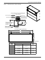
Precision Cooling
For Business-Critical Continuity™
Liebert® CW™
IBC Seismic Supplemental User Manual, 26-181kW, Upflow and Downflow
TABLE OF CONTENTS
IMPORTANT SAFETY INSTRUCTIONS . . . . . . . . . . . . . . . . . . . . . . . . . . . . . . . . . . . . . . . . . . . . . . . .1
SAVE THESE INSTRUCTIONS . . . . . . . . . . . . . . . . . . . . . . . . . . . . . . . . . . . . . . . . . . . . . . . . .1
1.0
LIEBERT CW NOMENCLATURE . . . . . . . . . . . . . . . . . . . . . . . . . . . . . . . . . . . . . . . . . . . . . .3
2.0
INTRODUCTION . . . . . . . . . . . . . . . . . . . . . . . . . . . . . . . . . . . . . . . . . . . . . . . . . . . . . . . . . .4
2.1
Background . . . . . . . . . . . . . . . . . . . . . . . . . . . . . . . . . . . . . . . . . . . . . . . . . . . . . . . . . . . . . . . . . 4
2.2
Determining Whether a Unit is IBC-Compliant . . . . . . . . . . . . . . . . . . . . . . . . . . . . . . . . . . . 4
2.3
Certification Criteria . . . . . . . . . . . . . . . . . . . . . . . . . . . . . . . . . . . . . . . . . . . . . . . . . . . . . . . . . 5
3.0
SITE REQUIREMENTS OF SEISMIC INSTALLATION . . . . . . . . . . . . . . . . . . . . . . . . . . . . . . . . .6
4.0
FLOOR AND FLOOR STAND SEISMIC MOUNTING . . . . . . . . . . . . . . . . . . . . . . . . . . . . . . . . .7
4.1
Anchoring Systems Without Floor Stand . . . . . . . . . . . . . . . . . . . . . . . . . . . . . . . . . . . . . . . . . 8
4.1.1
4.2
Floor-Anchoring Requirements for Seismic Installations . . . . . . . . . . . . . . . . . . . . . . . . . . . . . 8
Anchoring Systems With Floor Stand . . . . . . . . . . . . . . . . . . . . . . . . . . . . . . . . . . . . . . . . . . . . 9
4.2.1
4.2.2
4.2.3
Floor Stand Anchoring Requirements for Seismic Installations . . . . . . . . . . . . . . . . . . . . . . . . 9
Rigid and Rubber Isolated Floor Stand Anchoring. . . . . . . . . . . . . . . . . . . . . . . . . . . . . . . . . . 10
Spring-Isolated Floor Stand Anchoring. . . . . . . . . . . . . . . . . . . . . . . . . . . . . . . . . . . . . . . . . . . 11
5.0
ELECTRICAL CONSIDERATIONS OF SEISMIC INSTALLATION . . . . . . . . . . . . . . . . . . . . . . . . . 16
6.0
PIPING CONSIDERATIONS OF SEISMIC INSTALLATION . . . . . . . . . . . . . . . . . . . . . . . . . . . . . 18
6.1
Fluid Connections. . . . . . . . . . . . . . . . . . . . . . . . . . . . . . . . . . . . . . . . . . . . . . . . . . . . . . . . . . . 18
6.1.1
6.1.2
Condensate Piping—Field-Installed . . . . . . . . . . . . . . . . . . . . . . . . . . . . . . . . . . . . . . . . . . . . . 18
Humidifier Supply Water—Optional Infrared or Steam Generating Humidifier . . . . . . . . . 18
6.2
Chilled Water Piping . . . . . . . . . . . . . . . . . . . . . . . . . . . . . . . . . . . . . . . . . . . . . . . . . . . . . . . . 18
7.0
PLENUM AND DUCTING CONSIDERATION OF SEISMIC INSTALLATION . . . . . . . . . . . . . . . . . . 21
7.1
Plenum Installation . . . . . . . . . . . . . . . . . . . . . . . . . . . . . . . . . . . . . . . . . . . . . . . . . . . . . . . . . 21
7.2
Duct Connections . . . . . . . . . . . . . . . . . . . . . . . . . . . . . . . . . . . . . . . . . . . . . . . . . . . . . . . . . . . 22
8.0
ANCHOR AND LOAD REQUIREMENTS OF SEISMIC INSTALLATION . . . . . . . . . . . . . . . . . . . . 25
9.0
MAINTENANCE . . . . . . . . . . . . . . . . . . . . . . . . . . . . . . . . . . . . . . . . . . . . . . . . . . . . . . . . . 27
9.1
Seismic Bracing . . . . . . . . . . . . . . . . . . . . . . . . . . . . . . . . . . . . . . . . . . . . . . . . . . . . . . . . . . . . 27
9.1.1
Temporary Service Access . . . . . . . . . . . . . . . . . . . . . . . . . . . . . . . . . . . . . . . . . . . . . . . . . . . . . 27
9.2
Inspection of System Connections . . . . . . . . . . . . . . . . . . . . . . . . . . . . . . . . . . . . . . . . . . . . . . 27
9.3
Post-Seismic Inspection . . . . . . . . . . . . . . . . . . . . . . . . . . . . . . . . . . . . . . . . . . . . . . . . . . . . . . 28
i
FIGURES
Figure 1
Figure 2
Figure 3
Figure 4
Figure 5
Figure 6
Figure 7
Figure 8
Figure 9
Figure 10
Figure 11
Dimensional data—seismic anchoring. . . . . . . . . . . . . . . . . . . . . . . . . . . . . . . . . . . . . . . . . . . . . . .
Dimensional data—seismic anchoring of rigid floor stand . . . . . . . . . . . . . . . . . . . . . . . . . . . . . . .
Dimensional data—seismic anchoring of rubber-isolated floor stand . . . . . . . . . . . . . . . . . . . . . .
Dimensional data—seismic anchoring of spring-isolated floor stand . . . . . . . . . . . . . . . . . . . . . .
Electrical wiring—seismic considerations . . . . . . . . . . . . . . . . . . . . . . . . . . . . . . . . . . . . . . . . . . . .
Horizontal expansion loop . . . . . . . . . . . . . . . . . . . . . . . . . . . . . . . . . . . . . . . . . . . . . . . . . . . . . . . .
Vertical expansion loop . . . . . . . . . . . . . . . . . . . . . . . . . . . . . . . . . . . . . . . . . . . . . . . . . . . . . . . . . .
Piping—seismic considerations . . . . . . . . . . . . . . . . . . . . . . . . . . . . . . . . . . . . . . . . . . . . . . . . . . . .
Seismic mounting data—upflow and downflow plenums . . . . . . . . . . . . . . . . . . . . . . . . . . . . . . . .
Plenum hold-down clip dimensions . . . . . . . . . . . . . . . . . . . . . . . . . . . . . . . . . . . . . . . . . . . . . . . . .
Seismic duct connection considerations. . . . . . . . . . . . . . . . . . . . . . . . . . . . . . . . . . . . . . . . . . . . . .
12
13
14
15
17
19
19
20
22
23
24
TABLES
Table 1
Table 2
Table 3
Table 4
Table 5
Table 6
Table 7
Comparison of certification criteria, 2000-2006 . . . . . . . . . . . . . . . . . . . . . . . . . . . . . . . . . . . . . . . . 5
Downflow Liebert CW models on 36" floor stand without plenum . . . . . . . . . . . . . . . . . . . . . . . . 25
Downflow Liebert CW models on 36" floor stand with plenum . . . . . . . . . . . . . . . . . . . . . . . . . . . 25
Direct mount to concrete. . . . . . . . . . . . . . . . . . . . . . . . . . . . . . . . . . . . . . . . . . . . . . . . . . . . . . . . . . 26
Direct mount to concrete with plenum . . . . . . . . . . . . . . . . . . . . . . . . . . . . . . . . . . . . . . . . . . . . . . 26
Upflow Liebert CW models on 36" floor stand without plenum . . . . . . . . . . . . . . . . . . . . . . . . . . . 26
Upflow Liebert CW models on 36" floor stand with plenum . . . . . . . . . . . . . . . . . . . . . . . . . . . . . 26
ii
IMPORTANT SAFETY INSTRUCTIONS
This manual contains important safety and installation instructions not included in the Liebert CW
user manual (SL-18057). The information in this manual is not a substitute for the data in the Liebert
CW user manual, but provides additional information required for units equipped with the seismic
option. The information in this manual should be read carefully and used to ensure compliance with
the International Building Code. Special inspection per IBC Section 1704 is required during all installations. Read this document and the Liebert CW user manual, SL-18057, thoroughly before attempting to install or operate this unit.
Only properly trained and qualified personnel should move, install or service this equipment.
Adhere to all warnings, cautions and installation, operating and safety instructions on the unit, in the
Liebert CW user manual (SL-18057) and in this manual. Follow all operating and user instructions.
SAVE THESE INSTRUCTIONS
! WARNING
Risk of electric shock. Can cause injury or death.
Disconnect local and remote power supplies before working within.
Before proceeding with installation, read all instructions, verify that all the parts are included
and check the nameplate to be sure the voltage matches available utility power.
The Liebert iCOM™ microprocessor does not isolate power from the unit, even in the “unit
off” mode. Some internal components require and receive power even during the “unit off”
mode of the Liebert iCOM control.
The factory-supplied optional disconnect switch is inside the unit. The line side of this switch
contains live high-voltage. With disconnect off, check for voltage on load side.
The only way to ensure that there is NO voltage inside the unit is to install and open a remote
disconnect switch. Refer to unit electrical schematic.
Follow all local codes.
! WARNING
Risk of high-speed moving parts. Can cause injury or death.
Disconnect all local and remote electric power supplies before working in the unit.
Do not operate upflow units without installing a plenum, ductwork or guard over the blower
opening(s) on the top surface of the unit cabinet.
Ductwork must be connected to the blower(s), or a plenum must be installed on the blower
deck for protection from rotating blower wheel(s) on upflow units.
! WARNING
Risk of top-heavy unit falling over. Can cause equipment damage, injury or death.
Read all of the following instructions before attempting to move the unit, lift it, remove
packaging or prepare the unit for installation.
! WARNING
Risk of seismic event. Can cause equipment damage, injury or death.
Unit must be welded to the floor stand and anchored to the floor or housekeeping pad. If not
mounted on a floor stand, the unit must be anchored to the floor or housekeeping pad.
1
! CAUTION
Risk of sharp edges, splinters and exposed fasteners. Can cause injury.
Only properly trained and qualified personnel wearing appropriate safety headgear, gloves,
shoes and glasses should attempt to move the unit, lift it, remove packaging or prepare the
unit for installation.
! CAUTION
Risk of hazardous fumes. Can cause injury or death.
Welding may produce fumes and gases hazardous to health. Avoid breathing these fumes and
gases. Use adequate ventilation.
NOTICE
Risk of overhead interference. Can cause unit and/or building damage.
The unit may be too tall to fit through a doorway while on the skid. Measure the unit and
doorway heights and refer to the installation plans to verify clearances prior to moving the
unit.
NOTICE
Risk of damage from forklift. Can cause unit damage.
Keep tines of the forklift level and at a height suitable to fit below the skid and/or unit to
prevent exterior and/or underside damage.
NOTICE
Risk of improper storage. Can cause unit damage.
Keep the Liebert CW upright, indoors and protected from dampness, freezing temperatures
and contact damage.
NOTICE
Risk of leaking water. Can cause equipment and building damage.
This unit requires a water drain connection. It may also require an external water supply to
operate.
Improper installation, application and service practices can result in water leakage from the
unit. Water leakage can result in severe property damage and loss of critical data center
equipment.
Do not install this unit above equipment or machines that could be damaged by leaking water.
Do not install equipment or machines that could be damaged by leaking water below this unit.
Emerson recommends installing leak detection equipment for unit and supply lines.
NOTICE
Risk of structural damage. Drilling holes all the way through the floor or housekeeping pad
may cause damage to the structure and can result in damage to lower floors.
Drilling holes that penetrate either the floor or the housekeeping pad must be properly filled
and sealed.
2
Liebert CW Nomenclature
1.0
LIEBERT CW NOMENCLATURE
CW
114
CW = Liebert CW
Floor Mount
Chilled Water
Unit
D
C
S
D = Downflow
U = Upflow with Front
Return
XXX = Nominal
Capacity, kW
A
2
A = 460/3/60
B = 575/3/60
C = 208/3/60
D = 230/3/60
2 = 380/3/60
F = 380/3/50
G = 415/3/50
M = 380-415V/3/50 Hz
C = Chilled Water
S = Forward-Curved Centrifugal
Fan with Standard Motor
V = Forward-Curved Centrifugal
Fan with Variable Speed Drive
1 = EC Motorized Impeller
3
1234
A
XXXX
A-Z = Standard
configuration
S = SFA
2 = 2-Way Valve, Standard Pressure
3 = 3-Way Valve, Standard Pressure
1 = 2-Way Valve, High Pressure
T = 3-Way Valve, High Pressure
Introduction
2.0
INTRODUCTION
2.1
Background
The International Code Council’s International Building Code (IBC) is the primary code document for
the design and installation of building systems. This has brought about increased scrutiny of mechanical and electrical equipment that is used in the operation of facilities, particularly those buildings
designated as “essential facilities.” Previously, codes focused only on preventing equipment from
breaking free from anchoring and becoming projectiles, and did not consider its structural integrity.
These new codes, depending on the Use Group and Importance Factor of the building, may require
equipment to function after a seismic event.
IBC-2000, 2003, 2006 has made the manufacturer of mechanical and electrical equipment responsible
for designing, testing and certifying systems. Emerson, through a recognized Approved Agency, has
conducted analytical modeling and dynamic shake-table testing of the Liebert CW to provide an
option for those systems requiring seismic certification of compliance. The seismic shake-table testing
was conducted in accordance with ICC-ES AC-156. This certification goes beyond the equipment’s
ability to withstand seismic forces. The IBC system approach includes the equipment, equipment
anchoring and the connections to the equipment (power, water supply and return and ducting). In
essential applications the equipment must be capable of performing its primary function after a seismic event within the limit of certification.
NOTE
An approved agency is defined by IBC section 1702 as: An established and recognized agency
regularly engaged in conducting tests or furnishing inspection services, when such agency has
been approved.
2.2
Determining Whether a Unit is IBC-Compliant
The catalog Liebert CW unit is NOT IBC-compliant. To be IBC-compliant, units must be ordered with
the factory-installed seismic bracing option. Liebert CW units with the seismic bracing option will
have:
• Certification label—near the unit nameplate, behind the front panel
• Certificate of compliance—included in the customer envelope with this manual
• Factory-installed seismic bracing components
NOTE
Factory-installed seismic bracing components are painted red and must not be removed.
4
Introduction
2.3
Certification Criteria
Liebert CW units equipped with the seismic option are certified to a maximum Ss of 2.89g (2.89 times
the force of gravity), adjusted by the soil site coefficient to Soil Site Class D as the default when neither the site soil properties nor the final equipment installation location is known. The certification
maximum Sds value of 1.93g includes Soil Class and Seismic Use group corrections. Soil Classes A, B,
C, D, E, Seismic Use groups I, II, III, IV and Seismic Design Categories A, B, C, D, E and F are all covered under this certification, limited by the Sds value stated above.
A seismic importance factor, Ip, of 1.5 applies to this certification to include essential facility requirements and life-safety applications for the Liebert CW system’s functionality after a seismic event.
Shake-table testing conducted in accordance with ICC-ES AC-156 enveloped a required response
spectrum (RRS) defined by a maximum flexible region acceleration (AFLEX) of 3.08g and a zero period
acceleration (ARIG) of 2.32g.
Table 1
Comparison of certification criteria, 2000-2006
IBC 2006
IBC 2003
IBC 2000
Sds <=1.93
Sds <=1.93
Sds <=1.93
Ip <=1.5
Ip <=1.5
Ip <=1.5
ap/Rp <=1.25
ap/Rp <=1.0
ap/Rp <=1.0
z/h <=1.0
z/h <=1.0
z/h <=1.0
The Liebert CW, as described above, is approved for seismic application as a system when properly
installed in the following configurations:
• Liebert CW Unit, with factory-installed seismic option, attached directly to a housekeeping pad
using the anchoring system defined in this seismic installation instruction.
• Liebert CW Unit, with factory-installed seismic option and with factory-supplied plenum. Plenums must be flexibly attached to the duct system (if applicable). Unit and plenum must be
anchored as defined in this seismic installation instruction.
• Liebert CW Unit, with factory-installed seismic option, installed on an Emerson-supplied,
IBC-certified floor stand and attached securely to the building structure. The floor stand and
mounting system must be Emerson catalog items, purchased from Emerson. The system must be
anchored as specified in this seismic installation instruction.
• The certification excludes all non-Emerson supplied accessories, including but not limited to floor
stands, isolators and restraints. Use of non-Emerson accessories will void IBC certification of the
Liebert CW system.
5
Site Requirements of Seismic Installation
3.0
SITE REQUIREMENTS OF SEISMIC INSTALLATION
All floor and housekeeping pads must be approved by the structural engineer of record to resist the
added seismic loads from components being anchored as specified in 8.0 - Anchor and Load
Requirements of Seismic Installation. The concrete floor slab and concrete housekeeping pads
must be minimum 4000 psi compressive strength, normal-weight concrete. Concrete aggregate must
comply with ASTM C33. The floor and housekeeping pads must be designed and rebar-reinforced for
seismic applications in accordance with ACI 318. When anchoring the Liebert CW to a floor, rebar
interference must be considered.
The minimum housekeeping pad thickness must be the thickness required by the qualification report
for the selected post-installed anchor or 1.5 times the depth the anchor is embedded, whichever is
greater.
All housekeeping pads must be dowelled or cast into the building structural floor slab for seismic
application per ACI 318. When attaching the Liebert CW to the housekeeping pad, rebar interference
must be considered.
NOTE
Structural engineer of record is defined as: The registered design professional responsible for
the design of the designated seismic systems on the building construction documents.
NOTICE
Installation in structural, lightweight concrete is not permitted unless otherwise approved by
the structural engineer of record.
Contact your Emerson representative if a detailed Seismic Installation Calculation Package is
required. The information required to perform the calculations should include (but not be limited to):
Floor Data:
• Concrete compressive strength and aggregate content
• Slab or lightweight concrete over metal deck
• Thickness
• Type of reinforcement (rebar, wire mesh or none)
Housekeeping Pad:
• Concrete compressive strength and aggregate content
• Length, width and thickness
• Type of reinforcement (rebar, wire mesh or none)
• Doweled to floor or integrated
6
Floor and Floor Stand Seismic Mounting
4.0
FLOOR AND FLOOR STAND SEISMIC MOUNTING
Whether floor-mounted or installed on a floor stand, the Liebert CW must be anchored to the floor or
housekeeping pad. Field welding is required for seismic installations. In addition to the clearances
specified in the Liebert CW user manual, SL-18057, clearance is required behind the unit to prevent
damage to the equipment or building structure in a seismic event. Clearance requirements are dependent on the system mounting. Refer to 4.1 - Anchoring Systems Without Floor Stand and 4.2 Anchoring Systems With Floor Stand for recommendations.
The post-installed anchors used for unit anchoring must be pre-qualified for seismic applications in
accordance with ACI 335.2 and documented in a report by a reputable testing agency, such as the
Evaluation Service Report issued by the International Code Council. Anchors must be installed to the
torque specifications recommended by the anchor manufacturers to ensure maximum loading. Wide
washers, sized to match the nominal diameter of the specified anchors, must be used at each anchor
location. For tension load distribution the washer is to be placed between the anchor head and the
connected equipment. The washers are to be Type A, Series W plain washers per ANSI B18.22.1 1965, R1975.
The floor or housekeeping pad must be rebar-reinforced structural concrete that is seismically
designed and approved by the structural engineer of record to resist the added seismic loads from
components being anchored to the floor (see 3.0 - Site Requirements of Seismic Installation).
When installing anchors, rebar interference must be considered.
The installing contractor is responsible for the proper installation of all anchors and mounting hardware, observing the mounting requirement details outlined by the structural engineer of record.
NOTE
The floor stand used with EC units is not symmetrical, and its orientation to the Liebert CW is
critical to lowering the EC fans. Unless the floor stand is installed in the correct position, the
blowers will not lower into the floor stand.
7
Floor and Floor Stand Seismic Mounting
4.1
Anchoring Systems Without Floor Stand
Anchor brackets provided with the seismic option are to be welded to the base of the unit, flush to the
floor, at four locations. These brackets are included in the box of parts shipped with the Liebert CW.
! WARNING
Risk of high-speed moving parts. Can cause injury or death.
Disconnect all local and remote electric power supplies before working in the unit.
Do not operate upflow units without installing a plenum, ductwork or guard over the blower
opening(s) on the top surface of the unit cabinet.
Ductwork must be connected to the blower(s), or a plenum must be installed on the blower
deck for protection from rotating blower wheel(s) on upflow units.
! WARNING
Risk of top-heavy unit falling over. Can cause equipment damage, injury or death.
Read all of the following instructions before attempting to move the unit, lift it, remove
packaging or prepare the unit for installation.
! CAUTION
Risk of arc flash and infrared exposure during welding.
Only properly trained and qualified personnel wearing appropriate safety headgear, gloves,
shoes and eye protection should be welding.
! CAUTION
Risk of hazardous fumes and gases from welding equipment. Can cause choking and
respiratory-system injury or distress.
Only properly trained and qualified personnel wearing protective clothing, gloves, visor and
helmet should perform welding operations. Use adequate ventilation.
Clearances behind the unit of floor-mounted systems require only enough space to access the system
anchoring points.
4.1.1
Floor-Anchoring Requirements for Seismic Installations
• Unit directly mounted to structure:
• Four (4) half-inch diameter concrete expansion anchors
• Four (4) half-inch Type A, Series W plain washers
• Anchor selection must meet or exceed IBC 2000, 2003 and 2006 compliance requirements.
• All anchors listed and any housekeeping pad must be installed to meet compliance.
• Anchors must be installed per ICC ESR instructions.
• Special inspection per IBC Section 1704 is required on all installations.
See Figure 1 for anchor bracket weld and floor-anchoring details. Also see instructions provided with
the box of parts shipped with the Liebert CW unit, Seismic Part Package Field Installation Instructions for Liebert CW [195800].
NOTICE
Risk of structural damage. Drilling holes all the way through the floor or housekeeping pad
may cause damage to the structure and can result in damage to lower floors.
Drilling holes that penetrate either the floor or the housekeeping pad must be properly filled
and sealed.
8
Floor and Floor Stand Seismic Mounting
4.2
Anchoring Systems With Floor Stand
Units installed on floor stands must be welded to the floor stand as specified herein. Emerson provides a floor stand and mounting systems as selectable items that are IBC-certified and matched to
the Liebert CW.
The unit certification is valid only with the Emerson, IBC-certified, matched floor stand.
Clearances behind the unit of floor stand-mounted systems require space for access to the system
anchoring points and clearance for unit movement during a seismic event. The minimum space provided must be as indicated by dimension “Y” of Figure 11 for top of unit or top of plenum, depending
on the system configuration.
4.2.1
Floor Stand Anchoring Requirements for Seismic Installations
• 48- and 72-inch width units:
• Eight (8) concrete expansion anchors
• Eight (8) Type A, Series W plain washers
• 97- and 120-inch width units:
• Twelve (12) concrete expansion anchors
• Twelve (12) Type A, Series W plain washers
• Anchor selection must meet or exceed IBC 2000, 2003 and 2006 compliance requirements.
• All anchors listed and any housekeeping pad must be installed to meet compliance.
• Anchors must be installed per ICC ESR instructions.
• Special inspection per IBC Section 1704 is required on all installations.
NOTICE
Risk of structural damage. Drilling holes all the way through the floor or housekeeping pad
may cause damage to the structure and can result in damage to lower floors.
Drilling holes that penetrate either the floor or the housekeeping pad must be properly filled
and sealed.
NOTE
The seismic floor stand is not symmetrical, and its orientation to the Liebert CW unit is
critical. Unless the floor stand is installed in the correct position, features such as turning vane
and EC plug fans may not function properly.
9
Floor and Floor Stand Seismic Mounting
4.2.2
Rigid and Rubber Isolated Floor Stand Anchoring
See Figures 2 and 3 for weld and anchoring details.
1. Check the proposed finished floor height.
2. Turn the floor stand over and screw the feet/rubber isolator into the welded nut on the bottom
until the measurement from the bottom of the foot/isolator to the top surface of the upper tube
equals the finished floor height.
3. Turn the floor stand right side up.
4. If provided with turning vane, notch vane as required and attach it to the stand with #10 selfdrilling screws at 12" (30.5mm) centers. Spot welding is an acceptable alternative.
5. Place the floor stand in the final location in the correct orientation.
NOTE
The floor stand used with EC units is not symmetrical, and its orientation to the Liebert CW is
critical to lowering the EC fans. Unless the floor stand is installed in the correct position, the
blowers will not lower into the floor stand.
6. Level the stand by turning the foot/isolator up or down as necessary. Make sure all feet/isolators
are firmly resting on the floor.
7. Tighten foot/isolator jam nuts to prevent movement.
8. Mark foot/isolator hole locations on the floor or housekeeping pad. Remove floor stand and set
floor stand aside.
9. Drill holes and install anchors according to the manufacturer’s recommendations.
10. Set the floor stand into position over the anchor studs and tighten all hardware to the
manufacturer’s torque specifications.
11. Position the unit on the floor stand and weld the unit base to the floor stand gussets using a 1/8"
(3mm) continuous weld. See Figures 2 and 3.
! WARNING
Risk of top-heavy unit falling over. Can cause equipment damage, injury or death.
Read all of the following instructions before attempting to move the unit, lift it, remove
packaging or prepare the unit for installation.
! CAUTION
Risk of arc flash and infrared exposure during welding. Can cause injury.
Only properly trained and qualified personnel wearing appropriate safety headgear, gloves,
shoes and eye protection should be welding.
! CAUTION
Risk of hazardous fumes and gases from welding equipment. Can cause choking and
respiratory-system injury or distress.
Only properly trained and qualified personnel wearing protective clothing, gloves, visor and
helmet should perform welding operations. Use adequate ventilation.
10
Floor and Floor Stand Seismic Mounting
4.2.3
Spring-Isolated Floor Stand Anchoring
See Figure 4 for weld and anchoring details.
1. Check the proposed finished floor height.
2. Measure from the bottom of the floor stand isolator mounting location to the top surface of the
upper tube and add the spring isolator operating height, 7.13" (181mm). The finished floor height
should be no greater than this measurement. The floor stand height can be adjusted up no more
than 1/2" (12.5mm) by adding washers on the isolator studs above the adjusting nut before
placing the floor stand on the isolators. Adjustment down by no more than 1/8" (3mm) may be
done in Step 11.
3. If provided with a turning vane, notch the vane as required and attach it to the stand with #10
self-drilling screws at 12" (30.5mm) centers. Spot welding is an acceptable alternative.
4. Place the isolators in the final location per Figure 4.
5. Remove the jam nuts from the isolators and set them aside.
6. Set the floor stand into position over the isolator studs in the correct orientation. Place the jam
nuts on studs; do not tighten.
NOTE
The floor stand used with EC units is not symmetrical, and its orientation to the Liebert CW is
critical to lowering the EC fans. Unless the floor stand is installed in the correct position, the
blowers will not lower into the floor stand.
7. Mark the isolator hole locations on the floor or on the housekeeping pad. Remove the floor stand
and set it aside.
8. Drill the holes and install the anchors according to the manufacturer’s recommendations.
9. Set the floor stand into position over the anchor studs and tighten all hardware to the
manufacturer’s torque specifications.
10. Position the unit on the floor stand.
11. Adjust each isolator, turning the nut below the jam nut one full turn counterclockwise, in
sequence, until the isolator operating clearance of 1/4" (6mm) is achieved. See Figure 4 for
adjustment sequence.
12. Check to ensure that the equipment is level and adjust the isolators as required.
13. Tighten the jam nuts.
14. Weld the unit base to the floor stand gussets using a 1/8" (3mm) continuous weld. See Figure 4.
! WARNING
Risk of top-heavy unit falling over. Can cause equipment damage, injury or death.
Read all of the following instructions before attempting to move the unit, lift it, remove
packaging or prepare the unit for installation.
! CAUTION
Risk of arc flash and infrared exposure during welding. Can cause injury.
Only properly trained and qualified personnel wearing appropriate safety headgear, gloves,
shoes and eye protection should be welding.
! CAUTION
Risk of hazardous fumes and gases from welding equipment. Can cause choking and
respiratory-system injury or distress.
Only properly trained and qualified personnel wearing protective clothing, gloves, visor and
helmet should perform welding operations. Use adequate ventilation.
11
Floor and Floor Stand Seismic Mounting
Figure 1
Dimensional data—seismic anchoring
FIELD WELDING OF ANCHOR BRACKET
Typical 4 Places
1/8" (3mm)
1.8" (46mm) Minimum
Typical Both Sides
ANSI B18.22.1
Type A, Series W Plain
Washer Required At
Each Anchor Location
1/8" (3mm)
2.6"
(67mm)
Min. Embedment
4"(101.6mm)
Minimum Pad Thickness
1.5 Times Anchor Embedment
Per Anchor Qualification
Test Report
Minimum 4000 lb
Compressive Strength
Normal Weight Concrete
Min. Hole Depth
4.75" (120.7mm)
Minimum Edge Distance
6" (152.4mm)
FLOOR ANCHORING DIMENSIONS
A
10" (254mm)
B
Anchor Location
Typical 4 Places
34.9"
(886mm)
DPN001803
Model
Number
CW026
CW038
CW041
CW051
CW060
CW076
CW084
CW106
CW114
Dimensional Data, in. (mm)
A
B
Anchor
Size
48 (1219)
28 (711)
1/2"
72 (1829)
52 (1321)
1/2"
97 (2464)
77 (1956)
1/2"
120 (3048)
100 (2540)
1/2"
Anchor bolt sized per Hilti Kwik Bolt TZ carbon and stainless in concrete, ICC ESR-1917.
Alternates are subject to review by Emerson or structural engineer of record.
12
Floor and Floor Stand Seismic Mounting
Figure 2
Dimensional data—seismic anchoring of rigid floor stand
ANCHOR DETAIL
Typical 4 Places
ANSI B18.22.1
Type A, Series W Plain
Washer Required At
Each Anchor Location
Minimum Edge Distance
6" (152.4mm)
Min. Embedment
4"(101.6mm)
Minimum Pad Thickness
1.5 Times Anchor Embedment
Per Anchor Qualification
Test Report
Min. Hole Depth
4.75" (120.7mm)
FIELD WELDING OF UNIT TO FLOOR STAND
Unit Must Be Welded to Floor Stand to Maintain Certification
Typical 4 Places
Minimum 4000 lb
Compressive Strength
Normal Weight Concrete
1/8" (3mm)
8" (203mm)
FLOOR ANCHORING DIMENSIONS
A
B
1.9" (49mm)
1.9" (49mm)
5.5"
(140mm)
45°
31.5"
(800mm)
Front Gussets are
Flush With Top Tube
DPN001803
Model
Number
CW026
CW038
CW041
CW051
CW060
CW076
CW084
CW106
CW114
Dimensional Data, in. (mm)
A
B
Anchor
Size
46.5 (1181)
—
1/2"
70.5 (1791)
—
1/2"
95.5 (2426)
47.8 (1213)
1/2"
118.5 (3010)
31.5 (800)
1/2"
Anchor bolt sized per Hilti Kwik Bolt TZ carbon and stainless in concrete, ICC ESR-1917.
Alternates are subject to review by Emerson or structural engineer of record.
13
Floor and Floor Stand Seismic Mounting
Figure 3
Dimensional data—seismic anchoring of rubber-isolated floor stand
ANCHOR DETAIL
Typical 4 Places
Minimum Edge Distance
6" (152.4mm)
ANSI B18.22.1
Type A, Series W Plain
Washer Required At
Each Anchor Location
Min. Embedment
4"(101.6mm)
Minimum Pad Thickness
1.5 Times Anchor
Embedment Per Anchor
Qualification Test Report
Min. Hole Depth
4.75" (120.7mm)
Minimum 4000 lb
Compressive Strength
Normal Weight Concrete
FIELD WELDING OF UNIT TO FLOOR STAND
Unit Must Be Welded to Floor Stand to Maintain Certification
Typical 4 Places
1/8" (3mm)
8" (203mm)
FLOOR ANCHORING DIMENSIONS
A
1.9" (49mm)
B
1.9" (49mm)
5.5"
(140mm)
45°
31.5"
(800mm)
Front Gussets are
Flush With Top Tube
DPN001803
Model
Number
CW026
CW038
CW041
CW051
CW060
CW076
CW084
CW106
CW114
Dimensional Data, in. (mm)
A
B
Anchor
Size
46.5 (1181)
—
1/2"
70.5 (1791)
—
1/2"
95.5 (2426)
47.8 (1213)
1/2"
118.5 (3010)
31.5 (800)
1/2"
Anchor bolt sized per Hilti Kwik Bolt TZ carbon and stainless in concrete, ICC ESR-1917.
Alternates are subject to review by Emerson or structural engineer of record.
14
Floor and Floor Stand Seismic Mounting
Figure 4
Dimensional data—seismic anchoring of spring-isolated floor stand
ANCHOR DETAIL
Typical 6 Places
Jam Nut
.25" (4.4mm)
Operating
Clearance
Adjusting Nut
Minimum Edge Distance
6" (152.4mm)
.25" (4.4mm)
Operating
Clearance
ANSI B18.22.1
Type A, Series W Plain
Washer Required At
Each Anchor Location
Min. Embedment
4.75"(120.7mm)
Minimum Pad Thickness
1.5 Times Anchor
Embedment Per Anchor
Qualification Test Report
Min. Hole Depth
5.75" (146.1mm)
Minimum 4000 lb
Compressive Strength
Normal Weight Concrete
FIELD WELDING OF UNIT TO FLOOR STAND
Unit Must Be Welded to Floor Stand to Maintain Certification
Typical 4 Places
1/8" (3mm)
8" (203mm)
FLOOR ANCHORING DIMENSIONS
A
B
3
1 *
3.3"
(83mm)
5.4"
(137mm)
35°
5
3.8"
(95mm)
6.6"
(166mm)
2
Model
Number
CW026
CW038
CW041
CW051
CW060
CW076
CW084
CW106
CW114
35.25"
(895.4mm)
6
4
Dimensional Data, in. (mm)
Front Gussets are
Flush With Top Tube
* Isolator
Adjustment
Sequence
A
B
Anchor
Size
46.5 (1181)
—
3/4"
70.5 (1791)
—
3/4"
95.5 (2426)
47.8 (1213)
3/4"
118.5 (3010)
31.5 (800)
3/4"
Anchor bolt sized per Hilti Kwik Bolt TZ carbon and stainless in concrete, ICC ESR-1917.
Alternates are subject to review by Emerson or structural engineer of record.
15
DPN001803
Electrical Considerations of Seismic Installation
5.0
ELECTRICAL CONSIDERATIONS OF SEISMIC INSTALLATION
Input power and control wiring connections to the Liebert CW must be flexible and able to withstand
movement in three dimensions. Relative motion caused by a seismic event must be absorbed to prevent damage to the unit, building structure and wiring. It is recommended that all connections to the
unit be made as low as possible. The flexible connection should include at least one bend between the
unit connection location and the first clamping point at the foundation or structure. It must be of sufficient length to makeup for the maximum displacement indicated in Figure 5.
! WARNING
Risk of electric shock. Can cause injury or death.
Disconnect local and remote power supplies before working within.
Before proceeding with installation, read all instructions, verify that all the parts are included
and check the nameplate to be sure the voltage matches available utility power.
The Liebert iCOM™ microprocessor does not isolate power from the unit, even in the “unit off”
mode. Some internal components require and receive power even during the “unit off” mode of
the Liebert iCOM control.
The factory-supplied optional disconnect switch is inside the unit. The line side of this switch
contains live high-voltage. With disconnect off, check for voltage on load side.
The only way to ensure that there is NO voltage inside the unit is to install and open a remote
disconnect switch. Refer to unit electrical schematic.
Follow all local codes.
! WARNING
Risk of high-speed moving parts. Can cause injury or death.
Disconnect all local and remote electric power supplies before working in the unit.
Do not operate upflow units without installing a plenum, ductwork or guard over the blower
opening(s) on the top surface of the unit cabinet.
Ductwork must be connected to the blower(s), or a plenum must be installed on the blower
deck for protection from rotating blower wheel(s) on upflow units.
! WARNING
Risk of improper wiring, piping, moving, lifting and handling. Can cause equipment damage,
injury or death.
Installation and service should be done only by personnel who have been properly trained and
qualified in the installation of air conditioning equipment.
NOTICE
Risk of improper electrical supply connection. Can cause equipment damage during a seismic
event.
NOTICE
Risk of overheated terminals. Can cause wiring and component damage. Use copper wiring
only. Make sure that all connections are tight.
16
Electrical Considerations of Seismic Installation
Figure 5
Electrical wiring—seismic considerations
Field-supplied disconnect
switch when factory-installed
unit disconnect switch
is not provided
Seismic compensation
Three phase electrical and low voltage connections
not by Emerson (CW106U & CW114U ONLY)
Factory-installed unit disconnect switch (optional)
Monitoring
panel
UPFLOW MODELS
(INCLUDING CW106U & CW114U)
Z
X
Seismic
compensation
Y
Three phase electrical and low voltage
connections not by Emerson
Factory-installed unit
disconnect switch (optional)
Field-supplied disconnect
switch when factory-installed
unit disconnect switch
is not provided
NOTE:
Flexible conduit and conductors must be provided
to allow for movement of the unit in three dimensions
during a seismic event. The flexible conduit shall have
at least one bend between the rigid connection at the
unit cabinet and the connection to rigid conduit or
foundation. Allowances in table are for units installed
on unconstrained 36 inch (914mm) spring isolated
floor stands with 3 phase power and control connections
entering the unit at the unit base, above the lower third
of the unit (below the coil), and the unit top.
Monitoring
panel
DOWNFLOW MODELS
(INCLUDING CW106D & CW114D)
Z
X
Y
DPN001803
Three phase electrical and low voltage
connections not by Emerson
Seismic compensation
UNIT
DISPLACEMENT
Total
Displacement
X
Y
Z
Unit
base
Above base
24 in. (610mm)
Top
of unit
in.
mm
in.
mm
in.
mm
±3.3
±85
±4.8
±122
±9.5
±241
±1.7
±2.7
±1.0
±43
±69
±25
±2.5
±4.0
±1.0
±64
±102
±25
±5.0
±8.0
±1.0
±127
±203
±25
Displacements are for unit mounted on 36 in. (914mm) spring-isolated floor stand.
17
TOTAL DISPLACEMENT (TD)
[Vector sum of X, Y, Z displacements]
TD
Z
X
Y
Piping Considerations of Seismic Installation
6.0
PIPING CONSIDERATIONS OF SEISMIC INSTALLATION
All fluid connections to the unit must be flexible and able to withstand movement in three dimensions. Relative motion caused by a seismic event must be absorbed to prevent damage to the unit,
building structure and piping. It is recommended that all connections to the unit are made as low as
possible. The flexible connection should of sufficient length to make up for the maximum displacement indicated in Figure 8 and be securely clamped at the foundation or structure and the unit.
6.1
Fluid Connections
NOTICE
Risk of water leaks. Can cause unit and/or building damage. This unit requires a water drain
connection and an external water supply to operate.
Improper installation, application and service practices can result in water leakage from the unit.
Do not install this unit above equipment or machines that could be damaged by leaking water.
Do not install equipment or machines that could be damaged by leaking water below this unit.
Emerson recommends installing leak detection equipment for unit and supply lines.
6.1.1
Condensate Piping—Field-Installed
! CAUTION
Risk of boiling water. Can cause personal injury.
The unit requires a drain line that may contain boiling water. Only properly trained and
qualified personnel wearing appropriate safety equipment should service the drain line or
work on parts near or connected to the drain line.
Whether supplied with 3/4" NPT gravity drain connection or 1/2" copper sweat connection from a factory-installed condensate pump, the drain line of the unit will require a flexible element to permit
movement. When selecting a suitable flexible element consider the following:
•
•
•
•
•
6.1.2
The drain line may contain boiling water.
Drain is trapped internally. Do not trap external to the equipment.
Gravity drain line must be sized for 2 gpm (7.61 l/m) flow.
Condensate pump discharge sized based on available head.
Drain line must comply with all applicable codes.
Humidifier Supply Water—Optional Infrared or Steam Generating Humidifier
When selecting a suitable flexible element, permitting movement in three dimensions of sufficient
length to make up for the maximum displacement, consider the following:
• The humidifier supply connection is 1/4" copper line with a maximum water pressure of 150 psi
(1034kPa).
• Size the supply line for 1 gpm (3.8 l/m), with a minimum water pressure of 20 psi (138kPa).
6.2
Chilled Water Piping
The chilled water connections of the Liebert CW product, as with all connections, require a flexible
element permitting movement in three dimensions to avoid damage to the unit, structure or piping
system. Unlike the other fluid connections, the chilled water supply and return lines pose a unique
problem because of the sizes involved. Line sizes can be as large as 2-5/8" OD copper. For these connections, Emerson recommends flexible expansion loops. Loops typically consist of two flexible sections of convoluted stainless or bronze metallic hose with braided cover, two elbows and 180° return
section with or without support bracket. These loops minimize the seismic loads to the piping system
anchor points. Depending on the manufacturer, the connections to the loop are available in female
copper sweat, NPT thread, flange or grooved. Maximum displacements are indicated in Figure 8.
18
Piping Considerations of Seismic Installation
Figure 6
Horizontal expansion loop
Figure 7
Vertical expansion loop
Manual shutoff valves should be installed at the supply and return lines to each unit. This provides
for routine service and emergency isolation of the unit. To prevent water damage, install a water
detection system, such as a Liebert Liqui-tect® or floor drains with wet traps.
19
Piping Considerations of Seismic Installation
Figure 8
Piping—seismic considerations
Unit
Unit
Anchor piping
to unit
Secure pipes to floorstand
Prefabricated seismic
compensation piping
Anchor Piping
Prefabricated seismic
compensation piping
Z
Z
X
X
Y
Y
FLOOR MOUNT
Anchor to
foundation
FLOOR STAND MOUNT
Upflow with floorstand: anchor to floorstand
Upflow rigid mount: anchor to unit
Downflow: anchor to floorstand
Flexible Loops:
All units, either rigidly mounted or mounted on vibration isolators,
shall be attached to the piping system using flexible loops designed
for seismic movement. Flexible loops shall be capable of movement
in the ±X, ±Y, and ±Z planes and must completely isolate the
equipment from the piping. The loops shall be suitable for an
operating pressure and temperature of the system, refer to Emerson
installation instructions. This includes 1/4" copper humidifier supply,
condensate drainage, and chilled water supply and return. Follow
manufacturer’s installation instructions for proper seismic application
of flexible loops.
To unit
Seismic compensation device
FLEXIBLE LOOP EXAMPLE
DPN001803
UNIT
DISPLACEMENT
Total
Displacement
X
Y
Z
Above base
24 in. (610mm)
Unit base
in.
mm
in.
mm
±4.8
±122
±3.3
±85
±2.5
±4.0
±1.0
±64
±102
±25
±1.7
±2.7
±1.0
±43
±69
±25
Displacements are for unit mounted on 36 in. (914mm) spring-isolated floor stand.
20
TOTAL DISPLACEMENT (TD)
[Vector sum of X, Y, Z displacements]
TD
Z
X
Y
Plenum and Ducting Consideration of Seismic Installation
7.0
PLENUM AND DUCTING CONSIDERATION OF SEISMIC INSTALLATION
7.1
Plenum Installation
Liebert front/rear return plenums provided by Emerson are certified as part of the Liebert CW product. Seismic installations requiring top duct collar (TDC) plenums on Liebert CW051 and larger units
must use plenums specifically designed for the certified application. These plenums have additional
internal structure to meet the system’s IBC certification criteria.
Seismic-certified installation of Liebert plenums requires the addition of plenum hold-down clips to
secure the plenum on top of the unit. These clips must be installed inside the plenum and are
included in the box of ship-with parts provided with the Liebert CW unit.
1. Assemble the plenum following the assembly instructions provided with the plenum.
2. With the unit power OFF, lift the plenum and position it on top of the unit over the duct collar
provided.
3. See Figure 9 for clip installation details and Figure 10 for the number of clips and their
approximate fastening locations. Removal of the front/rear grill improves access for the
installation of plenum hold-down clips. Also see instructions provided with the box of parts
shipped with the Liebert CW unit, Seismic Part Package Field Installation Instructions for Liebert
CW [195800].
4. From inside the plenum, fasten the base of plenum to the top and top duct collar of the Liebert
CW unit using the appropriate clips for each side.
5. Hook the clip over the unit top duct collar and plenum edge and fasten in place as shown in
Figure 9. Install 1/4" self-drilling screws before the #8 screws.
6. Repeat Step 5 for the remaining clips (up to 12 locations).
! WARNING
Risk of improper plenum mounting. Can cause equipment damage, injury or death in a
seismic event.
! WARNING
Risk of high-speed moving parts. Can cause injury or death.
Disconnect all local and remote electric power supplies before working in the unit.
Do not operate upflow units without installing a plenum, ductwork or guard over the blower
opening(s) on the top surface of the unit cabinet.
Ductwork must be connected to the blower(s), or a plenum must be installed on the blower
deck for protection from rotating blower wheel(s) on upflow units.
! WARNING
Risk of top-heavy unit falling over. Can cause equipment damage, injury or death.
Read all of the following instructions before attempting to move the unit, lift it, remove
packaging or prepare the unit for installation.
NOTICE
All clips and fasteners are required to maintain IBC certification of conformity.
21
Plenum and Ducting Consideration of Seismic Installation
7.2
Duct Connections
Duct connections made to the unit or unit-mounted plenum must be connected with a flexible transition that will not transfer damaging loads to the unit or plenum. Connection must be sized to permit
movement of no less than the maximum displacement listed in the table of Figure 11.
NOTE
Special inspection per IBC section 1704 may be required on ductwork installation.
Figure 9
Seismic mounting data—upflow and downflow plenums
NOTE: Flanges provided
on blower(s) oulet for
supply air ducting when
solid panel plenum is used.
UPFLOW UNIT
Intermediate support
panel(s) provided on
IBC certified top duct
collar plenums only
(CW051 and higher)
Both top duct opening and
front grill are shown. See
specification sheet for
specific application.
PLENUM HOLD-DOWN CLIP DETAIL
(FRONT PANEL REMOVED FOR CLARITY)
1/4" self-drilling
screws through
clip into unit top
#8 self-drilling
screws through
clip, unit duct
collar and plenum
panel flange
DPN001803
All clips and fasteners are required to maintain IBC certification of conformity
NOTE: Flanges provided
on blower(s) oulet for
supply air ducting when
solid panel plenum is used.
DOWNFLOW UNIT
Intermediate support
panel(s) provided on
IBC certified top duct
collar plenums only
(CW051 and larger)
Both top duct opening and
front grill are shown. See
specification sheet for
specific application.
PLENUM HOLD-DOWN CLIP DETAIL
(FRONT PANEL REMOVED FOR CLARITY)
END CLIPS
FRONT CLIPS
#8 self-drilling
screws through
clip, unit duct
collar and plenum
panel flange
(typical all locations)
REAR CLIPS
1/4" self-drilling
screws through
clip into unit top
(typical front/rear)
All clips and fasteners are required to maintain IBC certification of conformity
22
DPN001803
Plenum and Ducting Consideration of Seismic Installation
Figure 10 Plenum hold-down clip dimensions
A
B
B
B
D
C
Number of Clips Required
Model #
End
Front/Rear
Total
A
B
C
D
2
2
8
7.4
(188)
31.2
(792)
6.5
(165.1)
19.0
(483)
2
3
10
7.4
(188)
27.6
(70.1)
6.5
(165.1)
19.0
(483)
2
4
12
7.4
(188)
26.7
(679)
6.5
(165.1)
19.0
(483)
2
4
12
7.4
(188)
34.4
(874)
6.5
(165.1)
19.0
(483)
CW026
CW038
CW041
CW051
CW060
CW076
CW084
CW106
CW114
Approximate Location, inches (mm)
All clips and fasteners are required to maintain IBC certification of conformity.
23
Plenum and Ducting Consideration of Seismic Installation
Figure 11 Seismic duct connection considerations
Seismic
compensation
Seismic
compensation
Z
Z
X
X
Y
Y
DOWNFLOW DUCTING EXAMPLE FOR SEISMIC APPLICATIONS
Seismic
compensation
Z
X
Y
Z
X
Seismic
compensation
Y
UPFLOW DUCTING EXAMPLE FOR SEISMIC APPLICATIONS
All ducted units, either rigidly mounted or mounted on vibration isolators, shall be attached to the ducting
system using flexible duct designed for seismic movement. Flexible loops shall be capable of movement in
the ±X, ±Y, and ±Z planes and must completely isolate the equipment from the duct work. The amount of
seismic movement is listed in the chart below. Refer to Liebert installation instructions for ducting
requirements. Follow manufacturer’s installation instructions for proper seismic application of flexible ducts.
DPN001803
UNIT
DISPLACEMENT
Total
Displacement
X
Y
Z
Above base
24 in. (610mm)
Top
of unit
Top
of plenum
in.
mm
in.
mm
in.
mm
±4.8
±122
±9.5
±241
±13.1
±333
±2.5
±4.0
±1.0
±64
±102
±25
±5.0
±8.0
±1.0
±127
±203
±25
±7.0
±11.0
±1.0
±178
±279
±25
Displacements are for unit mounted on 36 in. (914mm) spring-isolated floor stand.
24
TOTAL DISPLACEMENT (TD)
[Vector sum of X, Y, Z displacements]
TD
Z
X
Y
Anchor and Load Requirements of Seismic Installation
8.0
ANCHOR AND LOAD REQUIREMENTS OF SEISMIC INSTALLATION
All floor and housekeeping pads must be approved by the structural engineer of record to resist the
added seismic loads from components being anchored as defined in this section. Data is presented by
system configuration. The maximum system loads are given for each loading location or floor stand
foot. The maximum load at the anchor is provided for proper sizing of the anchors (not provided by
Emerson).
NOTE
The floor stand used with EC units is not symmetrical and its orientation to the Liebert CW is
critical to lowering the EC fans. Unless the floor stand is installed in the correct position, the
blowers will not lower into the floor stand.
NOTE
Load interactions must be considered when selecting anchors.
Downflow Liebert CW models on 36" floor stand without plenum
Anchors
Per Location
Maximum
Maximum
Load/Location Load/Anchor
Downflow
Liebert
CW
Restraint
Locations
Maximum
Maximum
Load/Location Load/Anchor
Spring - Isolated Floor Stand
Operating
Mass*
Maximum
Maximum
Load/Location Load/Anchor
Rubber - Isolated Floor Stand
Anchors
Per Location
Non-Isolated Floor Stand
Anchors
Per Location
Table 2
CW026D
899
4
508
250
397
125
2
1631
751
1341
375
2
1537
751
1866
375
2
CW038D
934
4
531
259
413
130
2
1702
778
1395
389
2
1605
778
1939
389
2
CW041D
984
4
571
270
440
135
2
1824
810
1479
405
2
1721
810
2044
405
2
CW051D
1261
4
618
339
503
169
2
2012
1016
1717
508
2
1892
1016
2431
508
2
CW060D
1326
4
667
353
535
176
2
2160
1058
1821
529
2
2034
1058
2563
529
2
CW076D
1479
6
504
272
407
136
2
1637
815
1389
407
2
1542
815
1961
407
2
CW084D
1665
6
567
306
458
153
2
1844
917
1564
458
2
1737
917
2208
458
2
Tension Shear Tension Shear
Tension Shear Tension Shear
Tension Shear Tension Shear
CW106D
2064
6
706
377
568
188
2
2257
1130
1920
565
2
2129
1130
2716
565
2
CW114D
2204
6
771
399
614
200
2
2461
1197
2069
599
2
2324
1197
2912
599
2
* Operating Mass includes the operating water volume and floor stand
Downflow Liebert CW models on 36" floor stand with plenum
Anchors
Per Location
Maximum
Maximum
Load/Location Load/Anchor
Downflow
Liebert
CW With
Plenum
Restraint
Locations
Maximum
Maximum
Load/Location Load/Anchor
Spring - Isolated Floor Stand
Operating
Mass*
Maximum
Maximum
Load/Location Load/Anchor
Rubber - Isolated Floor Stand
Anchors
Per Location
Non-Isolated Floor Stand
Anchors
Per Location
Table 3
CW026D
1054
4
1269
290
800
145
2
3930
869
2573
434
2
3819
869
3179
434
2
CW038D
1089
4
1315
299
828
149
2
4071
896
2663
448
2
3957
896
3288
448
2
CW041D
1139
4
1389
309
871
155
2
4294
928
2796
464
2
4174
928
3443
464
2
CW051D
1482
4
1621
397
1037
198
2
5042
1191
3354
595
2
4901
1191
4190
595
2
CW060D
1547
4
1709
411
1089
206
2
5308
1233
3517
617
2
5161
1233
4383
617
2
CW076D
1739
6
1281
313
819
157
2
3985
939
2650
470
2
3873
939
3309
470
2
CW084D
1925
6
1421
347
909
174
2
4423
1042
2941
521
2
4299
1042
3673
521
2
CW106D
2398
6
1762
435
1129
218
2
5447
1305
3637
653
2
5298
1305
4556
653
2
CW114D
2538
6
1883
458
1203
229
2
5818
1373
3870
686
2
5660
1373
4836
686
2
Tension Shear Tension Shear
Tension Shear Tension Shear
* Operating Mass includes the operating water volume, floor stand and plenum
** Plenum height 36" Top Duct Collar (TDC) or Front/Rear Discharge
25
Tension Shear Tension Shear
Anchor and Load Requirements of Seismic Installation
Direct mount to concrete
Table 5
Floor Mount Loads
Upflow
Liebert
CW
Shear
Anchors
Per
Location
Upflow
Liebert
CW
With
Plenum
727
226
1
755
235
1
Maximum
Load/Anchor
Operating
Mass*
Restraint
Locations
Tension
CW026U
811
4
CW038U
846
4
Direct mount to concrete with plenum
Floor Mount Loads
Maximum
Load/Anchor
Operating
Mass*
Restraint
Locations
Tension
Shear
Anchors
Per
Location
CW026U
967
4
1060
265
1
CW038U
1002
4
1089
274
1
CW041U
896
4
798
247
1
CW041U
1052
4
1131
286
1
CW051U
1152
4
812
330
1
CW051U
1372
4
1170
395
1
CW060U
1217
4
853
346
1
CW060U
1437
4
1211
411
1
CW076U
1393
4
857
385
1
CW076U
1653
4
1245
456
1
CW084U
1493
4
915
411
1
CW084U
1753
4
1303
482
1
CW106U
1891
4
1236
534
1
CW106U
2226
4
1716
621
1
CW114U
2031
4
1336
568
1
CW114U
2366
4
1815
655
1
* Operating Mass includes the operating water volume
Upflow Liebert CW models on 36" floor stand without plenum
Maximum
Maximum
Load/Location Load/Anchor
Upflow
Liebert
CW
Restraint
Locations
Maximum
Maximum
Load/Location Load/Anchor
Spring - Isolated Floor Stand
Operating
Mass*
Maximum
Maximum
Load/Location Load/Anchor
Rubber - Isolated Floor Stand
Anchors
Per Location
Non-Isolated Floor Stand
Anchors
Per Location
Table 6
* Operating Mass includes the operating water volume and plenum
** Plenum height 36" Top Duct Collar (TDC) or Front/Rear Discharge
Anchors
Per Location
Table 4
CW026U
907
4
1055
CW038U
942
4
1098
255
695
127
2
3391
764
2230
382
2
3292
CW041U
992
4
1161
268
733
134
2
3582
803
2353
401
2
3478
CW051U
1269
4
1387
351
894
176
2
4289
1054
2882
527
2
4168
1054
3625
527
2
CW060U
1334
4
1460
368
940
184
2
4511
1103
3027
551
2
4384
1103
3804
551
2
CW076U
1552
6
1122
287
725
143
2
3468
861
2337
430
2
3367
861
2942
430
2
CW084U
1652
6
1198
304
773
152
2
3700
913
2489
456
2
3593
913
3131
456
2
Tension Shear Tension Shear
245
668
122
2
Tension Shear Tension Shear
3260
734
2144
367
2
Tension Shear Tension Shear
3165
734
2656
367
2
764
2763
382
2
803
2912
401
2
CW106U
2070
6
1538
395
995
197
2
4739
1185
3199
592
2
4610
1185
4037
592
2
CW114U
2210
6
1656
417
1066
209
2
5101
1252
3427
626
2
4963
1252
4311
626
2
* Operating Mass includes the operating water volume and floor stand
Upflow Liebert CW models on 36" floor stand with plenum
Spring - Isolated Floor Stand
Upflow
Liebert
CW
With
Plenum
Restraint
Locations
Maximum
Maximum
Load/Location Load/Anchor
Operating
Mass*
Maximum
Maximum
Load/Location Load/Anchor
Anchors
Per Location
Rubber - Isolated Floor Stand
Anchors
Per Location
Non-Isolated Floor Stand
Maximum
Maximum
Load/Location Load/Anchor
Anchors
Per Location
Table 7
CW026U
1062
4
1407
284
866
142
2
4329
852
2761
426
2
4217
852
3355
426
2
CW038U
1097
4
1450
294
893
147
2
4460
882
2848
441
2
4345
882
3462
441
2
CW041U
1147
4
1512
307
931
153
2
4651
921
2970
460
2
4530
921
3611
460
2
CW051U
1489
4
1836
414
1155
207
2
5658
1243
3699
621
2
5517
1243
4574
621
2
CW060U
1554
4
1910
431
1201
215
2
5880
1292
3844
646
2
5733
1292
4754
646
2
CW076U
1812
6
1485
335
934
168
2
4573
1005
2990
503
2
4455
1005
3697
503
2
CW084U
1912
6
1561
352
982
176
2
4805
1057
3142
529
2
4681
1057
3886
529
2
CW106U
2405
6
1986
453
1252
227
2
6104
1360
4004
680
2
5954
1360
4965
680
2
CW114U
2545
6
2104
476
1324
238
2
6466
1427
4232
714
2
6307
1427
5239
714
2
Tension Shear Tension Shear
Tension Shear Tension Shear
* Operating Mass includes the operating water volume, floor stand and plenum
** Plenum height 36" Top Duct Collar (TDC) or Front/Rear Discharge
26
Tension Shear Tension Shear
Maintenance
9.0
MAINTENANCE
! WARNING
Risk of electric shock. Can cause injury or death.
Disconnect local and remote power supplies before working within.
Before proceeding with installation, read all instructions, verify that all the parts are included
and check the nameplate to be sure the voltage matches available utility power.
The Liebert iCOM™ microprocessor does not isolate power from the unit, even in the “unit off”
mode. Some internal components require and receive power even during the “unit off” mode of
the Liebert iCOM control.
The factory-supplied optional disconnect switch is inside the unit. The line side of this switch
contains live high-voltage. With disconnect off, check for voltage on load side.
The only way to ensure that there is NO voltage inside the unit is to install and open a remote
disconnect switch. Refer to unit electrical schematic.
Follow all local codes.
! WARNING
Risk of high-speed moving parts. Can cause injury or death.
Disconnect all local and remote electric power supplies before working in the unit.
Do not operate upflow units without installing a plenum, ductwork or guard over the blower
opening(s) on the top surface of the unit cabinet.
Ductwork must be connected to the blower(s), or a plenum must be installed on the blower
deck for protection from rotating blower wheel(s) on upflow units.
9.1
Seismic Bracing
Liebert CW units supplied with the seismic option can be easily identified once the panels are
removed. All seismic bracing is painted red and is factory-installed. Seismic bracing should not be
removed except when absolutely necessary. If any bracing is removed for service access, reinstall it
immediately after servicing unit.
9.1.1
Temporary Service Access
! WARNING
Risk of unit collapse. Can cause injury or death.
Braces are required for seismic certification. If removed for service access, reinstall brace
after servicing unit.
Seismic bracing is fastened to the unit frame with 1/4" self-drilling screws or bolts requiring a 3/8"
(10mm) wrench for removal. Units with plenums use #8 Phillips head, self-drilling screws in addition
to 1/4" self-drilling screws. Any bracing removed for service must be reinstalled and the 1/4" fasteners
must be tightened to 10 ft-lb. If a screw is stripped out, install a replacement at a new location within
1/2" (12mm) of the original location.
9.2
Inspection of System Connections
Check all connections to the system during routine maintenance and take appropriate action to correct any issues. System maintenance schedules must be established and performed.
27
Maintenance
9.3
Post-Seismic Inspection
Many areas of the country that are subject to seismic activity are working to draft local and national
guidelines and procedures for evaluating earthquake-damaged buildings and equipment. In 1989,
with funding from the California Office of Emergency Services, California Office of Statewide Health
Planning and Development and the Federal Emergency Management Agency, the Applied Technology
Council (ATC) published the ATC-20 Procedures for Post Earthquake Safety Evaluation of Buildings.
Inspections outlined in the document, may be required by areas that have adopted ATC-20 and must
be performed by a qualified individual.
The Liebert CW seismic certification of conformity is an assurance that the system will withstand a
seismic event occurring within the defined limits of 2.3 - Certification Criteria and continue to perform the primary function of cooling. Emerson requires an inspection of the system structure and connections by a registered professional engineer with five years of experience in anchorage design after
any significant seismic event greater than a magnitude 6.5 on the Richter Scale. This inspection will
apply to equipment within a 100 mile radius of the seismic event. If evidence of structural cracks,
yielding or loosening of structural members is found, the system must be replaced or restored to the
original design configuration.
28
Maintenance
NOTES
29
Maintenance
30
Ensuring The High Availability
Of Mission-Critical Data And Applications.
Emerson Network Power, the global leader in enabling business-critical
continuity, ensures network resiliency and adaptability through
a family of technologies—including Liebert power and cooling
technologies—that protect and support business-critical systems.
Liebert solutions employ an adaptive architecture that responds
to changes in criticality, density and capacity. Enterprises benefit
from greater IT system availability, operational flexibility and
reduced capital equipment and operating costs.
Technical Support / Service
Web Site
www.liebert.com
Monitoring
800-222-5877
[email protected]
Outside the US: 614-841-6755
Single-Phase UPS
800-222-5877
[email protected]
Outside the US: 614-841-6755
Three-Phase UPS
800-543-2378
[email protected]
Environmental Systems
800-543-2778
Outside the United States
614-888-0246
Locations
United States
1050 Dearborn Drive
P.O. Box 29186
Columbus, OH 43229
Europe
Via Leonardo Da Vinci 8
Zona Industriale Tognana
35028 Piove Di Sacco (PD) Italy
+39 049 9719 111
Fax: +39 049 5841 257
Asia
7/F Dah Sing Financial Centre
108 Gloucester Road
Wanchai
Hong Kong
852 2572 2201
Fax: 852 2519 9210
While every precaution has been taken to ensure the accuracy
and completeness of this literature, Liebert Corporation assumes no
responsibility and disclaims all liability for damages resulting from use of
this information or for any errors or omissions.
© 2009 Liebert Corporation
All rights reserved throughout the world. Specifications subject to change
without notice.
® Liebert is a registered trademark of Liebert Corporation.
All names referred to are trademarks
or registered trademarks of their respective owners.
SL-18058 _REV0_07-09
Emerson Network Power.
The global leader in enabling Business-Critical Continuity.
AC Power
Embedded Computing
Embedded Power
Connectivity
DC Power
Monitoring
Outside Plant
Power Switching & Controls
Precision Cooling
EmersonNetworkPower.com
Racks & Integrated Cabinets
Services
Surge Protection
Business-Critical Continuity, Emerson Network Power and the Emerson Network Power logo are trademarks and service marks of Emerson Electric Co.
©2009 Emerson Electric Co.