1
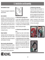
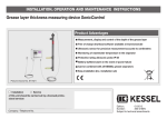
INSTALLATION, OPERATION AND MAINTENANCE INSTRUCTIONS
Alarm System with electronic sensor (Article number 20220) or
Alarm System with optical sensor (Article number 20221)
Product Advantages
Control unit splash proof (IP 54)
Usable with all KESSEL submersible pumps
Optical sensor alarm usable with conductive or non-conductive fluids
Electronic sensor alarm usable with conductive fluids
Quick and easy installation (assembly set included)
Picture shows No. 20 220
Installation
Service
of this unit should be carried out by a licensed professional
servicer:
Company / Telephone No.
Stamp Company
Edition:
08/2010
Number:
243-005EN
Subject to technical amendments
Table of contents
1. Safety Instructions
.......................................................................................................... Page
23
2. General
.......................................................................................................... Page
24
3. Installation and Assembly
3.1
3.2
3.3
3.4
3.5
3.6
Installation of the control unit ..............................................
Installation of sensor ............................................................
Remote alarm signalling device ...........................................
Potential free contact (BMS connection)..............................
Shortening of probe cable ..................................................
IInstallation / Cable connections ..........................................
Page
Page
Page
Page
Page
Page
25
26
26
26
26
27
4. Control unit
4.1
4.2
4.3
4.4
Connection plan ...................................................................
Commissioning ....................................................................
Operation .............................................................................
Changing to optical sensor ..................................................
Page
Page
Page
Page
29
29
30
30
5. Trouble shooting / Remedial actions
.......................................................................................................... Page
32
6. Technical data
.......................................................................................................... Page
34
7. Inspection / Maintenance
.......................................................................................................... Page
35
8. Warranty
.......................................................................................................... Page
36
9. Handover Certificate
.......................................................................................................... Page
37
22
1. Safety Instructions
Any personnel installing, operating, maintaining or repairing this system must have
the appropriate qualifications. The person
responsible for the system must assure that
anyone working on the system has the proper qualifications.
Proper and safe operation of the delivered
system can only be guaranteed if this installation and operational manual is complied with
The system operates on electrical current.
Noncompliance with the operating instructions may result in considerable damage to
property, personal injuries or even fatal accidents.
All local and international safety and accident prevention regulation should be followed including any appropriate DIN and VDE
norms and guidelines.
This alarm unit is a part of a complete system. Due to this please observe and comply with the installation and operational manual of the complete system and any other
components of the system. Prior to any installation, maintenance, inspection or repair
work on any of the system’s components all
power to the system must be disconnected
and secured against accidental re-connection during the work.
This system is not for installation or use in
an area which is considered an explosion
risk area.
When connected the control unit is being
supplied with power and must not be opened. Only licensed certified electricians
should handle electrical work on the system. The term certified electrician is defined in VDE 0105.
23
Make sure before placing the system into
operation that all electrical cables and other
electrical system are in perfect operating
condition. In the case that damaged is detected on any item, the system should not
be placed into operation and the damaged
should immediately be repaired.
Any changed made to the system must first
be authorized by the manufacturer. Original
replacement parts from the manufacturer or
manufacturer certified replacement parts
assure proper and safe operation. Use of
any other replacement parts could void the
guarantee as well as any damage claims
caused by failure of the non-certified part.
The system is to be supplied with a fault current protective device (RGD) with a continuous rated current of not more than 30 mA.
2. General
Dear customer,
We are pleased that you have decided to buy a KESSEL product.
The entire system was subjected to a stringent quality control before leaving the factory. Nevertheless, please check immediately whether
the system has been delivered to you complete and undamaged. In case of any transport damage, please refer to the instructions in the
chapter “Warranty” in this manual.
These installation, operating and maintenance instructions contain important information that has to be observed during assembly, operation, maintenance and repair. Prior to carrying out any work on the system, the operator and the responsible technical personnel must
carefully read and heed these installation and operating instructions.
Installation area of the Alarm Unit:
The Alarm unit monitors flooring or damage to pipes, machines, floor drains or backwater valves. The system is appropriate for use for
all conductive fluids such as wastewater, wastewater containing sewage, milk, leachate etc.
24
3. Installation and Assembly
3.1 Wall mounting of the control unit
Follow all safety instructions in Chapter 1
of the manual!
1
The control unit must be installed in a dry and
frost free area – preferable indoors where
any alarms and control unit message can be
seen / heard. Preferable is a wall mounted installation at eye level. As illustrated the control unit is fixed to the wall with the 4 included
dowels and M3.5 x 30 screws. A wall mounting template is included also.
햲 Hinge (x2)
햳 Plastic dowels (5x25mm (x4))
햴 Half rounded mounting screws
M3.5x30 (x4)
햵 Control unit cover screws (x4) max torque
1 Nm
4
1
2
3
25
Schematic control unit diagram without internal electric parts
3. Installation and Assembly
3.2 Installation of sensor
Fig. b
The sensor can be glued or dowelled in the
desired location
Glue installation
(Illustration b) The double side tape (5)
should be taped to the smooth side of the
small plate. Connect the small plate and the
holder (7) with the screws (8). Press the
entire assembly (with the open side of the
double sided tape) onto a clean preferably
smooth surface. The sensor (11) can now
be clipped into place.
Dowel installation
(Illustration b) Drill a 5 mm diameter hole in
the desired location and insert the dowel
(10). With the screw (9) secure the plate (6)
and the holder (7) to the wall.
Note concerning Alarm Unit 20221:
(Illustration b) The optical probe should be
installed in the holder in the horizontal position. Removing the grommets allows the
probe to reach the lowest possible level.
3.3 Remote alarm signalling device
A remote alarm (speaker)(Article Number
20162) can be purchased and connect to
the control unit. This alarm can be installed
in a nearby area or room where the audible
alarm is more likely to be heard.
3.4 Potential free contact (BMS connection)
A potential free contact (Article Number
80072) can be purchased and connected to
the control unit – for example for connection
to the Building Management System (BMS).
The 80072 circuit board can be connected
inside the control unit of the 20220 or the
20221 with the included plastic support feet
(Illustration 1). The board can now be clipped onto the four support feet (Illustrations
2 and 3).
26
3.5 Shortening of probe cable
The probe’s cable can be shortened if required. If the probe’s cables are cut it is recommended that the bare cables are coated
(with tin for example). If the bare cable ends
are equipped with a jacket, be sure to consider that the control unit jacks are designed for a connection of max 2.5 square
mm. The cross sectional area of 2.5 square
mm may not be exceeded.
1.
3.
2.
3. Installation and Assembly
3.6 Installation / Cable connections
The cables should be connected according
to the connection diagram (see Chapter 9).
As seen in Illustration a, first piece the gasket with a screw driver or sharp object. Now
insert the cable into the control unit housing
exactly as shown in Illustration b and inside
the control unit connect the bare cable ends
to the appropriate connection jacks as seen
in Illustration c. Now securely tighten the
locking nut as shown in Illustration d.
If the potential free contact (BMS connection) is to be installed, the technical specifications should be followed.
The sealing gaskets in any of the control unit’s
cable entrance holes should not be pierced.
This will assure that these connections remain
watertight even though they are not being
used.
Important:
All cables connected to the control unit
should secured so that in the event that a
cable comes loose that they do not cause a
27
danger. The probe cable should be laid separately from the control unit’s power cable
or motor cable.
3. Installation and Assembly
�
�
�
�
�
�
�
�
�
�
�
�
�
�
쐉
�
�
�
쐅 쐈
Illustration shows Article 20221
햲 Control unit housing
햳 Control unit cover screws (tight to max 1 Nm)
햴 Power cable
햵 Abbreviated operating instructions
햶 Power LED (green)
�
쐉
쐅쐈
Illustration shows Article 20220
햷 Alarm LED (red)
햸 Level LED (orange)
햹 Alarm button
햺 Potential free contact cable entrance
(Accessory – Article number 80072)
28
햻 Probe / sensor cable entranceoder
optische Sonde
햽 Remote alarm cable entrance
햾 Electronic probe (20220) or optical
probe (20221)
4. Control Unit
4.2 Commissioning
Please follow all safety instructions in
Chapter 1
4.1 Connection Plan
After all mechanical and electrical connections (including the 9-volt batteries located
inside the control unit) have been made,
commissioning of the system may begin.
•Plug in the control unit’s power chord to a
230V / 50 Hz outlet / power source
•The control unit will undergo a self check –
LEDs on the control unit will light from top
to bottom.
•The control unit will signal with an audible
tone
If all connections have been made correctly
the system will now be in normal operational
mode and the green LED light will be on.
In the case that the connections have been
made incorrectly an error message will be
displayed. If this is the case then disconnect
the control unit from it’s power source and
resolve the problem (see the trouble shooting section of this manual).
29
4. Control Unit
4.3 Operation
Alarm unit 20220
1
Alarm unit 20221
2
4.4 Changing to optical sensor (only to
be handled by a licensed certified electrician)
Alarm
Probe
Ader Nr. 1
Electronic
probe for conductive liquids
Alarm
2
Manual activation – when the system is in
normal operation, the ‘Alarm’ button on the
control unit can be pressed to test the visual
and audible alarms on the control unit.
Ader Nr. 1
2
3
Optical probe for
conductive and
non-conductive
liquids
Alarm
• Fluid level exceeds the ‘Alarm’ level
• An audible tone is sounded
• The red ‘Alarm’ LED lights
• The orange ‘Niveau / Level’ LED lights
• Fluid level falls below the ‘Alarm’ level
• Audible tone turns off
• The red ‘Alarm’ LED blinks as a notification
that the ‘Alarm’ level has been exceeded
(even if only for a short time)
• The orange LED ‘Nineau / Level’ is off.
20221 (for non-conductive fluids) if desired.
The optical sensor (accessory which will
need to be purchased) and the following
changes will be required:
• Disconnect the control unit from its power source
• Open the control unit cover and disconnect the batteries
• In the upper left hand corner of the control
unit, a bridge / jumper needs to be removed
• Disconnect and remove the electronic
probe
• Insert and connect the optical probe
• Close and tighten the control unit cover
• Reconnect the control unit to its power
source – the control unit will go through the
automatic check function.
Please make sure that the probe clips are
clipped in the correct position which will
assure that the probe cannot slip or become
dislodged.
30
Right
Installing the optical probe (20221) to the
KESSEL Aqualift F wastewater station:
• Remove the purple protection cap and insert the 20221 optical probe. Make sure
that the ‘eye’ (small protruding bulge) at
the end of the sensor is pointing toward the
pump. With a screw driver, secure the two
optical probe screws.
• Run the optical probe’s cable through the
conduit access and connect to the 20221
control unit as shown in the manual
• The probe clips / holder is not required for
this installation
In the case that the optical probe’s cable
needs to be extended, this can be done up
to a total final length of 30 meters (connection in accordance with VDE regulations).
4. Control Unit
Control unit display and operational buttons description
Display
Operational buttons
Button
LED
„Power“
„Alarm“
„Niveau/Level“
Color
green
red
orange
Duty
Power supply ok
Fluid exceeds Alarm level
Fluid exceeds Alarm level
„Alarm“
Turns off audible alarm,
Acknowledges warnings and faults
Checks the operational function of the audible and visual alarms and
the function of the potential free contact.
Warning displays
Optical probe/
Contact relay
Alarm level Exceeded
Optical probe /
Contact Relay
Alarm level exeeded
With power supply
potential free contact
LED
LED
„Power“
„Alarm“
tripped (on)
on
on
Power outage / back-up battery mode
potential free contact
LED
LED
„Power“
„Alarm“
tripped (on)
off
blinks every 2 s
31
LED
„NLevel“
on
audible
Alarm
on
remote
Alarm
on
LED
audible
„Level“
Alarm
blinks every 2 s on
remote
Alarm
on
5. Trouble Shooting / Remedial actions
Please follow the safety instructions in Chapter 1
Cancelling the audible alarm:
Cancelling the audible alarm:
The audible alarm can be turned off by pressing the ‘Alarm’ button on the control unit.
The visual alarm (LED) will however remain
active.
Resetting a failure warning:
Pre-requisites for resetting a failure warning
are:
• The audible alarm has been turned off
• The motor / pump is off
• The green Power LED is on and the red
Alarm LED is blinking
Pressing the ‘Alarm’ button for an extended
period of time will re-set the failure warning
The system is not back in normal operational mode.
• The Alarm level exceeded warning notifies
that the Alarm level has been exceeded,
even if only for an extremely short time period
• The Maximum allowable running time warning notifies that the activation / switching
level has not been reached after this time
period
• The Alarm level exceeded notification has
a higher priority as the maximum allowable
running time warning
32
Please check for proper cable connection of
the probe as well as short circuits or cut
cables.
5. Trouble Shooting / Remedial actions
Failure / warning displays
Potential free
contact Relay
tripped
(on)
• Battery missing, not activated or dead. Mains
230V power available
• No Mains 230V power tripped (on)
Problem
LED
LED
LED
„Power“ „Alarm“ „Level“
off
blinks
off
off
blinks
every 2
seconds
off
available, Batery pwer
available
with optical probe
• Probe cable is
connected improperly
or damaged
tripped (on)
off
blinks
blinks
alterna- alternatingly
tingly
33
audible
Alarm
on
remote
Alarm
on
on
on
on, audible on
alarm can
be turned
off
Remedial actions
• Disconnect control unit from Mains
power, check batteries and replace if
necessary.
• Re-connect control unit to 230 V
Mains power, check fusing
• Disconnect control unit from
Mains power. Check all control
unit connections and check probe
cable for damage.
6. Technical Data
General technical data
Control unit dimensions (L x W x H)
Control unit weight
Allowable surrounding temperature
Power use during stand by
Power use during activation
Protection class
Moisture protection class
Electrical connection for all copper
cables allowable
Allowable cable entrance diameter
into control unit
180 x 200 x 70mm
800 g
0 to 40 deg Celsius
14 mA
35 mA
II
IP 54
Power supply
Fusing
Probes
a) 2-finger electronic probe with
limited conductivity application
5–1000 uS / cm (with 3 meter
cable length)
or
b) optical probe with unlimited conductivity sensing
0.08 – 2.5 mm
5 to 9 mm
Power supply
Power supply
Inputs
230 V AC
1~50 Hz ± 10%L / N
European flat pin on con
trol unit with 1.2 mm
connection cable
max 10 Amp (fusing to be
handled on-site)
Outputs
Relay
Option:
Potential free contact
(Article number 80072)
/
• Changeover contact: Center
contact,
• Closing / Opening contact
• max. 42 VAC / 0,5 A
• With system internal fusing
• With system internal protective
switching for inductive loads
Option: Alarm warning dev. For connection of remote
(Article nr. 20162)
audible alarm
34
7. Inspection and maintenance
Please follow the safety instructions in Chapter 1 of the manual
If the control unit is to be cleaned it first must be completely disconnected from its power source. Control unit should be cleaned
with a soft cloth.
Repairs may only be handled by the manufacturer
The control unit required no maintenance, it is a maintenance free
item.
The probe(s) must be cleaned at regular intervals. This should be
done with a soft towel and water:
• Metal tips of the electronic probe should be free from any debris
or build-up.
• The plastic optical probe should also be cleaned and freed of any
debris or build-up.
All cables should be inspected for proper connection as well as for
damage. If a faulty connection or damage is detected, the control
unit should immediately be disconnected from its power source and
the repairs made as soon as possible.
Please do not scrape or scratch the probes as this can negatively
affect their operation.
35
8. Warranty
1. In the case that a KESSEL product is defective, KESSEL has the option of repairing or replacing the product. If the product remains defective after the second attempt to repair or replace the product or it
is economically unfeasible to repair or replace the product, the customer has the right to cancel the order / contract or reduce payment
accordingly. KESSEL must be notified immediately in writing of defects in a product. In the case that the defect is not visible or difficult
to detect, KESSEL must be notified immediately in writing of the defect as soon as it is discovered. If the product is repaired or replaced,
the newly repaired or replaced product shall receive a new warranty
identical to that which the original (defective) product was granted.
The term defective product refers only to the product or part needing
repair or replacement and not necessarily to the entire product or
unit. KESSEL products are warranted for a period of 24 month. This
warranty period begins on the day the product is shipped form KESSEL to its customer. The warranty only applies to newly manufactured products. Additional information can be found in section 377 of
the HGB.
In addition to the standard warranty, KESSEL offers an additional 20
year warranty on the polymer bodies of class I / II fuel separators,
grease separators, inspection chambers, wastewater treatment systems and rainwater storage tanks. This additional warranty applies
to the watertightness, usability and structural soundness of the product.
A requirement of this additional warranty is that the product is properly installed and operated in accordance with the valid installation
and user's manual as well as the corresponding norms / regulations.
2. Wear and tear on a product will not be considered a defect. Problems
with products resulting from improper installation, handling or maintenance will also not be considered a defect.
Note: Only the manufacturer may open sealed components or screw
connections. Otherwise, the warranty may become null and void
01.06.2010
36
9. Commissioning Protocol for installer
Type
________________________________________________________________
Day / Hour
________________________________________________________________
Project description /Building services supervisor____________________________________________________________
Address/ Telephone / Fax
________________________________________________________________
Builder
Address / Telephone / Fax
________________________________________________________________
________________________________________________________________
Planner
Address / Telephone / Fax
________________________________________________________________
________________________________________________________________
Contracted plumbing company
Address / Telephone / Fax
________________________________________________________________
________________________________________________________________
KESSEL-Commissions no.:
System operator /owner
Address / Telephone / Fax
________________________________________________________________
________________________________________________________________‘
________________________________________________________________
User
Address / Telephone / Fax
________________________________________________________________
________________________________________________________________
Person of delivery
________________________________________________________________
Other remarks
________________________________________________________________
The system operator, and those responsible, were present during the commissioning of this system.
_______________________
Place and date
____________________________
Signature owner
37
____________________________
Signature user
9. Handover-Ceritficate
Handover certificate (copy for the company carrying out the installation)
❏
The initial operation and instruction was carried out in the presence of the person authorised to perform the acceptance and the system operator.
❏
The system operator/person authorised to perform the acceptance was informed about the obligation to service the
product according to the enclosed operating instructions.
❏
Initial operation and instruction were not carried out.
The client/ person responsible for initial operation was handed the following components and/or product components
Initial operation and instruction is being carried out by (company, address, contact, phone)
The exact coordination of the dates for initial operation/instruction is being carried out by the system operator and person responsible for initial operation.
Place, date
Signature of person
authorised to perform acceptance
Signature of system operator
38
Signature of the company
carrying out the installation work
K Backwater protection
K Lifting Stations and pumps
K Drains and shower channels
K Separators
-Grease Separators
-Oil-/ Fuel-/Coalescence Separators
-Starch Separators
-Sediment Separators
K Septic Systems
K Inspection Chambers
K Rainwater Management Systems