1
Precision Cooling
For Business-Critical Continuity™
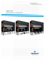
Liebert® CW™
System Design Manual - 26-181kW, 50 & 60Hz
TABLE OF CONTENTS
LIEBERT CW MODEL NUMBER NOMENCLATURE . . . . . . . . . . . . . . . . . . . . . . INSIDE FRONT COVER
1.0
LIEBERT CW PERFORMANCE DATA—50 & 60 HZ SYSTEMS . . . . . . . . . . . . . . . . . . . . . . . .2
2.0
LIEBERT CW PERFORMANCE DATA—MODELS WITH EC FANS, 50 & 60 HZ . . . . . . . . . . . .4
3.0
ELECTRICAL DATA—UNITS WITH EC FANS . . . . . . . . . . . . . . . . . . . . . . . . . . . . . . . . . . . . .5
3.1
CW106 and CW114 Electrical Data with EC Fans . . . . . . . . . . . . . . . . . . . . . . . . . . . . . . . . . 5
3.2
CW181 Electrical Data with EC Fans. . . . . . . . . . . . . . . . . . . . . . . . . . . . . . . . . . . . . . . . . . . . 5
4.0
DIMENSIONAL DATA . . . . . . . . . . . . . . . . . . . . . . . . . . . . . . . . . . . . . . . . . . . . . . . . . . . . . .6
5.0
UPFLOW DUCT CONNECTION DATA CW026—CW084 . . . . . . . . . . . . . . . . . . . . . . . . . . . 11
6.0
BLOWER DUCT & DECK DIMENSIONS, CW106 AND CW114, UPFLOW MODELS . . . . . . . . . 12
7.0
ELECTRICAL SPECIFICATIONS . . . . . . . . . . . . . . . . . . . . . . . . . . . . . . . . . . . . . . . . . . . . . . 13
8.0
GUIDE SPECIFICATIONS . . . . . . . . . . . . . . . . . . . . . . . . . . . . . . . . . . . . . . . . . . . . . . . . . . 16
FIGURES
Figure 1
Figure 2
Figure 3
Figure 4
Figure 5
Dimensions, CW026 - CW084. . . . . . . . . . . . . . . . . . . . . . . . . . . . . . . . . . . . . . . . . . . . . . . . . . . . . . . 6
Dimensional Data—50 & 60 Hz Systems CW106—CW114, downflow models . . . . . . . . . . . . . . . . 7
Cabinet and Floor Planning Dimensional Data, Downflow Model CW181 with EC Fans . . . . . . . 8
Cabinet and floor planning dimensions, upflow models—CW026-CW084 . . . . . . . . . . . . . . . . . . . 9
Cabinet and floor planning dimensions, CW 106 and CW114 upflow models. . . . . . . . . . . . . . . . 10
TABLES
Table 1
Table 2
Table 3
Table 4
Table 5
Table 6
Table 7
Table 8
Electrical data—60Hz-3 phase . . . . . . . . . . . . . . . . . . . . . . . . . . . . . . . . . . . . . . . . . . . . . . . . . . . . . . 5
Electrical data—50Hz-3 phase . . . . . . . . . . . . . . . . . . . . . . . . . . . . . . . . . . . . . . . . . . . . . . . . . . . . . . 5
CW181 electrical data—60Hz-3 phase. . . . . . . . . . . . . . . . . . . . . . . . . . . . . . . . . . . . . . . . . . . . . . . . 5
CW181 electrical data—50Hz-3 phase. . . . . . . . . . . . . . . . . . . . . . . . . . . . . . . . . . . . . . . . . . . . . . . . 5
Electrical data—50 Hz systems . . . . . . . . . . . . . . . . . . . . . . . . . . . . . . . . . . . . . . . . . . . . . . . . . . . . 13
Indoor evaporator fan motor electrical requirements—50Hz systems . . . . . . . . . . . . . . . . . . . . . 13
Electrical data—60 Hz Systems . . . . . . . . . . . . . . . . . . . . . . . . . . . . . . . . . . . . . . . . . . . . . . . . . . . . 14
Indoor evaporator fan motor electrical requirements—60Hz systems . . . . . . . . . . . . . . . . . . . . . 15
i
ii
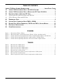
LIEBERT CW MODEL NUMBER NOMENCLATURE
CW
114
CW = Liebert CW
Floor Mount
Chilled Water
Unit
D
C
S
A
1234
A
Configuration
D = Downflow
U = Upflow
Nominal Capacity, kW
2
C = Chilled Water
A = 460/3/60
B = 575/3/60
C = 208/3/60
D = 230/3/60
2 = 380/3/60
F = 380/3/50
G = 415/3/50
S = Forward-Curved Centrifugal
Fan with Standard Motor
V = Forward-Curved Centrifugal
fan with Variable Speed Drive
1 = EC Motorized Impeller
1
A-Z = Standard
configuration
S = SFA
2 = 2-Way Valve, Standard Pressure
3 = 3-Way Valve, Standard Pressure
1 = 2-Way Valve, High Pressure
T = 3-Way Valve, High Pressure
Liebert CW Performance Data—50 & 60 Hz Systems
1.0
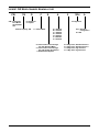
LIEBERT CW PERFORMANCE DATA—50 & 60 HZ SYSTEMS
CW026
CW038
CW041
CW051
CW060
CW076
CW084
CW106
CW114
Capacity Data BTU/Hr (kW) {Based on 45°F (7.2°C) Entering Water. 10°F (5.6°C) Water Rise}
80°F DB, 66.8°F WB (26.6°C DB, 19.3°C WB) 50% RH
Total - kBTUH (kW) 142 (41.7)
200 (58.7)
265 (77.5)
299 (87.6) 375 (110.0) 414 (121.3) 528 (154.7) 604 (176.9) 742 (217.4)
Sensible - kBTUH (kW) 110 (32.1)
144 (42.1)
175 (51.2)
218 (63.9)
254 (74.4)
295 (86.4) 351 (102.7) 421 (123.4) 486 (142.4)
Flow Rate - GPM (l/s) 29.9 (1.9)
42.4 (2.7)
55.3 (3.5)
63.5 (4.0)
78.8 (5.0)
88.4 (5.6)
111.3 (7.0)
128.0 (8.1)
155.5 (9.8)
Press. Drop - ft (kPa) 31.4 (93.7) 50.0 (149.2) 40.5 (120.9) 24.5 (73.1) 23.2 (69.2) 27.1 (80.9) 49.2 (146.8) 51.3 (153.1) 86.0 (256.6)
75°F DB, 62.5°F WB (23.9°C DB, 16.9°C WB) 50% RH
Total - kBTUH (kW) 96 (28.1)
137 (40.0)
186 (54.5)
199 (58.4)
255 (74.8)
281 (82.4) 366 (107.3) 414 (121.2) 524 (153.4)
Sensible - kBTUH (kW) 88 (25.7)
116 (34.0)
143 (41.9)
175 (51.2)
205 (60.2)
238 (69.6)
285 (83.6)
Flow Rate - GPM (l/s) 20.7 (1.3)
29.7 (1.9)
39.6 (2.5)
43.6 (2.8)
55.0 (3.5)
61.9 (3.9)
79.2 (5.0)
Press. Drop - ft (kPa) 15.6 (46.6) 25.3 (75.5)
22.0 (65.6) 12.1 (36.1) 12.0 (35.8) 14.0 (41.8) 26.3 (78.5)
341 (99.9)
398 (116.6)
90.2 (5.7)
111.9 (7.1)
26.8 (80.0) 46.8 (139.7)
75°F DB, 61°F WB (23.9°C DB, 16.1 °C WB) 45°% RH
Total - kBTUH (kW) 89 (26.2)
125 (36.6)
166 (48.7)
184 (54.0)
231 (67.8)
256 (75.1)
327 (95.9)
373 (109.4) 467 (136.9)
Sensible - kBTUH (kW) 89 (26.2)
118 (34.6)
144 (42.3)
179 (52.4)
209 (61.2)
242 (70.8)
289 (84.6)
347 (101.6) 402 (117.7)
Flow Rate - GPM (l/s) 19.4 (1.2)
27.4 (1.7)
35.6 (2.3)
40.6 (2.6)
50.2 (3.2)
56.9 (3.6)
71.0 (4.5)
Press. Drop - ft (kPa) 13.9 (41.5) 21.7 (64.8)
18.2 (54.3) 10.6 (31.6) 10.1 (30.1) 12.0 (35.8) 21.6 (64.5)
82.2 (5.2)
100.8 (6.4)
22.6 (67.4) 38.6 (115.2)
72°F DB, 60°F WB (22.2°C DB, 15.5°C WB) 50% RH
Total - kBTUH (kW) 75 (21.9)
106 (31.2)
146 (42.7)
155 (45.3)
200 (58.6)
218 (64.0)
285 (83.6)
322 (94.2)
411 (120.5)
Sensible - kBTUH (kW) 75 (21.9)
100 (29.4)
125 (36.6)
150 (43.9)
179 (52.4)
205 (60.0)
248 (72.8)
296 (86.7)
347 (101.8)
Flow Rate - GPM (l/s) 16.5 (1.0)
23.7 (1.5)
31.6 (2.0)
34.8 (2.2)
43.9 (2.8)
49.3 (3.1)
63.0 (4.0)
71.8 (4.5)
89.6 (5.7)
Press. Drop - ft (kPa) 10.2 (30.4) 16.5 (49.2)
14.6 (43.6)
7.9 (23.6)
7.9 (23.6)
9.3 (27.8)
17.3 (51.6)
17.6 (52.5)
31.1 (92.8)
72°F DB, 58.6°F WB (22.2°C DB, 14.8°C WB) 45% RH
Total - kBTUH (kW) 75 (21.9)
102 (29.9)
166 (48.7)
152 (44.4)
188 (55.0)
209 (61.1)
264 (77.3)
303 (88.7)
374 (109.5)
Sensible - kBTUH (kW) 75 (21.9)
102 (29.9)
144 (42.3)
152 (44.4)
183 (53.6)
209 (61.1)
254 (74.4)
303 (88.7)
355 (103.9)
Flow Rate - GPM (l/s) 16.4 (1.0)
22.8 (1.4)
35.6 (2.3)
34.2 (2.2)
41.5 (2.6)
47.4 (3.0)
58.7 (3.7)
68.1 (4.3)
82.2 (5.2)
Press. Drop - ft (kPa) 10.2 (30.4) 15.3 (45.7)
18.2 (54.3)
7.6 (22.7)
7.2 (21.5)
8.6 (25.7)
15.3 (45.7)
16.0 (47.7)
26.5 (79.1)
Hot-aisle Return Capacity Data, 45°F Entering Water, 12°F (6.6°C) Temperature Rise
85°F DB, 64.5°F WB (29.4°C DB, 18.1°C WB), 32.3% RH
Total - kBTUH (kW) 128 (37.4)
169 (49.6)
217 (63.7)
257 (75.2)
310 (90.7) 347 (101.7) 435 (127.5) 506 (148.3) 608 (178.2)
Sensible - kBTUH (kW) 128 (37.4)
169 (49.6)
201 (58.9)
257 (75.2)
295 (86.4) 347 (101.7) 405 (118.8) 492 (144.1) 559 (163.9)
Flow Rate - GPM (l/s) 22.5 (1.4)
30.1 (1.9)
38.2 (2.4)
45.9 (2.9)
54.8 (3.5)
Press. Drop - ft (kPa) 18.3 (54.6) 25.9 (77.3)
62.4 (4.0)
77.4 (4.9)
20.6 (61.5) 13.2 (39.4) 11.9 (35.5) 14.3 (42.7) 25.2 (75.2)
90.5 (5.7)
107.4 (6.8)
26.9 (80.3) 43.2 (128.9)
90°F DB, 66.2°F WB (32.2°C DB, 19.0°C WB), 27.7% RH
Total - kBTUH (kW) 151 (44.2)
198 (57.9)
249 (72.9)
302 (88.4) 357 (104.7) 405 (118.8) 500 (146.5) 587 (172.0) 695 (203.5)
Sensible - kBTUH (kW) 151 (44.2)
198 (57.9)
232 (67.9)
302 (88.4) 342 (100.2) 405 (118.8) 469 (137.3) 572 (167.7) 644 (188.7)
Flow Rate - GPM (l/s) 26.3 (1.7)
34.8 (2.2)
43.4 (2.7)
53.4 (3.4)
62.8 (4.0)
72.1 (4.6)
88.2 (5.6)
104.0 (6.6)
121.7 (7.7)
Press. Drop - ft (kPa) 24.5 (73.1) 34.2 (102.1) 26.0 (77.6) 17.6 (52.5) 15.2 (45.4) 18.6 (55.5) 32.0 (95.5) 34.8 (103.8) 54.5 (162.6)
95°F DB, 67.7°F WB (35°C DB, 19.8°C WB), 23.6% RH
Total - kBTUH (kW) 173 (50.8)
225 (66.0)
279 (81.8) 345 (101.2) 402 (117.9) 463 (135.6) 562 (164.8) 661 (193.7) 779 (228.1)
Sensible - kBTUH (kW) 173 (50.8)
225 (66.0)
262 (76.7) 345 (101.2) 388 (113.8) 463 (135.6) 531 (155.5) 653 (191.3) 727 (213.1)
Flow Rate - GPM (l/s) 30.1 (1.9)
39.5 (2.5)
48.5 (3.1)
60.6 (3.8)
70.2 (4.4)
81.7 (5.2)
98.6 (6.2)
116.3 (7.4)
135.6 (8.6)
Press. Drop - ft (kPa) 31.6 (94.3) 43.4 (129.5) 31.8 (94.9) 22.3 (66.5) 18.7 (55.8) 23.4 (69.8) 39.3 (117.3) 42.8 (127.7) 66.6 (198.7)
Unit capacity data is “net,” and is certified to ASHRAE 127-2007 rating standard
2
Liebert CW Performance Data—50 & 60 Hz Systems
CW026
CW038
CW041
CW051
CW060
CW076
CW084
CW106
CW114
Fan Section - Variable Pitch, Two-Belt Drive Package* (*Some options or combination of options may result in reduced air flow.
Consult factory for recommendation.)
5250
(8920)
6050
(10,280)
5900
(10,020)
9300
(15,800)
9100
(15,460)
12,500
(21,240)
12,100
(20,560)
17,100
(29,070)
16,500
(28,050)
Fan Motor HP (kW)
3.0 (2.2)
5.0 (3.7)
5.0 (3.7)
7.5 (5.6)
7.5 (5.6)
10 (7.5)
10 (7.5)
15 (11.2)
15 (11.2)
Ext. Static Press. in. of water (Pa)
0.2 (50)
0.2 (50)
0.2 (50)
0.2 (50)
0.2 (50)
0.2 (50)
0.2 (50)
0.2 (50)
0.2 (50)
1
1
1
2
2
2
2
3
3
11.7 (1.08)
11.7 (1.08)
11.7 (1.08)
18.5 (1.72)
18.5 (1.72)
25.0 (2.32)
25.0 (2.32)
3
4
6
4
6
4
6
4
6
431 (2.2)
499 (2.5)
486 (2.4)
482 (2.4)
471 (2.4)
484 (2.5)
480 (2.4)
471 (2.3)
460 (2.3)
Air Volume CFM (CMH)
Number of Fans
Chilled Water Coil
Face Area sq. ft. (m2)
Number of Rows
Face Velocity FPM (m/s)
36.28 (3.37) 36.28 (3.37)
Chilled Water Controls (Maximum design water pressure 150 PSI [1034.3 KPa]. Higher pressure available as an option. Consult factory.)
Valve Actuator Modulating
Modulating
Modulating
Modulating
Modulating
Modulating
Modulating
Modulating
Modulating
Sensors Proportional Proportional Proportional Proportional Proportional Proportional Proportional Proportional Proportional
Valve Body
Valve Cv
Valve Size - inches
2-Way Valve (0ptional)
Close Off Pressures-PSI (kPa)
3-Way
3-Way
3-Way
3-Way
3-Way
3-Way
3-Way
3-Way
3-Way
11.6
11.6
28.9
28.9
46.2
46.2
46.2
46.2
46.2
1
1-1/4
1-1/2
1-1/2
2
2
2
2
2
86 (593)
86 (593)
70 (483)
70 (483)
45 (310)
45 (310)
45 (310)
45 (310)
45 (310)
58,800 (15)
58,800 (15)
81,000 (20)
REHEAT SECTION
Electric Reheat: Three-Stage, Fin Tube
Capacity BTU/HR (kW)* 39,200 (10)
98,100 (25) 121,500 (30) 121,500 (30) 127,900 (30) 127,900 (30)
Steam Reheat: 218°F (103.3°C) Steam, 75°F (23.9°C) E.A.T., STD MTR-Modulating Control Valve 2-way****†
Capacity BTU/HR (kW)*
84,100
(24.6)
85,800
(25.1)
85,800
(25.1)
93,400
(27.4)
144,500
(42.4)
163,200
(47.8)
163,200
(47.8)
171,700
(50.3)
171,700
(50.3)
133,700
(39.2)
133,700
(39.2)
Hot Water Reheat: Capacity @ 180°F (82.2°C) E.W.T., STD MTR 75°F (23.8°C) E.A.T. - Modulating Control Valve 2-way****†
Capacity BTU/HR (kW)*
Flow Rate-GPM (l/s)
Pressure Drop-PSI (kPa)
47,000
(13.7)
49,500
(14.5)
49,500
(14.5)
89,900
(26.3)
89,900
(26.3)
125,200
(36.7)
125,200
(36.7)
5 (.31)
5 (.31)
5 (.31)
8 (.50)
8 (.50)
8 (.50)
8 (.50)
8 (.50)
8 (.50)
3.5 (24.1)
3.5 (24.1)
3.5 (24.1)
1.6 (11.0)
1.6 (11.0)
1.6 (11.0)
1.6 (11.0)
1.6 (11.0)
1.6 (11.0)
* Includes Fan Motor ** Optional 3-Way valve available-consult factory *** 25 PSI (172.4 kPa) Max operating pressure-consult factory for higher pressures.
† Unit CFM reduced by 300 with std. motor (142 l/s) **** 150 PSI (1034.3 kPA) Max operating pressure-consult factory for higher pressures.
HUMIDIFIER SECTION
Infrared Humidifier (Note: 50Hz Models are 22.1 lb/hr. (10.0 kg/h); 9.6 kW)
Capacity-lb/hr. (kg/h)
11.0 (5.0)
11 (5.0)
11.0 (5.0)
17.4 (7.9)„
17.4 (7.9)„
22.1 (10.0)
22.1 (10.0)
22.1 (10.0)
kW
4.8
4.8
4.8
6.4„
6.4„
9.6
9.6
9.6
22.1 (10.0)
9.6
Pan
Stainless
Stainless
Stainless
Stainless
Stainless
Stainless
Stainless
Stainless
Stainless
Steam Generating Humidifier (Water conductivity between 200-500 micromhos is required for ideal operation)
Capacity-lb/hr. (kg/h)
Capacity-kW
11 (5.0)
11 (5.0)
11.0 (5.0)
22 (10.0)
22 (10.0)
22 (10.0)
22 (10.0)
22 (10.0)
22 (10.0)
3.6
3.6
3.6
7.2
7.2
7.2
7.2
7.2
7.2
Steam Grid Humidifier - All Models (Standard Selection, 5 PSIG. (34.5 kPa) Steam 14 lb./hr. (6.4 kg/h)
Supply Steam Pressure,
PSIG (kPa)
—
2 (13.8)
4 (27.6)
5 (34.5)
6 (41.4)
8 (55.2)
10 (68.9)
—
—
Capacity-lb/hr. (kg/h),
w/ 5/32* orifice
—
8 (3.6)
12 (5.4)
14 (6.4)
16 (7.3)
19 (8.6)
21 (9.5)
—
—
Filter Section - Disposable Type - Nominal Sizes and Quantities, Downflow Models
Nominal Size, in
Quantity
18x24
18x24
18x24
18x24
18x24
18x24
18x24
24x31
24x31
4
4
4
6
6
8
8
5
5
24x24
24x24
24x24
24x24
24x24
24x24
24x24
18x24
18x24
2
2
2
3
3
4
4
10
10
Upflow Models (Front Return)
Nominal Size, in
Quantity
Upflow Models (Bottom & Rear Return) Bottom Return not available on CW106/CW114
Nominal Size, in
Quantity
18x24
18x24
18x24
18x24
18x24
18x24
18x24
18x24
18x24
4
4
4
6
6
8
8
10
10
2-5/8
CONNECTION SIZES
1-1/8
1-3/8
1-5/8
1-5/8
2-1/8
2-1/8
2-1/8
2-1/8
Infrared Humidifier-OD Copper
Chilled Water-OD Copper
1/4
1/4
1/4
1/4
1/4
1/4
1/4
1/4
1/4
Condensate Drain-FPT
3/4
3/4
3/4
3/4
3/4
3/4
3/4
1-1/4
1-1/4
Steam Reheat-MPT
1/2
1/2
1/2
1/2
3/4
3/4
3/4
3/4
3/4
Hot Water Reheat-OD Copper
5/8
5/8
5/8
7/8
7/8
7/8
7/8
7/8
7/8
Steam Humidifier-MPT
1/2
1/2
1/2
1/2
1/2
1/2
1/2
1/2
1/2
Weight-lb (kg)- Installed
810 (367)
845 (383)
895 (406)
1140 (517)
1210 (549)
1390 (630)
1490 (676)
1950 (885)
2090 (949)
3
Liebert CW Performance Data—Models with EC Fans, 50 & 60 Hz
2.0
LIEBERT CW PERFORMANCE DATA—MODELS WITH EC FANS, 50 & 60 HZ
CW106D
CW114D
CW181D
Capacity Data BTU/Hr (kW) {Based on 45°F (7.2°C) Entering Water. 10°F Water Rise}
75°F DB, 62.5°F WB (23.9°C DB, 16.9°C WB) 50% RH *
Total -kBTUH (kw)
435 (127.5)
552 (161.7)
Sensible - kBTUH (kw)
813 (238.2)
362 (106.1)
423 (123.9)
612 (179.3)
Flow Rate-GPM (Vs)
92.1 (5.8)
116.3 (7.4)
179.3 (11.4)
Press. Drop- ft (kPa)
27.8 (83.0)
50.2 (149.8)
40.0 (119.4)
75°F DB, 61°F WB (23.9°C DB, 16.1 °C WB) 45°% RH *
Total -kBTUH (kw)
395 (115.7)
494 (144.7)
725 (212.4)
Sensible - kBTUH (kw)
368 (107.8)
427 (125.1)
617 (180.8)
Flow Rate-GPM (Vs)
84.0 (5.8)
104.8 (6.6)
153.4 (9.7)
Press. Drop- ft (kPa)
23.5 (70.1)
41.5 (123.8)
29.3 (87.4)
72°F DB, 60°F WB (22.2°C DB, 15.5°C WB) 50% RH *
Total -kBTUH (kw)
341 (99.9)
435 (127.5)
642 (188.0)
Sensible - kBTUH (kw)
316 (92.6)
371 (108.7)
537 (157.3)
Flow Rate-GPM (Vs)
73.4 (4.6)
93.2 (5.9)
136.8 (8.7)
Press. Drop- ft (kPa)
18.3 (54.6)
33.4 (99.7)
23.3 (69.5)
72°F DB, 58.6°F WB (22.2°C DB, 14.8°C WB) 45% RH *
Total -kBTUH (kw)
323 (94.6)
395 (115.7)
586 (171.7)
Sensible - kBTUH (kw)
323 (94.6)
378 (110.8)
546 (160.0)
Flow Rate-GPM (Vs)
69.6 (4.4)
85.2 (5.4)
125.7 (8.0)
Press. Drop- ft (kPa)
16.6 (49.5)
28.3 (84.4)
19.7 (58.7)
17,600 (29,920)
17,360 (29,512)
24,000 (40,800)
Fan Motor hp Max, (kW), ea, qty 3
4.2 (3.4)
4.2 (3.4)
5.2 (4.3)
Ext. Static Press. in. of water (Pa)
0.2 (50)
0.2 (50)
0.2 (50)
36.3 (3.4)
36.3 (3.4)
71.2 (6.6)
4
6
6
471 (2.3)
471 (2.3)
337 (1.6)
46.2
46.2
46.2 qty2
2
2
2
102,390 (30)
102,390 (30)
102,390 (30)
22.1 (10.0)
22.1 (10.0)
22.1 (10.0)
9.6
9.6
9.6
Fan Data
Air Volume CFM (CMH)
Chilled Water Coil
Face Area sq. ft. (m2)
No. of Rows
Face Velocity FPM (m/s)
Valve Cv
Valve Size - inches
Electric Reheat - Three (3) Stage, Fin Tube
Capacity BTU/HR (kW)
Infrared Humidifier
Capacity-Lb. Per Hr. (kg/h)
kW
FILTER SECTION - DISPOSABLE TYPE - Nominal Sizes and Quantities, MERV7 or MERV11 (option)
Nominal Size, in
Quantity
24"x31"
24"x31"
21-1/2" x 24"
5
5
10
2-1/8
2-5/8
3-1/8
1/4
1/4
1/4
2090 (949)
2800 (1271)
CONNECTION SIZES
Chilled Water-O.D. Copper
Infrared Humidifier-O.D. Copper
Condensate Drain-FPT
1-1/4
Weight-lb (kg)- Installed
1950 (885)
* Unit capacity data is “net,” and is certified to ASHRAE 127-2007 rating standard
4
Electrical Data—Units with EC Fans
3.0
ELECTRICAL DATA—UNITS WITH EC FANS
3.1
CW106 and CW114 Electrical Data with EC Fans
Table 1
Reheat
Humidifier
Volts
FLA
WSA
OPD
Electric
Infrared
460
65.4
81.8
90
Electric
Infrared
575
53.4
66.8
70
Electric
Infrared
460
53.8
67.3
70
Electric
Infrared
575
41.8
52.3
60
None
Infrared
460
26.3
32.9
35
None
Infrared
575
23.3
29.1
30
None
None
460
14.7
15.9
20
None
None
575
11.7
12.7
15
Table 2
3.2
Electrical data—60Hz-3 phase
Electrical data—50Hz-3 phase
Reheat
Humidifier
Volts
FLA
WSA
Electric
Electric
400
70.8
88.5
Electric
None
400
58
72.5
None
Electric
400
27.5
34.4
None
None
400
14.7
15.9
CW181 Electrical Data with EC Fans
Table 3
CW181 electrical data—60Hz-3 phase
Reheat
Humidifier
Volts
FLA
WSA
OPD
Electric
Infrared
460
69
86.3
90
Electric
Infrared
575
56.4
70.5
80
Electric
None
460
57.4
71.8
80
Electric
None
575
44.8
56
60
None
Infrared
460
29.9
37.4
35
None
Infrared
575
26.3
32.9
35
None
None
460
18.3
19.8
25
None
None
575
14.7
15.9
20
Table 4
CW181 electrical data—50Hz-3 phase
Reheat
Humidifier
Volts
FLA
WSA
Electric
Electric
400
74.4
93
Electric
None
400
61.6
77
None
Electric
400
31.1
38.9
None
None
400
18.3
19.8
5
Dimensional Data
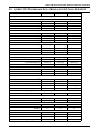
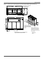
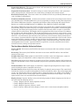
4.0
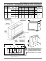
DIMENSIONAL DATA
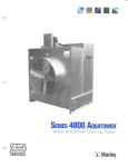
Figure 1
Dimensions, CW026 - CW084
J
Projection of
Display Bezel
3/4" (19mm)
nsion
Overall Dime
C
D
turn
Air Re g
Openin
2" (50.8mm)
Overa A
ll D
Unit A imension
nd Ple
num
Air Re B
turn O
penin
g
2"
(50.8mm)
J
A
Overall
Dimens
ion
C
Unit An
d Plenu
binet
m
Unit Ca
1"
F
Plenum
(25.4mm)
rall
on
Dimensi
Overall
Projection of
Display Bezel
3/4" (19mm)
1"
)
(25.4mm
72"
(1829mm)
Ove
K
Air Re B
turn O
penin
g
n
Air Retur
Opening
1"
)
(25.4mm
2"
(50.8mm)
Pre-Filter
Plenum
F as e
B
Unit Dimensional Data
3"
(76.2mm)
1"
(25.4mm)
Reheat or Humidifier
Piping Opening
(Optional Steam and
Hot Water Only)
G
Models With Pre-Filters
Air Discharge
Opening
H
1" (25.4mm)
20" (5
72"
(1829mm)
it
Un
F
9" (228mm)
1"
)
(25.4mm
Un E
it B
as
e
Shaded areas
indicate a recommended
clearance of 36" (914mm)
for component access
and filter removal.
9"
(228mm)
)
08mm
1"
(25.4mm)
Standard Piping
E
and Electrical Opening
DPN001659
Rev. 0
18"
(457mm)
Fl
oo
rL
ev
el
Floor Cutout Dimensions
Dimensional Data. inches (mm)
Model
A
B
C
D
E
F
G
H
J
K
Net Weight
lb (kg)
CW026
50
(1270)
50
(1270)
50
(1270)
74
(1880)
74
(1880)
99
(2515)
99(2515)
46
(1168)
46
(1168)
46
(1168)
70
(1778)
70
(1778)
95
(2413)
95
(2413)
35
(889)
35
(889)
35
(889)
35
(889)
35
(889)
35
(889)
35
(889)
32
(813)
32
(813)
32
(813)
32
(813)
32
(813)
32
(813)
32
(813)
48
(1219)
48
(1219)
48
(1219)
72
(1829)
72
(1829)
97
(2464)
97
(2464)
33
(883)
33
(883)
33
(883)
33
(883)
33
(883)
33
(883)
33
(883)
8
(203)
8
(203)
8
(203)
8
(203)
8
(203)
15 1/4
(387)
15 1/4
(387)
37
(940)
37
(940)
37
(940)
61
(1549)
61
(1549)
78 3/4
(2000)
78 3/4
(2000)
35-5/8
(905)
35 5/8
(905)
35 5/8
(905)
35 5/8
(905)
35 5/8
(905)
35 5/8
(905)
35 5/8
(905)
31
(787)
31
(787)
31
(787)
31
(787)
31
(787)
31
(787)
31
(787)
760
(345)
795
(361)
855
(388)
1090
(494)
1115
(524)
1320
(599)
1420
(644)
CW038
CW041
CW051
CW060
CW076
CW084
6
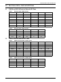
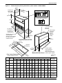
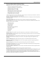
Dimensional Data
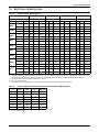
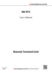
Figure 2
Dimensional Data—50 & 60 Hz Systems CW106—CW114, downflow models
G
Overall Dimension
Projection of
Display Bezel
3/4" (19mm)
Overall
C
D
turn
Air Re g
Openin
2" (50.8mm)
Air R
A
Dimen
sion
B
eturn
Open
ing
G
2"
(50.8mm)
Overall
ion
Dimens
Projection of
Display Bezel
3/4" (19mm)
76"
(1930mm)
A
Overall
Dimen
sio
Unit an
d Plenu n
m
C
1"
(25.4mm)
binet
Unit Ca
m
u
n
Ple
ll
Overa
H
Air Re B
turn O
pening
turn
Air Re g
in
Op e n
2" (51mm)
Pre-Filter
Plenum
Un E
it B
as
e
Shaded area
indicates a recommended
clearance of 36" (914mm)
for component access
and filter removal
F se
a
it B
n
U
1"
(25.4mm)
76"
(1930mm)
UNIT DIMENSIONAL DATA
F
20"
(508mm)
Air Discharge
Opening
m)
5.4m
2
(
1"
77" (1955.8mm)
E
MODELS WITH PRE-FILTERS
26"
(660.4mm)
28" )
mm
(711
Standard Piping
Opening
10"
(254mm)
*Electrical
Opening
(
Note: Electrical opening is also
used for drain connection of optional
steam generating canister humidifie r.
1"
(25.4mm)
)
"
24 m m
9 .6
0
6
1"
(25.4mm)
6"
(152.4mm)
*This drawing pertains to CW106 and CW 114
16-1/4"
with forward-curve blowers onl y.
(412.75mm)
DPN001660
Rev. 0
FLOOR CUTOUT DIMENSIONS
Dimensional Data, inches (mm)
Model
CW106
CW114
2"
(50.8mm)
9"
(228mm)
A
B
C
D
E
F
G
H
I
122
(3099)
118
(2997)
35
(889)
31
(787)
120
(3048)
33
(838)
35-5/8
(905)
30
(762)
34
(864)
7
Net Weight
lb (kg)
1785
(810)
1925
(873)
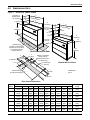
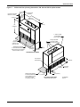
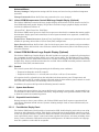
Dimensional Data
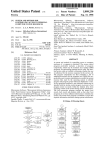
Figure 3
Cabinet and Floor Planning Dimensional Data, Downflow Model CW181 with EC Fans
Note: Electrical connections
can be made from the
bottom of the unit.
118"
(2997mm) Opening
47"
39-1/2" (1194mm)
(1003mm)
Opening
3/4"
(19mm) Bezels
TOP VIEW
122"
(3099mm)
36"
(914mm)
24"
(610mm)
76"
(1930mm)
1-1/2"
(38mm)
Striated area indicates the
recommended minimum
clearance for component
access.
Shaded area indicates the
required minimum clearance
120"
below the unit to lower the
(3048mm)
fans. Fans may also remain in
FRONT VIEW
unit if desired.
Note: Dimensions do not include filter plenum
DPN001694
shipped separate and field-Ainstalled.
REV 0
8
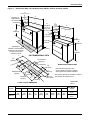
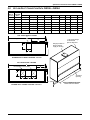
Dimensional Data
Figure 4
Cabinet and floor planning dimensions, upflow models—CW026-CW084
Projection Of
Display Bezel
3/4" (19mm)
35-5/8"
)
(905mm
Overall
on
Dimensi
A
Overall
Dimen
sion
35"
m)
8
(8 9m
Duct Flanges on 2 Blowers
H
1"
(25.4mm)
J
K
J
M
L
Front of Unit
Duct Flanges on One Blower
72"
(1829mm)
H
J
K
Front of Unit
Air grille may
be supplied on
units with front
or rear return air
B
Un
it B
Shaded areas indicate
a recommended
clearance of 36" (914mm)
for component access
and filter removal.
1" (25.4mm) Flange
for Plenum
Connection
Note: Flanges
provided on
blower(s)
outlet for
supply air
ducting.
1"
"
33 m)
(25.4mm)
8m
(83
Unit Base
as
e
1"
(25.4mm)
Unit Dimensional Data
33" m)
8m
(83
2"
/8"
1-1 m)
m
6
.
(28
5-1/2"
(139.7mm)
2 m)
9m
5
( 5
B
Air Return
Opening
G
Air Return
Opening
C
1
CW038
1
CW041
1
CW051
2
CW060
2
CW076
2
CW084
2
E
Models With Rear Return
Fl
oo
rL
ev
el
Models With Bottom Return
CW026
Ai
F
Floor Cutout Dimensions
No. of
Model Blowers
D
n
ur
et
R
r
ng
ni
pe
O
A return air grille
may be ordered in
place of the duct
flange. See specification
sheet for option supplied.
DPN001661
Rev. 0
Dimensional Data, inches (mm)
A
B
C
D
E
F
G
H
J
K
L
50
(1270)
50
(1270)
50
(1270)
74
(1880)
74
(1880)
99
(2515)
99
(2515)
48
(1219)
48
(1219)
48
(1219)
72
(1829)
72
(1829)
97
(2464)
97
(2464)
46
(1168)
46
(1168)
46
(1168)
70
(1778)
70
(1778)
95
(2413)
95
(2413)
44
(1118)
68
(1727)
44
(1118)
44
(1118)
68
(1727)
86
(2184)
86
(2184)
3
(76)
3
(76)
3
(76)
3
(76)
3
(76)
6-1/2
(165)
6-1/2
(165)
5
(127)
5
(127)
5
(127)
4
(102)
4
(102)
5
(127)
5
(127)
18
(457)
18
(457)
18
(457)
20
(508)
20
(508)
18
(457)
18
(457)
15-7/8
(403)
15-7/8
(403)
15-7/8
(403)
15-7/8
(403)
15-7/8
(403)
15-7/8
(403)
15-7/8
(403)
18-5/8
(473)
18-5/8
(473)
18-5/8
(473)
14-5/8
(371)
14-5/8
(371)
18-5/8
(473)
18-5/8
(473)
2-3/16
(55)
2-3/16
(55)
2-3/16
(55)
2-3/16
(55)
2-3/16
(55)
3 1/4
(82)
3 1/4
(82)
17-3/8
(454)
17-3/8
(454)
17-3/8
(454)
20-3/8
(517)
20-3/8
(517)
20-5/8
(524)
20-5/8
(524)
9
M
—
—
—
11-1/4
(286)
11-1/4
(286)
12-5/8
(321)
12-5/8
(321)
Net Weight,
lb (kg)
760
(345)
795
(361)
855
(388)
1090
(494)
1155
(524)
1320
(599)
1420
(644)
Dimensional Data
Figure 5
Cabinet and floor planning dimensions, CW 106 and CW114 upflow models
Projection of Display
Bezel 3/4" (19mm)
2" (51mm)
35" Overall
(889mm)
32"
(813mm)
Plenum
Flange
122" Overall
(3099mm)
118"
(2997mm)
Plenum Flange
2"
(51mm)
76"
(1930mm)
1" (25mm) flange
for decorative
plenum alignment
Flanges provided
on blower outlets
for supply air ducting.
Air grille
supplied on
units with front
return air only
Shaded areas indicate
a recommended clearance
of 36" (914mm) for component
access and filter removal.
120" Base
(3048mm)
1"
(25mm)
33" Base
(838mm)
Unit Dimensional Data
Filter Access
(Both Ends)
24-1/4" (616mm)
117-1/2"
(2985mm)
Shaded area indicates
a recommended clearance
of 25" (635mm) for rear
return filter removal
on one end of the unit.
4" (102mm)
2-1/4"
(57mm)
22" (546mm)
Duct Connection Data
Models With Rear Return
10
Air Return
Opening
DPN001662
REV 0
Upflow Duct Connection Data CW026—CW084
5.0
UPFLOW DUCT CONNECTION DATA CW026—CW084
No. of
Blowers
Model No.
Chilled
Water
Dimensional Data—in. (mm)
1
CW026
15-7/8 (403) 18-5/8 (473) 2-3/16 (55) 17-7/8 (454)
-
50 (1270) 35 (889) 44 (1118) 18 (457)
1
CW038
15-7/8 (403) 18-5/8 (473) 2-3/16 (55) 17-7/8 (454)
-
50 (1270) 35 (889) 44 (1118) 18 (457)
1
CW041
15-7/8 (403) 18-5/8 (473) 2-3/16 (55) 17-7/8 (454)
-
50 (1270) 35 (889) 44 (1118) 18 (457)
2
CW051
15-7/8 (403) 14-5/8 (371) 2-3/16 (55) 20-3/8 (517) 11-1/4 (288) 74 (1880) 35 (889) 68 (1727) 20 (508)
2
CW060
15-7/8 (403) 14-5/8 (371) 2-3/16 (55) 20-3/8 (517) 11-1/4 (288) 74 (1880) 35 (889) 68 (1727) 20 (508)
2
CW076
15-7/8 (403) 18-5/8 (473) 3-1/4 (82) 20-5/8 (524) 12-5/8 (321) 99 (2515) 35 (889) 86 (2184) 18 (457)
2
CW084
15-7/8 (403) 18-5/8 (473) 3-1/4 (82) 20-5/8 (524) 12-5/8 (321) 99 (2515) 35 (889) 86 (2184) 18 (457)
A
B
TOP- FRONT SUPPLY SHOWN
F
Duct flanges on one blower
C
D
E
F
G
H
J
C
D
A
G
Flange provided on
blower outlet for
supply air ducting
1" (25.4"mm) flange
for decorative
plenum alignment
B
FRONT OF UNIT
BLOWER DUCT FLANGE LOCATION - One Fan
TOP- FRONT SUPPLY SHOWN
C
F
Duct flanges on two blowers
J
D
A
G
B
E
H
B
4" (102mm)
FRONT OF UNIT
BLOWER DUCT FLANGE LOCATION - Two Fans
11
Air Return
Opening
DUCT CONNECTION DATA
Models with Rear Return
Blower Duct & Deck Dimensions, CW106 and CW114, Upflow Models
6.0
BLOWER DUCT & DECK DIMENSIONS, CW106 AND CW114, UPFLOW MODELS
Model
CW106
Blower
Supply
Motor,
hp
Top Front
Net Weight
lb. (Kg)
A
B
C
D
E
F
10-15
27-1/2
(699)
3 1/2
(89)
18-11/16
(475)
16-3/16
(411)
10
(254)
4 1/2
(114)
Top Rear
10-15
27-1/2
(699)
12 5/16
(313)
18 11/16
(475)
16 3/16
(411)
10
(254)
4 1/2
(114)
Top Front
10-15
30
(762)
3 1/2
(89)
14 3/4
(375)
16 3/16
(411)
10
(254)
4 1/2
(114)
20
30
(762)
3 1/2
(89)
14 3/4
(375)
16 3/16
(411)
10
(254)
4 1/2
(114)
10-20
30
(762)
12 5/16
(313)
14 3/4
(375)
16 3/16
(411)
10
(254)
4 1/2
(114)
15 x 15
CW114
Dimensional Data, inches (mm)
15 x 11
Top Rear
Flanges Provided on
Blower Outlets for
Supply Air Ducting
1785
(810)
1925
(873)
Top of Unit
1" (25.4mm) Flange
for Decorative
Plenum Alignment
Blower Deck
F
TOP-FRONT
SUPPLY SHOWN
76"
Ref
Filter
Access
(both
ends)
Front or Rear Air Supply
DPN001663
Rev. 0
24-1/4" (616mm)
Air
Return
Opening
117-1/2"
(2985mm)
4"
(102mm)
2
NOTE: Only 120"
2-1/4"
Upflow has rear
(57mm)
return filter box.
22"
(546mm)
1
122" Ref
Duct Flanges on Three Blowers
A
B
D
35"
Ref
C
E
C
E
1. Straight section of duct off of unit to be 1.5
to 2.5 times the longest blower dimension.
2. Typical ducting shown, may run to either
side.
*Follow standard practices on all duct work.
C
Front of Unit
Blower Duct Flange Location
12
Electrical Specifications
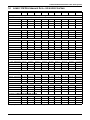
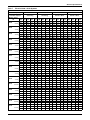
7.0
Table 5
ELECTRICAL SPECIFICATIONS
Electrical data—50 Hz systems
Reheat Options
Electric
None
Electric
None
Humidifier Options
IR/SGH
IR/SGH
Steam or None
Steam or None
Models
CW026
CW038
CW041
CW051
CW060
CW076
CW084
CW106
CW114
Motor HP Volts
200
230
380-415 200 230 380-415
200
230
380-415 200 230 380-415
2.0
FLA
46.7
43.4
24.3
19.8 17.2
9.9
33.9
32.3
17.9
7.0
6.1
3.5
3.0
FLA
49.8
46.1
25.9
22.9 19.9
11.5
37.0
35.0
19.5
10.1
8.8
5.1
3.0
FLA
62.9
59.0
33.2
22.9 19.9
11.5
50.1
47.9
26.8
10.1
8.8
5.1
5.0
FLA
68.6
63.9
36.0
28.6 24.8
14.3
55.8
52.8
29.6
15.8 13.7
7.9
3.0
FLA
62.9
59.0
33.2
22.9 19.9
11.5
50.1
47.9
26.8
10.1
8.8
5.1
5.0
FLA
68.6
63.9
36.0
28.6 24.8
14.3
55.8
52.8
29.6
15.8 13.7
7.9
5.0
FLA
94.6
88.4
49.6
41.2 35.9
20.7
69.2
66.2
36.8
15.8 13.7
7.9
7.5
FLA
103.9
96.5
54.2
50.5 44.0
25.3
78.5
74.3
41.4
25.1 21.8
12.5
5.0
FLA
107.9 101.4
56.8
41.2 35.9
20.7
82.5
79.2
44.0
15.8 13.7
7.9
7.5
FLA
117.2 109.5
61.4
50.5 44.0
25.3
91.8
87.3
48.6
25.1 21.8
12.5
7.5
FLA
126.6 122.6
68.6
50.5 44.0
25.3
101.2 100.4
55.8
25.1 21.8
12.5
10.0
FLA
131.7 128.4
71.2
55.6 49.8
27.9
106.3 106.2
58.4
30.2 27.6
15.1
7.5
FLA
126.6 122.6
68.6
50.5 44.0
25.3
101.2 100.4
55.8
25.1 21.8
12.5
10.0
FLA
131.7 128.4
71.2
55.6 49.8
27.9
106.3 106.2
58.4
30.2 27.6
15.1
10.0
FLA
131.7 128.4
71.2
55.6 49.8
27.9
106.3 106.2
58.4
30.2 27.6
15.1
15.0
FLA
147.1 142.4
78.9
71.0 63.8
35.6
121.7 120.2
66.1
45.6 41.6
22.8
20.0
FLA
161.5 152.8
86.1
85.4 74.2
42.8
136.1 130.6
73.3
60.0 52.0
30.0
10.0
FLA
131.7 128.4
71.2
55.6 49.8
27.9
106.3 106.2
58.4
30.2 27.6
15.1
15.0
FLA
147.1 142.4
78.9
71.0 63.8
35.6
121.7 120.2
66.1
45.6 41.6
22.8
20.0
FLA
161.5 152.8
86.1
85.4 74.2
42.8
136.1 130.6
73.3
60.0 52.0
30.0
1. FLA = FULL LOAD AMPS
2. Amperage requirements are based on the rated max FLA current of each component in the unit. The rated max FLA current of the unit is
not the sum total of all components, but is the total of the components which operate during maximum electrical load conditions.
3. The values in the table are for power demand of the unit only.
4. Units are 3-phase, 50-cycle.
5. Consult factory engineering department for electrical requirements of units with variations not listed above.
Table 6
Indoor evaporator fan motor electrical requirements—50Hz systems
Hp
Volts
200
230
380-415
2.0
FLA
7.0
6.1
3.5
3.0
FLA
10.1
8.8
5.1
5.0
FLA
15.8
13.7
7.9
7.5
FLA
25.1
21.8
12.5
10.0
FLA
30.2
27.6
15.1
15.0
FLA
46.2
42.0
24.2
20.0
FLA
NA
NA
30.0
1. Refer to General Data Section for standard fan motor size on units.
2. FLA = Full Load Amps
13
Electrical Specifications
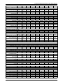
Table 7
Electrical data—60 Hz Systems
Chilled Water Models - 60Hz
Reheat Options
Humidifier Options
Models / Motor
HP
CW026
CW026
CW038
CW038
CW041
CW041
CW051
CW060
CW076
CW076
CW084
CW084
CW106
CW106
Volts
FLA
WSA
2.0 HP
MFCB
FLA
WSA
3.0 HP
MFCB
FLA
WSA
3.0 HP
MFCB
FLA
WSA
5.0 HP
MFCB
FLA
WSA
3.0 HP
MFCB
FLA
WSA
5.0 HP
MFCB
FLA
WSA
5.0 HP
MFCB
FLA
7.5 HP WSA
MFCB
FLA
5.0 HP WSA
MFCB
FLA
7.5 HP WSA
MFCB
FLA
7.5 HP WSA
MFCB
FLA
WSA
10.0 HP
MFCB
FLA
7.5 HP WSA
MFCB
FLA
WSA
10.0 HP
MFCB
FLA
10.0 HP WSA
MFCB
FLA
WSA
15.0 HP
MFCB
Electric
None
Electric
Electric
Infrared or Steam
Generating
Infrared or Steam
Generating
Steam or None
Steam or None
208
230
460
575
208
230
460
575
208
230
460
575
208
230
460
575
48.6
60.8
60
51.7
64.6
60
65.5
81.9
90
71.6
89.5
90
65.5
81.9
90
71.6
89.5
90
98.8
123.5
125
106.3
132.9
125
112.7
140.9
150
120.2
150.3
150
129.9
162.4
175
136.5
170.6
175
129.9
162.4
175
136.5
170.6
175
136.5
170.6
175
151.9
189.9
200
44.1
55.1
50
46.9
58.6
50
59.8
74.8
80
65.4
81.8
80
59.8
74.8
80
65.4
81.8
80
89.9
112.4
110
96.7
120.9
110
102.9
128.6
125
109.7
137.1
125
122.8
153.5
150
128.8
161.0
150
122.8
153.5
150
128.8
161.0
150
128.8
161.0
150
142.8
178.5
175
22.4
28.0
25
23.8
29.8
25
30.3
37.9
40
33.1
41.4
40
30.3
37.9
40
33.1
41.4
40
46.7
58.4
60
50.1
62.6
60
53.2
66.5
70
56.6
70.8
80
61.7
77.1
80
64.7
80.9
80
61.7
77.1
80
64.7
80.9
80
64.7
80.9
80
71.7
89.6
90
20.1
25.1
30
21.3
26.6
30
26.4
33.0
35
28.6
35.8
35
26.4
33.0
35
28.6
35.8
35
39.7
49.6
50
42.6
53.3
50
44.7
55.9
60
47.6
59.5
60
50.7
63.4
60
52.7
65.9
60
50.7
63.4
60
52.7
65.9
60
52.7
65.9
60
58.7
73.4
70
20.8
26.0
30
23.9
29.9
35
23.9
29.9
35
30.0
37.5
50
23.9
29.9
35
30.0
37.5
50
43.3
54.1
60
50.8
63.5
80
43.3
54.1
60
50.8
63.5
80
50.8
63.5
80
57.4
71.8
90
50.8
63.5
80
57.4
71.8
90
57.4
71.8
90
72.8
91.0
125
17.9
22.4
25
20.7
25.9
30
20.7
25.9
30
26.3
32.9
45
20.7
25.9
30
26.3
32.9
45
37.4
46.8
50
44.2
55.3
70
37.4
46.8
50
44.2
55.3
70
44.2
55.3
70
50.2
62.8
80
44.2
55.3
70
50.2
62.8
80
50.2
62.8
80
64.2
80.3
110
9.2
11.5
15
10.6
13.3
15
10.6
13.3
15
13.4
16.8
20
10.6
13.3
15
13.4
16.8
20
20.5
25.6
30
23.9
29.9
35
20.5
25.6
30
23.9
29.9
35
22.6
28.3
35
25.6
32.0
40
22.6
28.3
35
25.6
32.0
40
25.6
32.0
40
32.6
40.8
50
10.1
12.6
15
11.3
14.1
15
11.3
14.1
15
13.5
16.9
20
11.3
14.1
15
13.5
16.9
20
19.6
24.5
25
22.5
28.1
30
19.6
24.5
25
22.5
28.1
30
20.6
25.8
30
22.6
28.3
35
20.6
25.8
30
22.6
28.3
35
22.6
28.3
35
28.6
35.8
45
35.3
44.1
40
38.4
48.0
50
52.2
65.3
60
58.3
72.9
70
52.2
65.3
60
58.3
72.9
70
72.2
90.3
90
79.7
99.6
100
86.1
107.6
110
93.6
117.0
110
103.3
129.1
125
109.9
137.4
125
103.3
129.1
125
109.9
137.4
125
109.9
137.4
125
125.3
156.6
175
33.0
41.3
40
35.8
44.8
45
48.7
60.9
70
54.3
67.9
70
48.7
60.9
70
54.3
67.9
70
67.7
84.6
80
74.5
93.1
100
80.7
100.9
110
87.5
109.4
110
100.6
125.8
125
106.6
133.3
125
100.6
125.8
125
106.6
133.3
125
106.6
133.3
125
120.6
150.8
150
16.6
20.8
20
18.0
22.5
20
24.5
30.6
35
27.3
34.1
35
24.5
30.6
35
27.3
34.1
35
33.8
42.3
40
37.2
46.5
50
40.3
50.4
50
43.7
54.6
50
50.1
62.6
60
53.1
66.4
70
50.1
62.6
60
53.1
66.4
70
53.1
66.4
70
60.1
75.1
80
12.7
15.9
15
13.9
17.4
15
19.0
23.8
20
21.2
26.5
25
19.0
23.8
20
21.2
26.5
25
26.2
32.8
30
29.1
36.4
40
31.2
39.0
40
34.1
42.6
45
39.1
48.9
50
41.1
51.4
50
39.1
48.9
50
41.1
51.4
50
41.1
51.4
50
47.1
58.9
60
7.5
9.4
15
10.6
13.3
20
10.6
13.3
20
16.7
20.9
35
10.6
13.3
20
16.7
20.9
35
16.7
20.9
35
24.2
30.3
50
16.7
20.9
35
24.2
30.3
50
24.2
30.3
50
30.8
38.5
60
24.2
30.3
50
30.8
38.5
60
30.8
38.5
60
46.2
57.8
100
6.8
8.5
15
9.6
12.0
20
9.6
12.0
20
15.2
19.0
30
9.6
12.0
20
15.2
19.0
30
15.2
19.0
30
22.0
27.5
45
15.2
19.0
30
22.0
27.5
45
22.0
27.5
45
28.0
35.0
60
22.0
27.5
45
28.0
35.0
60
28.0
35.0
60
42.0
52.5
90
3.4
4.3
15
4.8
6.0
15
4.8
6.0
15
7.6
9.5
15
4.8
6.0
15
7.6
9.5
15
7.6
9.5
15
11.0
13.8
20
7.6
9.5
15
11.0
13.8
20
11.0
13.8
20
14.0
17.5
30
11.0
13.8
20
14.0
17.5
30
14.0
17.5
30
21.0
26.3
45
2.7
3.4
15
3.9
4.9
15
3.9
4.9
15
6.1
7.6
15
3.9
4.9
15
6.1
7.6
15
6.1
7.6
15
9.0
11.3
20
6.1
7.6
15
9.0
11.3
20
9.0
11.3
20
11.0
13.8
20
9.0
11.3
20
11.0
13.8
20
11.0
13.8
20
17.0
21.3
35
14
Electrical Specifications
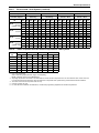
Table 7
Electrical data—60 Hz Systems (continued)
Chilled Water Models - 60Hz
Reheat Options
Humidifier Options
Models / Motor
HP
Volts
FLA
CW106
20.0 HP WSA
(Upflow only) MFCB
FLA
CW114
10.0 HP WSA
MFCB
FLA
CW114
WSA
15.0 HP
MFCB
FLA
CW114
20.0 HP WSA
(Upflow only) MFCB
Table 8
Electric
None
Electric
Electric
Infrared or Steam
Generating
Infrared or Steam
Generating
Steam or None
Steam or None
208
230
460
575
230
460
575
208
230
460
575
208
230
460
575
165.1
206.4
225
136.5
170.6
175
151.9
189.9
200
165.1
206.4
225
154.8
193.5
200
128.8
161.0
150
142.8
178.5
175
154.8
193.5
200
77.7
97.1
110
64.7
80.9
80
71.7
89.6
90
77.7
97.1
110
63.7 86.0 76.2
79.6 107.5 95.3
90
150 125
52.7 57.4 50.2
65.9 71.8 62.8
60
90
80
58.7 72.8 64.2
73.4 91.0 80.3
70
125 110
63.7 86.0 76.2
79.6 107.5 95.3
90
150 125
208
38.6
48.3
70
25.6
32.0
40
32.6
40.8
50
38.6
48.3
70
33.6
42.0
60
22.6
28.3
35
28.6
35.8
45
33.6
42.0
60
138.5
173.1
200
109.9
137.4
125
125.3
156.6
175
138.5
173.1
200
132.6
165.8
200
106.6
133.3
125
120.6
150.8
150
132.6
165.8
200
66.1
82.6
90
53.1
66.4
70
60.1
75.1
80
66.1
82.6
90
52.1
65.1
70
41.1
51.4
50
47.1
58.9
60
52.1
65.1
70
59.4
74.3
125
30.8
38.5
60
46.2
57.8
100
59.4
74.3
125
54.0
67.5
110
28.0
35.0
60
42.0
52.5
90
54.0
67.5
110
27.0
33.8
60
14.0
17.5
30
21.0
26.3
45
27.0
33.8
60
22.0
27.5
45
11.0
13.8
20
17.0
21.3
35
22.0
27.5
45
Indoor evaporator fan motor electrical requirements—60Hz systems
208
230
460
575
Hp
FLA
LRA
FLA
LRA
FLA
LRA
FLA
LRA
2.0 HP
3.0 HP
5.0 HP
7.5 HP
10.0 HP
15.0 HP
20.0 HP
7.5
10.6
16.7
24.2
30.8
46.2
59.4
46.9
66.0
105.0
152.0
193.0
290.0
321.0
6.8
9.6
15.2
22.0
28.0
42.0
54.0
40.8
58.0
91.0
132.0
168.0
252.0
290.0
3.4
4.8
7.6
11.0
14.0
21.0
72.0
20.4
26.8
45.6
66.0
84.0
126.0
145.0
2.7
3.9
6.1
9.0
11.0
17.0
22.0
16.2
23.4
36.6
54.0
66.0
102.0
116.0
1. Refer to General Data Section for standard fan motor size on units.
2. FLA = FulL Load Amps
WSA = Wire Sizing Amps (Minimum supply circuit ampacity)
MFCB = Maximum Fuse or Circuit Breaker Size
3. Amperage requirements are based on the rated max FLA current of each component in the unit. The rated max FLA current of the unit
is not the sum total of all components, but is the total of the components which operate during maximum electrical load conditions.
4. The values in the chart are for power of the unit only.
5. Units are 3 phase, 60 cycle.
6. For units with other variations not listed above, consult factory engineering department for electrical requirements.
15
Guide Specifications
GUIDE SPECIFICATIONS
1.0
GENERAL
1.1
Summary
These specifications describe requirements for a precision environmental control system. The system
shall be designed to maintain temperature conditions in the rooms containing electronic equipment.
The manufacturer shall design and furnish all equipment to be fully compatible with heat dissipation
requirements of the room.
1.2
Design Requirements
The precision environmental control system shall be a Liebert self-contained factory assembled unit
with (upflow) (down-flow) air delivery. The system shall have a total cooling capacity of ____ BTU/
HR, (kW) with a sensible cooling capacity of ____ BTU/ HR (kW) based on an entering air temperature
of ____ °F (°C) dry bulb and ____ °F (°C) wet bulb. The unit is to be supplied with ____ volt ____ ph
____ Hz electrical service.
1.3
Submittals
Submittals shall be provided with the proposal and shall include: Single-Line Diagrams; Dimensional, Electrical, and Capacity Data; Piping and Electrical Connection Drawings.
2.0
PRODUCT
2.1
Cabinet and Frame Construction
The frame shall be constructed of heliarc welded tubular steel. It shall be painted using the autophoretic coating process for maximum corrosion protection. The exterior panels shall be insulated
with a minimum 1 in. (25.4mm), 1.5 lb. (0.68 kg) density fiber insulation. The main front panel shall
have captive 1/4 turn fasteners. The main unit color shall be _________. The accent color shall be
_________. The exterior panels shall be powder coated.
2.2
Filter Chamber
The filter chambers shall be an integral part of the system, located within the cabinet serviceable
from either end of the unit. The filters shall be rated not less than ____% efficiency (based on
ASHRAE 52.1).
For models CW106 and CW114, the filters shall be serviceable from the front of the unit.
2.3
Fan Section
The fan shall be the centrifugal type, double width double inlet, and shall be factory-balanced as a
completed assembly. The shaft shall be heavy duty steel with self-aligning ball bearings with a minimum life span of 100,000 hours. The fan motor shall be ____ hp at 1750 RPM at 60 Hz (1450 RPM at
50 Hz) and mounted on an adjustable slide base. The drive package shall be two-belt, variable speed,
sized for 200% of the fan motor horsepower. The fans shall be located to draw air over the A-frame coil
to ensure even air distribution and maximum coil performance.
2.3
Electronically Commutated (EC) Fan
2.4
The fan shall be the plug/plenum type, single inlet and shall be dynamically balanced. The fan motor
shall be 4.2 hp, 1520 rpm maximum operating speed. The drive package shall be direct drive Electronically Commutated, variable speed. The fans shall be located to draw air over the A-frame coil to
ensure even air distribution and maximum coil performance.
Liebert iCOM™ Microprocessor Control With Small Graphic Display
The Liebert iCOM unit control shall be factory-set for Intelligent Control which uses “fuzzy logic” and
“expert systems” methods. Proportional and Tunable PID shall also be user selectable options. Internal unit component control shall include the following:
16
Guide Specifications
System Auto Restart - The auto restart feature will automatically restart the system after a power
failure. Time delay is programmable.
Sequential Load Activation - On initial startup or restart after power failure, each operational
load is sequenced with a minimum of one second delay to minimize total inrush current.
Hot Water Flush Cycles - Hot water reheat coils and Econ-O-Coils are periodically flushed to prevent a buildup of contaminants.
Predictive Humidity Control - calculates the moisture content in the room and prevents unnecessary humidification and dehumidification cycles by responding to changes in dew point temperature.
The Liebert iCOM control shall be compatible with Liebert remote monitoring and control devices.
Options are available for BMS interface via MODbus, Jbus, BACNet, Profibus and SNMP.
The Liebert iCOM control processor shall be microprocessor based with a 128x64 dot matrix graphic
front monitor display and control keys for user inputs mounted in an ergonomic, aesthetically pleasing housing. The display & housing shall be viewable while the unit panels are open or closed. The
controls shall be menu driven. The display shall be organized into three main sections: User Menus,
Service Menus and Advanced Menus. The system shall display user menus for: active alarms, event
log, graphic data, unit view/status overview (including the monitoring of room conditions, operational
status in % of each function, date and time), total run hours, various sensors, display setup and service contacts. A password shall be required to make system changes within the service menus. Service
menus shall include: setpoints, standby settings (lead/lag), timers/sleep mode, alarm setup, sensor
calibration, maintenance/wellness settings, options setup, system/network setup, auxiliary boards
and diagnostics/service mode. A password shall be required to access the advanced menus which
include the factory settings and password menus.
The User Menus Shall be Defined as Follows
Active Alarms: Unit memory shall hold the 200 most recent alarms with time and date stamp for
each alarm.
Event Log: Unit memory shall hold the 400 most recent events with ID number, time and date
stamp for each event.
Graphic Data View: Eight graphic records shall be available: return air temperature, return air
humidity, supply air temperature, outdoor temperature and four custom graphs.
Unit View: Status Overview: Simple or Graphical “Unit View” summary displays shall include temperature and humidity values, active functions (and percent of operation) and any alarms of the host
unit.
Total Run Hours: Menu shall display accumulative component operating hours for major components including fan motor, humidifier and reheat.
Various Sensors: Menu shall allow setup and display of optional custom sensors. The control shall
include four customer accessible analog inputs for sensors provided by others. The analog inputs shall
accept a 4 to 20mA signal. The user shall be able to change the input to 0 to 5VDC or 0 to 10VDC if
desired. The gains for each analog input shall be programmable from the front display. The analog
inputs shall be able to be monitored from the front display.
Display Setup: Customer shall pre-select the desired grouping of display languages at the time of
the order from the following choices:
•
•
•
•
Group 1: English, French, Italian, Spanish, German
Group 2: English, Russian, Greek
Group 3: English, Japanese, Chinese, Arabic
Service Contacts: Menu shall allow display of local service contact name and phone number.
17
Guide Specifications
The Service Menus Shall be Defined as Follows
Setpoints: Menu shall allow setpoints within the following ranges:
•
•
•
•
•
•
•
•
Temperature Setpoint 65-85ºF (18-29ºC)*
Temperature Sensitivity +1-10ºF (0.6-5.6ºC)
Humidity Setpoint 20-80% RH*
Humidity Sensitivity 1-30% RH
High Temperature Alarm 35-90ºF (2-32ºC)
Low Temperature Alarm 35-90ºF (2-32ºC)
High Humidity Alarm 15-85% RH
Low Humidity Alarm 15-85% RH
* The microprocessor may be set within these ranges, however, the unit may not be able to control to
extreme combinations of temperature and humidity.
Standby Settings/Lead-Lag: Menu shall allow planned rotation or emergency rotation of operating
and standby units.
Timers/Sleep Mode: Menu shall allow various customer settings for turning on/off unit.
Alarm Setup: Menu shall allow customer settings for alarm notification (audible/local/remote). The
following alarms shall be available:
•
•
•
•
•
•
•
•
•
High Temperature
Low Temperature
High Humidity
Low Humidity
Main Fan Overload (Optional)
Humidifier Problem
Change Filter
Fan Failure
Unit Off
Audible Alarm: The audible alarm shall annunciate any alarm that is enabled by the operator.
Common Alarm: A programmable common alarm shall be provided to interface user selected alarms
with a remote alarm device.
Remote Monitoring: All alarms shall be communicated to the Liebert monitoring system with the
following information: Date and time of occurrence, unit number and present temperature and
humidity.
Sensor Calibration: Menu shall allow unit sensors to be calibrated with external sensors.
Maintenance/Wellness Settings: Menu shall allow reporting of potential component problems
before they occur.
Options Setup: Menu shall provide operation settings for the installed components.
System/Network Setup: Menu shall allow Unit-to-Unit (U2U) communication and setup for teamwork modes of operation (up to 32 units).
Teamwork Modes of Operation: Saves energy by preventing operation of units in opposite modes
multiple units.
Auxiliary Boards: Menu shall allow setup of optional expansion boards.
Diagnostics/Service Mode: The Liebert iCOM control shall be provided with self-diagnostics to aid
in troubleshooting. The microcontroller board shall be diagnosed and reported as pass/not pass. Control inputs shall be indicated as on or off at the front display. Control outputs shall be able to be
turned on or off from the front display without using jumpers or a service terminal. Each control output shall be indicated by an LED on a circuit board.
18
Guide Specifications
Advanced Menus
Factory Settings: Configuration settings shall be factory-set based on the pre-defined component
operation.
Change Passwords: Menu shall allow new passwords to be set or changed.
2.4.1
Liebert iCOM Microprocessor Control With Large Graphic Display (Optional)
The Liebert iCOM unit control with large graphic display shall include all of the features as the Liebert iCOM with small graphic display, except that it includes a larger graphical display and shall
include the additional features of:
“System View”, Spare Parts List, Unit Diary.
The Liebert iCOM control processor shall be microprocessor based with a 320x240 dot matrix graphic
front monitor display panel and control keys for user inputs mounted in an ergonomic, aesthetically
pleasing housing.
System View - Status Overview: “System View” shall display a summary of operation for the total
number of operating units within a Unit-to-Unit (U2U) configuration.
Spare Parts List: Menu shall include a list of critical spare parts, their quantity and part numbers.
Unit Diary: Menu shall include a free field area within the unit memory where unit history may be
stored for reference.
2.5
Liebert iCOM Wall-Mount Large Graphic Display (Optional)
The Liebert iCOM Large Graphic Display Kit shall include an ergonomic, aesthetically pleasing housing, a 320x240 dot matrix graphic display and a 120V power supply. The Wall-Mount Large Graphic
Display shall be used to allow remote location of a “System View” display and all features of the Large
Graphic User, Service and Advanced menus for use with Liebert iCOM controlled products connected
for Unit-to-Unit (U2U) communications.
2.5.1
Control
The control system shall allow programming of the following room conditions:
• Temperature Setpoint: 65-85°F (18-29°C)
• Temperature Sensitivity: ±1° to 9.9°F (0.6 to 5.6°C) in 0.1°F (0.1°C) increments
All setpoints shall be adjustable from the individual unit front monitor panel. Temperature and
humidity sensors shall be capable of being calibrated using the front monitor panel controls to coordinate with other temperature and humidity sensors in the room.
In addition, the system shall provide the following internal controls:
2.5.1.1
System Auto-Restart
For startup after power failure, the system shall provide automatic restart with a programmable (up
to 9.9 minutes in 6-second increments) time delay. Programming can be performed either at the unit
or from the central site monitoring system.
2.5.1.2
Sequential Load Activation
During startup or after a power failure, the Liebert iCOM control shall sequence operational load
activation to minimize inrush current. Systems allowing multiple loads to start simultaneously are
unacceptable.
2.5.1.3
Front Monitor Display Panel
The Liebert iCOM control shall provide a front monitor LCD, backlit display panel with 4 rows of 20
characters with adjustable contrast. This display (along with nine front-mounted control keys) shall
be the only operator interface required to obtain all available system information such as room conditions, operational status, alarms, control and alarm setpoints and all user selections including alarm
delays, sensor calibration, DIP switch selections and diagnostics. All indicators shall be in language
form. No symbols or codes shall be acceptable.
19
Guide Specifications
2.5.1.4
Alarms
The Liebert iCOM control shall activate an audible and visual alarm in event of any of the following
conditions:
•
•
•
•
•
•
•
•
•
High Temperature
Low Temperature
High Humidity
Low Humidity
Main Fan Overload (opt)
Change Filters
Loss of Air Flow
Loss of Power
Custom Alarm (#1 to #4)
Custom alarms are four customer accessible alarm inputs to be indicated on the front panel. Custom
alarms can be identified with prepared (programmed) labels for the following frequently used inputs:
•
•
•
•
Leak Under Floor
Smoke Detected
Loss of Water Flow
Standby Unit On
User customized text can be entered for two of the four custom alarms.
Each alarm (unit and custom) can be separately enabled or disabled, selected to activate the common
alarm, and programmed for a time delay of 0 to 255 seconds.
2.5.1.5
Audible Alarm
The audible alarm shall annunciate any alarm that is enabled by the operator.
2.5.1.6
Common Alarm
A programmable common alarm shall be provided to interface user selected alarms with a remote
alarm device.
2.5.1.7
Remote Monitoring
All alarms shall be communicated to the Liebert site monitoring system with the following information: date and time of occurrence, unit number and current temperature and humidity.
2.5.1.8
Diagnostics
The control system and electronic circuitry shall be provided with self-diagnostics to aid in troubleshooting. The microcontroller board shall be diagnosed and reported as pass/not pass. Control inputs
shall be indicated as on or off at the front monitor panel. Control outputs shall be able to be turned On
or Off from the front monitor panel without using jumpers or a service terminal.
2.5.1.9
Data Collection
The control system shall maintain accumulative operating hours of compressors, fan motor and EconO-Coil. The 10 most recent alarms shall be retained.
2.5.1.10 Communication
The Liebert iCOM control shall be compatible with Liebert remote monitoring and control devices.
2.6
Chilled Water Control Valve
The water circuit shall include a 3-way (2-way) modulating valve. The Liebert iCOM positions the
valve in response to room conditions. Cooling capacity will be controlled by bypassing chilled water
around the coil.
20
Guide Specifications
2.7
High Pressure Chilled Water Control Valve—Optional
The chilled water circuit shall include a 3-way (2-way) high pressure modulating valve. The valve
shall be designed for up to 400 PSI (2758 kPa) water pressure.
2.8
A-Frame Chilled Water Coil
The cooling coil shall be of A-frame design with a minimum of ____ sq. ft. (sq.m.) face area, ____ rows
deep.
The coil shall be controlled by a 3-way modulating control valve. It shall be constructed of copper
tubes and aluminum fins and have a maximum face velocity of ____ ft. per minute (m/s) at ____ CFM
(CMH).
The water circuit shall be designed to distribute water into the entire coil face area. The coil shall be
supplied with ____ °F (°C) entering water temperature, with a ____ °F (°C) temperature rise. The coil
shall require ____ GPM (l/s) of chilled water and the pressure drop shall not exceed ____ PSI (kPa).
The entire coil assembly shall be mounted in a stainless steel condensate drain pan.
For models CW106 and CW114, the end sheets shall be aluminum, and the coil can be removed from
the front or either side of the unit.
2.9
Flow Switch—Optional
The flow switch shall activate the alarm system should the chilled water supply be interrupted. The
switch shall be factory mounted and wired.
2.10
Variable Speed Drive—Optional
A variable speed drive (VSD) is available for models CW106 and CW114 to reduce energy consumption. The fan motor speed shall be varied from 100% to 60% of rated speed in response to room conditions. This shall be controlled automatically by the Liebert iCOM control. The variable speed drive
option shall be available with an infrared humidifier.
2.11
Optional Components
The computer room environmental control system shall be equipped with the following optional components.
2.11.1 Disconnect Switch—Non-Locking Type
The manual disconnect switch shall be mounted in the high voltage section of the electrical panel. The
switch shall be accessible with the door closed.
2.11.2 Disconnect Switch—Locking Type
The manual disconnect switch shall be mounted in the high voltage section of the electrical panel. The
switch shall be accessible from the outside of the unit with the door closed, and prevent access to the
high voltage electrical components until switched to the “OFF” position.
2.11.3 High Temp Stat
The high temp stat shall immediately shut down the environmental control system when activated.
The high temp stat shall be mounted in the electrical panel with the sensing element in the return
air.
2.11.4 Condensate Pump, Dual Float
The condensate pump shall have a minimum capacity of 100 GPH at 20 ft. (378 l/hr at 6m) head.
(Consult factory for 200V or 230V, 50 Hz applications.) It shall be complete with integral float switch,
pump and motor assembly, and reservoir. Secondary float shall shut down unit if tripped.
2.11.5 Liebert Liqui-tect™ Sensors (Max. of Two Per Unit)
Provide ____ (quantity) solid state water sensors under the raised floor.
21
Guide Specifications
2.11.6 Floor Stand
The floor stand shall be constructed of a heliarc-welded, tubular steel frame. The floor stand shall
have adjustable legs with vibration isolation pads. The floor stand shall be ____ inches high.
2.11.6.1 Floor Stand Turning Vane
A factory-supplied, field-mounted turning vane shall be provided.
2.11.6.2 Smoke Sensor
The smoke sensor shall immediately shut down the environmental control system and activate the
alarm system when activated. The smoke sensor shall be mounted in the electrical panel with the
sensing element in the return air compartment.
2.11.6.3 Liebert SiteScan® Site Monitoring System
Provide a Liebert SiteScan monitor system with the Liebert CW. The Liebert SiteScan shall have the
capability to monitor and change (at the user direction) the temperature setpoints and sensitivities of
each unit. The printer shall provide the user with chronological alarm information. It shall also be
capable of being programmed to print out environmental conditions or operating modes at each unit.
3.0
EXECUTION
3.1
Installation of Precision Cooling Units
3.1.1
General
Install precision cooling units in accordance with manufacturer’s installation instructions. Install
units plumb and level, firmly anchored in locations indicated, and maintain manufacturer’s recommended clearances.
3.1.2
Electrical Wiring
Install and connect electrical devices furnished by manufacturer but not specified to be factory
mounted. Furnish copy of manufacturer’s electrical connection diagram submittal to electrical contractor.
3.1.3
Piping Connections
Install and connect devices furnished by manufacturer but not specified to be factory-mounted. Furnish copy of manufacturer’s piping connection diagram submittal to piping contractor.
3.2
Field Quality Control
Startup mainframe coolant units in accordance with manufacturer’s startup instructions. Test controls and demonstrate compliance with requirements.
22
Ensuring The High Availability
Of Mission-Critical Data And Applications.
Emerson Network Power, the global leader in enabling business-critical
continuity, ensures network resiliency and adaptability through
a family of technologies—including Liebert power and cooling
technologies—that protect and support business-critical systems.
Liebert solutions employ an adaptive architecture that responds
to changes in criticality, density and capacity. Enterprises benefit
from greater IT system availability, operational flexibility and
reduced capital equipment and operating costs.
Technical Support / Service
Web Site
www.liebert.com
Monitoring
800-222-5877
[email protected]
Outside the US: 614-841-6755
Single-Phase UPS
800-222-5877
[email protected]
Outside the US: 614-841-6755
Three-Phase UPS
800-543-2378
[email protected]
Environmental Systems
800-543-2778
Outside the United States
614-888-0246
Locations
United States
1050 Dearborn Drive
P.O. Box 29186
Columbus, OH 43229
Europe
Via Leonardo Da Vinci 8
Zona Industriale Tognana
35028 Piove Di Sacco (PD) Italy
+39 049 9719 111
Fax: +39 049 5841 257
Asia
7/F, Dah Sing Financial Centre
108 Gloucester Road, Wanchai
Hong Kong
852 2572220
Fax: 852 28029250
While every precaution has been taken to ensure the accuracy
and completeness of this literature, Liebert Corporation assumes no
responsibility and disclaims all liability for damages resulting from use of
this information or for any errors or omissions.
© 2008 Liebert Corporation
All rights reserved throughout the world. Specifications subject to change
without notice.
® Liebert is a registered trademark of Liebert Corporation.
All names referred to are trademarks
or registered trademarks of their respective owners.
SL-18056_REV0_11-08
Emerson Network Power.
The global leader in enabling Business-Critical Continuity.
AC Power
Embedded Computing
Embedded Power
Connectivity
DC Power
Monitoring
Outside Plant
Power Switching & Controls
Precision Cooling
EmersonNetworkPower.com
Racks & Integrated Cabinets
Services
Surge Protection
Business-Critical Continuity, Emerson Network Power and the Emerson Network Power logo are trademarks and service marks of Emerson Electric Co.
©2008 Emerson Electric Co.