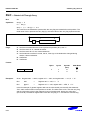
1
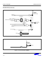
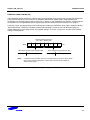
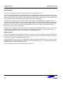
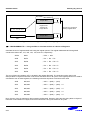
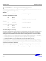
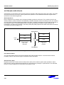
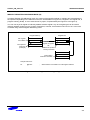
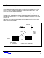
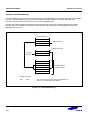
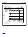
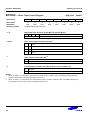
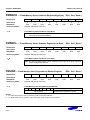
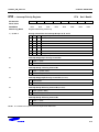
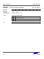
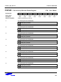
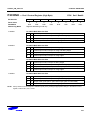
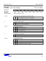
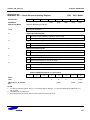
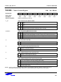
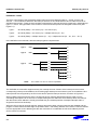
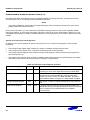
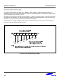
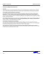
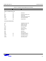
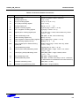
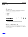
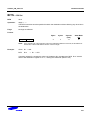
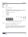
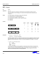
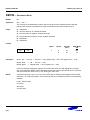
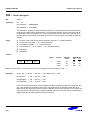
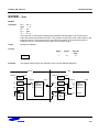
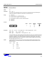
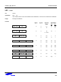
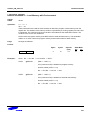
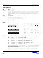
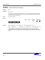
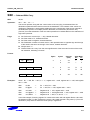
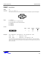
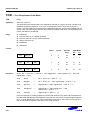
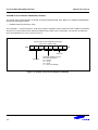
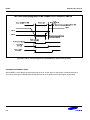
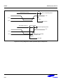
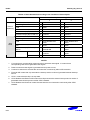
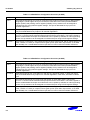
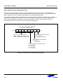
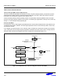
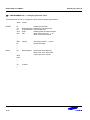
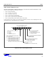
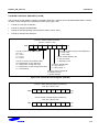
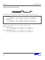
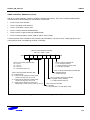
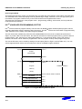
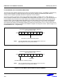
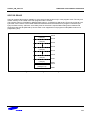
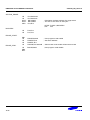
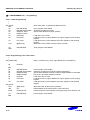
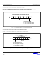
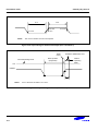
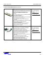
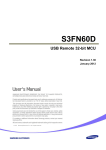
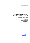
INTERRUPT STRUCTURE
S3F80P9_UM_ REV1.00
INTERRUPT MASK REGISTER (IMR)
The interrupt mask register, IMR (DDH, Set 1, Bank0) is used to enable or disable interrupt processing for
individual interrupt levels. After a reset, all IMR bit values are undetermined and must therefore be written to their
required settings by the initialization routine.
Each IMR bit corresponds to a specific interrupt level: bit 1 to IRQ1, bit 2 to IRQ2, and so on. When the IMR bit of
an interrupt level is cleared to "0", interrupt processing for that level is disabled (masked). When you set a level's
IMR bit to "1", interrupt processing for the level is enabled (not masked).
The IMR register is mapped to register location DDH in set 1and Bank0. Bit values can be read and written by
instructions using the register addressing mode.
Figure 5-6. Interrupt Mask Register (IMR)
5-10