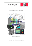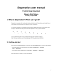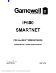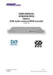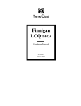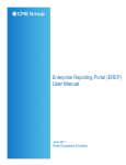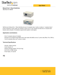
1
MICRF50x
User Manual for RF TestBench
SW V. 0.5
Doc. V. 1
Micrel Norway AS
Strandveien 13 * 1366 LYSAKER * Norway
Tel: +47 67 83 08 00 * Fax: +47 67 83 08 10
RF TestBench User Guide, SW v05, doc v1
Table of contents:
1.
2.
3.
Introduction................................................................................................................. 2
Install RF TestBench................................................................................................... 4
Menu items and dialog boxes ..................................................................................... 4
3.1.
Æ Setup .............................................................................................................. 5
3.2.
Æ Setup ÆSelect MICRF505 or MICRF506 chip…......................................... 5
3.3. Æ Setup ÆCommunication port … ................................................................... 5
3.4. ÆRF TestBench.................................................................................................. 6
3.5.
ÆRF TestBench ÆOverview …........................................................................ 6
3.6.
ÆRF TestBench ÆQuick Setup…..................................................................... 7
3.7.
ÆRF TestBench ÆComplete Setup … ............................................................ 10
3.8.
ÆRF TestBench ÆDevelopment Board Commands … .................................. 12
3.9.
ÆRF TestBench ÆFrequency Error Estimator …........................................... 13
3.10.
ÆCalculate A,N,M … .................................................................................. 14
3.11.
ÆCalculate A,N,MÆFind 1…n frequencies, using modulator… ............... 14
3.12.
ÆCalculate A,N,MÆFind 1…n frequencies, using two sets of dividers…. 14
3.13.
ÆLoop Filter ................................................................................................ 15
3.14.
ÆLoop FilterÆFind 2nd Order …............................................................... 15
3.15.
ÆDeviation................................................................................................... 15
3.16.
ÆDeviationÆDeviation Select Help …....................................................... 15
Micrel Norway AS
1
RF TestBench User Guide, SW v05, doc v1
1. Introduction
This document, “MICRF50x User Manual for RF TestBench” describes how to set up
and use RF TestBench. For details on the MICRF505/MICRF506 transceiver or the
MICRF505/MICRF506 development system: Please refer to the appropriate data sheet.
For the latest updates, visit the homepage of Micrel.
The RF TestBench should be self-explaining. Use this document as a reference; it is not
necessary to read it through before starting to use RF TestBench.
Also note: Any calculated value in this program should be considered a suggestion. When
transferred to a specific application, always test the RF performance.
Outline of this document:
Following this introduction, a Setup chapter is given. Then the different menu items and
dialog boxes are described. “MICRF50x” is a short-term for “MICRF505/MICRF506”
Purpose of the RF TestBench:
RF TestBench can be used with or without a “development board”.
Users of MICRF50x radio transceiver can use the RF TestBench to calculate fields in the
control word to enter into the RF chip.
Typical examples are:
• Get the complete 22-byte long control word to enter into the RF chip
• Get the “M”, “A”, “N” dividers for a specific frequency or a set of frequencies
• Get the “Mod_A” “Mod_I”, “Mod_clkS” and “RefClk_K” values for a specific
deviation
• Get the resulting deviation, bit rate etc for a specific set of parameters
• Get external components values for a loop filter
Main features:
• Quick Setup. Enter parameters like xtal frequency, wanted bit rate, RF frequency. Or
select the “default” settings. Then see what the fields in the control word should be.
Transfer control word to development board (where it is stored in EEPROM)
•
Complete Setup. Enter fields in the control word or select the “default” settings.
Then see the resulting bit rate, deviation etc. Transfer control word to development
board (where it is stored in EEPROM)
•
Commands to development board. The set of commands to the board includes start
to transmit 1010…, get firmware version, restart micro controller, reset EEPROM and
read EEPROM
Micrel Norway AS
2
RF TestBench User Guide, SW v05, doc v1
•
Frequency Error Estimator (FEE): Read out the FEE for different XCO-tune
values, or find the best XCO tune value automatically
•
Calculate A,N,M. Find 1-64 frequencies or set of frequencies
•
Loop filter. Find values of external components for the loop filter
•
Deviation help. Get suggestions for minimum deviation and filter settings, based on
RF frequency, xtal tolerance etc
Micrel Norway AS
3
RF TestBench User Guide, SW v05, doc v1
2. Install RF TestBench
The installation of RF TestBench is straightforward:
•
Copy the included files into a separate directory. If no files have .exe / .bat
extensions, please rename files in the following way: The 2 files having an “eee”
extension should be renamed to have an “exe” extension, and the file having a
“bbb” extension should be renamed to have a “bat” extension
•
By double-clicking the PCxx.bat file (xx=software version number):
o First, the “loadbwcc” program is started. This will initiate the PC for the
controls used in the program
o Then “PCxx” is started (xx=software version number)
•
Start the program by double-clicking “PCxx.bat” (xx = sw version number)
•
When the program starts, a welcome-message is displayed. Please read it. You
can select to close the welcome-message by pressing the “OK” button, or you can
select to keep the window
•
In addition, a window called “Overview” is opened when the program starts. In
this window, the complete 22-byte long control word to enter into the RF chip
will be displayed. At start-up, the window will be empty
3. Menu items and dialog boxes
In the following, the menu items and dialog boxes will be described. A menu item is
always preceded with “Æ”. First, the menu item from the main menu is described. Then
the sub-items of the main menu item are described (and so on).
Micrel Norway AS
4
RF TestBench User Guide, SW v05, doc v1
3.1. Æ Setup
This is where the MICRF505 or MICRF506 chip is selected. In addition, this is where the
communication port is selected (relevant only if you are using a “development board”).
3.2. Æ Setup ÆSelect MICRF505 or MICRF506 chip…
The “Select Chip” dialog box (window) appears.
Push Buttons:
• MICRF505
o Press this button to select the MICRF505. Then the window is
automatically closed
• MICRF506
o Press this button to select the MICRF506. Then the window is
automatically closed
• OK
o Press this button to exit the window. If you open the window, the
previously selected (if any) RF chip is displayed
Output fields:
• Present Selection
o If no RF chip is selected, this field is blank. If a RF chip is selected,
“MICRF505” or “MICRF506” will be displayed
3.3. Æ Setup ÆCommunication port …
The “Select COM port” dialog box (window) appears.
Push Buttons:
• Select COM1
o Press this button if you want to use serial port “COM 1”. If not possible to
open (some other program may be using it), you will get a message. If the
port is successfully opened, the window is automatically closed
• Select COM2
o Press this button if you want to use serial port “COM 2”. If not possible to
open (some other program may be using it), you will get a message. If the
port is successfully opened, the window is automatically closed
• Close COM port
o Press this button if you want to close the presently selected serial port, but
still run the program. This is useful if you need to use the COM port in
another program. The window is automatically closed
• Return
o Press this button to close the window without opening or closing a port
Micrel Norway AS
5
RF TestBench User Guide, SW v05, doc v1
3.4. ÆRF TestBench
This is where you can construct/change a control word for MICRF50x. You can give
commands to the development board here.
3.5. ÆRF TestBench ÆOverview …
The “RF TestBench: Overview” window pops up.
Output fields:
• Address (hex)
o The address of a byte in the MICRF50x control word. The “Address”
range is from 0x00 to 0x15 (a total of 22 bytes - all the editable locations
in the RF chip)
• Address (dec)
o The address of a byte in the MICRF50x control word. The “Address”
range is from 0 to 21 (a total of 22 bytes - all the editable locations in the
RF chip)
• Value (hex)
o The value of the byte with address 0, address 1 etc is shown as a hex
number
• Changed from (hex)
o If, after calculations in Quick/Complete, the content is changed, the
previous value will be shown here
Micrel Norway AS
6
RF TestBench User Guide, SW v05, doc v1
3.6. ÆRF TestBench ÆQuick Setup…
The “RF TestBench: Quick Setup” window pops up.
Input fields:
• Xtal Frequency
o Enter the frequency (in MHz) of the xtal connected to the RF part
• Wanted Bit rate
o Enter the wanted “on-the-air” bit rate. This is also referred to as “number
of “signal elements/second”
• Wanted RF Frequency
o Enter the RF center frequency (in MHz). This will be the frequency used
in receive mode
• Wanted Single-Sided Dev.
o Enter the single-sided deviation (in kHz). The frequency for transmitting a
“0” will be the “Wanted RF Frequency” – “Wanted Single-Sided Dev”,
and the frequency for “1” will be “Wanted RF Frequency” + “Wanted
Single-Sided Dev”
• Wanted Comp. Freq.
o Enter the wanted comparison frequency (in kHz) here
• Wanted SC Cutoff
o Enter the wanted cut-off frequency for the switch-cap filter here
Tolerance:
When calculating the control word, it may be that the “Wanted” values are not
completely found. The tolerances used in the calculations are:
•
•
•
•
•
Wanted Bit rate: No tolerance, the nearest value is used
Wanted RF Frequency: +- 200kHz
Wanted Single-Sided Dev. : +-10%
Wanted Comp. Freq. : +- 25%
Wanted SC Cutoff: No tolerance is used, the lowest value >= the wanted value is
used (or the maximum achievable value)
Output Fields:
• Achieved Bit rate
o Note that achieved bit rate may differ from the wanted bit rate. If a
specific bit rate is wanted but not achieved: Consider another xtal
frequency
• Achieved RF Freq.
o This will be the achieved frequency used in receive mode
• Achieved Single_Sided Dev.
Micrel Norway AS
7
RF TestBench User Guide, SW v05, doc v1
•
•
•
o If VCO modulation is selected, one number is displayed here. This is the
achieved single sided deviation
o If Internal modulation (switching between two sets of A,N,M dividers) is
selected, two numbers are displayed. These are the achieved deviation for
tx “0” and tx “1”, resp.
Achieved Comp. Freq
o If VCO modulation is selected, one number is displayed here. This is the
achieved comp frequency
o If Internal modulation (switching between two sets of A,N,M dividers) is
selected, three numbers are displayed. These are the achieved comparison
frequency for rx, tx “0” and tx “1”, resp.
Achieved SC Cutoff
o Achieved switchcap cut off frequency
Status
o Messages related to the transfer of commands are displayed here. After
pressing Transfer, “Waiting…” will be displayed. If no response from
board, “Waiting…” will continue to be displayed. If response from board
is received, “Success” or “Error” will be displayed. If Error: Please test
communication cable, power, DIP switch setting and jumpers.
Groups of “radio buttons”:
The groups of “radio-buttons” are self-explaining. Within a group, only one item can be
selected.
• Mode of Operation
• Prefilter Cutoff
• Modulation Type
• Output Power Level
Push Buttons:
• Calc!
o Press this button to update the output fields and the “Overview” and
“Complete Setup” window (if open). Calculations are based on the input
fields from the “Quick Setup” window
• See Details
o Press this button to open the “Complete Setup” window
• Default
o All input fields are reset to default settings
• Transfer!
o Transfer control word to the development board. The user-entered control
word will be stored in the EEPROM of the micro controller
• Cancel
o Close window
• Store
Micrel Norway AS
8
RF TestBench User Guide, SW v05, doc v1
•
o The control word is stored in a file, using the following naming
convention: rftb_xxx.txt, where xxx=a number, ranging from 000 to 999.
The first, not-excisting number is used, and a message-window pops up.
Import
o A window pops up, enter the name of the file to import: rftb_xxx.txt. If no
file name is entered, or the entered file cannot be opened, a message
window will pop up.
Micrel Norway AS
9
RF TestBench User Guide, SW v05, doc v1
3.7. ÆRF TestBench ÆComplete Setup …
The “RF TestBench: Complete Setup” window pops up.
Input fields:
• Xtal Frequency
o Enter the frequency (in MHz) of the xtal connected to the RF part.
• Fields related to the control word:
o These are self-explaining (refer to MICRF50x data sheet)
• General Input field:
o It is possible to change all bits, including “fixed” bits, by entering the
address and value directly. Unused bits are not editable.
Output Fields:
• Following some of the inputs, an output-field is included. The effect or result of
the selection is shown (updated after “Calc!” is pressed)
• Status
o Messages related to the transfer of commands are displayed here. After
pressing Transfer, “Waiting…” will be displayed. If no response from
board, “Waiting…” will continue to be displayed. If response from board
is received, “Success” or “Error” will be displayed. If Error: Please test
communication cable, power, DIP switch setting and jumpers.
Push Buttons:
• Calc!
o Press this button to update the output fields and the “Overview” and the
“Quick Setup” window (if open). Calculations are based on the input
fields from the “Complete Setup” window (note that both “wanted” and
“achieved” fields in the Quick Setup window will be changed)
• Default
o All input fields are reset to default settings
• Transfer!
o Transfer control word to the development board. The user-entered control
word will be stored in the EEPROM of the micro controller
• Cancel
o Close window
• Store
o The control word is stored in a file, using the following naming
convention: rftb_xxx.txt, where xxx=a number, ranging from 000 to 999.
The first, not-existing number is used, and a message-window pops up.
• Import
Micrel Norway AS
10
RF TestBench User Guide, SW v05, doc v1
•
o A window pops up, enter the name of the file to import: rftb_xxx.txt. If no
file name is entered, or the entered file cannot be opened, a message
window will pop up.
Update
o Press this button to write a specific value to a specific register. Note that
all the fields in the specified register will be updated!
Micrel Norway AS
11
RF TestBench User Guide, SW v05, doc v1
3.8. ÆRF TestBench ÆDevelopment Board Commands …
The “Commands to Development Board” window pops up.
Push Buttons:
• TX1010
o Start to transmit a 1010… pattern. Transmit-mode will be entered, overruling the entered control word.
• Get FW v.
o Get the firmware version of the program presently in the micro controller.
New features may be added to new versions of the firmware.
• Reset uC
o Restart micro controller
• Reset EEP
o Fill EEPROM with default settings of the control word
• Read EEP
o Read the presently stored EEPROM control word.
• Use FLASH
o Instruct the development board to use the control word stored in FLASH
program memory of the micro controller. This is identical to the “Default”
settings.
• Use EEP.
o Instruct the development board to use the control word stored in EEPROM
of the micro controller. The user-entered control word stored in EEPROM
is used in 2-way link test mode and simple byte transfer mode.
• Get Source
o Find out if the board will use the FLASH or the EEPROM memory (i.e.
the “default” and the “user-entered” control words, respectively)
• Cancel
o Close window
Output fields:
• FW version
o Present firmware version (micro controller program). FW version 99 is
used for test-programs.
• Control word read from EEPROM
o Presently EEPROM-stored control word
• Source is
o FLASH or EEPROM will be displayed
• Status
o Messages related to the transfer of commands are displayed here. After
pressing Transfer, “Waiting…” will be displayed. If no response from
board, “Waiting…” will continue to be displayed. If response from board
Micrel Norway AS
12
RF TestBench User Guide, SW v05, doc v1
is received, “Success” or “Error” will be displayed. If Error: Please test
communication cable, power, DIP switch setting and jumpers.
3.9. ÆRF TestBench ÆFrequency Error Estimator …
The “Frequency Error Estimator” window pops up.
This feature requires the use of a development board. NOTE: Not all development
board firmware versions will support this feature.
Read the FEE value by pressing the “Read!” button, or by stepping XCO-tune value
up/down.
Pressing the “Tune” button will start a process to get the best XCO tune value.
Before using this feature:
• Please read the MICRF50x user manual
• Set the development board in rx, on the wanted frequency and bit rate (Use
Quick/Complete dialog, press “Transfer”)
• Apply a tx-signal (use another development board or a signal generator)
Micrel Norway AS
13
RF TestBench User Guide, SW v05, doc v1
3.10.
ÆCalculate A,N,M …
This is an aid for determining frequency dividers. You can use Æ RF TestBench ÆQuick
Setup as well (to find 1 frequency /frequency set). Note that the tolerances in the Quick
Setup dialog are fixed, while they are adjustable here. This may give slightly different
results.
Experiment with tolerances etc to get the frequency set you want!
Frequencies are calculated based on the following priorities:
1. As close to the RF frequency as possible
2. As close to the comparison frequency as possible
3. If a RF frequency is not a 100% hit, it must improve the best RF frequency found
with > 1kHz, or else the one with the highest comparison frequency is used.
3.11.
ÆCalculate A,N,MÆFind 1…n frequencies, using modulator…
The “Calculate frequency dividers (A,N,M): Use modulator” window pops up.
1 or a number of frequencies (max 64) can be calculated.
Fill in wanted frequencies etc and press the “Calculate Dividers!” button. See the results.
It’s possible to store the results, the file will be named “extn_xxx.txt”, where xxx= a
number 000-999.
Note that new results are placed below the old ones in the window. A timestamp is
attached.
ÆCalculate A,N,MÆFind 1…n frequencies, using two sets of
3.12.
dividers…
The “Calculate frequency dividers (A,N,M): Use two sets of dividers” window pops up.
1 or a number of frequencies (max 64) can be calculated.
Fill in wanted frequencies etc and press the “Calculate Dividers!” button. See the results.
It’s possible to store the results, the file will be named “intn_xxx.txt”, where xxx= a
number 000-999.
Note that new results are placed below the old ones in the window. A timestamp is
attached.
Micrel Norway AS
14
RF TestBench User Guide, SW v05, doc v1
3.13.
ÆLoop Filter
This is help for determining component values of the external loop filter.
3.14.
ÆLoop FilterÆFind 2nd Order …
Enter values and calculate
3.15.
ÆDeviation
This is help for getting an idea of what the deviation and filter settings should be
3.16.
ÆDeviationÆDeviation Select Help …
Enter values and calculate.
These are the formulas used:
“minimum_deviation” = beta*bitrate/2 + 2*total_xtal_ppm*rf_frequency/1e6
“minimum _filter_cutoff" = minimum_deviation + 2*total_xtal_ppm*rf_frequency/1e6 +
bitrate/2
Note that the resulting “beta” will be higher than the input. The entered beta is considers
a “minimum beta”.
Micrel Norway AS
15