1
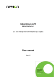
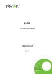
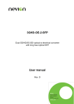
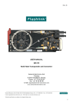
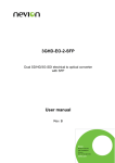
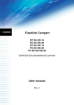
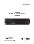
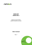
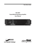
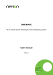
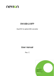
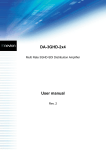
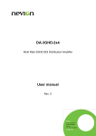
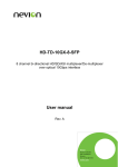
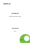
HDSDI-CHO-2x1 HD-SDI-CHO-2x1-PB HD-SDI Change-over 2x1 User manual Rev. G Nevion Nordre Kullerød 1 3241 Sandefjord Norway Tel: +47 33 48 99 99 nevion.com HDSDI-CHO-2x1 Rev. G Nevion Support Nevion Europe Nevion USA P.O. Box 1020 3204 Sandefjord, Norway Support phone 1: +47 33 48 99 97 Support phone 2: +47 90 60 99 99 1600 Emerson Avenue Oxnard, CA 93033, USA Toll free North America: (866) 515-0811 Outside North America: +1 (805) 247-8560 E-mail: [email protected] See http://www.nevion.com/support/ for service hours for customer support globally. Revision history Current revision of this document is the uppermost in the table below. Rev. Repl. Date Sign G 6 2015-05-12 MB 6 5 2010-06-14 SHH 5 4 3 2 4 3 2 1 2010-04-08 2008-07-15 2007-10-26 2007-10-08 NBS AS NBS NBS 1 0 2006-08-10 0 A 2005-04-07 Change description Cover page update. DoC removed; no other changes to content. Added passive bypass option to manual in Chapter 1 and 4. Updated GPI table and description Chapter 5 to new Status functionality. Updated Declaration of Conformity. Corrected table in Chapter 6. Added Declaration of Conformity New front page. Added Materials Declaration and EFUP. New firmware revision has another timer and slightly different latch. First released version. nevion.com | 2 HDSDI-CHO-2x1 Rev. G Contents 1 Product overview ................................................................................................................ 4 1.1 Product description .......................................................................................................... 4 1.2 Product versions .............................................................................................................. 4 2 Specifications ..................................................................................................................... 5 2.1 Electrical input ................................................................................................................. 5 2.2 Electrical output ............................................................................................................... 5 2.3 Features .......................................................................................................................... 5 2.4 Electrical.......................................................................................................................... 5 2.5 Supported standards ....................................................................................................... 5 3 Format Configuration .......................................................................................................... 6 3.1 Configuration examples ................................................................................................... 7 4 Connections ....................................................................................................................... 8 5 Module status ..................................................................................................................... 9 5.1 GPI alarm and control – Module status outputs and selection of inputs ........................... 9 5.2 Front panel - Status monitoring.......................................................................................10 6 Interface with GYDA and RS-422 command set ................................................................11 Appendix A Materials declaration and recycling information .................................................14 nevion.com | 3 HDSDI-CHO-2x1 Rev. G 1 Product overview 1.1 Product description Figure 1: HDSDI-CHO-2x1(-PB) functional overview The Flashlink HDSDI-CHO-2x1 is a serial digital video 2x1 change-over module providing high performance line protection for various signal formats from 1Mbps up to 1485Mbps. The unit can be configured to perform cable equalizing and re-clocking of SMPTE 292M, SMPTE 259M and DVB-ASI signal formats. The switching criteria can be selected to be based on loss of input signal or loss of lock (re-clocker). The switch can either be latching or nonlatching (in loss of lock mode, only latching switch is available). It is also possible to control the switch with GPI inputs, with the GYDA system controller or with the open protocol RS422 interface. The two inputs typically provide automatic cable equalizers for up to 250 meters of cable (Belden 8281A at 270Mbps) with a 2 x 1 switch in front of a re-clocker with 4 outputs. The reclocker supports the bit-rates; 143, 177, 270, 360, 540 and 1485Mbps. For other rates, the re-clocker automatically switches to bypass mode and the HDSDI-CHO-2x1 will work as a non-reclocking 2x1 change-over unit with cable equalizer. The HDSDI-CHO-2x1 also has a special DVB-ASI mode, enabling all possible rates including empty transport streams with only K28.5 padding packets. 2 outputs are non-inverting to support DVB-ASI compatibility. The HDSDI-CHO-2x1 is designed for various line protection applications for studio, campus, broadcast and telecom. New in firmware version 2.0.0 or newer: When latched to standby input, latch will not hold against missing signal on standby input if the signal on main input has been restored. Also, a secondary timer has been added, which handles debouncing of the “signal on main input returns” condition. The primary timer handles debouncing of LOS on both main and standby inputs. 1.2 Product versions HDSDI-CHO-2x1 2x1 HD/SD-SDI changeover HDSDI-CHO-2x1-PB 2x1 HD/SD-SDI change over with passive bypass nevion.com | 4 HDSDI-CHO-2x1 Rev. G 2 Specifications 2.1 Electrical input Number of inputs: Data rate NRZ: Equalization: Impedance: Return loss: Signal level: Connector: 2. 1 – 1485 Mbps. Automatic; Cable reclocker can be bypassed to support bit rates down to 1Mbps. 75 ohm ≤15dB @ 1485MHz. nom. 800mV; Approximately 200mV min. when equalizer switched to Bypass. BNC. 2.2 Electrical output Number of outputs: Connector: Impedance: Return loss: Jitter: Peak to peak signal level: Signal polarity 4. BNC. 75 ohm. ≤15dB @ 1485MHz. < 0.2UI. 0.8V +/- 0.1V. 2 outputs non-inverting, 2 outputs inverting. 2.3 Features Re-clocking: Automatic clock rate detection; Supported clock rates: 143, 177, 270, 360, 540 and 1485 Mbps. 2.4 Electrical Power: Control: +5V DC / 3W Max. Control system for access to setup and module status with BITE (Built-In Test Equipment) for use with GYDA Control System. 2.5 Supported standards SMPTE: DVB-ASI: SMPTE292M, SMPTE259M, SMPTE305.2M, SMPTE310M, SMPTE344M EN50083-9 nevion.com | 5 HDSDI-CHO-2x1 Rev. G 3 Format Configuration The HDSDI-CHO-2x1 can support a number of different formats. The correct configuration can either be set with a DIP switch or with the GYDA Control System. The layout of HDSDICHO-2x1 is shown in the drawing below with the DIP switch to the upper left position. Figure 2: HDSDI-CHO-2x1 board layout DIP switch configuration must be set according to the table below: Switch # 1 Label LTC 2 3 IN1 L/R 4 TME 5 6 RCL EQ 7 ASI 8 OVR Function DIP=OFF Non-latching switch. Will automatically return to main when input signal present Input 2 priority Loss of signal based switch decision Ripple rejection OFF Reclocker Bypass Cable equalizer Bypass. (Loss of signal based switch decision will not work on this mode) SDI 177Mbps Reclocker support GYDA control. Config. with GYDA Function DIP=ON Latching switch. Must be reset to return from standby to main Comment “Sticky” switching Input 1 priority Reclocker based switch decision Ripple rejection ON (variable delay) Reclocker ON Cable equalizer ON Select main input Signal integrity decision Timing DVB-ASI Reclocker support Override GYDA control. Config. with DIP switch ASI mode Reclocker mode Equalizer mode Select GYDA config. mode All DIP switches are off when pointing towards the release handle. When the default setting is selected, all clock rates for HD, SD and DVB-ASI are automatically configured by the module itself. nevion.com | 6 HDSDI-CHO-2x1 Rev. G 3.1 Configuration examples Typical configurations for HDSDI-CHO-2x1: Figure 3: Default for HD, SD or DVB-ASI; Non-latching, Input1=main, LOS based, Reclocking, Ripple rejection OFF Figure 4: SD or DVB-ASI; Latching, Reclocker based decision Figure 5: Transparent Mode for Non-supported rates with Ripple rejection timer; Latching, LOS based decision, Time ON, reclocking OFF nevion.com | 7 HDSDI-CHO-2x1 Rev. G 4 Connections The HDSDI-CHO-2x1 and HDSDI-CHO-2x1-PB has dedicated connector modules, SDICHO-2x1-C1 and FRS-HD-CHO-C1. These modules are mounted at the rear of the subrack. The modules are shown in the figure below. Figure 6: SDI-CHO-2X1-C1 FRS-HD-CHO C1 The electrical input signals are connected to the IN1 and IN2 BNC’s. The electrical outputs are connected to the O1 to O4 BNC’s. Please note that only 2 outputs are non-inverted and suitable for DVB-ASI. The Sync input connectors are not in use on this product. The details of how the connector module is mounted, is found in the user manual for the sub-rack frame FR-2RU-10-2-xx. This manual is also available from our web site: http://www.nevion.com/ nevion.com | 8 HDSDI-CHO-2x1 Rev. G 5 Module status The status of the module can be monitored in three ways. 1. GYDA System Controller (optional). 2. GPI at the rear of the sub-rack. 3. LED’s at the front of the sub-rack. Of these three, the GPI and the LED’s are mounted on the module itself, whereas the GYDA System Controller is a separate module giving detailed information on the card status. The functions of the GPI and the LED’s are described in sections 5.1 and 5.2. The GYDA controller is described in a separate user manual. 5.1 GPI alarm and control – Module status outputs and selection of inputs These outputs can be used for wiring up alarms for third party control systems. The GPI outputs are open collector outputs, sinking to ground when an alarm is triggered. The GPI connector is shown in the figure below. As of hardware version 4 or newer of the product, the Status signal is inverted, sinking to ground when signal is good. Earlier versions have a non-inverted Status signal. The two GPI inputs can be used to control switching of inputs. Electrical Maximums for GPI outputs Max current: 100mA Max voltage: 30V HDSDI-CHO-2X1 module GPI pinning: Signal Status Name General error status for the module Pin # Pin 1 LOS Input 1 Input 2 Reset Set Ground Loss Of Signal at selected input Input 1 selected (IN1) Input 2 selected (IN2) Reset selected input to main Set selected input to standby 0 volt pin Pin 2 Pin 3 Pin 4 Pin 5 Pin 6 Pin 8 Mode Inverted Open Collector Open Collector Open Collector Open Collector TTL, 0V = active level TTL, 0V = active level 0V. Direction Output Output Output Output Input Input Figure 7: GPI Outlet nevion.com | 9 HDSDI-CHO-2x1 Rev. G 5.2 Front panel - Status monitoring The status of the module can be easily monitored visually by the LED’s at the front of the module. The LED’s are visible through the front panel as shown in the figure below. Figure 8: indicator overview for HDSDI-CHO-2x1; (Text not printed on the front panel) The HDSDI-CHO-2x1 has 4 LED’s each showing a status corresponding to the GPI pinning. The position of the different LED’s is shown in the figure above. Diode \ state Status Red LED Module is faulty Yellow LED Lock&LOS Loss Of Signal & No Reclocker lock No input signal on Input 1 No input signal on Input 2 Signal present & No Reclocker lock Signal present & not selected Signal present & not selected Input 1 Input 2 Green LED Module is OK; Module power is OK Signal present & Reclocker in lock No light Module has no power Signal present & Input 1 selected Signal present & Input 2 selected nevion.com | 10 HDSDI-CHO-2x1 Rev. G 6 Interface with GYDA and RS-422 command set All commands follow the Flashlink protocol and can be used for direct control access to the module. The control system can either be a GYDA-SC or a third-party control system with integrated Flashlink protocol. The module can also be manually controlled with a VT100 compatible terminal program. The protocol can be found on our web page; http://www.nevion.com HDSDI-CHO-2x1 Command table Command ? info reset set auto Response See protocol description Module status information OK Auto set main Main set standby Standby timer off OK timer on OK timer xx OK timer_rst xx OK mode los OK mode rcl OK asi on asi off latch on OK OK OK latch off OK rcl on rcl off eq on eq off OK OK OK OK main 1 main 2 OK OK Comment The “hello” command Reset latch to main input channel. Set to automatic input channel selection. Automatic input selection enabled. Set to main input channel. Automatic input selection disabled. Set to standby input channel. Automatic input selection disabled. Switch off time delay for input selection automatics Switch on time delay for input selection automatics xx is the delay time for the timer. For firmware version 2.0.0 or newer, this is only used for switching from main to standby. (Value stored in EEPROM) xx is the delay time for the secondary timer, used on FW 2.0.0 or newer to reset back to main. (Value stored in EEPROM) Input selection automatics based on loss of signal Input selection automatics based on reclocker in lock Set DVB-ASI Reclocker support Set SDI 177Mbps Reclocker support Latching switch. Must be reset to return from standby to main Non-latching switch. Will automatically return to main when input signal is present Reclocker on Reclocker Bypass Cable equalizer on Cable equalizer Bypass (Los of signal based switch decision will not work on this mode) Input 1 configured as main. Input 2 is standby. Input 2 configured as main. Input 1 is standby. nevion.com | 11 HDSDI-CHO-2x1 Rev. G General environmental requirements for Nevion equipment 1. 2. - The equipment will meet the guaranteed performance specification under the following environmental conditions: Operating room temperature range: 0°C to 40°C Operating relative humidity range: <90% (non-condensing) The equipment will operate without damage under the following environmental conditions: Temperature range: -10°C to 50°C Relative humidity range: <95% (non-condensing) nevion.com | 12 HDSDI-CHO-2x1 Rev. G Product Warranty The warranty terms and conditions for the product(s) covered by this manual follow the General Sales Conditions by Nevion, which are available on the company web site: www.nevion.com nevion.com | 13 HDSDI-CHO-2x1 Rev. G Appendix A Materials declaration and recycling information A.1 Materials declaration For product sold into China after 1st March 2007, we comply with the “Administrative Measure on the Control of Pollution by Electronic Information Products”. In the first stage of this legislation, content of six hazardous materials has to be declared. The table below shows the required information. Toxic or hazardous substances and elements 組成名稱 Part Name HDSDI-CHO-2x1 鉛 汞 镉 六价铬 多溴联苯 多溴二苯醚 Lead Mercury Cadmium Hexavalent Polybrominated Polybrominated (Pb) (Hg) (Cd) Chromium biphenyls diphenyl ethers (Cr(VI)) (PBB) (PBDE) 0 O O O O O O: Indicates that this toxic or hazardous substance contained in all of the homogeneous materials for this part is below the limit requirement in SJ/T11363-2006. X: Indicates that this toxic or hazardous substance contained in at least one of the homogeneous materials used for this part is above the limit requirement in SJ/T11363-2006. This is indicated by the product marking: A.2 Recycling information Nevion provides assistance to customers and recyclers through our web site http://www.nevion.com/. Please contact Nevion’s Customer Support for assistance with recycling if this site does not show the information you require. Where it is not possible to return the product to Nevion or its agents for recycling, the following general information may be of assistance: Before attempting disassembly, ensure the product is completely disconnected from power and signal connections. All major parts are marked or labeled to show their material content. Depending on the date of manufacture, this product may contain lead in solder. Some circuit boards may contain battery-backed memory devices. nevion.com | 14