1
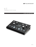
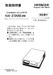
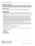
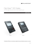
ic-2
USER
MANUAL
///////
Index
Important Safety Instructions
1-3
Side Panel Controls
10
Safety Cautions
1
Switches
11
Safety Warnings
1-3
Adjustments
11
Recycling Instructions
3
Inputs
11
System Includes
4
Outputs
11
Overview
5
Signal Schematics
12
Controls and I/O’s
6-11
Configurations
13-20
Top Panel Controls
6
Single Unit Setup
13-16
Mode Selection Controls
7
Multilingual System Setup
17-20
Microphone Controls
7
Limited Warranty
21
Headphone Controls
7
Specifications
22-23
Back Panel Controls
8
FAQ’s
24-25
Power
9
Contact Us
25
Switches
9
Indicator
9
Adjustment
9
Inputs
9
Outputs
9
Important Safety Instructions
Read these instructions. Keep these instructions. Heed all warnings. Follow all instructions.
sa f e t y C A U T I O N s
This product is designed to amplify sounds to a high volume level which could potentially cause hearing damage if used improperly. To protect your
hearing and the hearing of others:
1. Make sure the volume is turned down before putting on the earphone or headphone and then adjusting the volume to a comfortable level.
2. Set the volume level at the minimum setting that you need to hear.
3. If you experience feedback (a squealing or howling sound), reduce the volume setting and move the microphone away from the earphone or
headphone.
Do not allow children or other unauthorized persons to have access to this product.
sa f e t y W A R N I N G s
WARNING To reduce the risk of fire or electric shock, do not expose the system to rain or moisture. Do not use this apparatus near water. The
console shall not be exposed to dripping or splashing, and objects filled with liquids such as beverages shall not be placed on the console. Clean
only with a dry cloth.
CAUTION
RISK OF ELECTRICAL SHOCK — DO NOT OPEN
AVIS
!
RIQUE DE CHOC ELECTRIQUE. NE PAS OUVRIR
ATTENTION: POUR RÉDUIRE LE RISQUE DE DÉCHARGE ÉLECTRIQUE, NE
RETIREZ PAS LE COUVERCLE (OU CÔTÉS). IL NE SE TROUVE AL’INTÉRIEUR
AUCUNE PIECE POUVANT ETRE RÉPARÉE PAR L’USAGER. S’A DRESSER A
UN RÉPARATEUR COMPÉTENT.
CAUTION: TO REDUCE THE RISK OF ELECTRIC SHOCK,DO
NOT REMOVE COVER (OR SIDES). NO USER-SERVICABLE
PARTS INSIDE. REFER SERVICING TO QUALIFIED PERSONNEL.
///////////////////////////////////////////////////////////////////////////////
!
1
/////////////////////////////////////
/////////////////////////////////
Se r vici ng or attempting to ser vice this device will void the warran ty
Refer servicing to qualified personnel. Servicing is required when the console has been damaged in any way; if liquid has been spilled or objects
have fallen into the console, it has been exposed to rain or moisture, does not operate normally, or has been dropped.
Do not block any ventilation openings. Install in accordance with manufacturer’s instructions.
Do not install near any heat sources such as radiators, heat registers, stoves, or other apparatus that produce heat.
Use only attachments/accessories specified by the manufacturer.
Unplug the console during lightning storms or when unused for long periods of time.
Be advised that different operating voltages require the use of different types of line cord and attachment plugs. Check the voltage in your area and
use the correct type.
Use only the power supply provided by the manufacturer of this device. Other power supplies may have similar specifications, but may not be
equivalent in emissions ratings, in-rush current, etc. Use of an unapproved power supply may leave the device partially or completely inoperable,
and will void the warranty.
This apparatus has been designed with class-1 construction and must be connected to a main socket outlet with a protective earthing connection
( the third grounding prong ).
Protect the power cord from being walked on or pinched, particularly at plugs, receptacles, and near the power jack on the console.
This apparatus must be earthed.
The MAINS plug or an appliance coupler is used as the disconnect device, so the disconnect device shall remain readily operable.
For customers in the United States
WARNING: Use a three wire grounding type line cord like the one supplied with the product. Do not defeat the safety purpose of the polarized or
grounding-type plug. A polarized plug has two blades with one wider than the other. A grounding type plug has two blades and a third grounding
prong. The wide blade or the third prong are provided for your safety. If the provided plug does not fit into your outlet, consult an electrician for
replacement of the obsolete outlet.
This equipment has been tested and found to comply with the limits for Class A digital device, pursuant to part 15 of the FCC rules.
For customers in Canada
This Class A digital device meets all requirements of the Canadian Interference-Causing Equipment Regulations.
Cet appareil numérique de la classe A respecte toutes les exigencies du Règlement sur le matériel brouilleur du Canada.
R ec y cling I ns t ruc t ions
Help Williams Sound protect the environment! Please take the time to dispose of your equipment properly.
Product Recycling for Customers in the European Union:
Please do NOT dispose of your Williams Sound equipment in the household trash. Please take the equipment to a electronics recycling center; OR
return the product to the factory for proper disposal.
///////////////////////////////////////////////////////////////////////////////
3
/////////////////////////////////////
/////////////////////////////////
System Includes
d
c
Figure 1: Packing List
f
b
a · IC-2 Interpreter Console
b · (1) 25 foot (7.6 meter) CAT5 patch cable, WCA 091
c · 18VDC international desktop style power supply, TFP 044
Operates on 100-240VAC, 50-60Hz
d · Power supply line cord, WLC 004 (US), WLC 005 (EU), WLC 006 (UK), or WLC 007 (AU)
e · 5-year Warranty Card, FRM 404
f · Manual and user guide, MAN 152
a
e
Overview
The IC-2 is an audio control console for simultaneous language interpretation. A single unit allows one or two interpreters to monitor floor or relay
sources, activate microphone inputs, and route their interpretation to one of two audio output channels. The system is ideal for presentation-style
conferences where all interpreters speak a common or “Relay” language. The IC-2 has many helpful, new features that simplify setup, improve
audio quality and increase flexibility:
· CAT5 bus allows quicker setup with simplified cabling, easy cascading to support additional interpreters, and no external distribution amplifiers. · Soft-touch buttons provide smoother, quieter operation.
· RCA jacks make recording the interpretation simple.
· Multiple microphone and headphone connection options for each interpreter make using your existing equipment a snap.
· Supports an array of hands-free headphones and microphone.
· Individual controls for each interpreter ensure optimal listening and output levels.
· Peak level indicator light allows technicians to easily ensure audio output levels are consistent.
· Automatic interlock of the relay channel.
· Selectable feedthrough ( automatic routing ) of the Floor signal onto unoccupied channels.
The IC-2 can be used with Williams Sound FM, IR and Digi-Wave transmitters for portable installations. It is designed to meet international standards for interpretation consoles and is backed by a 5-year warranty. If you need assistance with this product, contact Williams Sound Customer
Service at 1.800.843.3544 or 952.943.2252.
///////////////////////////////////////////////////////////////////////////////
5
/////////////////////////////////////
/////////////////////////////////
Top Panel Controls
“relay in use” LED
treble
bass
treble
Figure 2: Top Panel
bass
volume
volume
norm / relay output
norm / relay output
relay input
relay input
floor input
mic on
interpreter ( a )
mute
mic on
interpreter ( b )
floor input
M o d e S elec t ion C on t rols
I n puts
· Floor – headphone monitors Floorl.
· Relay – headphone monitors Relay.
O U T puts
· Norm / Relay – Outputs to Relay when enabled. Otherwise output defaults to Norm.
M icro p h one C on t rols
· Mic On – push and release to turn microphone on or off. Microphones are interlocking: you can only turn on your microphone if the other is off.
· Mute – “cough button” press and hold to mute microphone.
Hea d p h one C on t rols
· Volume – adjusts headphone output level.
· Bass – boosts or cuts bass tone level to headphones.
· Treble – boosts or cuts treble tone level to headphones.
in d ica t or
· “Relay In Use” LED — indicates when Relay Output is in use.
///////////////////////////////////////////////////////////////////////////////
7
/////////////////////////////////////
/////////////////////////////////
Back Panel Controls
Figure 3: Back Panel
relay feedthrough
norm feedthrough
norm out RCA jack
relay out RCA jack
IC-2 bus in
XLR floor in
ground lift
power jack
peak level indicator
XLR norm out
XLR relay out
IC-2 bus out
floor in level control
Power
· 18VDC, 1A Power Jack – 2.5 mm ID barrel power jack connects to TFP 044.
S wi t c h es
· Norm Feedthrough –routes the audio from Floor onto Norm when Norm Output is not in use. See figures 6 and 7 and note on page 15 and 16 for more info.
· Relay Feedthrough –routes the audio from the Floor onto the Relay Out XLR jack when Relay Output is not in use. See figures 6 and 7 and note on page
15 and 16 for more info.
· Ground Lift –safely breaks the connection between chassis and audio grounds internal to the IC-2 to help technicians debug tricky ground-loops that
cause hum. Use only if needed for best audio performance. The default position is down or “GND”.
I n d ica t or
· Peak level indicator – When gain levels are set correctly, LED blinks only at natural peaks of speech to indicate optimal ouptut level of active audio source.
A d j us t men t
· Floor Level control – allows the technician to set the input level.
Inputs
· Floor In XLR Jack – balanced or unbalanced audio signal in from the PA system, mixer, or microphone.
Note: while the IC-2 will work with balanced or unbalanced audio on Floor In; balanced, line-level audio is desirable for best performance.
· IC-2 Bus In – CAT5 bus routes Floor and Relay signals between IC-2’s.
Outputs
· Norm Out XLR Jack – balanced, line level audio out to transmitter.
· Norm Out RCA Jack – mono audio from interpreter only ( no feedthrough ) out to recording device.
· Relay Out XLR Jack – balanced, line level audio out to transmitter.
· Relay Out RCA Jack – mono audio from interpreter only ( no feedthrough ) out to recording device.
· IC-2 Bus Out – CAT5 bus routes Floor and Relay signals between IC-2’s.
///////////////////////////////////////////////////////////////////////////////
9
/////////////////////////////////////
/////////////////////////////////
Side Panel Controls
Figure 4: Side Panel
XLR mic jack
phantom power
XLR mic level
electret mic level
electret mic jack
headphone jack
electret mic + headphone jack
S wi t c h es
· Phantom Power ( Simplex ) – enables 12VDC “simplex” power to XLR Microphone Input.
A d j us t men t s
· XLR Microphone Level Control – allows the technician to set the input level.
· Electret Microphone Level Control – allows the technician to set the input level of both the pink 3.5mm electret microphone and the 3.5mm TRRS
microphone + headphone jack
Inputs
· XLR Microphone Jack – balanced microphone with optional phantom power.
· Electret Microphone Jack ( Pink ) – 3.5mm TRS “mini-plug” electret mono or stereo microphone.
· Microphone + Headphone Jack ( Black ) – 3.5mm TRRS “mini-plug” electret microphone for i-Phone® style hands-free electret mics.
Only accomodates mics with this pinout.
Outputs
· Headphone Jack ( Green ) – 3.5mm TRS “mini-plug” mono or stereo headphone jack.
· Microphone + Headphone Jack ( Black ) – 3.5mm TRRS “mini-plug” stereo headphone.
///////////////////////////////////////////////////////////////////////////////
11
/////////////////////////////////////
/////////////////////////////////
Signal Schematics
Signal Distribution
PA
FLOOR
FLOOR
IC-2
RELAY
Input Selection
FLOOR
IC-2
IC-2
RELAY
FLOOR SELECTED
FLOOR IN
IC-2
INTERPRETER
RELAY SELECTED
RELAY BUS IN
Output Selection
IC-2
INTERPRETER
RELAY ON
MIC IN
IC-2
RELAY OUT
IC-2
NORM OUT
RELAY OFF
MIC IN
Figure 5: Signal schematics
Single Unit Setup
A single unit can be used for simple or bilingual situations. In a simple configuration , the majority of the audience speaks the language of the orator,
and listens through the PA system. A minority of the audience is in need of language interpretation, but they all speak a common language.
In a bilingual configuration, the language spoken at the podium will switch between two languages over the course of the day. This leaves the entire
audience in need of interpretation at some point. Each member of the audience is given a receiver set to the appropriate language channel.
S im p le C on f igura t ion I ns t ruc t ions
1. Plug the line cord into the TFP 044 power supply that comes with your IC-2. Connect the plug on the power supply to the DC power jack on the
rear panel of the IC-2. Plug the line cord into an AC power outlet (100 to 240 V, 50-60Hz).
2. Plug a line level audio signal from the floor language source into the Floor In XLR Jack on the rear panel. Make sure there is audio coming from
this source for testing purposes.
3. Set the Norm and Relay Feedthrough switches in the “ON” position and adjust the Floor In level control until the green peak level indicator LED by
the Norm Out XLR jack is blinking at natural peaks of speech in the audio.
4. Connect the Norm Out XLR jack to the audio input of an IR Modulator or FM Transmitter. Turn on the modulator or transmitter and set it up according to its directions.
5. Turn the headphone volume control all the way down and plug in stereo or mono headphones.
6. Have the interpreter who will be using the console listen to the headphones and slowly turn up the volume until the Floor audio is at the lowest
comfortable level.
7. Turn the level control associated with the microphone input the interpreter will be using all the way down (counter-clockwise).
///////////////////////////////////////////////////////////////////////////////
13
/////////////////////////////////////
/////////////////////////////////
8. Plug the interpreter’s microphone in.
9. Turn the microphone on by pushing its Mic On button.
10. Have the interpreter sit comfortably and speak into the microphone at a natural level. Turn the level control for this microphone clockwise until
the peak indicator on the back panel blinks at natural peaks in the interpreter’s speech.
11. Ensure the audio indicator on the transmitter is flashing and you are able to hear the signal with a receiver. Adjust the transmitter input level
control if necessary.
B ilingual C on f igura t ion I ns t ruc t ions
12. Connect a transmitter to the Relay Out XLR jack and set it up according to its instructions. Assign a language to each output channel. Example:
Norm Out is Spanish, and Relay Out is English. Have the interpreters enable Relay Output to interpret into English, and enable Norm Output to
interpret into Spanish.
Not e o n F e e dthrou g h :
With Norm and Relay Feedthrough switches on, the Floor channel is automatically routed to any unoccupied channel. This keeps language channels
active at all times, allowing audience members to listen to their language channel all day and hear their language from either the presenter directly or
an interpreter, as appropriate.
In a simple configuration, this feature can be easily used to provide hearing assistance. Simply hook a transmitter up to Relay Out and make sure
Relay Feedthrough is on. Provide audience members in need of sound amplification with receivers set to the Relay transmitter’s channel. Since this
channel will not be used by the interpreters, it will have the Floor audio automatically routed onto it.
FLOOR IS ENGLISH
XL
Rf
rom
PA
ut
yo
ela
r
o
ht
int
ug
erp
ret
hro
t
ati
d
e
on
e
f
ch
r
o
1
flo
to
ic
m
rm
no
t
ou
int
erp
ret
ati
on
ch
2
floor input selected
norm output selected
floor feedthrough to relay out
Figure 6: Bilingual configuration A
///////////////////////////////////////////////////////////////////////////////
15
/////////////////////////////////////
/////////////////////////////////
F L O O R S W I T C H E S T O S PA N I S H
XL
Rf
rom
PA
t
ou
ay
rel
o
t
c
mi
int
erp
ret
ati
on
ch
1
or
flo
floor input selected
relay output selected
floor feedthrough to norm out
Figure 7: Bilingual configuration B
rm
no
to
h
g
ou
hr
dt
e
e
f
t
ou
int
erp
ret
ati
on
ch
2
Multilingual System Setup
In multilingual configuration, the audience needs to listen to interpretations of the presentation in multiple languages. There are three multilingual
setups:
In a simple multilingual configuration, the language spoken at the podium will remain constant and is understood by all interpreters. A relay transmitter is not required unless desired for hearing assistance.
In a relay multilingual configuration, the language spoken at the podium will remain constant, but is not spoken by all interpreters. A simultaneous
interpretation of a “Relay” language spoken by all interpreters is necessary. This interpretation is routed via the CAT-5 bus to all other interpreters,
who interpret sequentially. A relay transmitter is usually desirable.
In a switching relay multilingual configuration, the language spoken at the podium will change and is not spoken by all interpreters. A simultaneous
interpretation of a “Relay” language spoken by all interpreters is necessary. Over the course of the day the interpreter which can provide this relay will
change. A relay transmitter is necessary.
M ult ilingual C on f igura t ion I ns t ruc t ions
1. Connect the audio signal from the PA system or mixer to the first unit in the system.
2. Connect the IC-2 Bus Out on this unit to the IC-2 Bus In on the second unit using the CAT-5 cable included with your system. Connect the IC-2
Bus Out on the second unit to the IC-2 Bus In on the third unit, and so forth.
///////////////////////////////////////////////////////////////////////////////
17
/////////////////////////////////////
/////////////////////////////////
3. Follow the Single Unit Setup instructions for each unit in the chain, plugging them in to power only after the bus connections have been made.
4. If Relay will be used, connect a transmitter for the Relay channel to any Relay Out XLR jack in the chain. Turn on the transmitter and set it up according to its directions.
Not e o n P rop e r S e tup of th e I C - 2 B us :
Be certain to follow steps 2 and 3 in order. The audio bus that carries the floor signal between units is unidirectional. The Floor audio MUST be connected to the Floor In XLR jack on the first unit in the daisy chain for the audio flow between units to work correctly. Be sure to connect all units via
the CAT-5 bus BEFORE plugging them in to power.
FLOOR IS ENGLISH
XL
Rf
rom
PA
ut
yo
ela
or
t
h
ug
int
erp
hro
ret
edt
ati
e
f
on
r
o
ch
1
flo
rm
no
to
ic
m
floor input selected
norm output selected
t
ou
flo
or
bu
s
rel
ay
bu
s
floor feedthrough to relay out
int
erp
ret
ati
on
ch
2
int
erp
ret
ati
on
ch
3
to
ic
m
Figure 8: Multilingual configuration A
floor input selected
norm output selected
rm
no
t
ou
FLOOR CHANGES TO FRENCH
XL
Rf
rom
PA
t
ou
ay
rel
o
t
c
mi
int
erp
ret
ati
on
ch
1
rm
no
to
ic
m
relay input selected
norm output selected
Figure 9: Multilingual configuration B
t
ou
flo
or
bu
s
rel
ay
bu
s
floor input selected
relay output selected
floor feedthrough to relay out
int
erp
ret
ati
on
ch
2
h
ug
ro
h
t
ed
fe
or
o
fl
y
la
re
to
t
ou
int
erp
ret
ati
on
ch
3
Limited Warranty
The exclusions and limitations set out above are not intended to, and should not be
Williams Sound products are engineered, designed, and manufactured under care-
with applicable law by a court of competent jurisdiction, the validity of the remaining
fully controlled conditions to provide you with many years of reliable service. Williams
portions of this Disclaimer of Warranty shall not be affected, and all rights and obliga-
Sound warrants the Interpreter Console against defects in materials and workman-
tions shall be construed and enforced as if this Limited Warranty did not contain the
ship for FIVE (5) years. During the first five years from the purchase date, we will
particular part or term held to be invalid.
construed so as to contravene mandatory provisions of applicable law. If any part or
term of this Disclaimer of Warranty is held to be illegal, unenforceable, or in conflict
promptly repair or replace the Interpreter Console.
If you experience difficulty with your system, call Toll-Free for Customer Assistance:
Microphones, earphones, headphones, batteries, chargers, cables, carry cases, and
all other accessory products carry a 90-day warranty.
1.800.328.6190
WILLIAMS SOUND HAS NO CONTROL OVER THE CONDITIONS UNDER WHICH
If it is necessary to return the system for service, your Customer Service Representa-
THIS PRODUCT IS USED. WILLIAMS SOUND, THEREFORE, DISCLAIMS ALL
tive will give you a Return Authorization Number (RA) and shipping instruction.
WARRANTIES NOT SET FORTH ABOVE, BOTH EXPRESS AND IMPLIED, WITH
Pack the system carefully and send it to:
RESPECT TO THE INTERPRETER Console, INCLUDING BUT NOT LIMITED TO,
ANY IMPLIED WARRANTY OF MERCHANTABILITY OR FITNESS FOR A PARTICU-
Williams Sound, LLC
Attn: Repair Dept.
10300 Valley View Road
Eden Prairie, MN 55344 USA
LAR PURPOSE. WILLIAMS SOUND SHALL NOT BE LIABLE TO ANY PERSON
OR ENTITY FOR ANY MEDICAL EXPENSES OR ANY DIRECT, INCIDENTAL OR
CONSEQUENTIAL DAMAGES CAUSED BY ANY USE, DEFECT, FAILURE OR MALFUNCTIONING OF THE PRODUCT, WHETHER A CLAIM FOR SUCH DAMAGES
IS BASED UPON WARRANTY, CONTRACT, TORT OR OTHERWISE, THE SOLE
REMEDY FOR ANY DEFECT, FAILURE OR MALFUNCTION OF THE PRODUCTS
Your warranty becomes effective the date you purchase your system. Your returned
REPLACEMENT OF THE PRODUCT. NO PERSON HAS ANY AUTHORITY TO BIND
warranty card is our way of knowing when your warranty begins. It also gives us
WILLIAMS SOUND TO ANY REPRESENTATION OR WARRANTY WITH RESPECT
important information about your system including the serial number. This informa-
TO THE INTERPRETER Console. UNAUTHORIZED REPAIRS OR MODIFICATIONS
tion will help us serve you better in the future. Please take a moment to complete
WILL VOID THE WARRANTY.
and mail the warranty card. Thank you.
///////////////////////////////////////////////////////////////////////////////
21
/////////////////////////////////////
/////////////////////////////////
Specifications
Dimensions/Weight/Color
10” (25.4cm) x 6.35” (6.2cm) x 2.45” (6.2cm) / 3.4 lbs (1.5 kg) / Black and Silver
Power
External Power Supply, 18VDC Desktop Style Switching Inverter, 110-240VAC, 50-60Hz, 1A
INPUTS / OUTPUTS
Floor In
3-pin XLR female jack, balanced (or unbalanced) input with 24k Ω differential input impedance, max balanced input is
+19dBu. Rotary pot gain adjust 0±10dB.
IC-2 Bus In / Out
CAT5 8p8c RJ45 female receptacle, distributes balanced line level Floor and Relay audio to another IC-2
XLR Microphone Inputs
3-pin XLR female jack, balanced (or unbalanced) input. Switchable 12VDC simplex power. Rotary pot gain adjust of 58
dB max, 2.4k Ω balanced input impedance, maximum balanced input is +19 dBu
3.5mm Electret Microphone Inputs ( Pink )
Stereo 3.5 mm TRS phone jack, for electret condenser microphones. Bias is 3.7VDC through 2.7k Ω. Rotary pot gain
adjust is 40dB max.
3.5mm TRRS Headphone / Microphone Output ( Blk )
3.5mm TRRS phone jack, Tip = Left, Ring 1 = Right, Ring 2 = GND, Sleeve = Mic. 40mW max power into 32 Ω stereo
headset. Electret condenser microphone bias is 3.7VDC through 2.7kΩ. Rotary pot gain adjust is 40dB max.
3.5mm Headphone Output ( Green )
3.5mm TRS phone jack, mono or stereo headphone, 8 Ω minimum. 190mW max power into 32 Ω stereo headphones.
Norm Out, Relay Out
3-pin XLR male jack, balanced output. Max output is +19dBu into 600 Ω balanced load impedance.
RCA Jacks
Red RCA jack for recording “Norm Out” signal ( interpreter audio only, no feedthrough ). White RCA jack for recording
“Relay Out signal ( interpreter audio only, no feedthrough ).
CONTROLS
Volume
Left and Right rotary, controls headphone volume
Bass and Treble Tone
Left and right rotary with center detent, controls headphone bass and treble tone levels.
Mute
Push button, backlit red, mutes left and right mics while pressed.
Mic On
Push button, backlit bright red, activates microphone. Right and left Mic On buttons are interlocked; mic can only
be turned on if the other is off.
Floor Input, Relay Input
Push buttons, backlit blue, select listening language group. Listening modes are either/or: turning one on disables
the other.
Relay Output
Push button, backlit yellow, selects microphone output language group: light on = Relay Out, light off = Norm Out.
Gain Adjust
Rotary gain pots control level of microphone and Floor audio.
Phantom Power
Slide switch enables 12VDC Simplex power to XLR microphone.
Norm Feedthrough
Slide switch enables Floor feedthrough to Norm Out XLR jack.
Relay Feedthrough
Slide switch enables Floor feedthrough to Relay Out XLR jack.
Ground Lift
Slide switch disconnects Chassis and Audio Grounds internal to the console.
I N D I C AT O R
Peak Level Indicator
Green LED on back panel indicates optimal audio output level on Norm Out XLR when blinking.
Relay Output in Use Indicator
Yellow LED on front panel indicates when Relay Output is in use.
AUDIO OUTPUT
Frequency Response
45Hz to 20kHz, +0/-3dB re: 1kHz with flat bass/treble
Distortion at 1kHz
<0.5% THD @ full power
Signal to Noise Ratio
>82dB @ 1kHz
Crosstalk Attenuation
>63dB @ 1kHz
Tone Controls
Bass: +12dB Boost or -12dB Cut @ 100Hz
Treble: +12dB Boost or -12dB Cut @ 10kHz
Approvals and Declarations
CE, FCC, Industrie Canada, RoHS, C-Tick, CB
Warranty
5 years, parts and labor (90 days on accessories)
Note: 0dBu = 0.775VRMS
///////////////////////////////////////////////////////////////////////////////
23
/////////////////////////////////////
/////////////////////////////////
FAQ’s
Q: Should I use shielded or unshielded CAT5 cable?
A: We supply unshielded CAT5 because of the tendency of the
shielding to create ground loops that cause hum in audio systems. Depending on your setup, in areas of high electromagnetic interference, shielded cable may be beneficial. Find the cable
that optimizes sound quality in your system setup.
Q: When should I use the Ground Lift Switch?
A: Audio systems frequently have multiple components plugged
into the same electric circuit and share a ground. This can
create a ground loop that introduces 50 or 60 cycle hum into
the audio. Many distribution amplifiers have a ground lift switch
to help prevent this problem by “breaking the loop”. Since the
IC-2 is used without need for a distribution amplifier, we added a
ground lift switch to help technicians troubleshoot this common
problem.
Q: What can I do when having trouble getting a consistent audio
output level?
A: Optimizing audio output levels so that the audience doesn’t have
to constantly adjust the volume of their receivers has always
been one of a technician’s biggest challenges. The PA system
doesn’t have the same audio input level as the interpreters’
microphones. The interpreters, for that matter, frequently have
different microphones and speak at different levels. This creates
a broad range of input signal strength for technicians to balance.
To help level the signal strength without sacrificing audio quality,
we’ve included level controls to adjust every audio source that
can be output to a transmitter from the IC-2. The peak level
indicator will blink more often the higher the output amplitude.
To use it most effectively, make sure to set up the actual individuals and microphones that are going to be in use. Have your
interpreters get comfortable before you test – slumping away
from their microphone as they relax during the day will decrease
their volume level. Turn the pots until the light blinks at peaks of
speech for each input source. If your transmitter has compression, gain, or other adjustments, experiment with the system as
a whole ahead of time to get a feel for which settings produce
the best, most consistent output for the audience.
Q: Some of the units in my system are not getting the Floor signal.
Why doesn’t it work?
is on one side of the console only, that headphone is likely the
culprit. The thermal shutdown can be reset, simply:
· Replace the suspect headset with a known good
headset.
· Unplug the IC-2’s power and plug it back in ( this will reset the audio chip and turn it back on after the
shutdown ).
· Check to see if the problem has gone away. If not, repeat
with the other headset.
A: The Floor signal only travels along the bus between units in one
direction. You have to plug the Floor audio into the first unit in
the “daisy chain” for it to be correctly transferred to all units. You
can identify this unit by the fact that there is nothing plugged into
its IC-2 Bus In jack
Q: The speaker at the podium’s voice is not coming out on the
relay language transmitter when he is speaking the relay language. What should I do?
Contact us
A: Make sure to turn on Relay Feedthrough switch on the unit the
relay transmitter is connected to.
Q: The headphone on one side of my console became intermittent
and then both headphones shut down. Why did the audio cut
out?
800.843.3544 (U.S.A.)
A: The IC-2 has a protection circuit built in that will shut down the
headphone circuitry if a bad headset is plugged in ( one that
would damage circuitry ). If you experience intermittent audio on
one or both sides of the console, or both headphones turn off,
it’s probably thermal shutdown feature kicking in. It the problem
[email protected]
///////////////////////////////////////////////////////////////////////////////
+1.952.943.2252
williamssound.com
Williams Sound, LLC
10300 Valley View Rd.
Eden Prairie, MN 55344
25
/////////////////////////////////////
/////////////////////////////////
© 2011, Williams Sound, LLC Man 152 E