1
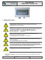
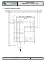
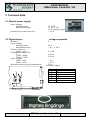
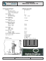
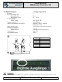
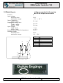
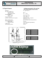
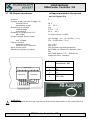
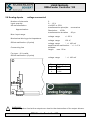
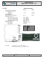
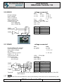
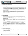
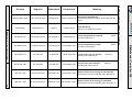
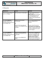
USER MANUAL
RMA-Feeder Controller 105
USER MANUAL
VIBRATION CONTROL
RMA - Feeder Controller 105
RMA-Feeder Controller 105
1
USER MANUAL
RMA-Feeder Controller 105
IMPORTANT NOTES
Electrical danger within the meaning of this documentation or the warning labels on the
product itself respectively means that death, serious injury or considerable material
damage may occur if the respective measures of precaution are not taken.
Mechanical danger within the meaning of this documentation or the warning labels on the
product itself respectively means that death, serious injury or considerable material
damage may occur if the respective measures of precaution are not taken.
Disconnecting voltaged parts within the meaning of this documentation means that
before maintenance, repair and installation work, the voltage must be switched off and
secured against being switched on again.
Qualified Staff
According to this user manual and the labels on the product itself, qualified staff includes those
persons, who are familiar with the installation, mounting, initial operation and operation of the device
as well as the dangers associated with this and who have the qualifications necessary for their work,
such as:
1. Training or instruction or authorisation respectively to switch electric circuits and devices on and
off, ground and mark them according to the standards of safety engineering.
2. Training and instruction according to the standards of safety engineering concerning the care and
use of adequate safety equipment.
3. First aid training
Intended Use
The RMA-Feeder Controller 105 must only be used for the control of our KÖBRATOR – oscillating rails
and for the processing of digital and analog signals.
Warranty
Adherence to the user manual is the pre-condition for a failure-free operation and for the settlement of
possible claims under the warranty. Therefore, please study the user manual before you operate the
device.
Disposal
Dispose of the RMA-Feeder Controller 105 depending on composition and existing regulations as:
RMA-Feeder Controller 105
2
USER MANUAL
RMA-Feeder Controller 105
-steel scraps
-aluminium
-copper
-synthetic material
-electronic scraps
RMA-Feeder Controller 105
3
USER MANUAL
RMA-Feeder Controller 105
Index
IMPORTANT NOTES ....................................................................................................................................................... 2
Index ................................................................................................................................................................................... 4
1. Safety Instructions.......................................................................................................................................5
2. Installation...................................................................................................................................................6
2.1 Electrical Installation ..........................................................................................................................................6
2.2 Connection Diagram (Example) ........................................................................................................................7
3. Technical Data ............................................................................................................................................8
3.1 Electric power supply..........................................................................................................................................8
3.2 Digital-Inputs
voltage-separated ................................................................................................................8
3.3 Functional Inputs
3.4 Digital-Outputs
3.5 Digital-Inputs
voltage-connected ..........................................................................................................9
voltage-separated ...........................................................................................................10
voltage-separated to the system .......................................................................................11
3.6 Digital-Outputs
voltage-separated to the system ....................................................................................12
3.7 4Q-Output transformer
3.8 Analog-Inputs
3.9 CAN
voltage-separated to the system ......................................................................13
voltage connected .................................................................................................................14
voltage-separated.........................................................................................................................15
3.10 RS232
voltage-connected .....................................................................................................................16
3.11 RS485
voltage-connected .....................................................................................................................16
4. Displays and Control Keys ........................................................................................................................17
4.1 Automatic Operation ........................................................................................................................................17
4.2 Setup Operation ................................................................................................................................................17
4.3 Deletion of Malfunctions...................................................................................................................................17
4.4 Setting of the Vibration ....................................................................................................................................18
4.5 Status – Display of the I-Os ..............................................................................................................................18
4.6 Saving the Frequency or the Performance Settings Respectively. ................................................................18
4.7 Set up values of Pneumasort times ..................................................................................................................19
5. Troubleshooting ........................................................................................................................................20
5.1 Error list.............................................................................................................................................................21
RMA-Feeder Controller 105
4
USER MANUAL
RMA-Feeder Controller 105
1. Safety Instructions
The RMA-FEEDER CONTROLLER 105 controls oscillating mechanical parts
(KÖBRATOR), which may be dangerous.
Safety measures and safety devices must correspond with the valid national regulations
(e.g. VDE 0100 T410 /VDE 0113 T1 or EN 60204 / VDE 0160 respectively)
Necessary safety measure: grounding of the RMA-Feeder Controller 105
Necessary safety device:
circuit breaker
If you do not wish to install the device immediately, but instead wish to store it:
The storage place must be dry and clean;
the storage temperature must be between –25°C and +85°C.
Check the device immediately for damaged packaging. Send complaints concerning
damages immediately.
See to it that damaged products are not operated!
The connection, initial operation, as well as maintenance and repair work must only be
executed by qualified expert staff, taking into consideration this manual and all other
connection diagrams belonging to the RMA-FEEDER CONTROLLER 105 and the presently
valid national /international regulations (safety / accident prevention)
The RMA-Feeder Control 105 is built for 24V DC operation.
We reserve the right to change technical data and constructions beneficial to technical
progress.
RMA-Feeder Controller 105
5
USER MANUAL
RMA-Feeder Controller 105
2. Installation
2.1 Electrical Installation
Please be sure to note the safety instructions in Chapter 1 during the electrical installation!
THE DEVICE MUST BE GROUNDED.
Please be sure to note the safety instructions in Chapter 1 during the electrical
installation!
As a connecting line for the KÖBRATOR only the supplied cable must be used. Only one
Köbrator may be operated for each magnetic output of the Feeder Controller.
Connect all electric connections according to the connection diagram
RMA-Feeder Controller 105
6
USER MANUAL
RMA-Feeder Controller 105
2.2 Connection Diagram (Example)
RMA-Feeder Controller 105
7
USER MANUAL
RMA-Feeder Controller 105
3. Technical Data
3.1 Electric power supply
Input voltage
Nominal value
admissible range
24 V DC
+/- 25 % incl.
10 % residual ripple
≤ 0.6 A
Drawing of current from 24 V
3.2 Digital-Inputs
voltage-separated
Number
Input voltage
Nominal value
admissible range
Fan-in current at
HIGH - level
Propagation delay time
t LOW - HIGH
t HIGH - LOW
Input voltage
LOW - level
HIGH - level
Mechanical driving point impedance
I3
24 V
- 30 ... + 30 V
6.1 mA
3.5 ms
2.8 ms
≤5V
≥ 15 V
3.9 kΩ
Actuator supply
1
BUCHSE
I0
4
Pin:
1
2
3
4
5
6
Inputs
I0
I1
I2
I3
0V
+ 24V_A
0V
+24V_A
1
6
5 4
3
2
1
1
1
RMA-Feeder Controller 105
8
USER MANUAL
RMA-Feeder Controller 105
3.3 Functional Inputs
voltage-connected
Number
Standard Inputs
Incremental supply input
Timer- / counter inputs
4, usable as
4
1
4
Input voltage
Nominal value
admissible range
24 V
- 30 ... + 30 V
Fan-in current at
HIGH - level
5.2 mA
Input frequency
at duty cycle 0.5
⌠ 25 kHz
Propagation delay time
Standard inputs
tLOW - HIGH
tHIGH - LOW
15 µs
15 µs
Input voltage
LOW - level
HIGH - level
⌠5V
∫ 15 V
Selector shaft
U LOW - HIGH
U HIGH - LOW
13.1 V
9.5 V
Mechanical driving point impedance
4.6 kΩ
Input signals VRZ
2-Phase-square
moved by 90°
1 reset pulse
4 - fold
24 V DC, +/-25 %, 150 mA
Gating
Sensor supply
Dig. In Fun.-In
I4
IN 0
I5
IN 1
I6
IN 2
I7
IN 3
GND
+ 24 V
VRZ
CH-A
CH-B
CH-0
1
BUCHSE
CH-A
CH-B
CH-0
Pin:
1
2
3
4
5
6
+24V
1
1
6
5
1
4 3 2 1
RMA-Feeder Controller 105
9
USER MANUAL
RMA-Feeder Controller 105
3.4 Digital-Outputs
voltage-separated
Number
On-load voltage Vin
Nominal value
admissible range
Output voltage
HIGH - level
LOW - level
Fan-out current
Parallel connection of outputs
6
24 V
18 ... 30 V
min. Vin-0,2 V
max. 2 µA · RL
max. 500 mA
possible, max. 4 outputs
with Itotal = 2 A
yes, thermal overload protection
Short circuit-proof
Sampling frequency
ohmic load
inductive load
Lamp load
simultaneity factor
0V
100 Hz
2 Hz (induction-dependent)
max. 6 W
100 %
Pin:
1
2
3
4
5
6
0V
Outputs
Q0
Q1
Q2
Q3
Q4
Q5
+24V
0V
1
1
6
!
5 4
3
2
1
1
6 5
W ARNING:
Voltage negative feed at the outputs can lead to the destruction of the output drivers.
RMA-Feeder Controller 105
10
USER MANUAL
RMA-Feeder Controller 105
3.5 Digital-Inputs
voltage-separated to the system
and to 4Q-output transformers
Number
Input voltage
Nominal value
admissible range
Fan-in current at
HIGH - level
Propagation delay time
t LOW - HIGH
t HIGH - LOW
Input voltage
LOW - level
HIGH - level
Mechanical driving point impedance
Actuator supply
Nominal value
admissible range
I3
I0
4
24 V
- 30 ... + 30 V
6.1 mA
3.5 ms
2.8 ms
≤5V
≥ 15 V
3.9 kΩ
24 V
18 ... 30V
Pin:
1
2
3
4
5
6
Inputs
I8
I9
I 10
I 11
0V
+ 24 V
0V
+24V
1
1
6
5 4
3
2
1
RMA-Feeder Controller 105
11
USER MANUAL
RMA-Feeder Controller 105
3.6 Digital-Outputs
voltage-separated to the system
and to 4Q-output transformers
Number
On-load voltage Vin
Nominal value
admissible range
Output voltage
HIGH - level
LOW - level
Fan-out current
parallel connection of outputs
4 (1 group à 4)
24 V
18 ... 30 V
min. Vin-0.2 V
max. 2 µA · RL
max. 500 mA
possible, max. 4 outputs
with Itotal = 2 A
yes, thermal overload protection
Short circuit-proof
Sampling frequency
ohmic load
inductive load
Lamp load
Simultaneity factor
100 Hz
2 Hz (induction-dependant)
max. 6 W
100 %
Q0
Q3
0V
0V
+24V
Pin:
1
2
3
4
Outputs
Q6
Q7
Q8
Q9
Pin:
5
6
Outputs
0V
+ 24 V
0V
1
1
4
3
2
1
6
5
RMA-Feeder Controller 105
12
USER MANUAL
RMA-Feeder Controller 105
3.7 4Q-Output transformer
voltage-separated to the system
and to Digital IO’s
Number
Voltage supply on-load voltage Vin
nominal value
admissible range
Monitoring of voltage
undervoltage
overvoltage
Drawing of current from 24 V
per output
Output voltage (ohmic load)
min. voltage
Fan-out current
constant current
pulse current 1 second
Short circuit-proof
Sampling frequency outputs
2
24 V
18 ... 30 V
yes
3.5 V ... 7 V
33 V ... 43 V
on-load current + 0.02A
typ. voltage Vin - (0.125 Ohm * I load )
Vin - (0.300 Ohm * I load )
min. 2.5 A
typ. 4.4A
yes, thermal overload protection
per PW M ca. 20 kHz für Motoren (Var 06)
per PW M approx. 0.5 ... 600 Hz for
magnetic valve, vibration
Pin:
Optokoppler
4Q-Endstufe
M2M2+
M1M1+
0V (4Q)
+24V (4Q)
M1M2+
M2-
M1+
0V
24 V
4Q-Endstufe
1
2
3
4
5
6
4Q Output
(2 channels, -06)
1
6 5 4
!
3
2 1
WARNING:
Voltage negative feed at the outputs can lead to the destruction of the output drivers.
RMA-Feeder Controller 105
13
USER MANUAL
RMA-Feeder Controller 105
3.8 Analog-Inputs
voltage connected
Number of channels
Input quantity
AD-transformation
2
0 ... 10 V
via ADC to CPU
transformation principle
successive
Resolution 10 Bit
transformation duration
20 µs
Approximation
Max. Input range
voltage range
+/- 20 V
voltage range
136 kΩ
Mechanical driving point impedance
Offset malfunction (0-point)
voltage range
≤ +/- 100 mV
amplification malfunction ≤ +/- 1.0 %
shielded
length
max. 50 m
Connecting line
For type –10 is valid:
Offset malfunction (0-point)
voltage range
Pin:
1
2
3
4
≤ +/- 100 mV
Analog-Input
AI 0
GND
AI 1
+ 10V
+
-
10 V
1
1
4 3 2 1
!
W ARNING:
Voltage negative feed at the outputs can lead to the destruction of the output drivers.
RMA-Feeder Controller 105
14
USER MANUAL
RMA-Feeder Controller 105
3.9 CAN
voltage-separated
Output differential voltage
Input differential voltage
recessive
dominant
Input-Offset voltage
(to CAN-GND)
Input differential resistance
Transmission rate
up to 15 m cable length
up to 50 m cable length
up to 150 m cable length
up to 350 m cable length
Number participants
Connecting line
up to 100 m
up to 350 m
min.
+ 1.5 V
max.
+3V
-1V
+1V
+ 0.4 V
+5V
+/- 6 V
20 kΩ
100 kΩ
Pin:
1
2
3
4
CAN
CANL
CANH
RT
0V-CAN
0V-CAN
RT
CANH
CANL
1
BUCHSE
max. 1 MBit
max. 500 kBit
max. 250 kBit
max. 125 kBit
max. 64
shielded, twisted
0.25 mm²
0.5 mm²
1
1
4 3 2 1
Terminals:
by connection of RT via a bridge
to CANH at the ends of the CAN-network.
RMA-Feeder Controller 105
15
USER MANUAL
RMA-Feeder Controller 105
3.10 RS232
voltage-connected
min.
+/- 3 V
+/- 3 V
Output voltage
Input voltage
Fan-out current
Input resistance
Transmission rate
Connecting line
up to 9600 Bd
up to 57600 Bd
Pin:
1
2
3
5
1
2
3
TXD
5
3.11 RS485
min.
+/- 1.5 V
+/- 0.5 V
max.
+/- 5 V
+/- 5 V
- 6 V/+ 6 V
+/- 55 mA
1200 ... 57600 Bd
shielded
max. 300 m
max. 600 m
1
RXD
4
☞
RS 232
Service-Pin
RXD
TXD
GND
voltage-connected
Output differential voltage
Input differential voltage
Input offset voltage
(to GND)
Fan-out driver current
(U diff = +/- 1,5 V)
Transmission rate
Connecting line
at 0.14 mm²
at 0.25 mm²
Terminal:
max.
+/- 15 V
+/- 30 V
+/- 10 mA
7 kΩ
3 kΩ
5 kΩ
1200 ... 57600 Bd
shielded, min. 0.14 mm²
max. 15 m
max. 3 m
RXD
TX D
typ.
+/- 8 V
+/- 8 V
Rt
6
7
8
9
Pin:
1
4
6
7
8
9
RS 485
Service-Pin
(GND)
RtRTXRTX+
Rt+
by connection of Rt via bridges of 6-7 and 8-9 and the end of the RS
485 network.
NOTE:
All Service-Pins are intended for use by the factory and must not be connected by the
user.
RMA-Feeder Controller 105
16
USER MANUAL
RMA-Feeder Controller 105
4. Displays and Control Keys
4.1 Automatic Operation
The automatic operation is a mode of operation during which all movements, functions of the
machine are executed by the control.
By pressing the key * AUTO - MAN * you can switch between * Automatik * (autmatic) and *
Einrichten * (setup).
In the automatic operation, the message * Automatik vorgewählt * (automatic preset)
appears in the display.
All current malfunctions and messages appear on the display.
With the * F * keys shown in the display again different functions can be executed, e.g.
starting the automatic operation, stopping the automatic operation. You can receive further
information from the display.
4.2 Setup Operation
The setup operation is a mode of operation during which all movements, functions of the
machine can be executed selectively by hand.
By pressing the key * AUTO - MAN * you can switch between * Automatik * (autmatic) and *
Einrichten * (setup).
In the setup menu, the sub-menus *FUNKTIONEN* (functions) will appear for the start of
individual functions and the sub-menu * SERVICE * . They are selected with the * ↓* and *
↑* keys .
With the * ENTER * key the selected sub-menu is invoked.
In the sub-menu *FUNKTION* the individual functions, movements of the machine can be
selected with the * ↓ * and * ↑* keys and can be invoked with the * ← * und * →* keys
shown in the display. Movements leading to collision are blocked.
The sub-menu * SERVICE * is only accessible for authorized maintenance personnel and
therefore protected by a password. In this menu, the individual times can be changed or the
language switched. With a separate password, the frequency for the vibration range can be
set.
With the * ESC * key, the individual menus can be left again.
4.3 Deletion of Malfunctions
The malfunction is defined in the display if its existence makes it impossible for the set mode
of operation to be executed.
By pressing the * RESET * key, the malfunction is deleted.
RMA-Feeder Controller 105
17
USER MANUAL
RMA-Feeder Controller 105
4.4 Setting of the Vibration
By pressing the * VIBRATION * key, the display shows the function * Einstellen der
Vibration * (setting of the vibration). By pressing the * VIBRATION * key again, the function
can be left.
In the menu * VIBRATION * the performance of the vibration range can be changed with the
* ↓ * und * ↑* keys. When leaving the menu, the thus set performance is not secured
against a voltage loss.
( Saving of performance settings see Chapter 4.6 )
4.5 Status – Display of the I-Os
By pressing the * Info * key, the display shows the stated special function. By pressing the *
Info * key again, the special function can be left.
In the special menu * INFO *, the status of the input and output bytes is shown.
By pressing the * ↓ * and * ↑* keys, you can switch between the Byte 0 and the Byte 1.
However, this function is intended for the control of the inputs and outputs of the Feeder
Controllers .
4.6 Saving the Frequency or the Performance Settings Respectively.
In order to secure the frequency or the performance respectively against a voltage loss, the
value must be saved by pressing the * ← * , * →* and * ENTER * keys at the same time.
However, make sure that the * ENTER * key is pressed last..
Therefore your set values are overwritten !!!
RMA-Feeder Controller 105
18
Schwedisch
Französisch
Meaning
Ruheschaltung Pneu
Pneu off when empty
Viloläge pneu
position repos Pneu
Off position Pneumasort:
Pneumasort switches off when all switches are idle
time x
Teilemangel
parts deficiency
delbrist
manque pièces
Part deficiency
time X for no parts in the funnel
NIV Bunker min
lev storage belt min
niv lagring min
remplissage mini
Level storage belt not reached
in funnel is idle time X
switch
NIV Bunker max
lev storage belt max
niv lagring max
remplissage maxi
Level storage belt exceeded:
in funnel is busy time X
switch
NIV Sortier. min
lev track max
niv band min
rail de triage mini
Level sorting rail not reached:
vibrating rail is idle time X
NIV Sortier. max
lev track max
niv band max
rail de triage maxi
Level sorting rail exceeded:
vibrating rail is busy time X
TKE Sort 1 min
pk end of track min
slut band 1 min
rail de triage 1 mini
Parts control end of sorting rail not reached:
switch at the end of the vibrating rail is idle time X
TKE Sort 1 max
pk end of track max
slut band 1 max
rail de triage 1 maxi
Parts control end of sorting rail exceeded:
switch at the end of the vibrating rail is busy time X
switch on
switch on
USER MANUAL
RMA-Feeder Controller 105
Englisch
4.7 Set up values of Pneumasort times
RMA-Feeder Controller 105
Deutsch
19
USER MANUAL
RMA-Feeder Controller 105
5. Troubleshooting
The chapter Troubleshooting covers only the componentry RMA-Feeder Controller 105 in
connection with a KÖBRATOR.
Troubleshooting only by qualified staff!
Troubleshooting only by qualified staff!
BE SURE to disconnect the voltage of the RMA-Feeder Controller 105 before opening the
cover.
RMA-Feeder Controller 105
20
USER MANUAL
RMA-Feeder Controller 105
RMA-Feeder Controller 105
21
USER MANUAL
RMA-Feeder Controller 105
5.1 Error list
Malfunction
Cause
Solution
There is supply voltage, but
there is no display
Microprocessor not described
Software-download only by
qualified staff.
Upon request you can receive
this download-file from the
service technicians in our
company in the automatisation
department.
The output MAGNET is
selected, however, no
vibration can be determined
in the KÖBRATOR
KÖBRATOR is jammed
mechanically
Turn off device and determine
whether KÖBRATOR is
jammed
The output MAGNET is
selected, however, no
vibration can be determined
in the KÖBRATOR
or
Distance between yoke and
magnet in the KÖBRATOR has
changed
Please contact the service
technicians in our company in
the manufacturing department
“Elektro” in order to find out the
set interval between the yoke
and the magnet.
Electric connection between
KÖBRATOR and RMA 105 is
interrupted
or
Control plug-in connection on
the back of the KÖBRATOR.
Determine resistance of the
magnet in the KÖBRATOR,
possibly replace magnet.
Magnet in the KÖBRATOR
defect
(Please consult the KÖBRATOR
maintenance manual and spare parts
list for the resistor of the magnet)
RMA-Feeder Controller 105
22