1
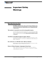
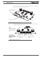
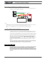
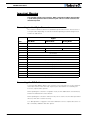
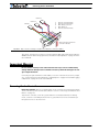
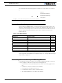
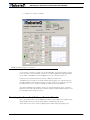
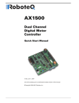
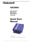
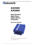
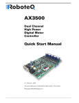
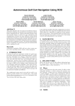
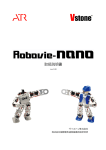
AX500
Dual Channel
Digital Motor
Controller
Quick Start Manual
v1.9b, June 1, 2007
visit www.roboteq.com to download the latest revision of this manual
©Copyright 2003-2007 Roboteq, Inc.
SECTION 1
Important Safety
Warnings
Read this Section First
The AX500 is a power electronics device. Serious damage, including fire, may
occur to the unit, motors, wiring and batteries as a result of its misuse. Please
review the User’s Manual for added precautions prior to applying full battery
or full load power.
This product is intended for use with rechargeable batteries
Unless special precautions are taken, damage to the controller and/or power supply
may occur if operated with a power supply alone. See“Power Regeneration Considerations” on page 31 of the Users Manual. Always keep the controller connected
to the Battery.
Avoid Shorts when Mounting Board against Chassis
Use precautions to avoid short circuits when mounting the board against a metallic
chassis with the heat sink on or removed. See “Attaching the Controller Directly to a
Chassis” on page 151.
Do not Connect to a RC Radio with a Battery Attached
Without proper protection, a battery attached to an RC Radio may inject its voltage
directly inside the controller’s sensitive electronics. See
Beware of Motor Runaway in Improperly Closed Loop
Wiring or polarity errors between the feedback device and motor in position or
closed loop position mode may cause the controller to runaway with no possibility
to stop it until power is turned off.
AX500 Motor Controller User’s Manual
2
SECTION 2
AX500
Quick Start
This section will give you the basic information needed to quickly install, setup and
run your AX500 controller in a minimal configuration.
What you will need
For a minimal installation, gather the following components:
•
•
•
•
•
One AX500 Controller and its provided cables
12V to 24V battery
One or two brushed DC motors
One R/C to DB15 connector (provided)
Miscellaneous wires, connectors, fuses and switch
Locating the Connectors
Take a moment to familiarize yourself with the controller’s connectors.
AX500 Motor Controller User’s Manual
3
AX500 Quick Start
The front side contains the 15-pin connector to the R/C radio, joystick or microcomputer, as
well as connections to optional switches and sensors.
Connector to Receiver/
Controls and sensors
Status LED
FIGURE 1. AX500 Controller Front View
At the back of the controller (shown in the figure below) are located all the that must be
connected to the batteries and the motors.
Note:
Both VMot terminals are
connected to each other
in the board and must be
wired to the same voltage.
Power Must be connected to VCon and
VMot for the controller
to operate
VCon
VMot
M2+
M2-
Motor 2
3 x Gnd
M1-
M1+ VMot
Motor 1
FIGURE 2. AX500 Controller Rear View
4
AX500 Motor Controller User’s Manual
Version 1.9b. June 1, 2007
Connecting to the Batteries and Motors
Connecting to the Batteries and Motors
Connection to the batteries and motors is shown in the figure below and is done by connecting wires to the controller’s terminal strip.
Motor2
+
Power on/off switch
+
Fuse
VMot
M1+
M1VCon
GND
GND
GND
M2M2+
VMot
Motor1
Controller
12V to 24V
Motor Battery
Notes:
-
The Battery Power connection are doubled in order to provide the maximum current to the controller. If
only one motor is used, only one set of motor power cables needs to be connected.
-
Typically, 1 or 2 x 12V batteries are connected in series to reach 12 or 24V respectively.
FIGURE 3. AX500 Electrical Power Wiring Diagram
1- Connect each motor to one of the two M+ and M- terminal pairs. Make sure to respect
the polarity, otherwise the motor(s) may spin in the opposite direction than expected
two of the three Ground terminals2- Connect the VCon terminal (powering the controller’s
internal circuits) through a power switch to the main battery. Connect the VMot terminals
(powering the output drivers) directly and permanently to the positive battery terminal.
VCon may be connected to a separate battery to ensure that the controller stays alive even
as the battery powering the Motors discharges. Motors will turn only if voltage is
present on both VCon and VMot. Refer to the chapter “Connecting Power and Motors to
the Controller” on page 25 for more information about batteries and other connection
options.
The two are connected to each other inside the controller. The same is true for the.
You should wire each pair together as shown in the diagram above.
Important Warning
Do not rely on cutting power to the controller for it to turn off if the Power Control is
left floating. If motors are spinning because the robot is pushed are pushed or
because of inertia, they will act as generators and will turn the controller, possibly in
an unsafe state. Always use the switch on the VCon terminal to power the controller
On or Off.
AX500 Motor Controller User’s Manual
5
AX500 Quick Start
Important Warning
The controller includes large capacitors. When connecting the Motor Power Cables,
a spark will be generated at the connection point. This is a normal occurrence and
should be expected.
Connecting to the 15-pin Connector
The controller’s I/O are located on it’s standard 15-pin D-Sub Connector. The functions of
some pins varies depending on controller model and operating mode. Pin assignment is
found in the table below.
Signal
Pin
RC Mode
RS232 Mode
Analog Mode
1
100mA Digital Output C (same as pin 9)
2
TxData
3
RC Ch1
RxData
Unused
4
RC Ch 2
Digital Input F
5
Ground Out
6
Unused
7
Unused
8
Digital Input E and Analog Input 4
9
100mA Digital Output C (same as pin 1)
10
Analog Input 2
11
Analog Input 1
12
Analog Input 3
13
Ground Out
14
+5V Out (100mA max.)
15
Emergency Stop or Invert Switch input
Connecting the R/C Radio
Connect the R/C adapter cables to the controller on one side and to two or three channels
on the R/C receiver on the other side. If present, the third channel is for activating the
accessory outputs and is optional.
When operating the controller in “Separate” mode, the wire labelled Ch1 controls Motor1,
and the wire labelled Ch2 controls Motor2.
When operating the controller in “Mixed” mode, Ch1 is used to set the robot’s speed and
direction, while Ch2 is used for steering.
See “R/C Operation” on page 81 of the User’s Manual for a more complete discussion on
R/C commands, calibration and other options.
6
AX500 Motor Controller User’s Manual
Version 1.9b. June 1, 2007
Powering On the Controller
Channel 3
Channel 2
3:
4:
6:
7:
8:
Channel 1
Channel 1 Command Pulses
Channel 2 Command Pulses
Radio battery (-) Ground
Radio battery (+)
Channel 3 Command Pulses
8
9
Pin 1
Wire loop bringing power from
controller to RC radio
15
FIGURE 4. R/C connector wiring for 3 channels and battery elimination (BEC)
This wiring - with the wire loop uncut - assumes that the R/C radio will be powered by the
AX500 controller. Other wiring options are described in “R/C Operation” on page 81 of the
User’s Manual.
Important Warning
Do not connect a battery to the radio when the wire loop is uncut. The RC battery
voltage will flow directly into the controller and cause permanent damage if its voltage is higher than 5.5V.
Connecting the optional channel 3 will enable you to turn on and off the accessory output.
See “Connecting Sensors and Actuators to Input/Outputs” on page 47 and “Data Logging
in R/C Mode” on page 91 of the User’s Manual.
Powering On the Controller
Important reminder: There is no On-Off switch on the controller. You must insert a switch
on the controller’s power terminal as described in section“Connecting to the Batteries and
Motors” on page 15.
To power the controller, center the joystick and trims on the R/C transmitter. In Analog
mode, center the command potentiomenter or joystick.Then turn on the switch that you
have placed on the on the VCon wire.
AX500 Motor Controller User’s Manual
7
AX500 Quick Start
The status LED will start flashing a pattern to indicate the mode in which the controller is
in:
RC Mode
RS232 Mode No Watchdog
RS232 Mode with Watchdog
Analog Mode
FIGURE 5. Status LED Flashing pattern during normal operation
Default Controller Configuration
Version 1.9b of the AX500 software is configured with the factory defaults shown in the
table below. Although Roboteq strives to keep the same parameters and values from one
version to the next, changes may occur from one revision to the next. Make sure that you
have the matching manual and software versions. These may be retrieved from the
Roboteq web site.
TABLE 1. AX500 Default Settings
Parameter
Default Values
Letter
Input Command mode:
(0) = R/C Radio mode
I
Motor Control mode
(0) = Separate A, B, speed control, open loop
C
Amp limit
(5) = 13.125A
A
Acceleration
(2) = medium-slow
S
Input switch function
(3) = no action
U
Joystick Deadband
(2) = 16%
d
Exponentiation on channel 1
(0) = Linear (no exponentiation)
E
Exponentiation on channel 2
(0) = Linear (no exponentiation)
F
Left / Right Adjust
(7) = no adjustment
L
Any one of the parameters listed in Table 1, and others not listed, can easily be changed
either using the PC with the Roboteq Configuration Utility. See “Using the Roborun Configuration Utility” on page 131.
Connecting the controller to your PC using Roborun
Connecting the controller to your PC is not necessary for basic R/C operation. However, it
is a very simple procedure that is useful for the following purposes:
8
•
to Read and Set the programmable parameters with a user-friendly graphical interface
•
•
•
•
to obtain the controller’s software revision and date
to send precise commands to the motors
to read and plot real-time current consumption value
Save captured parameters onto disk for later analysis
AX500 Motor Controller User’s Manual
Version 1.9b. June 1, 2007
Obtaining the Controller’s Software Revision Number
•
to update the controller’s software
FIGURE 6. Roborun Utility screen layout
To connect the controller to your PC, use the provided cable. Connect the 15-pin connector
to the controller. Connect the 9-pin connector to your PC’s available port (typically COM1) use a USB to serial adapter if needed. Apply power to the controller to turn it on.
Load your CD or download the latest revision of Roborun software from
www.Roboteq.com, install it on your PC and launch the program. The software will automatically establish communication with the controller, retrieve the software revision number and present a series of buttons and tabs to enable its various possibilities.
The intuitive Graphical User Interface will let you view and change any of the controller’s
parameters. The “Run” tab will present a number of buttons, dials and charts that are used
for operating and monitoring the motors.
Obtaining the Controller’s Software Revision Number
One of the unique features of the AX500 is the ability to easily update the controller’s operating software with new revisions downloaded from Roboteq’s web site at
www.roboteq.com. This is useful for adding features and/or improving existing ones.
AX500 Motor Controller User’s Manual
9
AX500 Quick Start
Each software version is identified with a unique number. Obtaining this number can be
done using the PC connection discussed previously.
Now that you know your controller’s software version number, you will be able to see if a
new version is available for download and installation from Roboteq’s web site and which
features have been added or improved.
Installing new software is a simple and secure procedure, fully described in “Updating the
Controller’s Software” on page 146 of the User’s Manual.
Exploring further
By following this quick-start section, you should have managed to get your controller to
operate in its basic modes within minutes of unpacking.
Each of the features mentioned thus far has numerous options which are discussed further
in the complete User’s Manual, including:
•
•
•
•
•
•
•
10
Self test mode
Emergency stop condition
Using Inputs/Outputs
Current limiting
Closed Loop Operation
Software updating
and much more
AX500 Motor Controller User’s Manual
Version 1.9b. June 1, 2007