1
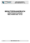
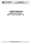
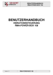
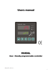
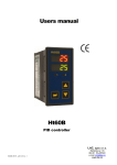
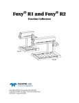
USER MANUAL
RMA-POWER-BOX 107/230
USER MANUAL
VIBRATION CONTROL
RMA-POWER-BOX 107/230
Version 2.2
RMA-POWER-BOX 107/230
1
USER MANUAL
RMA-POWER-BOX 107/230
IMPORTANT NOTES
Electrical danger within the meaning of this documentation or the warning labels on the
product itself respectively means that death, serious injury or considerable material
damage may occur if the respective measures of precaution are not taken.
Mechanical danger within the meaning of this documentation or the warning labels on the
product itself respectively means that death, serious injury or considerable material
damage may occur if the respective measures of precaution are not taken.
Disconnecting voltaged parts within the meaning of this documentation means that
before maintenance, repair and installation work, the voltage must be switched off and
secured against being switched on again.
Qualified Staff
According to this user manual and the labels on the product itself, qualified staff includes those
persons, who are familiar with the installation, mounting, initial operation and operation of the device
as well as the dangers associated with this and who have the qualifications necessary for their work,
such as:
1. Training or instruction or authorisation respectively to switch electric circuits and devices on and
off, ground and mark them according to the standards of safety engineering.
2. Training and instruction according to the standards of safety engineering concerning the care and
use of adequate safety equipment.
3. First aid training
Intended Use
The RMA-POWER-BOX 107 must only be used for the control of our KÖBRATOR – oscillating rails.
Warranty
Adherence to the user manual is the pre-condition for a failure-free operation and for the settlement of
possible claims under the warranty. Therefore, please study the user manual before you operate the
device.
Disposal
Dispose of the RMA-POWER-BOX 107 depending on composition and existing regulations as:
-steel scraps
-aluminium
-copper
-synthetic material
-electronic scraps
Version 2.2
RMA-POWER-BOX 107/230
2
USER MANUAL
RMA-POWER-BOX 107/230
Index
1. Safety Instructions ________________________________________________________________________ 4
2. Installation ______________________________________________________________________________ 5
2.1 Mechanical Installation __________________________________________________________________________ 5
2.3 Connection Diagram (Example) ___________________________________________________________________ 7
3. Technical Data ___________________________________________________________________________ 8
4. Commissioning___________________________________________________________________________ 9
5. Operation _______________________________________________________________________________ 9
5.1 Operating and display elements __________________________________________________________________ 9
5.2 Permanent displays ___________________________________________________________________________ 10
5.3 User menu __________________________________________________________________________________ 10
5.4 Main menu __________________________________________________________________________________ 11
6. Troubleshooting _________________________________________________________________________ 14
6.1 In case of a fault______________________________________________________________________________
6.2 Locating the fault ____________________________________________________________________________
6.2.1 Error list __________________________________________________________________________________
6.3 Replacement of fuses __________________________________________________________________________
14
14
15
16
RMA-POWER-BOX 107/230
3
Version 2.2
USER MANUAL
RMA-POWER-BOX 107/230
1. Safety Instructions
The RMA-POWER-BOX-107 carries dangerous voltage which can cause severe or fatal
injuries.
The RMA-POWER-BOX-107 controls oscillating mechanical parts
(KÖBRATOR), which may be dangerous.
Safety measures and safety devices must correspond with the valid national regulations
(e.g. VDE 0100 T410 /VDE 0113 T1 or EN 60204 / VDE 0160 respectively)
Necessary safety measure: grounding of the RMA-POWER-BOX-107
Necessary safety device:
line safety switch (fuse is integrated)
If you do not wish to install the device immediately, but instead wish to store it:
The storage place must be dry and clean;
the storage temperature must be between –25°C and + 85°C.
Check the device immediately for damaged packaging. Send complaints concerning
damages immediately.
See to it that damaged products are not operated!
The connection, initial operation, as well as maintenance and repair work must only be
executed by qualified expert staff, taking into consideration this manual and all other
connection diagrams belonging to the RMA-POWER-BOX 107 and the presently valid
national /international regulations (safety / accident prevention)
The RMA-POWER-BOX 107 is built for 115V or 230V operation. However, the voltage must
be pre-set by the voltage selector switch inside the box. An incorrectly set switch can
lead to the failure of the RMA-POWER-BOX!
We reserve the right to change technical data and constructions beneficial to technical
progress.
Version 2.2
RMA-POWER-BOX 107/230
4
USER MANUAL
RMA-POWER-BOX 107/230
2. Installation
2.1 Mechanical Installation
Should the RMA-POWER-BOX 107 have already been mounted by KÖBERLEIN, please
disregard Chapter 2.1.
When opening the cover, voltaged parts are uncovered.
When closing the cover, live lines can be pinched.
There is danger of pinching when opening and closing the cover.
MAKE SURE the voltage of the RMA-POWER-BOX-107 is disconnected before opening the
cover.
If the box is delivered loose, mount it through the intended mounting holes. The distance
between the vibration control and the KÖBRATOR should not exceed 10 meters. In order
to access the mounting holes, the cover of the RMA-POWER-BOX 107 must be opened by
removing the four bolts.
Loosen the four mounting bolts of the cover as shown.
Place cover near casing.
WARNING: Do not shear off any cables.
Now the mounting holes of the casing are accessible.
The drill hole distance is:
Horizontal: 125mm
Vertical:
112,5mm
Mounting bolts: max.: M4
Version 2.2
RMA-POWER-BOX 107/230
5
USER MANUAL
RMA-POWER-BOX 107/230
2.2 Electrical Installation
Please be sure to note the safety instructions in Chapter 1 during the electrical installation!
THE DEVICE MUST BE GROUNDED.
Please be sure to note the safety instructions in Chapter 1 during the electrical
installation!
BE SURE to disconnect the voltage of the RMA-POWER-BOX-107 before the connection
and disconnection of the mains connector plug.
The mains supply line must be 1,5mm² or 2,5mm² (limited by the plug on the underside of
the BOX). Make sure you pay attention to the voltage drop in case of longer lines! Only the
delivered cable may be used as a connecting line for the KÖBRATOR. Only one
KÖBRATOR may be operated at the output of the device!
Connect all electric connections according to the connection diagram (Example see Chapter
2.3)
Plug 1:
Connection of the mains supply line
(plug included in the scope of delivery)
Plug 2:
Connection of control, contact operative/ malfunction
M12 connection plug
Plug 3:
Connection of control, Reset malfunction (+ alternatively vibration on)
M12 connection plug
Plug 4:
Connection of control, vibration on
M12 connection plug
Plug 5:
Connection of KÖBRATOR magnet
(plug and line included in the scope of delivery)
Version 2.2
RMA-POWER-BOX 107/230
6
USER MANUAL
RMA-POWER-BOX 107/230
2.3 Connection Diagram (Example)
Version 2.2
RMA-POWER-BOX 107/230
7
USER MANUAL
RMA-POWER-BOX 107/230
3. Technical Data
Frequency:
115 / 230V +/- 10% (must be set with
the switch!)
50 .... 60Hz
Power consumption:
max.60VA
Recommended Pre-fusing:
2 A / characteristic line C
Operating Voltage:
Magnet – Output:
15Vss ... 30Vss
10.00Hz ... 99.99 Hz
0.01Hz
50VA
overcurrent, short circuit,
derating, open circuit
adjustable output voltage
adjustable output frequency:
smallest frequency interval:
maximum connecting power:
Disconnection in case of:
Inputs:
Input „vibration on“:
current consumption at 24V DC:
approx. 7mA
Input „Reset“:
current consumption at 24V DC:
approx. 7mA
Relay output floating:
Maximum contact load
30V DC
0.5A
Operating ambient temperature:
Storage:
Measurements:
WxHxD
0 ... 50°C
-25 ... 85°C
140x180x72mm
EMV - Test
According to
EN55011
EN61000-3-3 (system perturbation)
Protection class:
Ι (grounded)
Protection type:
IP65 (with screwed connecting lines)
Version 2.2
RMA-POWER-BOX 107/230
8
USER MANUAL
RMA-POWER-BOX 107/230
4. Commissioning
Before commissioning, the safety instructions in Chapter 1 regarding the dangers of
electrical systems must be observed.
Before commissioning, the safety instructions in Chapter 1 regarding the dangers of
mechanical systems must be observed.
When installation has been concluded, as described in Chapter 2, commissioning can be started.
Switch on the supply voltage to the RMA-POWER-BOX 107. The display now shows the Program
Version No. for 5 seconds. Subsequently, the RMA-POWER-BOX 107 signals that it is ready for
operation via Plug 2. After power-up, the Auto Mode is always active. The input "Vibration ON"
(Plug 4) can be used to switch the magnet on/off, e.g. by means of a PLC. With the magnet
switched off, the display shows "A 0". With the magnet switched on, the display shows the preset
vibration value, e.g. "A 87".
5. Operation
5.1 Operating and display elements
LED "MAGNET" (green)
Display
LED "Uin" (green)
LED "ERROR" (red)
ENTER key
MODE key
Key > increases
the value
Key < decreases
the value
Briefly pressing the keys < or > decreases/increases the corresponding parameter in small steps.
Holding the keys < or > down starts the fast mode, which permits rapid changing of the setting.
The adjusted values must be stored by pressing the ENTER key. Pressing the MODE key takes
you to the next operating mode or to the next adjustment parameter.
Version 2.2
RMA-POWER-BOX 107/230
9
USER MANUAL
RMA-POWER-BOX 107/230
5.2 Permanent displays
The LED "Uin" lights up as soon as the supply voltage is connected to the unit.
The LED "MAGNET" blinks with the preset magnet output frequency as soon as the output is
active.
The LED "ERROR" lights up as soon as the unit detects a fault (for details, see Chapter 6.
Troubleshooting).
5.3 User menu
Display
Description
Value / function
Display of the Program Version 2.2
Only display
Indication of an error or fault (for details, see
Chapter 6. Troubleshooting).
Automatic Mode – (normal operating mode) the
selected vibration power is shown.
Automatic Mode disabled – the key lock is active.
Operation as in Automatic Mode.
Only display
Hand Mode – here, the vibration power for
automatic operation can be changed.
Basic Mode
ENTER
Pressing
for 10 sec.
toggles the key lock on/off.
0...100%
ENTER
Pressing the following key combination takes you
back to the Main menu.
Hold down
Only display 0...100%
and press
ENTER
Pressing
stores the
vibration output value
adjusted under "u" in the
Main menu.
three times.
5.3.1 AUTO Mode
In the Auto Mode, the magnet can only be operated via the input "Vibration ON" (Plug 4).
With the magnet switched off, the display shows "A 0". With the magnet switched on, the
display shows the preset vibration value, e.g. "A 87". The output power cannot be changed in
this operating mode.
The key lock can only be activated in the Auto Mode by pressing the ENTER key for 10 sec.
The display shows AL ( => AUTO LOCK).
To deactivate the key lock, simply press the ENTER key again for 10 sec.
Version 2.2
RMA-POWER-BOX 107/230
10
USER MANUAL
RMA-POWER-BOX 107/230
5.3.2 HAND Mode
In the Hand Mode, the output power for the magnet is permanently on. The display shows the
currently selected value (e.g. H 87). By pressing the keys < or > it is possible to change the
vibration power. Pressing the ENTER key stores the changed value for the Auto Mode (the
value is maintained also in case of a power failure). If no key is pressed during 1 minute, the
unit automatically switches back into the Auto Mode.
5.3.3 BASIC Mode
Also in the Basic Mode, the output power for the magnet is permanently on. The display shows
the currently active output value (e.g. G 87).
Pressing the ENTER key transfers the factory setting to the Auto and Hand Modes.
Access to the Main menu from the Basic Mode is via a special key combination (see table in
Chapter 5.3 User menu).
5.4 Main menu
Display
Description
Value / function
Vibration power – here, the standard factory setting 0...100%
for vibration power can be changed for automatic
operation.
Resonance frequency of the magnet.
10.00 Hz...99.99 Hz
Soft start – here, a specified time can be adjusted,
during which the unit transmits the resonant
frequency to the magnet.
Display of the unit's Serial No.
0...255%
Delay – here, a delayed switch-off for the input
"Magnet ON" can be activated.
0 = Off
1 = On
Only display
Holding down the ENTER key for 3 sec. takes you back to the User menu.
Version 2.2
RMA-POWER-BOX 107/230
11
USER MANUAL
RMA-POWER-BOX 107/230
5.4.1 Parameter "u" – Vibration power
This parameter has been preset to an optimum value (e.g. 60) at the factory. The value is
stored for all Modes.
If the operator has changed the vibration power value in Mode "H" (e.g. to 87), Modes "A" and
"H" can be reset to the original factory setting (stored in Parameter "u", e.g. 60) by means of
the Basic Mode "G".
The setting in Mode "H" has priority.
5.4.2 Parameter "F" – Frequency
This parameter is used to preset the magnet voltage frequency. Every unit has been preset at
the factory with the specific frequency of the KÖBRATOR. However, the resonance of the
overall system depends on various factors. Therefore, it might be necessary to do some fine
tuning after the system has been installed.
Proceed as follows for fine tuning:
Set Parameter "u" to 100%, and store by pressing ENTER. Change to parameter "F", and use
key ">" or "<" to adjust the maximum vibration amplitude. Store this setting by pressing the
ENTER key. Now change back to Parameter "u", and adjust the optimum vibration power for
the component. Press ENTER to store the value. Now hold down the ENTER key until the
display changes to Mode "G" (Basic Mode) in the User menu. Pressing the ENTER key again
will transfer the value adjusted in "u" into the Modes "A" and "H".
5.4.3 Parameter "S" – Soft start
Parameter "S" enables a delay time to be adjusted, during which the unit transmits the
resonance frequency to the magnet. This delay prevents the magnet "bottoming" on the yoke
during start-up.
5.4.4 Parameter "d" – Delay
Parameter "d" – causes the magnet to be switched off only after a delay (=1) time has elapsed.
This might be necessary e.g. with timed outputs of safety control systems, to prevent
inadvertent operation of the magnet output.
Version 2.2
RMA-POWER-BOX 107/230
12
USER MANUAL
RMA-POWER-BOX 107/230
5.5 Menu structure
START
10sec.
ENTER
MODE
ENTER
MODE
ENTER
MODE
&
&
ENTER
ENTER ENTER
ENTER
MODE
ENTER
MODE
ENTER
MODE
MODE
ENTER
MODE
3sec. ENTER
Version 2.2
RMA-POWER-BOX 107/230
13
USER MANUAL
RMA-POWER-BOX 107/230
6. Troubleshooting
6.1 In case of a fault
The following applies for all operating modes:
Should a malfunction occur with the magnet (open or short circuit), the display changes to
ERROR, and the unit switches into the Fault Mode. The magnet output (Plug 5) is switched off,
and the potential-free relay (Plug 2) is de-energized. Evaluation of the malfunction is possible via
pins 1, 2, and 4.
Together with the ERROR display, the red "ERROR" LED lights up.
The malfunction can be acknowledged either by pressing the ENTER key, or by means of the
input "Fault reset" (Plug 3). Subsequently, the RMA changes back into the Auto Mode.
6.2 Locating the fault
This chapter on troubleshooting only covers the components of the RMA-POWER-BOX 107 in
connection with a KÖBRATOR.
Troubleshooting only by qualified staff!
Troubleshooting only by qualified staff!
BE SURE to disconnect the voltage of the RMA-POWER-BOX-107 before opening the
cover.
Version 2.2
RMA-POWER-BOX 107/230
14
USER MANUAL
RMA-POWER-BOX 107/230
6.2.1 Error list
Malfunction
Cause
Solution
There is supply voltage, but
there is no display
Fuse defect
Replace fuse by expert staff
(see Chapter 7.2)
The output MAGNET is
selected, however, no
vibration can be determined
in the KÖBRATOR
KÖBRATOR is jammed
mechanically
Turn off device and determine
whether KÖBRATOR is
jammed
or
Distance between yoke and
magnet in the KÖBRATOR has
changed
Display ERROR
Version 2.2
Please contact the service
technicians in our company in
the manufacturing department
"Elektro” in order to find out the
set interval between the yoke
and the magnet.
Electric connection between
KÖBRATOR and RMA 107 is
interrupted
or
Control plug-in connection on
the back of the KÖBRATOR.
Determine resistance of the
magnet in the KÖBRATOR,
possibly replace magnet.
Magnet in the KÖBRATOR
defect
(Please consult the KÖBRATOR
maintenance manual and spare parts
list for the magnet resistance.)
RMA-POWER-BOX 107/230
15
USER MANUAL
RMA-POWER-BOX 107/230
6.3 Replacement of fuses
When opening the cover, live parts are uncovered.
When closing the cover, live lines can be pinched.
There is danger of pinching when opening and closing the cover.
MAKE SURE the voltage of the RMA-POWER-BOX-107 is disconnected before opening the
cover.
Disconnect the voltage of the RMA-POWER-BOX 107
and secure it against being switched on again.
Open the four mounting bolts of the cover
as shown.
.
Version 2.2
RMA-POWER-BOX 107/230
16
USER MANUAL
RMA-POWER-BOX 107/230
Place cover near casing.
WARNING: do not shear off any cables
Now the mounting holes of the casing are
accessible
Remove defective fuses and replace with new
fuses. (I=4A T)
Close cover and re-initiate operation of the device.
Version 2.2
RMA-POWER-BOX 107/230
17