1
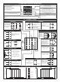
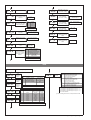
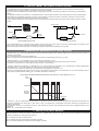
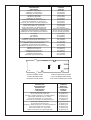
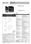
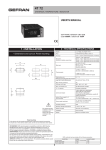
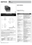
800 V
VALVE CONTROLLER
USER’S MANUAL
SOFTWARE VERSION 3.2x
code 80210C / Edition 12 - 03/08
2 • TECHNICAL SPECIFICATIONS
1 • INSTALLATION
• Dimensions and cut-out; panel mounting
63
2 x 4 digits, green, height 10 and 7mm
4 mechanical keys (Man/Auto, INC, DEC, F)
0.2% full scale at 25°C room temperature
Main input
TC, RTD (Pt100 - JPT100), PTC,
50mV Ri ≥ 1MΩ; 10V Ri ≥ 10KΩ; 20mA, Ri = 50Ω
Thermocouples
IEC 584-1
(J, K, R, S, T, B, E, N, Ni-Ni18Mo, L NiCr-CuNi)
Cold junction error
0,1° / °C
RTD type (scale configurable within indicated
DIN 43760 (Pt100, JPT100)
range, with or without decimal point)
70
48
Display
Keys
Accuracy
PTC type (on request)
990Ω, 25°C
Max line resistance for RTD
°C / °F selection
20Ω
detection of short-circuit or opening of probes, LBA
alarm, HB alarm
configurable from faceplate
Linear scale ranges
-1999 to 9999 with configurable decimal point position
Controls
pb / dt / di
Action
Control outputs
Cycle time
Main output type
Softstart
Maximum power limit heat / cool
Fault power setting
Automatic blanking
PID, Self-tuning, on-off
0.0 ... 999.9% / 0.00 ... 99.99min / 0.00 ... 99.99min
Heat / Cool
on / off, pwm, Open / Close
0.1 ... 200 sec
Relay, Logic, Continuous (optional)
0.0 ... 500.0 min
0.0 ... 100.0 %
-100.0 ... 100.0 %
Optional exclusion, displays PV value
Configurable alarms
3 configurable alarms type: max, min, symmetrical,
absolute or relative, LBA, HB
Alarm masking
- exclusion during warm up
- latching reset from faceplate or external contact
Type of relay contact
Logic output for static relays
NO (NC), 5A, 250V, cosϕ = 1
11Vdc, Rout = 220Ω (6V/20mA)
(option) remote Setpoint
or Amperometric input
Feedback input
Potentiometer valve position
0 ... 10V, 2 ... 10V, Ri ≥ 1MΩ
0 ... 20mA, 4 ... 20mA, Ri = 5Ω
Potentiometer > 500Ω,
TA 50mAac, 50/60Hz, Ri = 1,5Ω, isolation 1500V
CT scale range
configurable from 0, ... , 100.0A
Transmitter power supply (optional)
filtered 10 / 24Vdc, max 30mA
short-circuit protection, isolation 1500V
48
Safety
70
45
45
129
10
!
For correct and safe
installation, follow the
instructions and
observe the warnings
contained in this manual
Panel mounting:
To fix the unit, insert the brackets provided into the seats on either side of the
case. To mount two or more units side by side, respect the cut-out dimensions
shown in the drawing.
CE MARKING: EMC conformity (electromagnetic compatibility) with EEC Directive
89/336/CEE with reference to the generic Standard EN61000-6-2 (immunity in
industrial environments) and EN50081-1 (emission in residential environments).
BT (low voltage) conformity respecting the Directive 73/23/CEE modified by the
Directive 93/68.
MAINTENANCE: Repairs must be done only by trained and specialized personnel.
Cut power to the device before accessing internal parts.
Do not clean the case with hydrocarbon-based solvents (Petrol, Trichlorethylene, etc.).
Use of these solvents can reduce the mechanical reliability of the device. Use a cloth
dampened in ethyl alcohol or water to clean the external plastic case.
SERVICE: GEFRAN has a service department. The warranty excludes defects caused
by any use not conforming to these instructions.
80210C_MHW_800V_0308_ENG
Analogue retransmission signal (opt)
10V / 20mA, isolation 1500V
Logic inputs (optional)
24V NPN, 4.5mA; 24V PNP, 3.6mA
isolation 1500V
Serial interface (optional)
Baud rate
Protocol
CL; RS422/485; RS232; isolation 1500V
1200 ... 19200
GEFRAN / MODBUS
Power supply (switching type)
(std) 100 ... 240Vac/dc ±10%; 50/60Hz, 12VA max
(opt.) 20...27Vac/dc ±10%; 50/60Hz, 12VA max
Faceplate protection
Working / Storage temperature range
IP65
0...50°C / -20...70°C
Relative humidity
20 ... 85% non-condensing
Environmental conditions of use
for internal use only, altitude up to 2000m
Installation
Weight
Panel, plug-in from front
210g (complete version)
EMC conformity has been tested with the following connections
FUNCTION
Power supply cable
Relay output cable
Digital communication wires
C.T. connection cable
TC input
Pt100 input
CABLE TYPE
1 mm2
1 mm2
0,35 mm2
1,5 mm2
0,8 mm2 compensated
1 mm2
LENGTH
1m
3,5 m
3,5 m
3,5 m
5m
3m
1
3 • DESCRIPTION OF FACEPLATE
Function indicator
Indicates modes of operation
MAN = OFF (Automatic control)
MAN = ON (Manual control)
AUX = OFF (IN1 = OFF - local Setpoint 1)
AUX = ON (IN1 = ON – local Setpoint 2)
REM = OFF (local Setpoint)
REM = ON (remote Setpoint)
Indication of output states
OUT 1 (Open); OUT 2 (Close);
OUT 3 (AL 1); OUT 4 (AL 2)
PV Display: Indication of process variable
Error Indication: LO, HI, Sbr, Err
LO= the value of process variable is < di LO_S
HI= the value of process variable is > di HI_S
Sbr= faulty sensor or input values higher than max. limits
Err= PT100 third wire opened for PT100, PTC or input values
lower than min. limits (i.e.: TC wrong connection)
SV display: Indication of setpoint
Automatic/Manual adjustment selection:
Active only when PV display visualises the process variable
Function key
Gives access to the various configuration phases •• Confirms
change of set parameters and browses next or previous parameter
(if Auto/Man key is pressed)
“Raise” and “Lower” key
Press to increment (decrement) any numerical parameter •• Increment (decrement) speed is proportional to time key stays pressed ••
The operation is not cyclic: once the maximum (minimum) value of a field is reached, the value will not change even if the key remains
pressed.
4 • CONNECTIONS
• Serial line
Configurable serial
line isolated to 1500V
Passive current loop
(max. 1200 baud)
18
RS422/485 or RS232
(optional)
16
17
15
Tx
+
Rx
+
• Outputs
A (Data +)
B (Data -)
Out4 (AL2)
(W1)
GND
8
+
Rx
RS485 2-wires
7
-
Tx
User configurable
generic output
RS232
User configurable
generic output
• Outputs
Out2
(Close)
+
19
Out1
(Open)
+
21
20
PWR
~
24
- 5A/250Vac relay, cosϕ = 1
- 11Vdc logic, Rout = 220Ω
(6V/20mA)
11
- ~ 14
Pot
+
~ 13
Use wires of
adequate
diameter
(min. 1mm2)
PT100,
JPT100, PTC
TOP
18
19
17
8
5
21
16
9
4
Optional:
20...27Vac/Vdc
22
15
10
3
50/60Hz
23
14
11
2
!
12
13
24
2
+Vt
12
2
T
1
T
1
• TC
2
1
-
+
• Linear (V)
Linear input in dc voltage
0...50mV, 10...50mV,
0...10V, 2...10V
1
Current transformer
50mAac, 1,5Ω, 50/60Hz
2
-
1
+
• Linear (I)
4
Remote setpoint
0...20, 4...20mA, 5Ω
0...1V, 0...10V, R > 1MΩ
Linear input in dc current
0...20mA, 4...20mA
12
11
• Pt100 3-wires
Available thermocouples:
J, K, R, S, T, B, E, N,
Ni-Ni18Mo, L NiCr-CuNi
- Observe polarities
- For extensions, use the
correct compensating cable
for the type of TC used
Auxiliary input isolated 1500V
2
-
1
+
9
IN2
10
IN1
11
COM
• Digital inputs / Out 5
Out 5 analogue (W2)
(alternative to IN2 digital
input)
• Transmitter supply
GND
+
3
Potentiometer > 500Ω
+ Vt
5
3
6
7
20
Standard:
100...240Vac/Vdc
• Auxiliary input
GND
Out3 (AL1)
• Pt100 2-wires or PTC
• Power Supply
23
-
• Inputs
User configurable generic
output
22
~
6
- 5A/250Vac relay, cosϕ=1 - 5A/250Vac relay, cosϕ=1
- 11Vdc logic,
Rout = 220Ω (6V/20mA) - 11Vdc logic,
Rout = 220Ω (6V/20mA)
- analogue output
isolated to 1500V
(0...10V, 0...20/4...20mA)
Transmitter supply isolated
1500V
(*) terminal 11 if Out 4 is
Relay or Logic
10/24Vdc, max. 30mA shortcircuit protection
9
Digital inputs
isolated to 1500V
- NPN 24V, 4,5mA
- PNP 24V, 3,6mA
(12V, 3,6mA)
+
COM (*)
7
(IN2 alternative Out 5)
5 • RECOMMENDED WIRING LAYOUT
Low level signals
D
2
B A
Line voltage
A
Inputs
B
Serial
C
Relay outputs
D
Power supply
E
Logic/Analogue
outputs
Low level signals
E
Cable Channel
Cable Channel
Cable Channel
C
Cable Channel
Line voltage and outputs
D
B A
80210C_MHW_800V_0308_ENG
Device structure: identification of boards
CPU BOARD
DISPLAY BOARD
POWER SUPPLY
BOARD
W BOARD
SERIAL BOARD
5 • PROGRAMMING and CONFIGURATION
LEVEL 1 MENU
P.V. / S.V.
-SP-
Process variable (PV display)
Work Setpoint (SV display) or control
output value with regulator in manual
F
INFO
Information display
Press for
approx.
2 sec
dAtA
Custom menu
CFG
Control parameters
SEr
Serial communications
InP
Input settings
Out
Output settings
Local Setpoint
1
- sp.i
- sp.2
Setpoint 1
212
Setpoint 2
213
- sp.3
- sp.4
Setpoint 3
NO
S3 = ON
214
PASS
215
-- ts
inp.2
Keep the F key
pressed to scroll
the menus
YES
Setpoint 4
Limit value of timer
0 ... 9999 sec
NO
217
Amperometric input or remote
Setpoint or valve position value (with
auxiliary input enabled)
Password
Release the F key
to select the
displayed menu
PASS = 99
Press the F key to
access the
parameters
YES
(*)
2
Prot
Protection code
Hrd
Hardware configuration
Lin
Input linearization
-al.1
Alarm point 1 (scale points)
-al.2
Alarm point 2 (scale points)
-al.3
Alarm point 3 (scale points)
CuSt
“dAtA” menu setting
al.xb
Heater break alarm point (scale
points of ammeter input)
U.CAL
User calibration
0vt.p
Control output value
(+Heat / -Cool)
3
Keep the F key
pressed to exit any
menu
Keep F + Auto/Man
keys pressed for 2
sec. on any menu
to go immediately
to level 1 display
4
5
6
(*)
7
(*) The automatic return PV/SV display is disabled for these displays
NO
S4 = ON
YES
_CAL
Select calibration menu [ 0...12 ]
If Inc, Dec, F keys are not pressed within 30 sec, display returns automatically to PV/SV value.
All INFO and dAtA data on config menu remain displayed and are not timed
N.B.: Once a particular configuration is entered, all unnecessary parameters are no longer displayed
80210C_MHW_800V_0308_ENG
3
• InFo Display
INFO
Information
display
(ODE
Serial
communication
code
prot
Software
protection code
er.nr
Self
diagnostic
error code
8
Software
version
12
0
1
2
3
4
No Error
Lo
Hi
ERR
SBR
10
Manual reset
-999 ... 999
scale points
Reset power
-100.0 ... 100.0%
Antireset
0 ... 9999
scale points
Feedforward
-100.0 ... 100.0%
25
11
9
updt
-rst
p.rst
26
a.rst
27
• CFG
CFG
s.tvn
15
h-pb
-ffd
28
Control parameters
Enabling selftuning,
autotuning,
softstart
S.tun Continuous
autotuning
0
NO
1
YES
2
NO
3
YES
4
NO
5
YES
6
7
8
WAIT
9
GO
10
WAIT
11
GO
12
WAIT
13
GO
Proportional band for
heating or hysteresis on
ON-OFF action
Self-tuning
Softstart
NO
NO
YES
YES
NO
NO
NO
NO
YES
YES
NO
NO
NO
NO
NO
NO
YES
YES
NO
NO
NO
NO
YES
YES
soft
Softstart time
0.0 ... 500.0 min
xys.i
Alarm 1 hysteresis
± 999
scale points
Alarm 2 hysteresis
± 999
scale points
xys.3
Alarm 3 hysteresis
± 999
scale points
xb-t
Waiting time for HB alarm
intervention
0…999 seconds
29
30
xys.2
31
0.0 … 999.9%
full scale
16
(Value has to be higher than cycle time value of
output to which HB alarm is assigned)
33
h -it
Integral time for heating
0.00 ... 99.99 min
lba.t
17
h-dt
Derivative time for
heating
h.p.xi
Maximum power limit for
heating
0.00 ... 99.99 min
0.0 ... 100.0%
h.p.lo
254
-
(.med
97
Minimum power limit for
heating (not available for
double heat/cool action)
0
1
2
-100.0 ... 100.0%
ON / OFF
Power output in fault condition
(when probe is faulty)
0.0...999.9 digit/min.
(digit / sec see SP.ty)
Set gradient
(see applicable note)
Air
Oil
Water
0 ... 2
-atRelative gain (Rg)
(see applicable note)
1
0,8
0,4
± 25.0% f. s.
Proportional band for
cooling or hysteresis for
ON/OFF control
0 ... 999.9% f. s.
0 ... 2000 sec
207
t-lo
t- xi
Impulse min. time/actuator travel time
(useful to avoid excessive valve activity)
0.0 ... 25.0%
Impulsive intervention threshold
as percentage of valve
opening time
0.0 ... 100.0%
209
-db210
Integral time for cooling
Actuator travel time (time employed by
the valve to change from entirely open
to entirely closed)
208
Setpoint for cooling
relative to heating
setpoint
21
c-it
(*)
36
gr.sp
20
c- pb
-100.0 ... 100.0%
ON / OFF
Power limit for LBA alarm condition
216
Cooling medium
C.MEd
c.sp.o
0.0 ... 100.0%
(*)
35
Fa(.p
19
0.0 ... 500.0 min
(Set to “0” to disable LBA alarm)
34
lba.p
18
Waiting time for LBA alarm intervention
0.00 ... 99.99 min
Dead zone which can be set as a
percentage of the bottom of scale,
symmetrical with respect to the set point (if
the variable is within this band the valve is
immobile and the integral action is blocked)
Only for control of valve type V0, V1, V2
(*) LBA alarm may be reset by simultaneously pressing ∆
switching to Manual.
22
c- dt
Derivative time for
cooling
0.00 ... 99.99 min
c.p.xi
Maximum power limit for
cooling
0.0 ... 100.0%
23
+∇
0.0 ... 25.0% f.s.
keys when OutP is displayed or by
Note:
h_Pb, h_it, h_dt, h.P.Hi, hPLo, c_Pb, c_it, c_dt, c.P.Hi, c.P.Lo parameters are “read only” if the option
“control parameter groups” has been selected (showing current values)
c_Pb, c_it, c_dt parameters are “read only” if the option “relative gain heat/cool control” (Ctrl = 14) has
been selected.
24
c.p.lo
255
4
Minimum power limit
for cooling (not available
for heating/cooling
double action)
0.0 ... 100.0%
80210C_MHW_800V_0308_ENG
• Ser
Ser
Serial communications
bavd
(ode
Unit identification code for serial
communication (if enabled)
[see “hrd.1” in Hrd]
40
bAud
0
1
2
3
4
0 ... 9999
38
ser.p
Serial interface
protocol CENCAL,
MODBUS
Select Baudrate
SEr.P Serial protocol
0
CENCAL GEFRAN
1
MODBUS RTU
Baudrate
1200
2400
4800
9600
19200
CENCAL Interface
485 / 232
485 / 232
485 / 232
485 / 232
485 / 232
MODBUS Interface
485
485
485
485
485
39
- par
PAr
0
1
2
Parity selection
Parity
No parity
Odd
Even
101
• InP
InP
Input settings
SP.tY Type of remote setpoint
sp.ty
44
Setpoint type: LOC/REM,
Select type of remote
setpoint [0...3]
0
1
analogue (InP.2)
analogue (InP.2)
2
digital
(from serial line)
digital
(from serial line)
3
Absolute
Relative
absolute
relative to
local setpoint
absolute
relative to
local setpoint
+4 set gradient in digit / sec
type
Probe type, signal, enable custom linearization,
and main input scale
45
PROBE: TC (SEnS=0)
tYPE
Probe type
0
1
2
3
4
5
6
7
8
9
10
11
12
13
14
15
16
17
18
19
20
21
J (Fe-CuNi)
J (Fe-CuNi)
K (NiCr-Ni)
K (NiCr-Ni)
R (Pt13Rh - Pt)
R (Pt13Rh - Pt)
S (Pt10Rh - Pt)
S (Pt10Rh - Pt)
T (Cu-CuNi)
T (Cu-CuNi)
B (Pt30Rh - Pt6Rh)
B (Pt30Rh - Pt6Rh)
E (NiCr-CuNi)
E (NiCr-CuNi)
N (NiCrSi-NiSi)
N (NiCrSi-NiSi)
(Ni - Ni18Mo)
(Ni - Ni18Mo)
L - GOST (NiCr-CuNi)
L - GOST (NiCr-CuNi)
TC
TC
Scale
(C/F)
C
F
C
F
C
F
C
F
C
F
C
F
C
F
C
F
C
F
C
F
C
F
Scale range max.
without decimal point
0 / 1000
32 / 1832
0 / 1300
32 / 2372
0 / 1750
32 / 3182
0 / 1750
32 / 3182
-200 / 400
-328 / 752
44 / 1800
111 / 3272
-100 / 750
-148 / 1382
0 / 1300
32 / 2372
0 / 1100
32 / 2012
0 / 600
32 / 1112
Custom scale
Custom scale
Scale range max.
with decimal point
0.0 / 999.9
32.0 / 999.9
0.0 / 999.9
32.0 / 999.9
Not available
Not available
Not available
Not available
-199.9 / 400.0
-199.9 / 752.0
Not available
Not available
-100.0 / 750.0
-148.0 / 999.9
0.0 / 999.9
32.0 / 999.9
0.0 / 999.9
32.0 / 999.9
0.0 / 600.0
32.0 / 999.9
(*)
(*)
PROBE: CURRENT 20mA or TRANSMITTER (SEnS=4)
tYPE
0
1
2
3
Signal type
0...20mA
0...20mA
4...20mA
4...20mA
Scale
linear
custom linear
linear
custom linear
Scale range max.
-1999 / 9999
see table 32 values in Lin
-1999 / 9999
see table 32 values in Lin
PROBE: VOLTAGE 10V or TRANSMITTER (SEnS=5)
tYPE
0
1
2
3
Signal type
0...10V
0...10V
2...10V
2...10V
Scale
linear
custom linear
linear
custom linear
Scale range max.
-1999 / 9999
see table 32 values in Lin
-1999 / 9999
see table 32 values in Lin
PROBE: CUSTOM 10V (SEnS=6)
tYPE
0
Signal type
Custom 0...10V
Scale
linear
1
Custom 0...10V
custom linear
Scale range max.
-1999 / 9999
see table 32 values
in Lin
PROBE: CUSTOM 50mV, 20mA (SEnS=7)
PROBE: RTD 3 wires (SEnS=1)
tYPE
0
1
2
3
4
5
Probe type
Scale
(C/F)
PT100
C
PT100
F
JPT100 (JIS C 1609/81)
C
JPT100 (JIS C 1609/81)
F
RTD
C
RTD
F
PROBE: PTC (SEnS=2)
tYPE
Probe type
0
1
2
3
PTC 990Ω
PTC 990Ω
PTC 990Ω
PTC 990Ω
Scale range max.
without decimal point
-200 / 850
-328 / 1562
-200 / 600
-328 / 1112
Custom scale
scala custom
Scale range max.
with decimal point
-199.9 / 850.0
-199.9 / 999.9
-199.9 / 600.0
-199.9 / 999.9
(*)
(*)
tYPE
0
1
Signal type
Custom
Custom
Scale
linear
custom linear
Scale range max.
-1999 / 9999
see table 32 values
in Lin
(*) Linearization and scale limit settings (with or without decimal point) are
selectable from PC via serial line
on request, instead of RTD 3 wires
Scale
(C/F)
C
F
C
F
Scale range max.
without decimal point
-55 ... 120
-67 ... 248
Custom scale
Custom scale
Scale range max.
with decimal point
-55.0 ... 120.0
-67.0 ... 248.0
(*)
(*)
PROBE: VOLTAGE 50mV (SEnS=3)
tYPE
0
1
2
3
Signal type
0...50mV
0...50mV
10...50mV
10...50mV
Scale
linear
custom linear
linear
custom linear
80210C_MHW_800V_0308_ENG
Scale range max.
-1999 / 9999
see table 32 values in Lin
-1999 / 9999
see table 32 values in Lin
5
filt
Digital filter on main input
flt.2
0.0 ... 20.0 sec
46
Digital filter on aux input
(if enabled)
[see “hrd.1” on Hrd]
0.0 ... 20.0 sec
53
fild
47
dp- s
Digital filter on display
process variable: acts as
hysteresis
lo.52
0 ... 9.9
scale points
Min…max input range
selected in tyP.2
Maximum range for aux
input (if enabled)
[see “hrd.1” on Hrd]
Min…max input range
selected in tyP.2
Offset correction of aux
input (if enabled)
[see “hrd.1” on Hrd]
-999 ... 999
scale points
lo-l
Lower limit for local
setpoint and absolute
alarms
Lo.S ... Hi.S
xi-l
Upper limit for local
setpoint and absolute
alarms
Lo.S ... Hi.S
54
dP_S
0
1
2
3
Decimal point position for
main input scale, alarm
and remote setpoint
48
xi.52
Format
xxxx
xxx.x
xx.xx (*)
x.xxx (*)
55
of.52
(*) not available for TC,
RTD and PTC scales
lo-s
Minimum range for aux
input (if enabled)
[see “hrd.1” on Hrd]
56
Minimum limit of main
input scale
min...max input range
selected in tyPE
49
57
xi-s
Maximum limit of main
input scale
min...max input range
selected in tyPE
50
58
ofst
Offset correction of main
input
-999 ... 999
scale points
51
typ.2
52
Aux analogue input
function (if enabled)
[see “hrd.1” on Hrd]
and enable custom
limitation
tYP.2
0
1
2
3
4
5
Auxiliary input function
None
Remote setpoint
Analogue remote manual
Analogue power reset
Current transformer
input for HB
Valve position
+ 8 to select custom linearization (see
table 32 values in Lin)
• Out
Out
al.1.r
60
al.2.r
61
al.3.r
62
Output settings
Select
reference
signal for
alarm 1
xb- f
AL.1.r, AL.2.r, AL.3.r
Select
reference
signal for
alarm 2
AL.x.r
0
1
2
3
Variable to compare
PV (Process variable)
InP.2 (aux input)
SSP (active setpoint)
PV (Process variable)
Alarm setpoint
AL
AL
AL (only absolute)
InP.2
InP.2 (aux input)
Select
reference
signal for
alarm 3
+ 4 only for relative alarms, they refer to SP1
(available if multiset function enabled)
AL.1.t, AL.2.t, AL.3.t
al.1.t
Alarm
type 1
63
al.2.t
Alarm
type 2
64
al.3.t
65
6
Alarm
type 3
AL.x.t
0
1
2
3
4
5
6
7
Direct (high limit)
Inverse (low limit)
direct
inverse
direct
inverse
direct
inverse
direct
inverse
Absolute or
relative to
active setpoint
absolute
absolute
relative
relative
absolute
absolute
relative
relative
Normal
Symmetric
(window)
normal
normal
normal
normal
symmetrical
symmetrical
symmetrical
symmetrical
66
HB alarm
function
Hb_F Function description
0
Relay, logic output: alarm active
on load current level lower than
setpoint during the ON time
of the control output
1
Relay, logic output: alarm active
on load current level higher than
setpoint during the OFF
time of the control output
2
Alarm active if one of functions 0 and 1
is true (OR logic between 0 and 1) (*)
3
For continuous heating output
7
For continuous cooling output
+ 0 assigned to output Out1 (only for Hb_F= 0, 1, 2)
+ 4 assigned to output Out2 (only for Hb_F= 0, 1, 2)
+ 8 assigned to output Out3 (only for Hb_F= 0, 1, 2)
+ 12 assigned to output Out4 (only for Hb_F= 0, 1, 2)
+ 16 inverse HB alarm
(*) minimum setting is fixed at 12% of amperometric full scale
+ 8 to disable on power up until first interception
+ 16 to latch alarm
80210C_MHW_800V_0308_ENG
rl.o.1
67
rl.o.2
68
rl.o.3
69
an.o.1
Out 1
Allocation of
reference signal:
HEAT, COOL,
AL1, AL2, AL3,
repetition of
digital inputs
rL.o.x
0
1
2
3
4
Out 2
5
Allocation of
6
reference signal:
7
HEAT, COOL,
8
AL1, AL2, AL3,
9
repetition of
10
digital inputs
11
12
13
14
15
Out 3
16
Allocation of
17
reference signal: 18
HEAT, COOL,
19
AL1, AL2, AL3,
20
repetition of
21
digital inputs
78
64
70
Out 4
Allocation of
reference signal:
HEAT, COOL,
AL1, AL2, AL3,
repetition of
digital inputs
An.o.1, An.o.2
rL.o.1, rL.o.2, rL.o.3, rL.o.4
Function of main output relay/logic (OUT1)
HEAT (control output for heating)
COOL (control output for cooling)
AL1 - alarm 1
AL2 - alarm 2
AL3 - alarm 3
AL.HB - alarm HB
LBA - alarm LBA
IN1 - repetition of logic input 1
IN2 - repetition of logic input 2
OPEN valve
CLOSE valve
Repetition Timer
Repeat Set / Reset
(AL1) OR (AL2)
(AL1) OR (AL2) OR (AL3)
(AL1) AND (AL2)
(AL1) AND (AL2) AND (AL3)
(HBAL) OR (AL1)
(HBAL) OR (AL1) OR (AL2)
(HBAL) AND (AL1)
(HBAL) AND (AL1) AND (AL2)
+ 32 for inverse logic signal output
rl.o.4
Heat control output with
fast cycle time (*)
Cool control output with,
fast cycle time (*)
65
An.o.x
0
1
2
3
4
5
6
7
8
9
10
11
(*) - Fixed scale limits
- Retransmission output not available with ON/OFF control action
l.an.1
71
-(t.2
72
-(t.3
73
-(t.4
74
-rel.
75
1 ... 200 sec
(0.1 ... 20.0 sec)
Cycle time for AL1
relay or logic
output = HEAT or
COOL
1 ... 200 sec
Minimum limit of
analogue repetition
signal output 1
-100.0...100.0% for power
-1999...9999 for inputs and setpoint
Maximum limit of
analogue repetition
signal output 1
-100.0...100.0% for power
-1999...9999 for inputs and setpoint
76
x.an.1
77
(*) only for rL.o.1.; HB alarm is disabled if
associated with Out1 output
Cycle time for
MAIN relay or
logic output =
HEAT or COOL
Reference value
PV - process variable
SSP - active setpoint
SP - local setpoint
InP.2 - aux input
Deviation (SSP-PV)
HEAT
(*)
COOL
(*)
AL1 (alarm point)
AL2 (alarm point)
AL3 (alarm point)
AL.HB - (alarm point)
Value acquired from serial line
+ 16 for inverted output with respect to reference value
+ 32 for output with 2...10V, 4...20mA signal
an.o.2
81
l.an.2
- (t.1
Out W1
Assignment of signal or reference value: PV, SP,
SP-PROG, DEV+, DEV-, IN.AUX, HEAT, COOL,
AL1, AL2, AL3, serial line value
Out W2.
Assignment of signal or reference value: PV, SP,
SP-PROG, DEV+, DEV-, IN.AUX, HEAT, COOL,
AL1, AL2, AL3, serial line value
Minimum limit of
analogue repetition
signal output 2
-100.0...100.0% for power
-1999...9999 for inputs and setpoint
Maximum limit of
analogue repetition
signal output 2
-100.0...100.0% for power
-1999...9999 for inputs and setpoint
79
x.an.2
80
at.ty
Cycle time for AL2
relay or logic
output = HEAT or
COOL
1 ... 200 sec
Cycle time for AL3
relay or logic
output = HEAT or
COOL
1 ... 200 sec
_rEL.
Fault action (sets state in
case of probe fault) Alarm
outputs AL1, AL2, AL3;
Select intrinsic safety
0
1
2
3
4
5
6
7
Valves
control type
0
1
2
3
disabled
V0, V1 heating, Heat
V2 heating, Heat
V3, V4 heating, Heat
211
+4 for cooling valve, COOL
+8 valve manual control with “raise” and
“lower” keys
Alarm
1
OFF
ON
OFF
ON
OFF
ON
OFF
ON
Alarm
2
OFF
OFF
ON
ON
OFF
OFF
ON
ON
Alarm
3
OFF
OFF
OFF
OFF
ON
ON
ON
ON
Note:
1) In case of broken probe, logic state of individual alarm assumes
selected logic value without consideration of alarm type (direct or
inverse): ON = alarm active;
OFF = alarm inactive
2) Assign alarms to available outputs by entering codes rLo1, rLo2,
rLo3, rLo4.
• Prot
Prot
Protection code
42
Prot
0
1
2
3
Display
SP, InP2, alarms, OutP, INFO, DATA
SP, InP2, alarms, OutP, INFO, DATA
SP, InP2, alarms, OutP, INFO
SP
Modification
SP, alarms, DATA
SP, alarms
SP
+ 4 to disable InP, Out
+ 8 to disable CFG, Ser
+ 16 to disable SW “power-up - power down”
+ 32 disable manual power latching
+ 64 to disable manual power modification
80210C_MHW_800V_0308_ENG
7
• Hrd
Hrd
Hardware configuration
hrd.1
hrd.1
Auxiliary input
installation, digital
inputs, serial
interface.
Timer and multiset
enabling
sens
Aux
analogue
input
0
1
2
3
4
5
6
7
8
9
10
11
12
13
14
15
Logic
input 1
(IN1)
Logic
input 2
(IN2)
SEnS
0
1
2
3
4
5
6
7
Selection of
probe type for
main input
Serial
interface
x
x
x
x
x
x
x
x
x
x
x
x
x
x
x
+ 8 to enable main input curve 4 point correction
(alternative to custom linearization).
See description in “Main Input Correction
Function” section.
+16 to disable averaging filter on sampled
value (available from software release 3.05)
x
x
x
x
x
x
x
x
x
Probe type for main input
Thermocouple (TC)
Resistance Thermometer (RTD)
Thermistor (PTC)
Voltage 0...50mV / 10...50mV
Current 0...20mA / 4...20mA
Voltage 0...10V / 2...10V
Custom 10V
Custom max 50mV
x
x
x
x
x
x
x
x
Note: scale selection with “tYPE” code in InP.
sns.2
Selection of probe
type for aux input
+16 to enable the Timer function
+32 to enable the Multiset function (2SP)
+64 to enable the Multiset function (4SP)
SnS.2
0
1
2
3
4
5
6
7
hrd.2
hrd.2
Installation of
relay, logic
outputs
MAIN, AL1,
AL2, AL3,
and analogue
outputs W1,
W2
OUT 1
OUT 2
OUT 3
OUT 4
(relay, logic) (relay, logic) (relay, logic) (relay, logic)
0
1
2
3
4
5
6
7
8
9
10
11
12
13
14
15
x
x
x
x
x
x
al.nr
x
x
x
x
x
x
x
x
x
x
x
x
x
x
x
x
x
x
x
+ 16 to enable analogue output W1
+ 32 to enable analogue output W2
+ 64 to invert state of LEDs compared to state of output
hrd.3
(trl
“ * “ key and
bargraph
installation
Not available in 800
series Hrd.3 = 0
CtrL
0
1
2
3
4
5
6
7
8
9
10
11
12
13
14
Control type
[0...78]
43
Select number of
enabled alarms
x
x
x
x
x
Control type
P heat
P cool
P heat / cool
PI heat
PI cool
PI heat / cool
PID heat
PID cool
PID heat / cool
ON-OFF heat
ON-OFF cool
ON-OFF heat / cool
PID heat + ON-OFF cool
ON-OFF heat + PID cool
PID heat + cool with relative gain
(see C.MEd parameter)
Selection of derivative action sampling time:
+ 0 sample 1 sec.
+ 16 sample 2 sec.
+ 32 sample 8 sec.
+ 64 sample 240 msec.
-- r.t.
Start / Stop Timer
Reset Timer
(0 ... 15)
0
1
2
3
4
5
6
7
from enabled digital input
from AL1 ON
from AL2 ON
from AL3 ON
from ALHb ON
from serial line (address 0049H, bit 0)
from serial line (address 0049H, bit 1)
from keys
~
AL.nr
0
1
2
3
4
5
6
7
Alarm 1
disabled
enabled
disabled
enabled
disabled
enabled
disabled
enabled
Alarm 2
disabled
disabled
enabled
enabled
disabled
disabled
enabled
enabled
Alarm 3
disabled
disabled
disabled
disabled
enabled
enabled
enabled
enabled
+ 8 to enable HB alarm
+ 16 to enable LBA alarm
b u t t , b u t .2
bvtt
Function of M/A
key
bvt.2
Function of
“*” key
Not available in 800 Series
but.2 = 0
0
1
2
3
4
5
6
7
8
9
No function (key disenabled)
MAN / AUTO controller
LOC / REM
HOLD
Start / Stop selftuning
Start / Stop autotuning
Set / Reset outputs Out 1... Out 4
Alarms memory reset
SP1 / SP2 Selection
Integral contribution instantaneous
zero setting
Start / Stop Timer
(se S.S.t. = 7)
Reset Timer
(se _rt = 7)
10
11
+ 16 disable function in configuration menu
(butt)
d.i.F.1, d.i.F.2
d.1.f.1
Function of digital
input 1 (IN1)
d.1.f.2
Function of digital
input 2 (IN2)
0
1
2
3
4
5
6
7
No function (disenabled input.)
MAN / AUTO controller
LOC / REM
HOLD
Start / Stop timer
Reset timer
Software on/off
Alarms memory reset
Selection SP1 ... SP2 (2SP)
Selection SP1 ... SP4 - bit Lo
Selection SP1 ... SP4 - bit Hi
8
9
+ 16 for inverse logic input
+ 32 to force logic state 0 (OFF)
+ 48 to force logic state 1 (ON)
Note: LbA alarm is not enabled with
ON/OFF type control
-s.s.t.
TA 50mA
+8 to disable averaging filter on sampled value
(available from software release 3.05)
x
x
Signal
0 ... 1V
0.2 ... 1V
0 ... 10V
2 ... 10V
0 ... 20mA
4 ... 20mA
Potentiometer
disp
Defining SV
display function
diSP
(*) 0
(*) 1
(*) 2
(*) 3
8
+8 inverse action
(*)
Lower display (SV) function
SSP - setpoint enabled
InP.2 - aux input
Control output value
Deviation (SSP - PV)
Visualisation of current time
on PV display and tS
time on SV display
+ 4 Timer in start
+16 Autoreset enabled (Stop = program reset)
(only for _S.S.t. parameter)
8
80210C_MHW_800V_0308_ENG
led.1
Function of “MAN” LEDs: M/A, L/R, ATUN, IN1, IN2
repetition, event programmer, serial port enabled, errors present
barg
Bargraph function
Function not available in series 800
LEd.1 (MAN), LEd.2 (AUX), LEd.3 (REM)
led.2
led.3
LEd.x
0
1
2
3
4
5
6
7
8
9
10
11
12
13
14
Function
none
MAN/AUTO (ON in manual, OFF in auto)
LOC/REM (ON in remote, OFF in local)
self-tuning enabled
autotuning enabled
IN1 repetition
IN2 repetition
enable serial dialogue
HOLD on
Error present (error code <> 0)
Softstart running
SP1...SP4 - bit Lo Indication
SP1...SP4 - bit Hi Indication
START/STOP Timer
RESET Timer
+ 16 for flashing LED function
• Lin
Lin
st.00
Custom linearization for main
or aux input (*)
Step 0
Scale limits
Step 32
Scale limits
......
st.32
(*) Not available for:
enabled input correction function (SenS + 8)
TC custom input type (SenS = 0; tyPE = 20,21)
RTD custom input type (SenS = 1; tyPE = 4,5)
PTC custom input type (SEnS = 2 ; tyPE = 2, 3)
• CuSt
CuSt
xead
pa.01
Set custom “dAtA” menu
Set number of parameters
in custom menu
[ 0 ... 14 ]
Identification code for
parameter 1
......
pa.14
Identification code for
parameter 4
XXXX
The identification code is specified in this
position, under the parameter name
x
• U.CAL
U.CAL
80210C_MHW_800V_0308_ENG
User
calibration
U.CAL
1
2
3
4
5
Function
Analogue output 1
Analogue output 2
Input 1 - custom probe 10V
Input 1 - custom probe 50mV
Input 2 - potentiometer
9
6 • ADJUSTMENT WITH MOTORIZED VALVE
In an adjustment process the adjustment valve has the function of varying fuel delivery (frequently corresponding to the thermal energy
introduced into the process) in relation to the signal coming from the controller.
For this purpose it is provided with an actuator able to modify its opening value, overcoming the resistances produced by the fluid passing
inside it.
The adjustment valves vary the delivery in a modulated manner, producing finite variations in the fluid passage inner area corresponding to
finite variations of the actuator input signal, coming from the controller. The servomechanism, for example, comprises an electric motor, a
reducer and a mechanical transmission system which actions the valve.
Various auxiliary components can be present such as the mechanical and electrical safety end travels, manual actioning systems, position
location.
Desired position
SetPoint
M
Control
Motor
Actuator
Process
variable
Process
Adjustment valve
Valve position
feedback
potentiometer
Adjustment valve
CONTROL EXAMPLE FOR V0 VALVE
VALVE POSITION CONTROL
The controller determines, on the basis of the dynamics of the process, the control output for the valve corresponding to the opening of the
same in such a way so as to maintain the desired value of the process variable.
With counter-reaction valves the position is normally provided by a potentiometer assembled on the actuator.
Characteristic parameters for valves control
- Actuator time (_At_) is the time employed by the valve to pass from entirely open to entirely closed (or vice-versa), and can be set with a
resolution of one second.
It is a mechanical feature of the valve+actuator unit.
NOTE: if the actuator’s travel is mechanically limited it is necessary to proportionally reduce the _At_ value.
- Minimum impulse (t_Lo) expressed as a % of the actuator time (resolution 0.1%).
This represents the minimum variation in position due to which the actuator does not physically respond to the command.
Increasing t_Lo reduces wear on the actuator with less precision in the positioning.
- Impulsive intervention threshold (t_Hi) expressed as a % of the actuator time (resolution 0.1%) represents the position displacement
(requested position – real position) due to which the manoeuvre request becomes impulsive.
The duration of the impulses is proportional to the displacement and greater than or equal to t_Lo.
This type of modulated approach allows precise control of the feedback actioned valve, by a potentiometer or not, and is especially useful in
cases of high mechanical inertia. Setting t_Hi = 0 excludes modulation in positioning.
VALVE CONTROL WITH IMPULSIVE MODULATED APPROACH, APPLICABLE ONLY TO FUNCTIONING TYPE V0, V1, V2.
Valve
command
Displacement
Impulsive
intervention
thresholds
min. impulse
Time
- Dead zone (_db_) is a displacement band between the adjustment setpoint and the process variable within which the controller does not
supply any command to the valve (Open = OFF; Close = OFF). It is expressed as a percentage of the bottom scale and is symmetrical with
respect to the setpoint.
The dead zone is useful in an operative process to avoid straining the actuator with repeated commands and an insignificant effect on the
adjustment.
Setting _db_ = 0 the dead zone is excluded.
7 • VALVE CONTROL MODES
With the controller in manual, the setting of parameter At.ty ≥ 8 allows direct control of the valve open and close commands; the instrument
indicates the presumed or real position (for type V2).
V0 - for floating valve without potentiometer;
V1 - for floating valve with potentiometer and display of position;
V2 - for valve with feedback from potentiometer and display of position.
10
80210C_MHW_800V_0308_ENG
Models V0 and V1 have similar behaviour: every manoeuvre request greater than the minimum impulse is sent to the actuator by means of the
OPEN/CLOSE relays; every action updates the presumed position of the virtual potentiometer calculated on the basis of the actuator travel
declared time.
In this way there is always a presumed position of the valve which is compared with the position request of the controller.
Having reached a presumed extreme position (entirely open or entirely closed determined by the “virtual potentiometer”) the controller provides a
command in the same direction, in this way ensuring the real extreme position is reached.
The actuators are usually protected against the OPEN command in the entirely open position or CLOSE command in the entirely closed position.
The V2 model reads the real position of the valve by means of the auxiliary analogue input, expresses the value as a percentage (0.0 – 100.0%)
and compares it with the position requested by the controller, then sends the appropriate command to the valve. The auxiliary input of the
controller is used to obtain the valve position.
Calibration is requested to memorise the extreme position of the potentiometer, minimum and maximum.
The potentiometer is usually supplied by the controller itself.
V3 - for floating valve without display of position, PI control
V4 - for floating valve with display of position, PI control; the valve position from the potentiometer is only for viewing on the display and is not
used in the adjustment.
When the difference between the position calculated by the controller and the only proportional component exceeds the value corresponding to
the minimum impulse the controller provides an OPEN or CLOSE command of the duration of the minimum impulse itself.
At each delivery the integral component of the command is set to zero (discharge of the integral).
The frequency and duration of the impulses is correlated to the integral time (_ti_).
8 • TIMER + 2 SET POINT, TIMER FUNCTION
The timer functionality is enabled in Hrd configuration in hrd.1 parameter setting the code +16 or +48 to activate the selection of two set points.
In the case of enabling, parameters _S.S.t. (start/stop timer) and _ _r.t. (reset timer) define the functioning modality.
The intervention threshold of the tS timer can be set at level 1 of programming with bottom of scale 9999 sec.
The enabling to the timer, as also the reset condition, can occur due to external contact or alarm conditions (AL1, AL2, AL3, ALHb).
The reset function, always active on the status, zero sets the value of the timer and keeps it blocked even if the start is present.
In the absence of enabling (stop) the autoreset condition can be active for which the timer zero sets at each stop.
It is possible to make the timer visible on the SV display during the active counting phase as specified by the diSP parameter.
On reaching the preset time (tS), it is possible to activate a relay of the four available or select set point 2.
Start
Stop
IN1
(*)
Reset
SP
SV
(*) if the autoreset
function is enabled
Abilitation from AL1 active
SP1
IN2
AL1
SP2
t
Timer
Timer
0
t
ts
SP2
SP1
Reset IN1
ts
t
t
t
the passage between SP1 and SP2 occurs on the basis of
the GrSP value setpoint gradient (0=immediate passage)
9 • MULTISET FUNCTION, SET GRADIENT
The function is enabled in Hrd configuration in the parameter hrd.1 setting code +64. It allows the setting of 4 set points which can be selected
by means of combinations of digital inputs (IN1, IN2).
The selection between set point 1 and set point 2 can also be carried out by means of front key.
It is possible to visualise the selection between set point 1 / 2 using leds.
SET GRADIENT: if set ≠ 0, when switching on and during the auto/man passage the set point is assumed to be equal to PV, with gradient set it
reaches the local set or that selected.
Every set variation is subject to gradient. The set gradient is inhibited on switching on when the self tuning is enabled.
If the set gradient is set ≠ 0, this is active even on local setpoint variations, which can be set only in the relative SP menu.
The adjustment setpoint reaches the value set with a speed defined by the gradient.
SP
SP4
SP2
SP1
(*)
SP3
SP1
t
(*) in the case of set gradient
IN1
ON
ON
t
IN2
80210C_MHW_800V_0308_ENG
ON
t
11
10 • ALARMS
Normal absolute alarm
Symmetrical absolute alarm
AL2
AL1 + [ Hyst1 ]
AL2 + Hyst2
AL1 + Hyst1
AL1
AL1
AL1 - [ Hyst1 ]
time
alarm 1
time
(*)
reverse
direct
alarm 2
For AL1 = reverse absolute alarm (low) with positive Hyst1, AL1 t = 1
(*) = OFF if disabled on power-up
For AL2 = direct absolute alarm (high) with negative Hyst2, AL2 t = 0
For AL1 = symmetrical Lo absolute alarm with Hyst1, AL1 t = 5
For AL1 = symmetrical Hi absolute alarm with Hyst1, AL1 t = 4
Deviation alarm
Symmetrical deviation Alarm
SP+AL1
SP
Hyst1
SP+AL1
SP
SP-AL1
time
time
reverse
reverse
direct
direct
For AL1 = Lo deviation alarm with negative Hyst 1, AL1 t = 3
For AL1 = Hi deviation alarm with negative Hyst 1, AL1 t = 2
For AL1 = Symmetrical Lo deviation alarm with Hyst 1, AL1 t = 7
For AL1 = Symmetrical Hi deviation alarm with Hyst 1, AL1 t = 6
HB ALARM
This type of alarm requires use of a current transformer input (CT).
It can indicate variations of load current measured through transformer input in the range (Lo.S2 ... HI.S2).
It is enabled by means of configuration code (Hrd, AL.nr); in this case the alarm setpoint is expressed as HB scale points.
The alarm function and the assigned control output are selected through parameter Hb_F (“Out” phase).
The alarm setpoint is AL.Hb.
The direct HB alarm trips if current transformer input falls below the setpoint for Hb_t seconds of ON time for the selected output.
The HB alarm can be activated only with ON times exceeding 0.4 seconds.
The HB alarm monitors load current even during the OFF period of the cycle time of the selected output.
The HB alarm will trip if measured current exceeds 12% of the CT input full scale for Hb_t seconds when the output is in OFF state.
The alarm is reset automatically when alarm conditions have been cleared.
If AL.Hb is set at = 0, both types of HB alarm are disabled and the assigned relay is de-energized.
The load current reading is displayed by selecting InP2 (level 1).
NOTE: ON/OFF times refer to the cycle time set for the selected output.
Alarm Hb_F = 3 (7), for analog output is ON when the load current is lower than the alarm setpoint; the alarm is disabled if the heating (cooling)
output is lower than 2%.
LBA ALARM
This alarm detects an interruption in the control loop caused by a possible short-circuited probe, inverted probe connections or broken load.
If enabled (AL.nr), the alarm trips if the variable does not increase when heating (reduce when cooling) at maximum power for a set time
(LbA.t).
The value of the variable is enabled only outside the proportional band; when the alarm is ON, power is limited to value (LbA.P).
The alarm condition resets as soon as temperature increases for heating (or reduces for cooling), or by simultaneously pressing the “ ∇ ” and “
∆ ”keys in Out.P of level 1.
The LBA function is disabled if LbA.t = 0.
11 • SOFT-START
This function (if enabled) partializes power in proportion to the time elapsed since power-up compared to the preset time 0.0 ... 500.0 min
(“SoFt ” parameter, CFG). Soft-start is an alternative to self-tuning and is activated each time the unit is powered up. The soft-start function is
reset by switching to Manual control.
12
80210C_MHW_800V_0308_ENG
12 • CONTROL ACTIONS
Proportional Action:
action in which contribution to output is proportional to deviation at input (deviation = difference between controlled variable and setpoint).
Derivative Action:
action in which contribution to output is proportional to rate of variation input deviation.
Integral Action:
action in which contribution to output is proportional to integral of time of input deviation.
Influence of Proportional, Derivative and Integral actions on response of process under control
* An increase in P.B. reduces oscillations but increases deviation.
* A reduction in P.B. reduces the deviation but provokes oscillations of the controlled variable (the system tends to be unstable if P.B. value is
too low).
* An increase in Derivative Action corresponds to an increase in Derivative Time, reduces deviation and prevents oscillation up to a critical
value of Derivative Time, beyond which deviation increases and prolonged oscillations occur.
* An increase in Integral Action corresponds to a reduction in Integral Time, and tends to eliminate deviation between the controlled variable
and the setpoint when the system is running at rated speed.
If the Integral Time value is too long (Weak integral action), deviation between the controlled variable and the setpoint may persist.
Contact GEFRAN for more information on control actions.
13 • MANUAL TUNING
A) Enter the setpoint at its working value.
B) Set the proportional band at 0.1% (with on-off type setting).
C) Switch to automatic and observe the behavior of the variable.
It will be similar to that in the figure:
Process
Variable
T
Peak
Time
D) The PID parameters are calculated s follows: Proportional band
Peak
P.B.= ---------------------------------------- x 100
(V max - V min)
(V max - V min) is the scale range.
Integral time: It = 1.5 x T
Derivative time: dt = It/4
E) Switch the unit to manual, set the calculated parameters. Return to PID action by setting the appropriate relay output cycle time, and switch
back to Automatic.
F) If possible, to optimize parameters, change the setpoint and check temporary response. If an oscillation persists, increase the proportional
band. If the response is too slow, reduce it.
14 • SOFTWARE ON / OFF SWITCHING FUNCTION
How to switch the unit OFF: hold down the “F” and “Raise” keys simultaneously for 5 seconds to deactivate the unit, which will go to the OFF
state while keeping the line supply connected and keeping the process value displayed. The SV display is OFF.
All outputs (alarms and controls) are OFF (logic level 0, relays de-energized) and all unit functions are disabled except the switch-on function
and digital communication.
How to switch the unit ON: hold down the “F” key for 5 seconds and the unit will switch OFF to ON. If there is a power failure during the OFF
state, the unit will remain in OFF state at the next power-up (ON/OFF state is memorized).
The function is normally enabled, but can be disabled by setting the parameter Prot = Prot +16. This function can be assigned to a digital input
(d.i.F.1 or d.i.F.2) and excludes deactivation from the keyboard.
80210C_MHW_800V_0308_ENG
13
15 • SELF-TUNING
The function works for single output systems (heating or cooling).
The self-tuning action calculates optimum control parameter values during process startup.
The variable (for example, temperature) must be that assumed at zero power (room temperature).
The controller supplies maximum power until an intermediate value between starting value and setpoint is reached, after which it zeros power.
PID parameters are calculated by measuring overshoot and the time needed to reach peak. When calculations are finished, the system
disables automatically and the control proceeds until the setpoint is reached.
How to activate self-tuning:
A. Activation at switch-on
1. Switch program to STOP
2. Adjust setpoint to required value
3. Enable self-tuning by setting Stun parameter to 2 (CFG menu)
4. Switch unit off
5. Make sure that temperature is approximately room temperature
6. Switch the unit on
Process
Variable
S.P.
Peak
S.P. - t.a.
2
B. Activation from keyboard
1. Make sure that M/A key is enabled for Start/Stop self-tuning function
t.a.
(butt code = 4 Hrd menu)
2. Switch program to STOP
3. Adjust temperature to approximately room temperature
4. Adjust setpoint to required value
5. Press M/A key to activate self-tuning (Attention: self-tuning will be disabled if the key is pressed again).
T
Time
The procedure runs automatically until finished, when the new PID parameters are stored: proportional band, integral and derivative times
calculated for the active action (heating or cooling). In case of double action (heating or cooling), parameters for the opposite action are
calculated by maintaining the initial ratio between parameters (ex.: CPb = HPb * K; where K = CPb / HPb when self-tuning starts). When
finished, the Stun code is automatically cancelled.
Notes:
- The procedure interrupts when the setpoint value is exceeded. In this case, the Stun code is not cancelled.
- It is good practice to enable one of the configurable LEDs to signal self-tuning status. By setting one of LED1, LED2, LED3 = 3 (or 19) on the
Hrd menu, the corresponding LED will be on (or flashing) when self-tuning is active.
- For the programmer model, the program is in STOP if self-tuning is activated when the unit is switched on.
16 • AUTO-TUNING
PID parameters cannot be set if the self-tuning function is enabled.
The function can be one of two types: permanent or one-shot.
The first continuously measures system oscillations to find the optimum PID values to reduce such oscillations.
It does not engage if the oscillations drop below 1.0% of the proportional band.
It is interrupted if the setpoint is changed, and is automatically resumed when the setpoint stabilizes.
The calculated parameters are not stored.
If the unit is switched off, the controller reverts to the values set before self-tuning was enabled.
One-shot self-tuning is useful for calculating values around a setpoint. It produces a variation of 10% of current power at the output and
examines the effect of the overshoot over time. These parameters are stored and replace those previously set. After this disturbance, the
controller resumes control at the setpoint using the new parameters. The parameter activated in CFG is accepted only if the control power is
between 20 and 80%.
17 • CONTROL OUTPUT
PV
PV
SP+cSPo
c_Pb
SP
SP+cSPo
SP
c_Pb
h_Pb
h_Pb
time
time
+100%
Control output
0%
+100%
Control output
0%
-100%
-100%
Control output with proportional action only if proportional heating band
is separated from proportional cooling band.
PV = Process Value
SP+cSPo = Cooling Setpoint
c_Pb = Proportional cooling band
Control output with proportional action only if proportional heating band
overlaps proportional cooling band.
SP = Heating Setpoint
h_Pb = Proportional heating band
Heating/Cooling control with relative gain
In this control mode (enabled with CtrL = 14 parameter) the type of cooling has to be specified.
Cooling PID parameters are therefore calculated based on heating parameters according to the specified ratio.
(for example: c.MEd = 1 (oil), H_Pb = 10, H_dt = 1, H_It = 4 implies: C_Pb = 12,5, C_dt = 1 , C_It = 4)
We advise you to apply the following values when setting output cycle times:
Air
T Cool Cycle = 10 sec.
Oil
T Cool Cycle = 4 sec.
Water
T Cool Cycle = 2 sec.
NB.: Cooling parameters cannot be modified in this mode.
14
80210C_MHW_800V_0308_ENG
18 • MAIN INPUT CORRECTION FUNCTION
Lets you custom correct reading of the main input by setting four values: A1, B1, A2, B2.
This function is enabled by setting “Sens” +8 code (“Hrd” menu).
Example: Sens = 1+8 = 9 for RTD probe with input correction.
The scale can be reversed if this function is applied to linear scales (50mv, 10V, 20mA, Pot).
The four values are set on the “Lin” menu as follows: A1 = St100, B1 = St01, A2 = St02, B2 = St03. Setting is limited to the defined scale (“LoS”
... “HiS” on “InP” menu).
The offset function (“oFt” parameter on “InP” menu) remains enabled.
Limits:
B1 always greater than A1;
B1-A1 at least 25% of full scale of selected probe.
Example:
Sens = 9, TyPE = 0 (Pt100 natural scale -200...+600), dPS = 0
LoS = 0, HiS = 400, oFt = 0
Reference point on real curve:
A1 = St00 = 50, B1 = St01 = 350 (B1-A1 = 300, greater than 25% of 800)
Corresponding points on corrected curve: A2 = St02 = 120, B2 = St03 = 220
Indication
Without correction
400
With correction
B2=220
170
A2 =120
A1=50
200
Input
B1=350 400
19 • ACCESSORIES
• CURRENT TRANSFORMERS
27
5,5
2
9
5,5
4
30
4
1
2
2
13
50 / 0.05 A
8
1
152050 9640
In
20
10
48
10
19
1
8
38
20
Hole for 2.9 x 9 selfthreading screws
CODE
Ip / Is
Ø Secondary
Wire
n
These transformers are used to measure currents
of 50 ÷ 60Hz from 25A to 600A (nominal primary
current).
The peculiar characteristic of these transformers
is the high number of secondary turns. This
provides a very low secondary current, suitable
for an electronic measurement circuit. The
secondary current may be detected as voltage on
a resistor.
• ORDER CODE
OUTPUTS
Ru
Vu
ACCURACY
IN = 50Aac
OUT = 50mAac
IN = 25Aac
COD. 330201
OUT = 50mAac
COD. 330200
TA/152 025
25 / 0.05A
0.16 mm
n1-2 = 500
1-2
40 Ω
2 Vac
2.0 %
TA/152 050
50 / 0.05A
0.18 mm
n1-2 = 1000
1-2
80 Ω
4 Vac
1.0 %
RS232 interface for instrument configuration
N.B.: RS232 interface for PC configuration is
supplied with configuration software.
The digital communication connection must be
executed with unit ON and inputs/outputs not
connected.
• ORDER CODE
WSK-0-0-0
80210C_MHW_800V_0308_ENG
Interface cable + CD Winstrum
15
ORDER CODE
800V
POWER SUPPLY
OUTPUT 1 (OPEN)
Relay
R*
20...27Vac/Vdc ±10%
1*
100...240Vac/Vdc ±10%
0*
None
2
RS 485 / RS 232C
0*
None
DIGITAL COMMUNICATIONS
OUTPUT 2 (CLOSE)
Relay
0
R*
OUTPUT 3 (AL1)
AUXILIARY INPUTS
None
0
Relay
R*
1
0...1V
D2 static
D
2
0...10V / Potentiometer #
3
0...20, 4...20mA
5
TA 50mAac
OUTPUT 4 (AL2)
None
0*
Relay
R
Continuous (W1) 0...10V
V
0*
None
Continuous (W1) 0...20, 4...20mA
I
1
Continuous (W2) 0...10V
2
Continuous (W2) 0...20, 4...20mA
3
IN1, IN2 NPN; 10V/24V transmitter supply
4
IN1, IN2 PNP; 10V/24V transmitter supply
OUTPUT 5 - DIGITAL INPUTS IN1, IN2 TRANSMITTER SUPPLY
(*) Indicates standard version
# Potentiometer input requires 10V supply
5
Note:
Digital input 2 is alternative to analogue output 2
Analogue output 2 is alternative to digital input 2
6
Make specific calibration request for PTC input.
8
7
IN1 NPN; 10V24V transmitter supply;
Continuous (W2) 0...10V
IN1 PNP; 10V/24V transmitter supply;
Continuous (W2) 0...10V
IN1 NPN; 10V/24V transmitter supply;
Continuous (W2) 0...20, 4...20mA
IN1 PNP; 10V24V transmitter supply;
Continuous (W2) 0...20, 4...20mA
Please, contact GEFRAN sales people for the codes availability.
• WARNINGS
!
WARNING: this symbol indicates danger.
It is placed near the power supply circuit and near high-voltage relay contacts.
Read the following warnings before installing, connecting or using the device:
• follow instructions precisely when connecting the device.
• always use cables that are suitable for the voltage and current levels indicated in the technical specifications.
• the device has no ON/OFF switch: it switches on immediately when power is turned on. For safety reasons, devices permanently connected to the power
supply require a two-phase disconnecting switch with proper marking. Such switch must be located near the device and must be easily reachable by the
user. A single switch can control several units.
• if the device is connected to electrically NON-ISOLATED equipment (e.g. thermocouples), a grounding wire must be applied to assure that this
connection is not made directly through the machine structure.
• if the device is used in applications where there is risk of injury to persons and/or damage to machines or materials, it MUST be used with auxiliary alarm
units. You should be able to check the correct operation of such units during normal operation of the device.
• before using the device, the user must check that all device parameters are correctly set in order to avoid injury to persons and/or damage to property.
• the device must NOT be used in inflammable or explosive environments. It may be connected to units operating in such environments only by means of
suitable interfaces in conformity to local safety regulations.
• the device contains components that are sensitive to static electrical discharges. Therefore, take appropriate precautions when handling electronic circuit
boards in order to prevent permanent damage to these components.
Installation: installation category II, pollution level 2, double isolation
• power supply lines must be separated from device input and output lines; always check that the supply voltage matches the voltage indicated on the
device label.
• install the instrumentation separately from the relays and power switching devices
• do not install high-power remote switches, contactors, relays, thyristor power units (particularly if “phase angle” type), motors, etc... in the same cabinet.
• avoid dust, humidity, corrosive gases and heat sources.
• do not close the ventilation holes; working temperature must be in the range of 0...50°C.
If the device has faston terminals, they must be protected and isolated; if the device has screw terminals, wires should be attached at least in pairs.
• Power: supplied from a disconnecting switch with fuse for the device section; path of wires from switch to devices should be as straight as possible; the
same supply should not be used to power relays, contactors, solenoid valves, etc.; if the voltage waveform is strongly distorted by thyristor switching units
or by electric motors, it is recommended that an isolation transformer be used only for the devices, connecting the screen to ground; it is important for the
electrical system to have a good ground connection; voltage between neutral and ground must not exceed 1V and resistance must be less than 6Ohm; if
the supply voltage is highly variable, use a voltage stabilizer for the device; use line filters in the vicinity of high frequency generators or arc welders;
power supply lines must be separated from device input and output lines; always check that the supply voltage matches the voltage indicated on the
device label.
• Input and output connections: external connected circuits must have double insulation; to connect analog inputs (TC, RTD) you have to: physically
separate input wiring from power supply wiring, from output wiring, and from power connections; use twisted and screened cables, with screen connected
to ground at only one point; to connect adjustment and alarm outputs (contactors, solenoid valves, motors, fans, etc.), install RC groups (resistor and
capacitor in series) in parallel with inductive loads that work in AC (Note: all capacitors must conform to VDE standards (class x2) and support at least 220
VAC. Resistors must be at least 2W); fit a 1N4007 diode in parallel with the coil of inductive loads that operate in DC.
GEFRAN spa will not be held liable for any injury to persons and/or damage to property deriving from tampering, from any incorrect or
erroneous use, or from any use not conforming to the device specifications.
16
80210C_MHW_800V_0308_ENG
800 / 800P / 800V APPENDIX
PONTICELLI PER CONFIGURAZIONE
JUMPERS FOR CONFIGURATION
BRÜCKEN FÜR KONFIGURATION
PONTS ÉTAIN POUR CONFIGURATION
PUENTES PARA CONFIGURACIÓN
PONTES PARA CONFIGURAÇÃO
Struttura dello strumento: identificazione schede
Device structure: identification of boards
Aufbau des Instruments: Leiterplatten
Structure de l'appareil: identification des cartes
Estructura del instrumento: identificación fichas
Estrutura do instrumento: identificação das placas
S9
(44948)3
S10
S13
S11
S12
S7
S8
S3
S5
Tx Rx Gnd
S4
S6
LS
SCHEDA CPU
CPU BOARD
CPU-KARTE
CARTE CPU
FICHA CPU
PLACA CPU
Connettore per collegamento seriale
Connector for serial connection
Steckverbinder für seriellen Anschluss
Connecteur pour raccordement série
Conector para conexión serie
Conector para ligação serial
DESCRIZIONE
PONTICELLI
DESCRIPTION
JUMPERS
BESCHREIBUNG
BRÜCKEN
Abilitazione configurazione
S3 (chiuso)
Enable configuration
S3 (closed)
Freigabe der Konfiguration
S3 (geschlossen)
Abilitazione calibrazione
S4 (chiuso)
Enable calibration
S4 (closed)
Freigabe der Kalibration
S4 (geschlossen)
OUT3 relé diseccitato power ON
S9 (chiuso)
OUT3 relay OFF at power ON
S9 (closed)
Ausgang 3; Relais angezogen = Kontakt geöffnet
S9 (geschlossen)
OUT3 relé eccitato power ON
S10 (chiuso)
OUT3 relay ON at power ON
S10 (closed)
Ausgang 3; Relais angezogen = Kontakt geschlossen
S10 (closed)
Abilitazione autoconfigurazione istantanea
S8 (assieme a S3+S4) (chiusi)
Enable instantaneous self-configuration
S8 (with S3+S4) (closed)
Freigabe sofortige automatische Konfigurierung
S8 (mit S3+S4) (geschlossen)
Non utilizzato
S7 (chiuso)
Not used
S7 (closed)
Nicht verwendet
S7 (geschlossen)
Abilitazione ingresso da potenziometro
S11 (chiuso)
Enable input from potentiometer
S11 (closed)
Freigabe des Potentiometereingangs
S11 (geschlossen)
Abilitazione ingresso da potenziometro
S12 (chiuso)
Enable input from potentiometer
S12 (closed)
Freigabe des Potentiometereingangs
S12 (geschlossen)
Abilitazione sonda PTC
S13 (aperto)
Enable PTC probe
S13 (open)
Freigabe Fühler PTC
S13 (geöffnet)
Abilitazione sonda PT100
S13 (chiuso)
Enable PT100 probe
S13 (closed)
Freigabe Fühler PT100
S13 (geschlossen)
80210C_MHW_800V_0308_APPENDIX
1
DESCRIPTION
DESCRIPCIÓN
DESCRIÇÃO
Validation configuration
Habilitación configuración
Habilitação da configuração
Validation étalonnage
Habilitación calibración
Habilitação da calibração
OUT3 relais désexcité mise en marche
OUT3 relé desexcitado con "power ON"
OUT3 relé não excitado com alimentação ON
OUT3 relais excité mise en marche
OUT3 relé excitado con "power ON"
OUT3 relé excitado com alimentação ON
Validation autoconfiguration instantanée
Habilitación autoconfiguración instantánea
Habilitação da auto-configuração instantânea
Non utilisé
No utilizado
Não utilizado
Validation entrér par potentiomètre
Habilitación entrada desde potenciómetro
Habilitação entrada proveniente do potenciômetro
Validation entrér par potentiomètre
Habilitación entrada desde potenciómetro
Habilitação entrada proveniente do potenciômetro
Validation capteur PTC
Habilitación sonda PTC
Habilitação para sonda PTC
Validation capteur PT100
Habilitación sonda P100
Habilitação para sonda PT100
PONTS ÉTAIN
PUENTES
PONTES
S3 (fermée)
S3 (cerrado)
S3 (fechado)
S4 (fermée)
S4 (cerrado)
S4 (fechado)
S9 (fermée)
S5 (cerrado)
S9 (fechado)
S10 (fermée)
S10 (cerrado)
S10 (fechado)
S8 (avec S3+S4) (fermées)
S8 (con S3+S4) (cerrados)
S8 (com S3+S4) (fechados)
S7 (fermée)
S7 (cerrado)
S7 (fechado)
S11 (fermée)
S11 (cerrado)
S11 (fechado)
S12 (fermée)
S12 (cerrado)
S12 (fechado)
S13 (ouverte)
S13 (abierto)
S13 (aberto)
S13 (fermée)
S13 (cerrado)
S13 (fechado)
(44947)4
A
S2
B
A
S1
B
LS
SCHEDA POWER 90/260
POWER BOARD 90/260
NETZTEIL-KARTE 90/260
CARTE ALIMENTATION 90/260
FICHA ALIMENTACIÓN 90/260
PLACA DE ALIMENTAÇÃO 90/260
DESCRIZIONE
DESCRIPTION
BESCHREIBUNG
DESCRIPTION
DESCRIPCIÓN
DESCRIÇÃO
OUT2 relè diseccitato power ON
OUT2 relay OFF at power ON
Ausgang 2; Relais angezogen = Kontakt geöffnet
OUT2 relais désexcité mise en marche
OUT2 relé desexcitado con "power ON"
OUT2 relé não excitado com alimentação ON
OUT2 relè eccitato power ON
OUT2 relay ON at power ON
Ausgang 2; Relais angezogen = Kontakt geschlossen
OUT2 relais excité mise en marche
OUT2 relé excitado con "power ON"
OUT2 relé excitado com alimentação ON
2
PONTICELLI
JUMPERS
BRÜCKEN
PONTS ÉTAIN
PUENTES
PONTES
S1 (posizione A)
S1 (position A)
S1 (Stellung A)
S1 (position A)
S1 (posición A)
S1 (posição A)
S1 (posizione B)
S1 (position B)
S1 (Stellung B)
S1 (position B)
S1 (posición B)
S1 (posição B)
80210C_MHW_800V_0308_APPENDIX
(45090)1
A
S2
B
A
S1
B
LS
SCHEDA POWER 10/30
POWER BOARD 10/30
NETZTEIL-KARTE 10/30
CARTE ALIMENTATION 10/30
FICHA ALIMENTACIÓN 10/30
PLACA DE ALIMENTAÇÃO 10/30
DESCRIZIONE
DESCRIPTION
BESCHREIBUNG
DESCRIPTION
DESCRIPCIÓN
DESCRIÇÃO
OUT2 relè diseccitato power ON
OUT2 relay OFF at power ON
Ausgang 2; Relais angezogen = Kontakt geöffnet
OUT2 relais désexcité mise en marche
OUT2 relé desexcitado con "power ON"
OUT2 relé não excitado com alimentação ON
OUT2 relè eccitato power ON
OUT2 relay ON at power ON
Ausgang 2; Relais angezogen = Kontakt geschlossen
OUT2 relais excité mise en marche
OUT2 relé excitado con "power ON"
OUT2 relé excitado com alimentação ON
80210C_MHW_800V_0308_APPENDIX
PONTICELLI
JUMPERS
BRÜCKEN
PONTS ÉTAIN
PUENTES
PONTES
S1 (posizione A)
S1 (position A)
S1 (Stellung A)
S1 (position A)
S1 (posición A)
S1 (posição A)
S1 (posizione B)
S1 (position B)
S1 (Stellung B)
S1 (position B)
S1 (posición B)
S1 (posição B)
3
(44949)3
S2
A
B
S34
A
S3
S24A
S24B
LS
S25
A
B B
S26
SCHEDA OUT W / INGRESSI DIGITALI
OUT W BOARD / DIGITAL INPUTS
ANALOG AUSGÄNGE / DIGITALE EINGÄNGE
CARTE OUT W / ENTREES NUMERIQUES
FICHA OUT W / ENTRADAS DIGITALES
PLACA OUT W / ENTRADAS DIGITAIS
DESCRIZIONE
DESCRIPTION
BESCHREIBUNG
DESCRIPTION
DESCRIPCIÓN
DESCRIÇÃO
OUT4 relè diseccitato power ON
OUT4 relay OFF at power ON
Ausgang 4; Relais angezogen = Kontakt geöffnet
OUT4 relais désexcité mise en marche
OUT4 relé desexcitado con "power ON"
OUT4 relé não excitado com alimentação ON
OUT4 relè eccitato power ON
OUT4 relay ON at power ON
Ausgang 4; Relais angezogen = Kontakt geschlossen
OUT4 relais excité mise en marche
OUT4 relé excitado con "power ON"
OUT4 relé excitado com alimentação ON
Selezione ingresso logico 1 NPN
Selection of 1 NPN logic input
Wahl des Digital-Eingangs 1 NPN
Sélection entrée logique 1 NPN
Selección entrada lógica 1 NPN
Seleção entrada lógica 1 NPN
Selezione ingresso logico 1 PNP
Selection of 1 PNP logic input
Wahl des Digital-Eingangs 1 PNP
Sélection entrée logique 1 PNP
Selección entrada lógica 1 PNP
Seleção entrada lógica 1 PNP
Selezione ingresso logico 2 NPN
Selection of 2 NPN logic input
Wahl des Digital-Eingangs 2 NPN
Sélection entrée logique 2 NPN
Selección entrada lógica 2 NPN
Seleção entrada lógica 2 NPN
Selezione ingresso logico 2 PNP
Selection of 2 PNP logic input
Wahl des Digital-Eingangs 2 PNP
Sélection entrée logique 2 PNP
Selección entrada lógica 2 PNP
Seleção entrada lógica 2 PNP
4
PONTICELLI
JUMPERS
BRÜCKEN
PONTS ÉTAIN
PUENTES
PONTES
S2 (posizione A)
S2 (position A)
S2 (Stellung A)
S2 (position A)
S2 (posición A)
S2 (posição A)
S2 (posizione B)
S2 (position B)
S2 (Stellung B)
S2 (position B)
S2 (posición B)
S2 (posição B)
S24A (posizione A)
S24A (position A)
S24A (Stellung A)
S24A (position A)
S24A (posición A)
S24A (posição A)
S24A (posizione B)
S24A (position B)
S24A (Stellung B)
S24A (position B)
S24A (posición B)
S24A (posição B)
S24B (posizione A)
S24B (position A)
S24B (Stellung A)
S24B (position A)
S24B (posición A)
S24B (posição A)
S24B (posizione B)
S24B (position B)
S24B (Stellung B)
S24B (position B)
S24B (posición B)
S24B (posição B)
80210C_MHW_800V_0308_APPENDIX
S2333
On
S1
On
1
LC
1
USCITA ANALOGICA W1 (DIP SWITCHES S2333)
ANALOGUE OUTPUT W1 (DIP SWITCHES S2333)
ANALOGER AUSGANG W1 (DIP SWITCHES S2333)
SORTIE ANALOGIQUE W1 (DIP SWITCHES S2333)
SALIDA ANALÓGICA W1 (DIP SWITCHES S2333)
SAÍDA ANALÓGICA W1 (DIP SWITCHES S2333)
TIPO USCITA
OUTPUT TYPE
AUSGANGSTYP
TYPE SORTIE
TIPO DE SALIDA
TIPO DE SAÍDA
0/4...20mA
0...10V
SELEZIONE ON
SELECTION ON
WAHL ON
SELECTION ON
SELECCIÓN ON
SELEÇÃO ON
5
4-6
SELEZIONE OFF
SELECTION OFF
WAHL OFF
SELECTION OFF
SELECCIÓN OFF
SELEÇÃO OFF
4-6
5
USCITA ANALOGICA W2 (DIP SWITCHES S2333)
ANALOGUE OUTPUT W2 (DIP SWITCHES S2333)
ANALOGER AUSGANG W2 (DIP SWITCHES S2333)
SORTIE ANALOGIQUE W2 (DIP SWITCHES S2333)
SALIDA ANALÓGICA W2 (DIP SWITCHES S2333)
SAÍDA ANALÓGICA W2 (DIP SWITCHES S2333)
TIPO USCITA
OUTPUT TYPE
AUSGANGSTYP
TYPE SORTIE
TIPO DE SALIDA
TIPO DE SAÍDA
0/4...20mA
0...10V
SELEZIONE ON
SELECTION ON
WAHL ON
SELECTION ON
SELECCIÓN ON
SELEÇÃO ON
2
1-3
SELEZIONE OFF
SELECTION OFF
WAHL OFF
SELECTION OFF
SELECCIÓN OFF
SELEÇÃO OFF
1-3
1
USCITA ALIMENTAZIONE TRASMETTITORE (DIP SWITCHES S1)
TRANSMITTER SUPPLY OUTPUT (DIP SWITCHES S1)
AUSGANG FÜR SENSORSPEISUNG (DIP SWITCHES S1)
SORTIE DE ALIMENTATION POUR TRANSMETTEUR (DIP SWITCHES S1)
SALIDA DE ALIMENTACIÓN PARA TRANSMISOR (DIP SWITCHES S1)
SAÍDA DE ALIMENTAÇÃO PARA TRANSMISSOR (DIP SWITCHES S1)
TIPO USCITA
OUTPUT TYPE
AUSGANGSTYP
TYPE SORTIE
TIPO DE SALIDA
TIPO DE SAÍDA
0V
10V
24V
80210C_MHW_800V_0308_APPENDIX
SELEZIONE ON
SELECTION ON
WAHL ON
SELECTION ON
SELECCIÓN ON
SELEÇÃO ON
2
1
SELEZIONE OFF
SELECTION OFF
WAHL OFF
SELECTION OFF
SELECCIÓN OFF
SELEÇÃO OFF
1-2
1
2
5
(44950)6
S3 S4
S2 S1
S26
LS
SCHEDA SERIALE / SPR
SERIAL BOARD
KARTE FÜR DIE SERIELLE ÜBERTRAGUNG
CARTE SÉRIE
FICHA SERIE
PLACA DE COMUNICAÇÃO DIGITAL
INGRESSO SPR
SPR INPUT
SPR EINGANG
ENTREE SPR
ENTRADA
ENTRADA
0/4...20mA
0...10V / Potenziometro
Potentiometer
Potentiometer
Potentiomètre
Potenciómetro
Potenciômetro
TA 50mAac
6
PONTICELLI (chiusi)
JUMPERS (closed)
BRÜCKEN (geschlossen)
PONTS ÉTAIN (fermées)
PUENTES (cerrados)
PONTES (fechados)
S4-S26
PONTICELLI (aperti)
JUMPERS (open)
BRÜCKEN (geöffnet)
PONTS ÉTAIN (ouvertes)
PUENTES (abiertos)
PONTES (abertos)
S1-S2-S3
S1-S26
S2-S3-S4
S2-S3-S4
S1-S26
80210C_MHW_800V_0308_APPENDIX