1
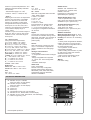
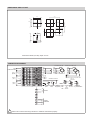
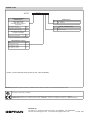
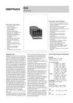
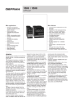
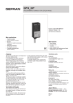
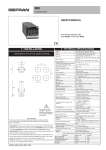
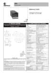
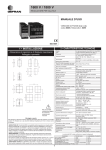
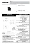
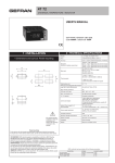
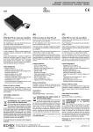
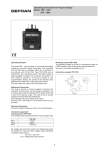
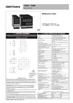
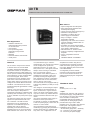
40 TB
TEMPERATURE AND PRESSURE DOUBLE INDICATOR / ALARM UNIT
Main features
Main Applications
• Indication and alarm of
melt temperature and pressure
on extrusion lines.
• Test benches.
• Food processing plants:
temperature and pressure
indication.
• Weighing
• Pressure switches, thermostats
• Textile plants
of 16,000 divisions (by a 120msec.
sampling time). The second input channel
can be configured for inputs from
The 40 TB is a microprocessor based,
temperature sensors (TC, RTD, PTC,
2-channel alarm unit, format 96x96
NTC) and for mV, V, mA signals, with the
(1/4 DIN), manufactured with SMT.
ability to have of having a customized
Its operator interface is comprehensive
input for each kind of sensor.
and efficient, with two 4-digit displays for
the two process variables and engineering The selection of the different options is
available from keyboard. There is the
units indications. It is also equipped with
possibility of having two digital inputs
a red LED bargraph, which can be
from voltage-free contacts, configurable
associated to process variables and to
for functions such as reset, hold, flash,
peak values. Three LEDs indicate the
peak or memory reset control.
output status, while 3 more LEDs can be
The instruments can be equipped with up
configured to indicate different functional
to three relay (5A/250V) or static (0-11Vdc)
conditions. The instrument has a lexan
membrane faceplate (guaranteed to IP65) outputs.
Two voltage or current analogue outputs
with 4 keys.
are available for the retransmission of
Channel 1 has strain gauge, pressure or
inputs, of alarm sets, of gross and tare
force sensor inputs, with positive or
symmetrical polarisations, calibration with values. The serial communication option
sensitivity auto-calculation (from 1,5 up to may have current loop, RS422/ 485 and
4 mV/V), indication of probe power supply RS232 connections with baud rate up to
19200.
break.
The option “transmitter power supply” is
The first input channel can also receive
foreseen for each input channel.
signals from potentiometers with 100Ω
For channel 1 it could be: 1V (potentiometer),
min. resistance. The A/D converter
5 and 10V (strain-gauge), 15 and 24V; for
performance can be configured via
channel 2: 15 and 24Vdc.
keyboard, so that different options of
The programming of the instrument is
sampling time can be selected,
made easy by grouping the parameters in
depending on the desired resolution.
Sampling time can be as low as15msec., function blocks and by a simplified data
entry menu. The configuration can be
while resolution can reach a max. value
PROFILE
• Inputs configurable from faceplate.
• Easy strain-gauge calibration with
sensitivity auto-ranging.
• Control of sensor power supply (input 1).
• Selectable code protection.
• Possibility to configure the unit.
• Power supply for transmitters.
• Easy to configure . Custom
linearization available.
• Engineering units of the most common
physical quantities available either on
display or on labels.
• Acquisition and alarm programmable
from 15 up to 120 msec. with resolution
from 16000 to 4000 divisions
• Retransmission of variable values
• 3 alarms completely configurable from
faceplate.
• 4-wire, configurable serial line.
Protocol:
GEFRAN CENCAL or MODBUS
simplified even further using the PC
programming kit containing connection
cable and a menu guide program that
runs under Windows (see technical data
code WINSTRUM).
A configurable personal software
protection code (password protection)
can be used to restrict the levels of
editing and displaying the configuration
parameters.
TECHNICAL DATA
INPUTS
Accuracy 0.2% f.s. ± 1 digit.
- Input 1
Sampling time 120 msec. with control of
sensor power supply, configurable down
to a minimum of 15 msec. with reduction
of the resolution to 4000 points.
Configurable decimal point position for
linear inputs, for strain gauge inputs or
potentiometer range -1999…9999,
indication of min. and. Max. over-range for
linear inputs. A 32-segment custom
linearisation can be entered.
- 4/6 wire strain gauge 350Ω, sensitivity:
1.5…7.5mV/V by 10V power supply
1.5…15mV/V by 5V power supply.
Positive or symmetrical polarisation and
calibration that automatically calculates
the sensitivity.
- Potentiometer supply 1.2V >100Ω
-Current 0…20mA, 4…20mA, Ri= 50Ω.
- Input 2
Sampling time 120 msec. for temperature
sensors, for linear inputs, configurable
down to a minimum of 15 msec. with
reduction of resolution to 4000 steps.
Configurable decimal point position for
linear inputs, for TC, RTD, PTC, NTC
inputs only one decimal point is allowed
in the maximum display range of
-199.9…999.9.
Indication of open circuit thermocouple or
RTD, PTC, NTC in open or short circuit,
indication of over- and under-range for
linear inputs.
TC – Thermocouple
Cold junction auto-compensation.
J (Fe-CuNi) 0...1000°C / 32...1832°F
K (NiCr-Ni) 0...1300°C / 32...2372°F
R (Pt13Rh-Pt) 0...1750°C / 32...3182°F
S (Pt10Rh-Pt) 0...1750°C / 32...3182°F
T (Cu-CuNi) -200...400°C / -328...752°F
B (Pt30Rh-Pt6Rh) 44...1800°C / 111...3272°F
E (NiCr-CuNi) -100...750°C / -148...1382°F
N (NiCrSi-NiSi) 0...1300°C / 32...2372°F
(Ni-Ni18Mo) 0...1100°C / 32...2012°F
L-GOST (NiCr-CuNi) 0...600°C / 32...1112°F
U ( ) -200...400°C / -328...752°F
G ( ) 0...2300°C / 32...4172°F
D ( ) 0...2300°C / 32...4172°F
C ( ) 0...2300°C / 32...4172°F
Custom -1999...9999
RTD 3 wires
Pt100 -200...600°C / -328...1112°F
JPt100 -200...600°C / -328...1112°F
PTC
990Ω 25°C
-55...120°C / -67...248°F
NTC
1 KΩ 25°C
-10...70°C / 14...158°F
POWER SUPPLY
Standard: 100…240Vac/dc ±10%
On demand: 20…27Vac/dc ±10%
50/60Hz; 12VA max.
Protected by an internal fuse (not
replaceable by the operator).
DC – Linear
With scale configurable within the limits:
-1999...9999 (4 digits)
0...60mV / 12...60mV
0...10V / 2...10V
0...5V / 1...5V
0...1V / 0.2...1V
0...20mA / 4...20mA
Input impedance for voltage signals
Ri>500Ω for V ≤ 1V; Ri >20KΩ for
V > 1V, for current signals: Ri = 50Ω.
A 32-segment configurable linearisation
can be used.
SENSOR POWER SUPPLY (VS)
1.2Vdc for potentiometer > 100Ω
5Vdc, 10Vdc max 120mA for strain-gauge
Available for input 1 (Terminal 11).
TRANSMITTER POWER SUPPLY (VT)
24Vdc ±10% max. 50mA
15Vdc ±10% max. 80mA
Available for input 1 (Terminal 11) and
input 2 (Terminal 3).
Digital
2 inputs from contact free of potential.
The function is selectable among stored
alarm reset, hold, flash, zero, selection of
peak value (minimum, maximum, or
peak-to-peak).
AMBIENT CONDITIONS
Working temperature range: 0...50°C
Storage temperature range: -20...70°C
Humidity: 20...85% HR non condensing
ALARMS
- 3 alarm points configurable as absolute,
relative, with direct or inverse function.
- Alarm points with configurable limits on
the whole selected scale.
- The hysteresis of each alarm is
configurable individually.
- Alarm masking with exclusion on power
up, with memory, delay and minimum
alarm/intervention time.
- Alarms can be associated to single
inputs, either as “OR” or “AND”.
OUTPUT
Relay with NO(NC) contacts 5A, 250V
cosϕ=1. Three alarms configurable as
output to calibrate 6-wire strain-gauge
probes.
Analogue retransmission
1500V Isolation
- 2 configurable retransmission analogue
outputs.
- Range configurable from keyboard.
- 0…10Vdc; 0/4…20mA configurable
outputs.
- Resolution 4000 steps.
WEIGHT
Full version: 600g
SERIAL LINK
4-wire, optoisolated.
Passive current loop configurable
interface (1200 bauds), RS232 and
RS422/485 (1200, 2400, 4800, 9600,
19200 bauds) Protocol: GEFRAN,
CENCAL or MODBUS.
FACEPLATE DESCRIPTION
A - Indication of input 1 variable,
13mm high digits, red LED display.
B - Indication of input 2 variable,
13mm high digits, red LED display.
C - “Function” key
D - “Lower” key
E - “Raise” key
F - Configurable function key (CAL standard)
G - Indication of CAL, ZERO, REM, red LED display
H - Indication of Out1, Out2, Out3 alarms, red LED display.
I - Label for engineering units
H
A
I
B
G
I
F
IP 65 faceplate protection
E
D
C
DIMENSIONS AND CUT-OUT
96
115
108 96
115
92
92
113
10
Dimensions 96x96 (1/4 DIN), depth 113 mm
CONNECTION DIAGRAM
STRAIN-GAUGE INP
PWR
ALIMENTAZIONE
NC
OUT 1
(MAIN)
OUT 2
(AL1)
C
+ECC
+ECC
+IN
+IN
+IN
-IN
-IN
-IN
-ECC
-ECC
-ECC
NO
IN2
NC
IN1
C
STRAIN-GAUGE INP 6 FILI
+ECC
POT INP
CAL
CAL
COM
Out3 (or Out2 or Out1) Relé C/NO
INGRESSO DIGITALE
NO
Coll. per
INP 20mA
NC
OUT3
(AL2)
C
NO
TC Pt100 PTC Pt100 LIN INP
LIN
3FILI
2FILI
Idc (20mA) INP
Vdc
+W2
+W1
OUTW
0V
Tx
LINEA
SERIALE
Rx
!
Follow user’s manual mounting instruction to install the instruments properly.
LIN INP LIN INP
LIN INP
TX
Tx 3 fili 1,2V potentiometro
2 FILI
4-20mA
ORDER CODE
40 TB
R R R
SENSOR/TRANSMITTER
POWER SUPPLY
Sensor Power Supply
(VS) input 1 only
(Transmitter Power Supply VT
not present)
1,2Vdc (potentiometer)
01
POWER SUPPLY
0
20...27Vac/dc
1
100...240Vac/dc
DIGITAL COMMUNICATION
5Vdc/120mA (strain-gauge)
05
0
None
10Vdc/120mA (strain-gauge)
10
2
RS 485 / RS232C
Transmitter Power Supply (VT)
for input 1 and input 2
15Vdc/80mA (transmitter)
(*)
15
24Vdc/50mA (transmitter)
(*)
24
(*) Input 1 is configured for 4…20mA input
RETRANSMITTED OUTPUTS
None
0
1 retransmitted output
0/4...20mA (0...10V)
1
2 retransmitted outputs
0/4...20mA (0...10V)
2
Please, contact GEFRAN sales people for the codes availability.
GEFRAN spa reserves the right to make any modification of the design or function, at any moment without prior notice.
Conformity C/UL/US File no. E216851
The instrument conforms to the European Directives 89/336/CEE and 73/23/CEE with reference to the generic standards:
-CEI-EN 61000-6-2 (immunity in industrial environments) – EN 50081-1 (emission in residential environments) - EN 61010-1(safety)
GEFRAN spa
via Sebina, 74 - 25050 Provaglio d’Iseo (BS) -Tel. 03098881 - fax 0309839063
Internet: http://www.gefran.com - e.commerce:www.gefranonline.com
cod. 40TB - 06/04