1
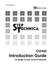
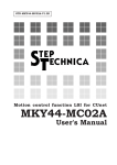
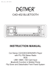
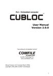
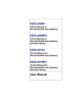
DS-MKY44-DA16A-V1.1E
CUnet Family
MKY44-DA16A
DATA SHEET
http://www.steptechnica.com/
MKY44 Series CUnet-Compliant Intelligent Slave ICs
key words : 2ch 16 bits D/A 2 types of analog output update mode
8 bits DI 8 bits DO
n MKY44-DA16A Specifications
l Model
l ADC
: MKY44-DA16A
: AD5752 external with SPI
connection
: 2-channel
l Number of channels
l Analog output update mode
• CC(CUnet Cycle)
• SNS(Sequential Number Synchronization)
l DIO
l Power voltage
l Power consumption
l Temperature range
l Package
l ST44SW
:
:
:
:
:
8 bits DI/8 bits DO
3.3 V
20 mA
-40 to +85 °C
64-pin TQFP (0.5 mm pitch 10
mm × 10 mm)
: Required
Specifications of Analog Devices D/A Converter AD5752
l Built-in output amplifier
: +5 V, +10 V, ±5 V, ±10 V
l Analog output range
l D/A conversion resolution : 16 bits
l Integral non-linearity error : Max. ±16 LSB
l Differential linearity error : Max. ±1 LSB
: 2-channel
l Number of channels
n Applications
Industrial devices
Medical devices
Measurement devices
Power wire monitoring
Process control
n Overview
The MKY44-DA16A is a CUnet station IC with analog output
function. With an MKY44-DA16A, analog output and DIO
control can be achieved on one chip without using the CPU, by
connecting an AD5752 (Analog Devices DA converter) by SPI.
DA and DO output speed depends on the speed of the CUnet
network. Because a CUnet network allows multiple-master
configurations, to output DA and DO, the IC must specify the
CUnet IC to be its master. The MKY44-DA16A's DOSA (Data
Output Station Address) pin is used to specify the network
address of the IC to be its master. When this is done, the
MKY44-DA16A outputs the control data written to the memory
of the specified master. Input data (DI) is automatically input
to the MKY44-DA16A's own memory block and automatically
copied to all CUnet ICs through CUnet communication (memory
sharing). Existing users of CUnet can get analog output control
just by adding this product to their networks. New users have
the opportunity to reduce DA control wiring that used to use
parallel connections and to achieve easy, networked analog
control.
--- Page 1 / 12 ---
CUnet Family MKY44-DA16A
n D/A Conversion Timing and Output Clear Function
CUnet executes communication regularly. The data to output the analog voltage is regularly passed to the MKY44-DA16A through
this cycle. The MKY44-DA16A using this data has two analog output update modes; CC (CUnet Cycle) and SNS (Sequential
Number Synchronization).
If CC is selected as the analog output update mode, it will update the analog output voltage at the next CUnet time period after the
DOSA value for each CUnet cycle. The cycle time of CUnet is a constant value based on the transfer rate, etc. For example, in a
system with 4 nodes at 12 Mbps, the cycle time would be 155 μs. In this example, if the application has the user CPU constantly
change the CUnet shared memory data that is the analog output of the D/A station by rewriting it, the analog output voltage of the
D/A station will be updated every 155 μs.
If SNS is selected as the analog output update mode, it will update the analog output voltage only when the SN (Sequential
Number) value for update notification changes. Furthermore, this is only if SN does not change to “0x00”. In this mode, you
can maintain the analog output voltage of the MKY44-DA16A by leaving SN as “0x00” in cases such as when the sender of the
analog value is not ready during the initial state after a reset. Also, by making the sender of the analog value update the SN value
in a chosen time, you can control the update time of the analog output voltage for the MKY44-DA16A.
If the analog values of both ch0 and ch1 are updated at the same time, the MKY44-DA16A controls DAC so that the analog
outputs of both ch0 and ch1 change simultaneously. Also, if the communication cable of the D/A station is disconnected,
or if data cannot reach the MKY44-DA16A because the device to write the CUnet shared memory data for analog output is
disconnected from communication, the MKY44-DA16A will be able to clear the analog output voltage (setting it to “0x0000”).
In this case, pin #DoClr can be set to select whether to clear the analog output voltage or to maintain the existing output voltage.
n DOSA Setting and Output Target Data
The MKY44-DA16A treats as the output target the MB (Memory Block) data corresponding to the specified DOSA value.
(1) The word in bits 15 to 0 is the analog output data of ch0. The word in bits 31 to 16 is the analog output data of ch1. Since the
data is in little-endian format, the LSB is in the smallest address. D/A conversion is performed with SNS (Sequential Number
Synchronization) or CC (CUnetCycle) according to the setting of pin #SNS, and the analog output voltage is updated in the
data in this area. The analog output value is echoed back to the EAO (Echo back Analog Out) area of the MB specified by the
SA setting.
(2) The byte in bits 39 to 32 is the data to output to the general-purpose output pin. The MKY44-DA16A outputs the data to the
general-purpose output pin in the next CUnet time period after the DOSA value for each CUnet cycle.
(3) The 2 bytes in bits 55 to 40 are “d.c.” (don’t care). The value in this area will not affect the operation of the MKY44-DA16A.
(4) The MKY44-DA16A refers to the sequential number (SN) of bit 63 to 56. This value returns an echo to the ESN (Echo back
Sequential Number) area of the MB specified by the SA setting.
Address
bit
0x07
0x06
63 to 56
55 to 48
SN
--- Page 2 / 12 ---
0x05
47 to 40
d.c.
0x04
0x03
0x02
0x01
0x00
39 to 32
31 to 16
15 to 0
Do7 to Do0
Analog Out ch1
Analog Out ch0
CUnet Family MKY44-DA16A
n Data Placement of the Occupied Memory Block
The MKY44-DA16A occupies one MB (memory block) corresponding to the specified SA value. The MB occupied by the MKY44DA16A is 8 bytes (64 bits). The data configuration within the 8 bytes is as follows.
Address
bit
0x07
63 to 56
ESN
0x06
55 to 48
Status
55
54
53
52
SPIED DoClr VOLsel SPIE
0x05
47 to 40
EDo
51
SNS
50
DiInv
0x04
39 to 32
Di7 to Di0
49
“0”
0x03
0x02
31 to 16
Echo back Analog Out ch1
0x01
0x00
15 to 0
Echo back Analog Out ch0
48
POLsel
(1) EAO (Echo back Analog Out), in bits 31 to 16 and in bits 15 to 0, is the echo of the analog output data (AO: Analog Out)
shown to the MB that is specified by the DOSA setting. The analog value output to ch1 is shown in the word in bits 31 to 16.
The analog value output to ch0 is shown in the word in bits 15 to 0. Since the data is in little-endian format, the LSB is in
the smallest address. The value will show “0x0000” from right after reset until the first analog value output. Whether these
values are output as Bipolar (0x8000 to 0x0000 to 0x7FFF) or Unipolar (0x0000 to 0xFFFF) depends on the setting of pin
#POLsel. The state of pin #POLsel is shown in the POLsel bit of bit 48.
When they are set as Bipolar, the POLsel bit is “1”.
(2) The state of pin Di is shown in one byte in bits 39 to 32. The data of the general-purpose input pins (Di7 to Di0) depends on
the setting of pin #DiInv. The setting status of pin #DiInv is shown in the DiInv bit, bit 50. If DiInv is “0,” the 1 byte data of
bits 39 to 32 will be shown by positive logic. In such a case, the status of the eight general-purpose input pins will be shown
as “0” when in Low-level and as “1” when in High-level. If the DiInv bit is “1,” the data will be shown by negative logic.
Thus, the status of the general-purpose input pin will be shown as “1” when at Low-level and as “0” when at High-level.
(3) EDo (Echo back Data out), the byte from bit 47 to bit 40, is the echo back of the general-purpose output pin data (Do) shown
in the MB specified by DOSA setting. By referring to this byte, the device sending out the Do data can confirm that the data
is successfully output to the general-purpose output pin.
(4) The byte from bit 55 to bit 48 shows the setting condition and status of MKY44-DA16A. (The unused bit is “0”.)
Bits 54, 53, 51, 50, 48: Shows by negative logic the individual settings read out from pins #DoClr, #VOLsel, #SNS, #DiInv,
and #POLsel when returning from a reset.
Bit 52:
SPIE (SPI Error) sets “0” if the connection with D/A conversion element is normal when sampling
the analog value, or “1” if the connection is abnormal.
Bit 55:
Shows “1” when the output of pin #SPIED is Low.
(5) The byte in bits 63 to 56 (ESN: Echo back Sequential Number) is the echo of the sequential number (SN) shown to the MB that is
specified by DOSA setting. The device sending out the SN can ensure that the SN data sent is properly transferred to the other party
by referring to this byte.
--- Page 3 / 12 ---
CUnet Family MKY44-DA16A
n DIP-SW Settings for SA/DOSA
MKY44-DA16A reads out the 16 bits of hardware setting data as serial data from the ST44SW, a dedicated LSI, when returning from
hardware reset. It is recommended to connect two 8-bit type DIP-SWs to an ST44SW specified for hexadecimal.
The pins to connect a DIP-SW to the ST44SW are pulled up internally when reading from the DIP-SW. These bits recognize the ON
state (Low-level) as “1”. The following shows MKY44-DA16A’s definitions for the bits of the DIP-SWs for setting.
Pin
Name
DIP-SW No.
Signal
1
#P17
8
RESERVED
32
#P16
7
RESERVED
31
#P15
30
#P14
29
#P13
28
#P12
3
27
#P11
2
DOSA1
26
#P10
1
DOSA0
21
#P07
8
BPS1
20
#P06
7
BPS0
19
#P05
6
SA5
18
#P04
5
SA4
17
#P03
16
#P02
3
15
#P01
2
SA1
14
#P00
1
SA0
Function/Description
Reserved bit. Turn it off when in use.
DIP•SW•DOSA
6
DOSA5
5
DOSA4
4
DOSA
DOSA3
DOSA2
BPS
DIP•SW•SA
4
SA
SA3
SA2
Set DOSA value in hexadecimal, treating the ON state as “1”
Set the transfer rate of CUnet.
BPS1, BPS0 = OFF, OFF 12 Mbps
BPS1, BPS0 = OFF, ON
6 Mbps
BPS1, BPS0 = ON, OFF
3 Mbps
BPS1, BPS0 = ON, ON (This setting is disabled.)
Set SA value in hexadecimal, treating the ON state as “1”
The ST44SW has a function that can set SA and DOSA in decimal. For details on setting in decimal, refer to the User’s Manual of
ST44SW.
n Setting of Pins #POLsel, #VOLsel, #SNS, #DoClr, and #DiInv
The MKY44-DA16A has pins #POLsel, #VOLsel, #SNS, #DoClr, and #DiInv to set the functions. The MKY44-DA16A obtains the
status of these setting pins when returning from a hardware reset. Activate the MKY44-DA16A after setting these pins to fit the user
application.
MKY44-DA16A
Pin
Name
18
#POLsel
19
Description
Function
Lo-input
Hi-input (open pin)
Analog output type
selection
Bipolar: ±n V input
Unipolar: 0 V to +n V input
#VOLsel
Analog output voltage
selection
10 V
5V
20
#SNS
SN synchronization
analog output update
Update the analog output by updating SN
(SNS: Sequential Number Synchronization)
Update the analog output for each CUnet cycle
(CC: CUnet Cycle)
21
#DoClr
Clear output when in
DONA
Clear output when in DONA
Do not clear output when in DONA
22
#DiInv
Di logical inversion
selection
Logical inversion
No logical inversion
When the MKY44-DA16A returns from hardware reset, the setting conditions read out from pins #POLsel, #VOLsel, #SNS, #DoClr,
and #DiInv are shown in Status byte of the occupied memory block by “1” for Low-level and “0” for High-level.
--- Page 4 / 12 ---
CUnet Family MKY44-DA16A
n Monitor pins of CUnet
Pin
Function
#PING
This pin normally maintains High-level. It transitions to Low-level when the PING instruction is received from another CUnet
station, and later it transitions to High-level when a packet with no PING instruction to MKY44-DA16A is not placed is received
from another CUnet station.
#CYCT
This pin normally maintains High-level and outputs Low pulse for “2 × Tbps” time at the lead timing of the CUnet cycle.
Tbps is 83.33 ns at 12 Mbps, 166.67 ns at 6 Mbps, and 333.33 ns at 3 Mbps.
#MON
This pin outputs the MON signal, which is a standard function of CUnet. This pin retains Low-level while a link has been
established with another CUnet device for at least 3 consecutive cycles.
#LCARE
This pin outputs the LCARE signal, which is a standard function of CUnet. This pin outputs the Low-level for 50 ms when the
LCARE signal is generated and upon return from hardware reset. As a unique function of the MKY44-DA16A, the Low-level
output of this pin is also used to display hardware errors including setting errors.
#MCARE
This pin outputs the MCARE signal, which is a standard function of CUnet. This pin outputs the Low-level for 50 ms when the
MCARE signal is generated and upon return from hardware reset. As a unique function of the MKY44-DA16A, the Low-level
output of this pin is also used to display hardware errors including setting errors.
DONA
This pin outputs the Low-level when it can confirm the presence of another party issuing operation commands to the MKY44DA16A.
When it has not confirmed the presence of another party in the past 16 consecutive cycles, it outputs the High-level.
n Connection of LEDs and Display Status
LED connection is recommended for the #MON, #LCARE, #MCARE, DONA pins of MKY44-DA16A. It is recommended to
connect green color LED part indicating a stable operation to #MON pin and DONA pin. To #LCARE pin, it is recommended to
connect orange color LED part indicating a gentle warning. To #MCARE pin, it is recommended to connect red color LED part
indicating a definite warning. These pins have ±2mA current drive capability. Connect them in such a way that the LEDs will light
up at Low-level.
The LEDs display the status of MKY44-DA16A. The state in which MON and DONA are lit is when normal operation is possible.
Note: The following table does not cover the pin name “#” that shows negative logic, since it is based on signal names.
DONA
MON
LCARE
MCARE
---
---
---
---
---
---
---
---
---
---
---
---
---
---
---
---
---
---
---
---
State
Indicates the state of power off, the state when the #Reset pin is active, or the state when no
CUnet devices is linked after returning from hardware reset.
Although a link is successfully established with at least one CUnet device, the station address
device (the other party that writes the data to the MKY44-DA16A) set by DOSA is missing.
The connection of the CUnet network is normal.
The setting values of SA and DOSA of DIP-SW are inappropriate.
-----
: Continuous lighting
When it becomes clear that at least one CUnet link is not established, the LED flashes for
approximately 50 ms.
When it becomes clear that at least one CUnet link has not been established during the last 3
consecutive scans, the LED flashes for approximately 50 ms.
When it becomes clear that at least one CUnet link has been disconnected during the last 3
consecutive scans, and when hardware reset is executed, the LED flashes for approximately 50
ms.
The following internal hardware of MKY44-DA16A is abnormal.
Blink alternately every second
⇒ DIP-SW read hardware including ST44SW
Blink alternately every two seconds ⇒ MKY44-DA16A internal hardware
Please perform maintenance such as replacement.
: Flash lighting for about 50 ms
: Alternating lit and unlit every few seconds
Unique to MKY44-DA16A display, the status in which only MCARE stays lit means that the settings of SA and DOSA of DIP-SW
are inappropriately identical or overlapping values. If LCARE and MCARE keep blinking every few seconds, it means a failure
caused by a crash in MKY44-DA16A.
The other signal transitions of MON, LCARE, and MCARE are standard CUnet operation. For more information about these signals,
refer to the section “Quality Control and Indication of Network” and others in the User’s Manual of the CUnet-dedicated LSI that is
installed in the device to refer to the MKY44-DA16A data.
--- Page 5 / 12 ---
CUnet Family MKY44-DA16A
n Support for CUnet mail
The MKY44-DA16A supports the “product inquiry” function of CUnet mail.
l Product Inquiry Using the Mail Function
Upon receiving a message in product inquiry format using the “CUnet ?” character string, the MKY44-DA16A replies to the sender
using the basic format of the MKY44-DA16A (see below). You can make a product inquiry from any node.
u Product Inquiry Format
Address
0x00
0x01
0x02
0x03
0x04
0x05
0x06
0x07
Ascii
C
U
n
e
t
[sp]
?
[¥r]
Hex
0x43
0x55
0x6E
0x65
0x74
0x20
0x3F
0x0D
0x03
0x04
0x05
0x06
0x07
u Basic Format of the MKY44-DA16A
Address
0x00
0x01
0x02
Ascii
D
A
1
6
A
[sp]
*VN
*Vn
Hex
0x44
0x41
0x31
0x36
0x41
0x20
k
k
Address
0x08
0x09
0x0A
0x0B
0x0C
0x0D
0x0E
0x0F
M
k
k
k
k
k
k
k
0x4D
0x00
SA
DOSA
Status
0x00
0x00
0x00
Ascii
Hex
⇒
⇒
u Description of the Basic Format
Symbol
Name
Description
Valid range
Version Number
Shows the version number of the MKY44-DA16A in two ASCII characters. The
version numbers start from “01.” *VN represents the tens place and *Vn represents
the ones place.
01 to 99
(in ASCII)
SA
DIP-SW-SA
Shows the DIP-SW-SA data shown in the section “DIP-SW Settings for SA/DOSA”
as one hexadecimal byte.
0x00 to 0xFF
DOSA
DIP-SW-DOSA
Shows the DIP-SW-DOSA data shown in the section “DIP-SW Settings for SA/
DOSA” as one hexadecimal byte.
0x00 to 0xFF
Status
Status
The same content as the "Status" in bits 55 to 48, shown in "Data Placement in the
Occupied Memory Block" (page 3 of this document), is shown as one hexadecimal byte.
0x00 to 0xFF
*VN
*Vn
If the MKY44-DA16A receives a message in a format different from a “CUnet ?” character string, it will return a message in NAK
format, in which byte 0x08 of the basic format is “N”. In this case, the NAK reason of “0xE0” or “0xE1” will be shown in byte
0x09.
--- Page 6 / 12 ---
Byte 0x09
Definition
0x03
The received byte 0x09 (MC: Message Code) is not “0x00.”
0xE0
The first 8 bytes are irregular.
0xE1
The format is irregular.
0xE2
The mail data size is irregular.
CUnet Family MKY44-DA16A
n Configuration Example of the CUnet Analog Input Terminal with the MKY44-DA16A
As shown in the configuration diagram of the CUnet analog input terminal with the MKY44-DA16A, the signal of the MKY44The network interface (pins CU_TXE, CU_TXD, CU_RXD) signal of the MKY44-DA16A is connected to CUnet through the
recommended transceiver and pulse transformer. It connects the MKY44-DA16A and the Analog Devices AD5752.
If a current conversion or voltage amplification circuit is required before the analog output of the AD5752, please prepare a circuit
that fits the application.
If the voltage output from the AD5752 is ± nV (Bipolar), set the Low-level to pin #POLsel of the MKY44-DA16A.
With this setting, write D/A conversion data representing -32768 to 0 to 32767 (0x8000 to 0x0000 to 0x7FFF) in the shared memory
of CUnet when the sender of the analog value sets the value. If the voltage output from the AD5752 is 0V to + nV (Unipolar), set
the High-level to pin #POLsel of the MKY44-DA16A. In this setting, write D/A conversion data representing 0 to 65535 (0x0000 to
0xFFFF) in the shared memory of CUnet when the sender of the analog value sets the value.
The MKY44-DA16A requires the ST44SW, a dedicated LSI to load DIP-SW settings. In a hardware reset, the MKY44-DA16A
reads its station address, the transfer rate, the general-purpose output, and the output data controller’s station address via the ST44SW
to start operation. The MKY44-DA16A has an SPI connection monitor. When SPI connection is normal, the High-level is output
to pin #SPIE (SPI Error). When it is abnormal, the Low-level is output to pin #SPIE. The output to this #SPIE pin is updated when
the analog value is sampled. The MKY44-DA16A normally outputs the High-level to pin #SPIED (SPI Error Detect). However,
after detecting an SPI connection error, it will continue outputting the Low-level to pin #SPIED until the next hardware reset. For
applications in which SPI connection errors are detected, it is recommended to perform maintenance to enhance the quality and
stability of the device peripheral environment and hardware.
--- Page 7 / 12 ---
CUnet Family MKY44-DA16A
n Pin Functions of the MKY44-DA16A
Pin name
Pin number
Logic
I/O
Function
DEC1UF
3
--
--
Connect a capacitor whose effective capacitance is at least 1 μF and a 0.1 μF ceramic capacitor
for high frequency bypass in parallel between this pin and Vss. Or connect a laminated ceramic
capacitor of around 2.2 μF with the property that capacitance reduction is about 20% even in DC
bias.
#Reset
6
Negative
I
The hardware reset input pin of MKY44-DA16A. Right after power is turned on or when the
user intentionally resets the hardware, Low should be retained for at least 200 μs.
XTAL4i
XTAL4o
10, 11
--
--
Pins to connect a crystal oscillator. Connect a 4 MHz crystal oscillator between these pins.
Connect 20 pF ceramic capacitors between these pins and Vss. Connect them near the pins.
DIP_ON
15
Positive
O
Connect this pin with pin DIP_ON of the ST44SW. For more information about the ST44SW,
refer to the ST44SW User’s Manual.
DIP_RX
17
Positive
I
Connect this pin with pin DIP_TX of the ST44SW. For more information about the ST44SW,
refer to the ST44SW User’s Manual.
#POLsel
18
Negative
I
Pin to set whether the analog output type should be treated as Bipolar (±n V) or Unipolar (0 V
to +n V).
#VOLsel
19
Negative
I
Pin to select the voltage of analog output.
#SNS
20
Negative
I
Pin to set the update mode of analog output to SNS (Sequential Number Synchronization).
#DoClr
21
Negative
I
Setting pin to clear output when in DONA.
#DiInv
22
Negative
I
Pin to set logical inversion of Di0 to Di7.
#DA_CLR
26
Negative
O
Function pin to force D/A output to be “0x0000”. Connect it to pin #CLR of the AD5752.
Di0 to Di7
27 to 34
Positive
I
8 bits of general-purpose input pins. Leave these pins open when not in use (internal pull-up).
Do0 to Do7
35 to 42
Positive
O
8 bits of general-purpose output pins. Leave these pins open when not in use.
SPI_MISO
43
Positive
I
MISO function pin of SSPI. Connect it to pin SDO of the AD5752.
SPI_MOSI
44
Positive
O
MOSI function pin of SSPI. Connect it to pin SDIN of the AD5752.
SPI_SCK
45
Positive
O
SCK function pin of SPI. Connect it to pin SCLK of the AD5752.
#SPI_SS
46
Negative
O
#SS function pin of SPI. Connect it to pin #SYNC of the AD5752.
DONA
47
Positive
O
This pin retains the High-level during the DONA (DO Not Arrival) state.
It is at Low-level at other times.
#DA_LOAD
48
Negative
O
Control pin to batch update D/A output. Connect it to pin #LOAD of the AD5752.
#PING
50
Negative
O
A pin to output the PING signal, which is a standard function of CUnet. When the PING signal
occurs, this pin transitions to Low-level.
#CYCT
51
Negative
O
A pin to output the CYCT signal, which is a standard function of CUnet. When the CYCT signal
occurs, this pin transitions to Low-level.
#MCARE
53
Negative
O
A pin to output the MCARE signal, which is a standard function of CUnet. This pin outputs the
Low-level for about 50 ms, when the MCARE signal occurs and when it returns from hardware
reset.
It is recommended to connect red color LED indicating a definite warning to this pin.
#LCARE
54
Negative
O
A pin to output the LCARE signal, which is a standard function of CUnet. This pin outputs the
Low-level for about 50 ms, when the LCARE signal occurs and when it returns from hardware reset.
It is recommended to connect orange color LED indicating a gentle warning to this pin.
#MON
55
Negative
O
A pin to output the MON signal, which is a standard function of CUnet. This pin retains Low-level
while a link has been established with another CUnet devices for at least 3 consecutive cycles.
It is recommended to connect green color LED indicating a stable operation to this pin.
CU_TXD
56
Positive
O
Output pin to send CUnet packets. Connect this pin to a drive input pin such as of a driver.
CU_TXE
57
Positive
O
A pin to output the High-level while CUnet packets are output.
Connect this pin to the enable input pin of the driver.
CU_RXD
58
Positive
I
A pin to input CUnet packets. Connect this pin to the output pin of the receiver.
#SPIE
60
Negative
O
Pin monitoring the SPI connection state. This pin outputs the Low-level when an SPI error is
active. The output of this pin is updated when the analog value is sampled.
#SPIED
61
Negative
O
This pin normally outputs the High-level, but outputs the Low-level from when an SPI
connection error is detected until hardware reset.
Vdd
1, 2, 4, 23
Vss
5, 9, 12
N.C.
7, 8, 13, 14, 16
24, 25, 49, 52
59, 62, 63, 64
--- Page 8 / 12 ---
Power pin. Supply 3.3 V.
Power pin. Connected to 0 V.
Do not connect to other signals; keep them open.
CUnet Family MKY44-DA16A
n Pin Assignment
n Electrical Ratings
(Ta = 25°C Vss = 0 V)
Parameter
Symbol
Conditions
Min.
Typ.
Max.
Unit
Storage temperature
Tstg
---
-55
---
125
°C
Operating temperature
Topr
---
-40
---
85
°C
Pin voltage (absolute maximum rating)
Vi
---
-0.3
---
Vdd+0.3
V
Operating power supply voltage
Vdd
---
3.0
3.3
3.6
V
Mean operating current
VddA
Vi = Vdd or Vss, output open
XTAL = 4 MHz
---
10
20
mA
I/O pin capacitance
Ci/o
Vdd = Vi = 0 V
Ta = 25°C
---
10
---
pF
Rise/fall time of input signal
Ticlk
When inputting generated clock
of XTAL4i pin
---
---
5
ns
Rise/fall time of input signal
Tirf
Schmitt trigger input
---
---
100
ms
--- Page 9 / 12 ---
CUnet Family MKY44-DA16A
n Pin Ratings
No I/O
Name
Type
No I/O
Name
Type
No I/O
Name
Type
No I/O
Name
Type
1
--
Vdd
--
17
I
DIP_RX
A
33
I
Di6
A
49
--
N.C.
--
2
--
Vdd
--
18
I
#POLsel
A
34
I
Di7
A
50
O
#PING
B
3
--
DEC1uF
--
19
I
#VOLsel
A
35
O
Do0
B
51
O
#CYCT
B
--
4
--
Vdd
--
20
I
#SNS
A
36
O
Do1
B
52
--
N.C.
5
--
Vss
--
21
I
#DoClr
A
37
O
Do2
B
53
O
#MCARE
B
6
I/O
#Reset
C
22
I
#DiInv
A
38
O
Do3
B
54
O
#LCARE
B
7
--
N.C.
--
23
--
Vdd
--
39
O
Do4
B
55
O
#MON
B
8
--
N.C.
--
24
--
N.C.
--
40
O
Do5
B
56
O
CU_TXD
B
9
--
Vss
--
25
--
N.C.
--
41
O
Do6
B
57
O
CU_TXE
B
10
--
XTAL4i
--
26
O
#DA_CLR
B
42
O
Do7
B
58
I
CU_RXD
A
11
--
XTAL4o
--
27
I
Di0
A
43
I
SPI_MISO
A
59
--
N.C.
--
12
--
Vss
--
28
I
Di1
A
44
O
SPI_MOSI
B
60
O
#SPIE
B
13
--
N.C.
--
29
I
Di2
A
45
O
SPI_SCK
B
61
O
#SPIED
B
14
--
N.C.
--
30
I
Di3
A
46
O
#SPI_SS
B
62
--
N.C.
--
15
O
DIP_ON
B
31
I
Di4
A
47
O
DONA
B
63
--
N.C.
--
16
--
N.C.
--
32
I
Di5
A
48
O
#DA_LOAD
B
64
--
N.C.
--
--- Page 10 / 12 ---
CUnet Family MKY44-DA16A
n Package Dimensions
--- Page 11 / 12 ---
CUnet Family MKY44-DA16A
Document No.: DS-MKY44-DA16A-V1.1E
Issued: November, 2013
Related Manuals:
StepTechnica Co., Ltd.
CUnet Introduction Guide STD-CUSTU-Vx.xE
CUnet Technical Guide
STD-CUTGN-Vx.xE
CUnet IC
MKY43 User's Manual STD-CU43-Vx.xE
CUnet I/O- IC MKY46 User's Manual STD-CU46-Vx.xE
CUnet HUB- IC MKY02 User's Manual STD-CUH02-Vx.xE
757-3, Shimo-fujisawa, Iruma-shi, Saitama 358-0011 TEL: 04-2964-8804
http:// www.steptechnica.com
Note
1. The information in this data sheet is subject to change without prior notice. Before using this product, please confirm that this is the latest version
of this document.
2.Technical information in this data sheet, such as explanations and circuit examples, are references for this product. When actually using this
product, always fully evaluate the entire system according to the design purpose based on considerations of peripheral circuits and the PC board
environment. We assume no responsibility for any incompatibility between this product and your system.
3. We assume no responsibility whatsoever for any losses or damages arising from the use of the information, products, and circuits in this data
sheet, or for infringement of patents and any other rights of a third party.
4.When using this product and the information and circuits in this data sheet, we do not guarantee the right to use any property rights, intellectual
property rights, and any other rights of a third party.
5. This product is not designed for use in critical applications, such as life support systems. Contact us when considering such applications.
6. No part of this data sheet may be copied or reproduced in any form or by any means without prior written permission from StepTechnica Co., Ltd..
(C) 2013 STEP TECHNICA CO., LTD.
--- Page 12 / 12 ---