1
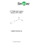
1/3” COLOR CCD CAMERA
Smartec STC-3002
USER’S MANUAL
FEATURES
1. Lead (Pb) Free RoHS Compliance
2. Performance: 540 TV lines of resolution.
3. Digital Signal Processor: SONY HQ1
4. Long life and high reliability are achieved by the use of a CCD
image device. This makes the camera 100 percent solid state. No
longer is an image tube needed.
5. The Minimum illumination 0.08Lux @ F=1.0
6. Ease of use in any application is achieved through the small size.
The lightweight also improves performance where shock and
vibration would affect larger tube type cameras.
7. Lower power consumption.
8. Built-in automatic electronic Iris. This camera can be used for
most indoor application without using the auto iris lens
CAUTION
1. Never point the camera toward the sun
Do not expose the lens directly to the sun or to strong light as this
may damage the pick-up device.
2. Handle this camera with care
Avoid any shock or bumping of the camera. Improper handling
could damage the camera.
3. Requires a proper operating environment
This camera is designed for indoor use. The allowable temperature
range for operation of this camera is between -10°C~50°C and the
allowable humidity is 85% maximum. If the camera is to be placed
outdoors, a special weatherproof housing, which also has heaters
and cooling device included, should be used.
4. Clean the front face to the pick-up device
It is recommended that the pick-up device surface be cleaned
before lens installation or whenever the lens is changed. Cleaning
should be done using a chamois, a very fine soft cloth, lens tissue
or cotton tipped applicator and ethanol to carefully remove any
fingerprints or dust.
5. Check the power source voltage
The power source voltage should be within the specified range. (Camera
must meet the specification)
6. Object and Liquid Entry
Never push objects of any kind into this as this may touch
dangerous voltage points or short-out parts that could result in a
fire or electric shock. Never spill liquid of any kind on the video
product.
7. Servicing
Do not attempt to service this video product yourself as opening or
removing covers may expose you to dangerous voltage or other hazards.
Refer all service to qualified servicing personnel.
8. Damage Requiring Service
Unplug this video product from the wall outlet and refer servicing to
qualified service personnel under the following conditions:
a. When the power-supply cord or plug is damaged.
b. If liquid has been spilled, or objects have fallen into the video product
c. If the video product has been exposed to rain or water.
d. If the video product has been dropped or the cabinet has been
damaged.
e. When the video product exhibits a distinct change in performancethis indicates a need for service.
DIMENSIONS (Unit : mm)
SPECIFICATION
PAL
NTSC
TV System
SONY HQ1
Digital Signal
Processor
1/3” SONY High Super HAD CCD
Image Sensor
811(H)×508(V)
Number of Total Pixels 795(H)×596(V)
Internal / Line Lock (AC Version Only)
Synchronizing System
540TVL
Resolution
0.08Lux @ F1.0
Color mode automatically switches to
Minimum Illumination
B/W mode under 2 Lux
(D/N & S. AGC should be ON)
50dB (AGC OFF)
Signal to Noise Ratio
0.45
Gamma Correction
D4 IRIS Jack
Auto Iris Output
YES
Auto White Balance
ON / OFF (Switchable)
Back Light
Compensation
D/N / Color (Switchable)
Day/Night
AGC / S.AGC (Switchable)
Automatic Gain
Control
Internal / Line Lock (AC Version Only)
Synchronizing System
1.0Vp-p Composite ; 75Ω
Video Output
Iris Control
Video / DC
Electronic Shutter
Speed Control
Lens Mount
Adjustment VR
Power Supply
Power Consumption
Lead Free
Operation
Temperature
Operation Humidity
Storage Temperature
AES ON: 1/50 (60) sec.~1/100,000 sec.
AES OFF: 1/50 (60) sec.
CS mount
L.L V-phase; DC Level
12Vdc /24Vac ; 90~260Vac
12Vdc /24Vac: 3.5W ; 90~260Vac: 4.5W
YES
-10~50
Storage Humidity
Maximum: RH85
-20 ~60
Maximum: RH90
NOMENCLATURE AND FUNCTION
j Lens mount
This
mount
is
used
to
install
a
CS-mount
CS-adaptor ring is required if using a C mount lens.
lens.
k Camera mounting screw holes
Screw hole for fixing camera.
l Mount
adaptor
This adaptor can be attached to either the top or bottom of the unit.
m Mechanical focus adjustment
If focus needs to be adjusted after the lens had been mounted, Losses the
Flange back lock screw (A) and rotate the Adjustment wheel to adjust.
n Auto
iris
lens
connector
(4-pin
type)
The lens connector supplies the auto-iris lens (not supplied) with DC
power and a video signal or DC control signal.
PIN NO. VIDEO
1
2
3
4
DC
CONTROL
DC + 12V CONTROL
NC
+
VIDEO
SIG
DRIVE +
GND
DRIVE -
o Control
SW1. BLC: Backlight compensation OFF / BLC
SW2. Day/Night MODE: D/N / Color switch
SW3. S.AGC/AGC: Super or Automatic Gain Control switch
SW4. SYNC MODE: SYNC Mode Selection L.L / INT switch.
Switch
switch
p VIDEO
connector
This is an output for connection to a video monitor, etc (75Ω).
q Auto Iris mode selection switch
Used to choose DC or VIDEO mode according to the type of
auto iris lens.
your
r V.P (Vertical Phase adjuster)
This is used to adjust the vertical phase of the video output signal and
power supply line.
s Power input terminal
Connect the power supply of 12Vdc or 24Vac.
CONTROL SWITCH OPERATION
the power supply of 90~260Vac.
SW1. BLC (Back light compensation) mode switch:
When the object is dark by strong light (sun illumination etc.), turn on
BLC switch to make object becomes bright.
SW2. D/N mode switch:
COLOR / D/N switch.
D/N: Color mode automatically switches to B/W mode under 2 Lux.
COLOR: Normal position (D/N OFF).
SW3. S.AGC/AGC:
S.AGC: When camera has been installed in the environment with low
illumination, the sensitivity of the camera rises (26dB).
AGC: 26dB. (Color mode only.)
In order to activate D/N function (Color mode automatically switches
to B/W mode under 2 Lux), please switch to S.AGC.
SW4. SYNC MODE:
L.L. MODE: It synchronizes the video signal between cameras by using
the frequency of the power supply without external synchronous
generator.
INT MODE: The camera maybe operated independently with the
internal crystal control.